Abstract
The cycle life and capacity fading mechanisms of secondary sulfur electrodes prepared by two different electrode fabrication methods were studied in an effort to improve the energy density of the cathode. Cycle life improved substantially when the uniformity of carbon distribution around the sulfur particles improved and electrode density increased, improving the overall structural integrity of the carbon matrix. Capacity fading in a high-energy-density cathode is mainly due to structural failure by physical crack propagations of the electrode structure and subsequent formation of the electrochemically irreversible  layer at cracked surfaces of carbon particles or masses. The capacity fading due to these mechanisms appears to be reduced substantially and significantly by improved structural integrity with uniform pore structure of the carbon matrix. A Li/S cell containing a cathode fabricated by the improved technique cycled over 400 cycles without any severe structural damage of the electrode structure. © 2004 The Electrochemical Society. All rights reserved.
Export citation and abstract BibTeX RIS
Demands for high energy density of rechargeable batteries are ever increasing as the power requirements for newer portable electronic devices increase. Rechargeable Li/S cells have been studied extensively in recent years to take advantage of its high theoretical specific energy of 2600 Wh/kg.1 2 3 Although the sulfur cathode is attractive because of its extremely high theoretical specific capacity of 1675 mAh/g, one of the main challenges is overcoming its limited cycle life, especially when sulfur loading is increased to a practically attractive value (e.g., 70% of electrode weight).4 5 6
The electrode reactions of the sulfur cathode include multistep redox reactions involving many polysulfur species such as 


 etc.1
3
5
6 The pure sulfur,
etc.1
3
5
6 The pure sulfur,  which is the starting form of the active material and is substantially insoluble in the electrolyte, dissolves in the electrolyte in the form of
 once discharged partially. The electrolyte-insoluble fully discharged
  species is reported to form at the electrode surface during discharge of the electrode even before the cell is discharged to the sulfur utilization of 50%.1
7
8 The insoluble
species is reported to form at the electrode surface during discharge of the electrode even before the cell is discharged to the sulfur utilization of 50%.1
7
8 The insoluble  is believed to deposit and accumulate at the electrode surface, causing capacity fading as the discharge cycles are repeated even with cycling at less than 50% utilization level.8
9 Such capacity fading is expected to become worse as the sulfur loading increases to improve the energy density of the electrode. The fully charged species,
is believed to deposit and accumulate at the electrode surface, causing capacity fading as the discharge cycles are repeated even with cycling at less than 50% utilization level.8
9 Such capacity fading is expected to become worse as the sulfur loading increases to improve the energy density of the electrode. The fully charged species,  forms only in a limited proportion of the total amount of sulfur in the cell when the cell is fully recharged.4
5
7
forms only in a limited proportion of the total amount of sulfur in the cell when the cell is fully recharged.4
5
7
Despite extensive studies to overcome such cycle life problems, only limited success of achieving reasonably good cycle life of 50 cycles has been reported with relatively low sulfur loading up to approximately 60%.8 10 11 However, it is important to increase the sulfur content to approximately 80% or higher in order to compete with already commercially available secondary batteries such as Li ion.
In the present paper we studied cycle life and capacity fading mechanisms of the cathodes with a high sulfur content of 84%. We report that the formation of insoluble  deposits causes capacity fading with cycling and that an improved electrode structure reduces the capacity fading substantially.
Experimental
All test samples of the sulfur cathode were made of sulfur powder (average particle size 5 μm; Aldrich), Ketchjen black (Japan Carbon), and a styrene-butadiene rubber based binder (Zeon). The ratio of S:carbon:binder was 84:12:4 by weight. This ratio is an empirically optimized value from our earlier work. Type A cathode was prepared by coating the cathode slurry on a carbon-coated aluminum foil using a roll coater. The cathode slurry was prepared by thoroughly mixing the components with deionized water in a planetary wet mixer (Asada) for 12 h at 70 rpm. Thickness of the coating layer was approximately 50 μm. The loading level of sulfur corresponded to 4 mAh/cm2 (1673 mAh/g S). Type B cathode was prepared by a similar method except that the dry components of the sulfur, carbon, and binder were premixed thoroughly in a homemade dry ballmixing apparatus before making the slurry for 12 h. The dry ball mixer was made of 1 cm diam ceramic balls in a rotating polyethylene bottle. The loading level of type B cathode was the same as that of type A, but the thickness of the coating layer was approximately 30 μm.
Li/S test cells were pouch-type wound cells in which the sulfur cathode, a sheet of microporous polypropylene separator (Tonen), and a Li-foil anode (Chemetall Foote) were wound to prepare the cell stack assembly. The Li-metal anode in all test cells had an excess capacity approximately nine times that of the cathode in order to make sure that the cell capacity is not limited by the anode. The assembly was hermetically sealed in an aluminized plastic pouch after addition of the electrolyte. The electrolyte was a 1 M  solution in a mixed solvent of dioxolane, dimethoxyethane, diglyme, and sulfolane (5:2:2:1 by volume). An excess amount of the electrolyte was used in the cell to preclude a possible situation of cell failure due to a cell dry out during the test. The amount of the electrolyte was enough to make the S concentration 4 M if all the sulfur in the cell were dissolved.
The cell cycling performance tests were carried out using a Toyo cycler (Toyo) in the cycle regime of 0.1 C rate charge and discharge rates (0.4 mA/cm2) at room temperature to cutoff voltage of 2.7 and 1.5 V, respectively. Cycle-tested cathodes were removed from the cell in fully discharged or charged states, thoroughly washed with tetrahydrofurane (THF) to remove remaining soluble polysulfides in the electrode, and dried for the following physical examinations: The morphology of sulfur cathode before and after cycling tests were investigated by scanning electron microscopy (SEM) coupled with energy-dispersive X-ray spectroscopy (EDX) using a Philips model XL 30 apparatus. Cross sections of the sulfur cathode were studied in further detail by a focused ion beam (FIB) imaging apparatus (DB235 FEI Corp.). X-ray diffraction (XRD) measurements were carried out using a Philips X-pert MPD 1 diffractometer.
Results and Discussion
Type A cathode.—
Specific discharge capacity values of the cathode are plotted against the number of cycles in Fig. 1. The initial capacity (1st discharge) was 710 mAh/g cathode (theoretical capacity 1404 mAh/g cathode), which corresponds to a little over 50% electrochemical utilization of S. After the 1st recharge (2nd cycle), the specific capacity decreased abruptly. It recovered slightly in several subsequent cycles but started to fade rather rapidly as the cycling continued past roughly ten cycles, as shown in Fig. 1. For example, it decreased to 230 mAh/g at the 50th cycle, showing only 16% utilization of the total sulfur in the cathode. Although the initial specific capacity of 710 mAh/g of the present type A cathode is respectable in comparison with previously reported ones,4 8 9 10 12 13 this cathode is far from attractive for practical battery cells due to its rapid capacity fading with cycling, but it appears to be suitable for an investigation of the capacity fading mechanism.
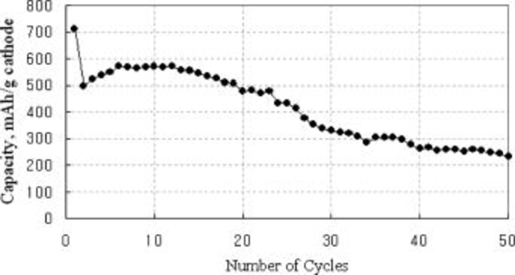
Figure 1. A plot of type A cathode capacity vs. number of cycles in the cycle regime of discharge to 1.5 V at 0.1 C rate (0.4 mA/cm2) and charge to 2.7 V at the same rate.
The charge-discharge voltage curves vs. sulfur utilization values after various numbers of cycles of the type A cathode are shown in Fig. 2. The curves show two discrete voltage plateaus, one at about 2.3 and the other at about 2.0 V, as reported previously.1
7 The upper plateau is known as the reduction of elemental sulfur or highly oxidized polysulfides such as  and
and  to
to  6
7
14
15 while the lower plateau represents the reduction of
6
7
14
15 while the lower plateau represents the reduction of  or lower sulfides to
  or
or  2
7
16
17
18 The upper plateau utilization (238 mAh/g cathode) decreased abruptly to around 5% after the 2nd cycle and stayed unchanged in subsequent cycles, while the lower plateau utilization decreased continuously with cycling. Another noticeable observation is that the lower discharge plateau voltage decreased and charge voltage increased significantly with cycling, indicating that the overall electrode polarization increases with cycling.
2
7
16
17
18 The upper plateau utilization (238 mAh/g cathode) decreased abruptly to around 5% after the 2nd cycle and stayed unchanged in subsequent cycles, while the lower plateau utilization decreased continuously with cycling. Another noticeable observation is that the lower discharge plateau voltage decreased and charge voltage increased significantly with cycling, indicating that the overall electrode polarization increases with cycling.
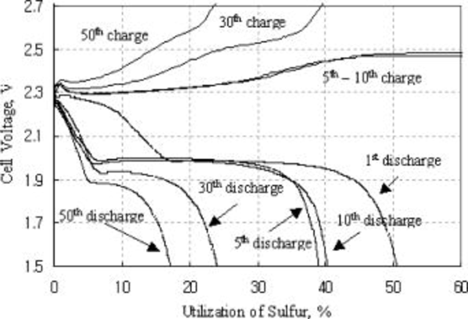
Figure 2. Charge and discharge voltage curves of type A cathode at room temperature.
SEM pictures of the surface of the type A cathode are shown in Fig. 3. Partly covered sulfur particles with another material that looks like smooth rocks of approximately 3-5 μm are readily noticeable all over the picture. Identification of the sulfur particles was done by comparison of the particle morphologies with those from an SEM picture (not shown here) of the neat sulfur powder material. Material that covers the sulfur particles and looks like fluffy amorphous-looking material that separates agglomerate masses up to 10 μm appears to be a composite mixture of the carbon particles and the binder material. The carbon particles should be dispersed partially in fine primary particles of 40 nm average size and partially in agglomerates of them inferring from the original particle morphologies of the carbon powder.
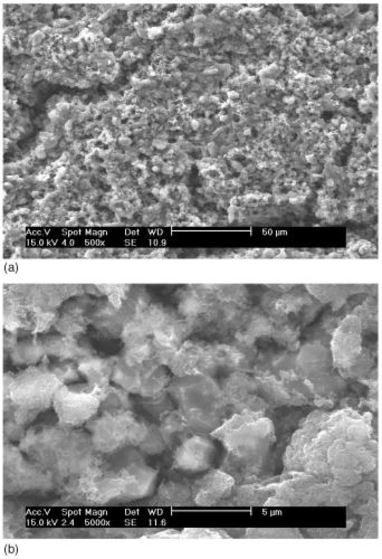
Figure 3. SEM images of type A cathode: (a, top) 500× and (b, bottom) 5000×.
During the cycling of the Li/S battery, structural changes occurred in the sulfur cathode. These structural changes have been obtained from SEM studies of cycled electrodes. Development of many microcracks or ruptures of the electrode matrix are observed as early as after ten cycles as shown in Fig. 4, although the ruptures themselves may not necessarily mean electrical isolation. Partial collapse of the carbon matrix structure is indicated in the cross-sectional view of the cycled cathode as shown in Fig. 5b, although such indication is not unequivocal. Such structural damage appears to become worse as cycling progressed, as shown in Fig. 5.
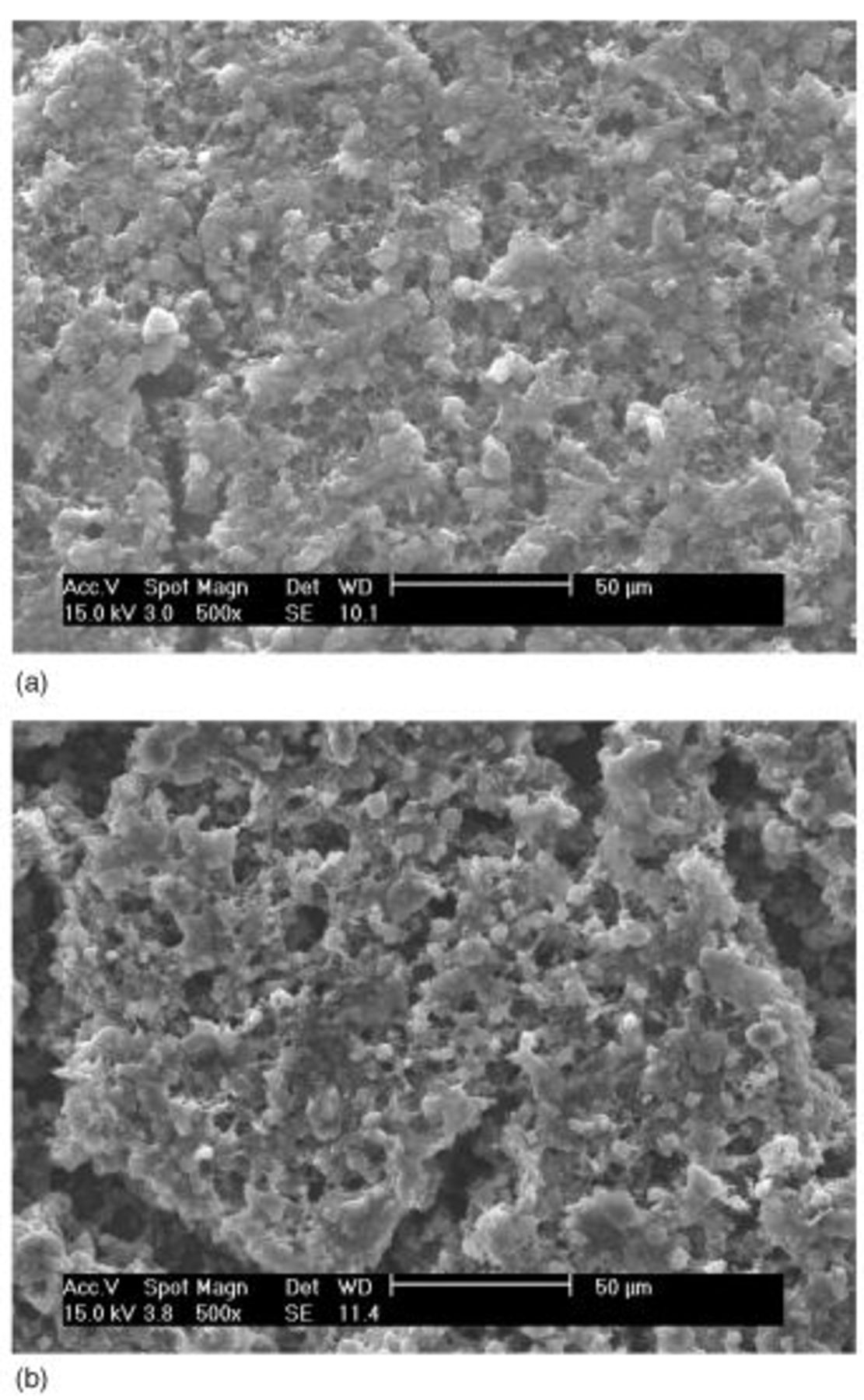
Figure 4. SEM images of the surface of fully discharged type A cathode: (a, top) 1st and (b, bottom) 50th cycle.
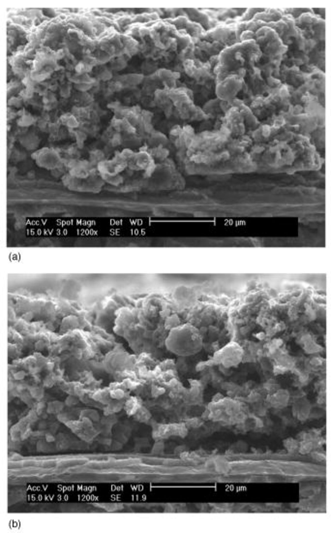
Figure 5. SEM images of a cross section of fully discharged type A cathode: (a, top) 1st and (b, bottom) 50th cycle.
As observed from these results, it is not difficult to imagine that the overall carbon matrix structure of the cathode is rather fragile when all the solid sulfur (84 wt %) that occupies the major fraction of the cathode volume dissolves away. Such a fragile carbon matrix structure is mainly due to the high content of sulfur to make a high-energy-density cathode (large volume of sulfur), unlike low-energy-density electrode structures reported earlier7 9 whose sulfur content, and therefore the volume of sulfur, is low. If a part of this carbon matrix is broken into pieces of various sizes and the broken pieces loose electrical contact to the main current-collecting structure, the active electrode surface decreases proportionally to the amount of electrically isolated pieces.
The cross-sectional views of the electrode after initial discharge and after 50 cycles were studied in further detail using an FIB imaging system. Narrow slots approximately 5 μm wide and 10-15 μm deep were dug out on the surface of the cathode by scanning the Ga ion beam at a slow rate. Figure 6 and 7 are the FIB secondary electron image from a slant angle viewing the cross-sectional area as well as the electrode surface in part. Formations of sulfur-rich layer (suspected  which cover the surface of the cathode and the pores of carbon matrix are observed after the initial discharge, as shown in Fig. 6. This layer might be responsible for relatively low utilization (50%) even at the first discharge by cutting out the progress of discharge reaction prematurely. Structural reorganization showing possible isolations of carbon masses as well as formation of large voids inside the electrode is evident after cycle tests, as shown in Fig. 7. The carbon matrix is abruptly rusted compared to the observed morphology in Fig. 6, and there the micropores (approximately 500 nm in size), which might be generated by electrode volume change, in the sulfur-rich-phase carbon layer were abruptly generated as shown in Fig. 7b.
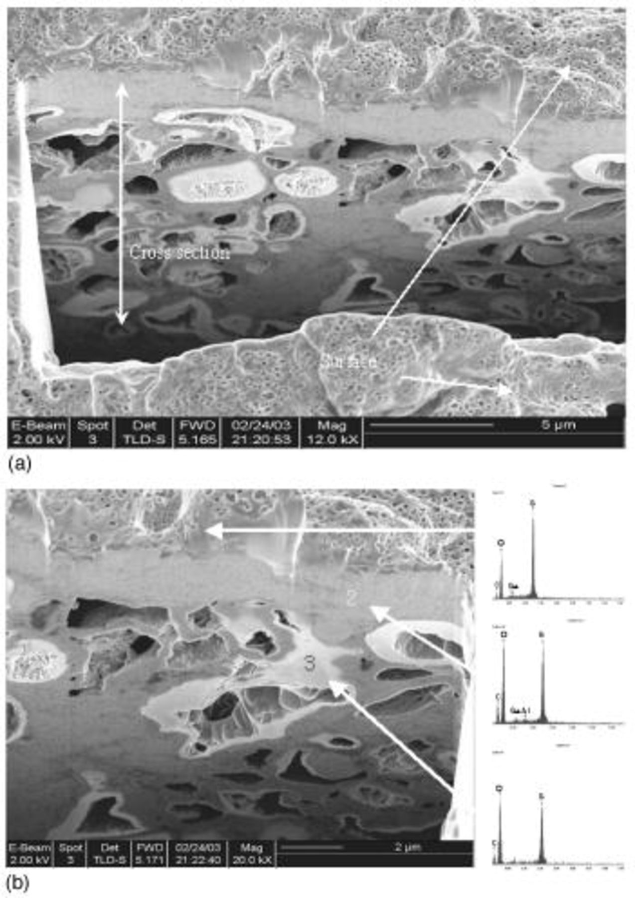
Figure 6. Cross-sectional SEM images of type A cathode after 1st discharge using FIB: (a, top) magnification of 12,000× and (b, bottom) 20,000× image with locally detected EDS data. (Ga peak is sourced by Ga ion beam for sample treatment with FIB.)
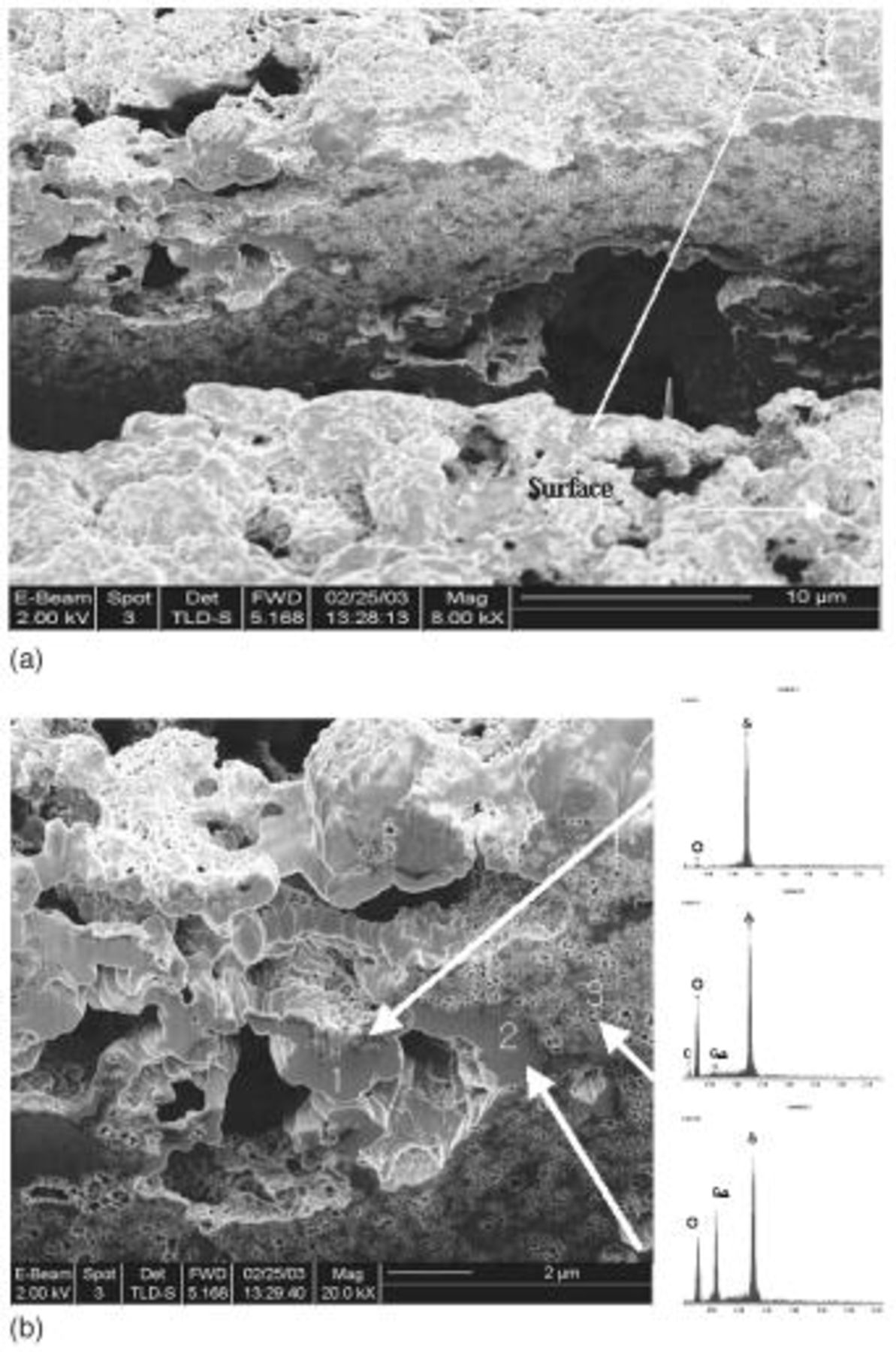
Figure 7. Cross-sectional SEM images of fully discharged type A cathode after 50 cycles using FIB: (a, top) magnification of 12,000× and (b, bottom) 20,000× image with locally detected EDS data. (Ga peak is sourced by Ga ion beam for sample treatment.)
Relative amounts of sulfur and carbon (in weight percentage) at the surface of the electrode estimated from EDX data are plotted vs. various numbers of cycles in Fig. 8. The observation of high THF-insoluble sulfur concentration on the electrode was decreased with increase of cycling and the solid reduction product loaded with sulfur on carbon matrix was detected as  phase from XRD results (Fig. 9a). The content of S at charge state is increased with the increase of cycle number, which might be
  phase based on the XRD result. This indicates that the solid sulfur layer which might be suspected electrochemically irreversible
  phase8 is continuously accumulated and then saturated in the carbon matrix with increasing cycle.
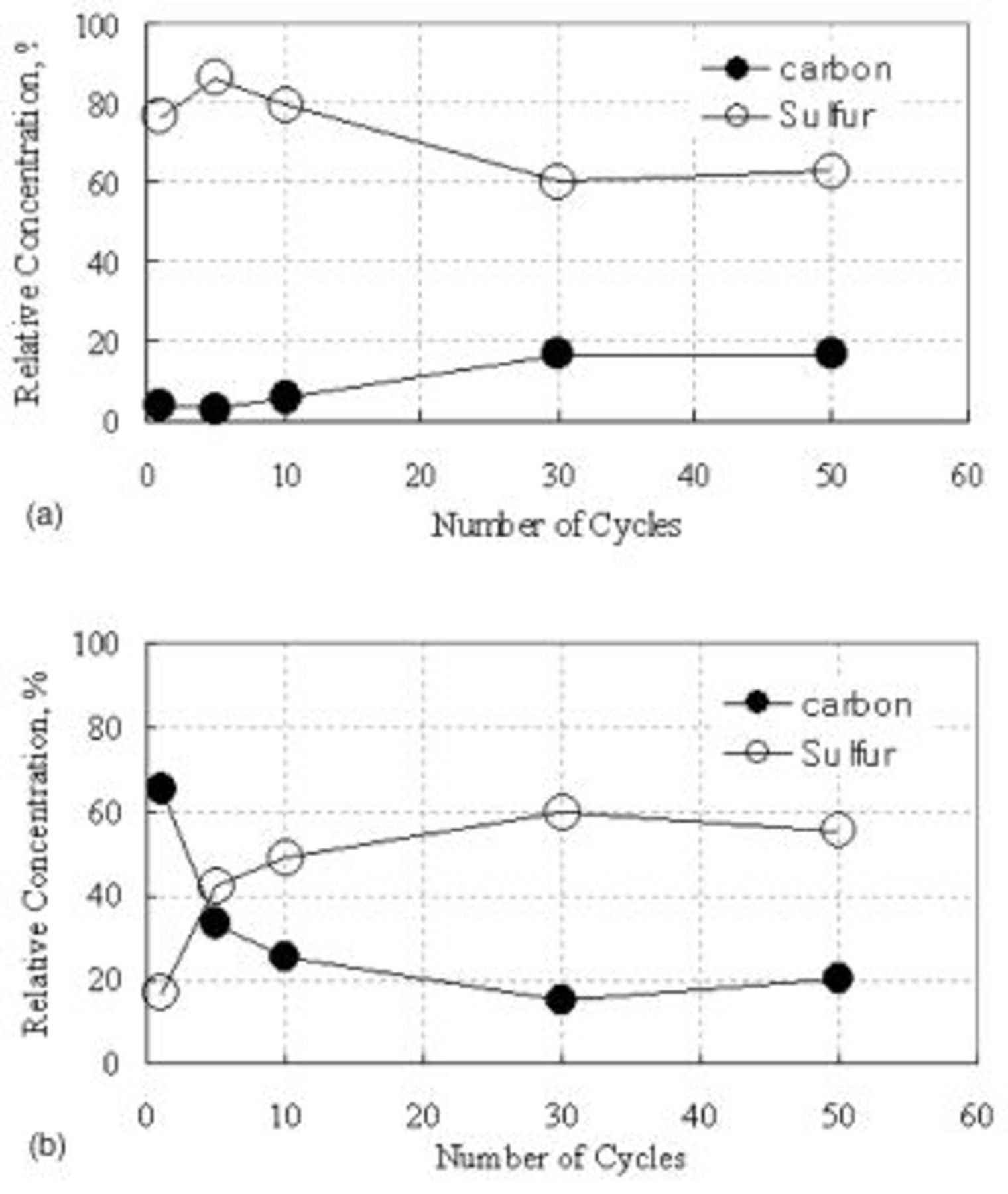
Figure 8. Relative content (by EDS) of sulfur and carbon at the surface of type A cathode after full (a, top) discharge and (b, bottom) charge after various numbers of cycles.
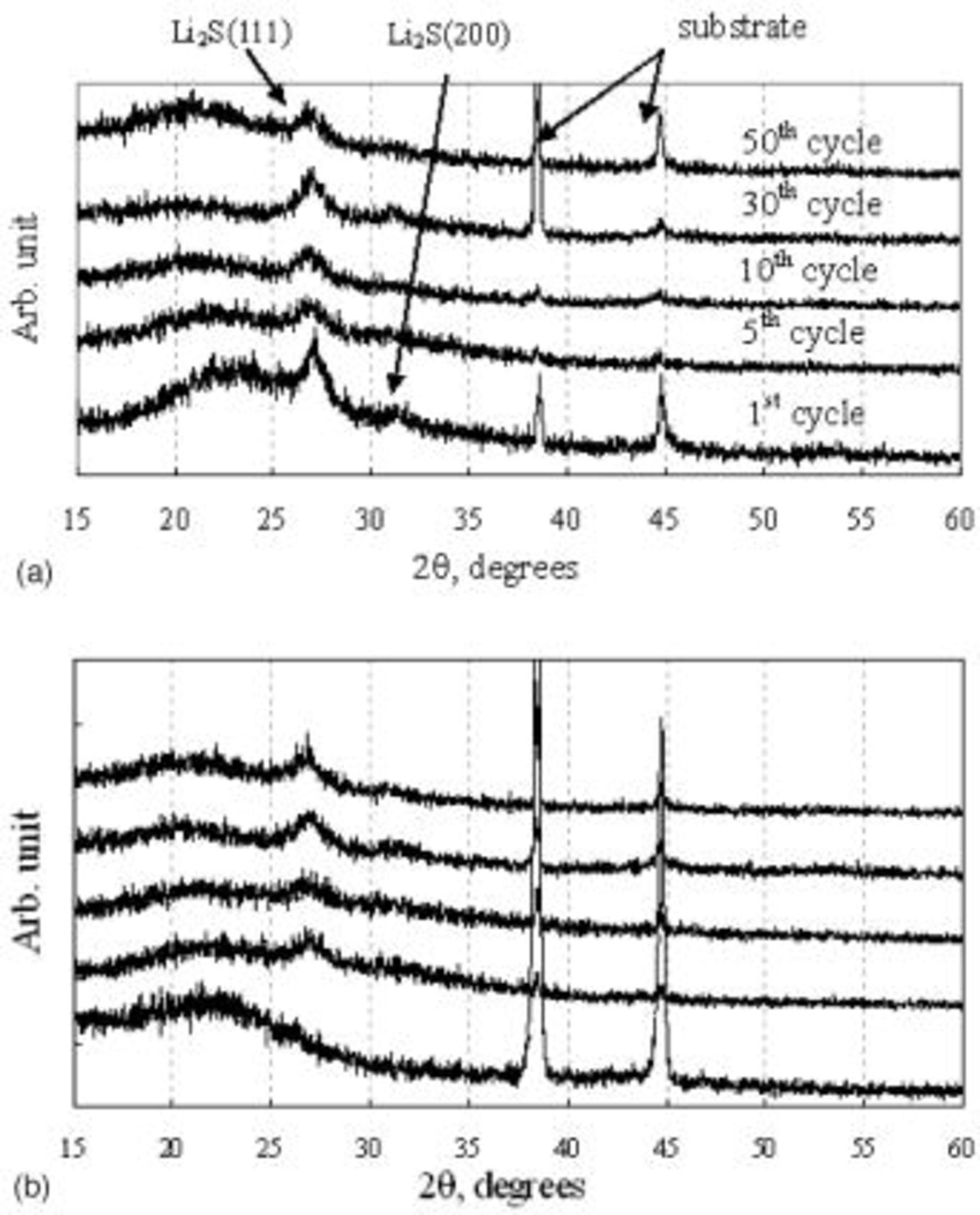
Figure 9. XRD patterns of type A cathode after full (a, top) discharge and (b, bottom) charge after various numbers of cycles.
From these results it can be deduced that the mechanical stress induced by volume change caused by redox reaction of sulfur and lithium is easily accommodated in the electrode with a high quantity of sulfur because of its fragile carbon matrix structure, which results in the enhancement of structural failure and the increase of irreversible  on the carbon matrix, and can explain the abrupt capacity fade of Li/S battery with the high-sulfur-contented cathode.
Type B cathode.—
SEM pictures of the surface of the type B cathode are shown in Fig. 10. Unlike the type A cathode (Fig. 3), all sulfur particles in type B appear to be fully covered by the carbon-binder composite material much more uniformly than in type A. The resulting carbon matrix structure of the cathode appears to be sturdy enough to keep the matrix structure substantially unchanged, even after all the solid sulfur (84% of weight) dissolves away and reforms as  phase as shown in Fig. 11a. Such a stable electrode frame structure may be responsible for the drastically improved cycle performance of the type B cathode as shown in Fig. 12. Capacity fading from the 2nd cycle (approximately 530 mAh/g cathode) to the 400th cycle (280 mAh/g cathode) was gradual and smooth without any abrupt change (cf. Fig. 1) with a fading rate of less than 0.12% per cycle. The overall carbon matrix structure of this cathode was maintained without gross damage even after 400 cycles, as shown in Fig. 11 and 13, unlike the type A electrode after 50 cycles (Fig. 5b and 7).
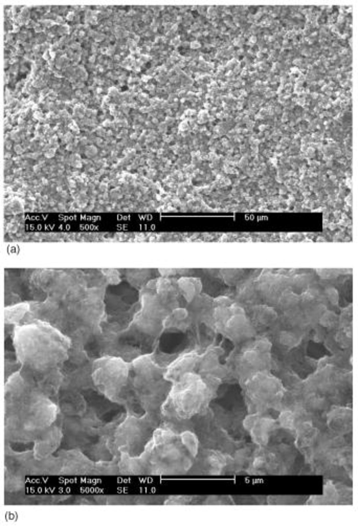
Figure 10. SEM images of the surface of type B cathode: (a, top) 500× and (b, bottom) 5000×.
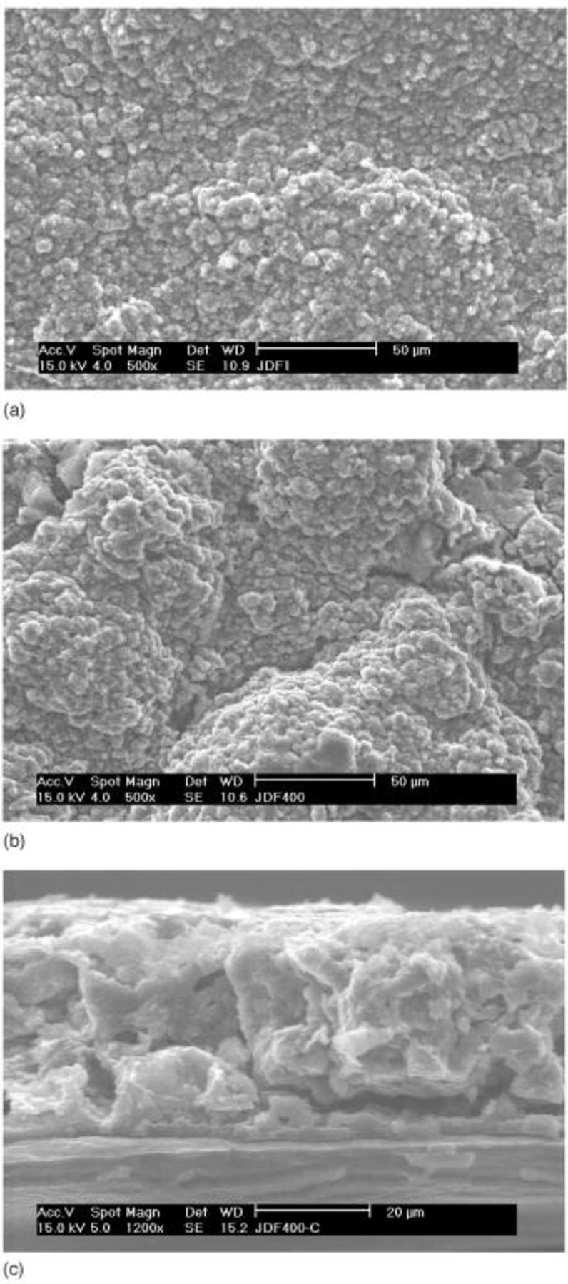
Figure 11. SEM images of fully discharged type B cathode: (a, top) surface after 1st discharge, (b, middle) surface after 400 cycles, and (c, bottom) cross section after 400 cycles.
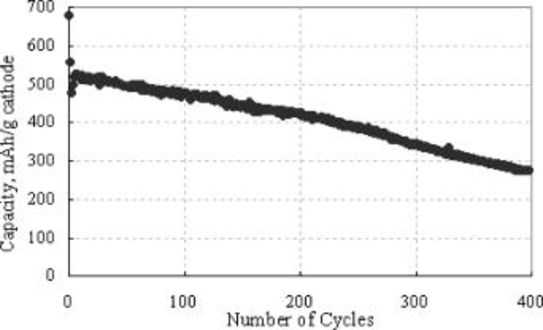
Figure 12. A plot of type B cathode capacity vs. number of cycles.
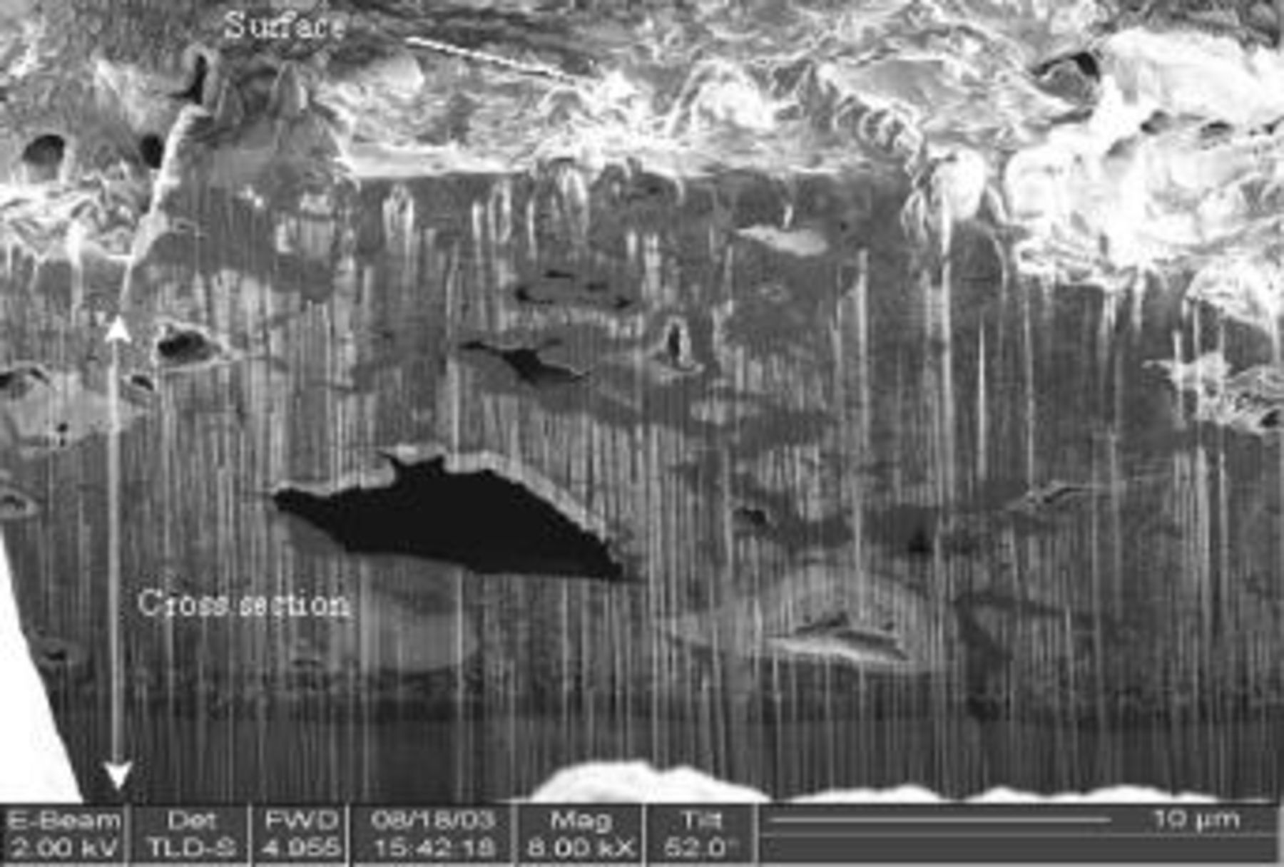
Figure 13. Cross-sectional SEM images of type B cathode after 400 cycles using FIB (8000×).
Charge and discharge curves of the type B cathode after various numbers of life cycles are shown in Fig. 14. The relative capacity values of the upper discharge plateau to those of lower plateau after the first cycle are much larger than those for the type A electrode (Fig. 2). The upper plateau capacity of the type B cathode decreased as the overall capacity decreased, unlike the type A cathode. Decrease in the lower discharge plateau voltage and increase of charge voltage of the type B cathode with cycling was much less than those of the type A cathode, indicating that the rate of electrode polarization increase with cycling is much reduced with the former compared with the latter.
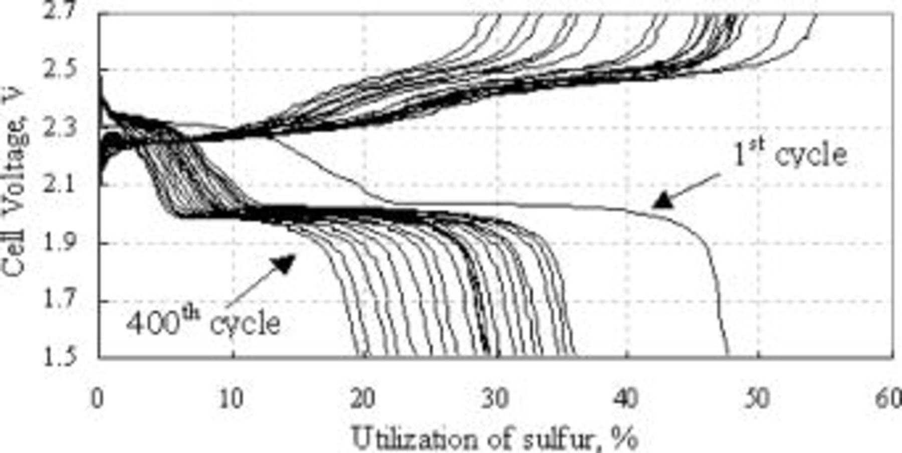
Figure 14. Charge and discharge voltage curves of type B cathode at room temperature after various numbers of cycles recorded every 20 cycles.
With the results discussed, it is speculated that the rapid capacity fading with cycling observed in Fig. 1 and 2 for the type A cathode might be due to structural damage of the carbon matrix in the cathode after a few discharge cycles decreasing the active carbon electrode surface by electrical isolation of carbon particles. Such damage might occur when the structurally weak carbon particle matrix, that is due to incomplete coverage solid sulfur particles by the carbon-polymer composite as well as nonuniform distribution of it (Fig. 3), collapses as the supporting solid sulfur particles disappear by dissolution during initial discharge. The damage process might continue with subsequent cycling of the cell, resulting in structural failure of the carbon contact and subsequent formation of irreversible  Such damage would reduce the active electrode surface and increase the true current density, accelerating the capacity fading process, particularly of the lower plateau, due to rapid structural failure of the carbon matrix and accumulation of irreversible
  deposits on the failed electrode surface, as observed by rapid decrease in the capacity and voltage of the lower discharge plateau with cycling (Fig. 2). Relatively small and constant (cycle-independent) capacity (5% S utilization) of the upper plateau of the type A cathode might be due to the open pore structure with large pore size of the electrode. The type A open pore structure should allow fast diffusion of the highly oxidized polysulfide species out of the cathode matrix into bulk electrolyte as they are produced by the charge reaction. The electrode structure might be able to contain only a steady-state amount of the oxidized species that corresponds to the observed capacity (5% S utilization) of the upper plateau away from diffusion in the constant current charging condition of relatively low rate (0.1 C). The diffused-out oxidized species would go to the counter Li electrode to be re-reduced.
The type B cathode contained a larger amount of the carbon and binder material in unit volume of the electrode structure than type A, because the former was 30 μm thick whereas the latter was 50 μm thick, while the loading levels of these two cathodes are the same. The carbon matrix of the type B cathode after all the original sulfur particles dissolved away should be sturdier than that of type A. The pore structure of the type B carbon matrix was more uniform and finer than that of type A, as shown in Fig. 10. Therefore, improved performance of the type B cathode is apparently due to the uniform pore structure of the carbon matrix with smaller pores as well as its sturdier structure than that of type A. The carbon matrix of the type B cathode was apparently sturdy enough to maintain its structural integrity without a gross failure even after 400 cycles, as shown in Fig. 12 and 13.
Conclusions
The prevailing mechanism of the capacity fading shown in one (type A) of the present cathodes might be the possible loss of the active electrode surface and subsequent formation of the irreversible  layer at the surfaces of the carbon particles by physical separation (by crack formation) of the carbon particle matrix. The rate of capacity fading on cycling reduced substantially and significantly by an improved fabrication technique of the cathode (cf. Fig. 12 vs. Fig. 1) that gives improved structural integrity and uniform pore structure of the carbon matrix. A cathode (type B) fabricated by the improved technique cycled over 400 cycles without any gross structural damages in the electrode and with much improved capacity retention over a previous fabrication method (type A), although future improvements in cycle life are needed for practical application of the cathode.
Samsung SDI Company assisted in meeting the publication costs of this article.