
Abstract
Reduced operating temperatures  of solid oxide fuel cells (SOFCs) may enable the use of inexpensive ferritic steels as interconnects. Due to the demanding SOFC interconnect operating environment, protective coatings are gaining attention to increase long-term stability. In this study, large area filtered arc deposition and hybrid filtered arc deposition-assisted electron beam physical vapor deposition technologies were used to deposit two-segment coatings with
  -based bottom segment and
  top segment. The bottom segment serves as a diffusion barrier and bond segment, while the top segment is meant to increase electrical conductivity and inhibit Cr volatility. Coatings were deposited on ferritic steel and subsequently annealed in air for various time intervals. Surface oxidation was investigated using Rutherford backscattering spectrometry, scanning electron microscopy, and energy-dispersive spectrometry analyses. Cr volatilization was evaluated using a transpiration apparatus and inductively coupled plasma-mass spectrometry analysis of the resultant condensate. Electrical conductivity (area specific resistance, ASR), was studied as a function of time using the four-point technique. Significant improvement in oxidation resistance, Cr volatility, and ASR were observed in the coated versus uncoated samples. Transport mechanisms for various oxidizing species and coating diffusion barrier properties are discussed.
Export citation and abstract BibTeX RIS
Planar solid oxide fuel cells (SOFCs) are increasingly promising candidates for future energy conversion due to their inherently high efficiencies and decreasing environmentally sensitive emissions.1 Typical anode-supported planar SOFC design and operation are described elsewhere.2 During operation, the planar SOFC interconnect component realizes simultaneous dual atmosphere (wet reducing and oxidizing) exposure up to  . The interconnect/electrode and interconnect/seal interfaces must exhibit chemical, thermal-mechanical, and electrical stability throughout the desired SOFC stationary device lifetime of
  , while enduring a large number of thermal cycles.3 High-temperature metallic alloys have received attention for use as intermediate-temperature
  SOFC interconnects due to their higher relative toughness and formability and much lower costs compared to commonly used ceramic alternatives. Of particular interest are high Cr content, ferritic stainless steels, which exhibit compatible thermal expansion coefficients with other SOFC components, but form electrically resistive thermally grown oxide (TGO) scales when exposed to the complex SOFC operating gases. TGO scales can introduce adverse chemical and thermal-mechanical incompatibilities with adjoining SOFC components through deleterious species volatilization, interdiffusion, and thermal-mechanical stresses. A thorough investigation of several heat-resistant alloys concluded that, for improved oxidation resistance and electrical conductivity, either new alloys need to be developed or surface engineering of existing alloys is required.4 Among the candidates in the former category is Crofer 22 APU, a ferritic stainless steel
  , with engineered additions of Mn, Ti, and La (available from ThyssenKrupp VDM).5 This special high-temperature stainless steel is characterized by the formation of a stable and electrically conductive
  oxide surface layer during SOFC cathode gas-phase exposure. However, continued TGO scale growth (dominated by an underlying
  layer) during extended exposures may create increased electrical resistance and other SOFC incompatibilities.6
The present work is focused upon further enhancement of Crofer 22 APU by depositing surface coatings using large area filtered arc deposition (LAFAD) or hybrid filtered arc deposition-assisted e-beam physical vapor deposition (FAD-EBPVD) processes.7, 8 Various single and dual-segment LAFAD and FAD-EBPVD coatings from the  system have been applied to sample coupons of Crofer 22 APU alloy in an attempt to improve its SOFC-interconnect performance characteristics. This research is aimed toward understanding the influence of coating characteristics (thickness, structure, phase, and chemical composition) on long-term thermal-mechanical and chemical stability of interconnect/cathode interface during SOFC exposure. Related research in this area includes deposition of conductive oxide and nitride coatings using various techniques.9–14
Experimental
Coating architectures and plasma vapor deposition pro cesses
A broader goal of this research is to enable the use of inexpensive alloys for SOFC interconnects by developing a coating material system and deposition process to ensure electrical, chemical, and thermal-mechanical compatibility with other SOFC stack components, throughout the device's lifetime. Toward this end, the dual-segment coating approach, illustrated in Fig. 1, has been investigated.
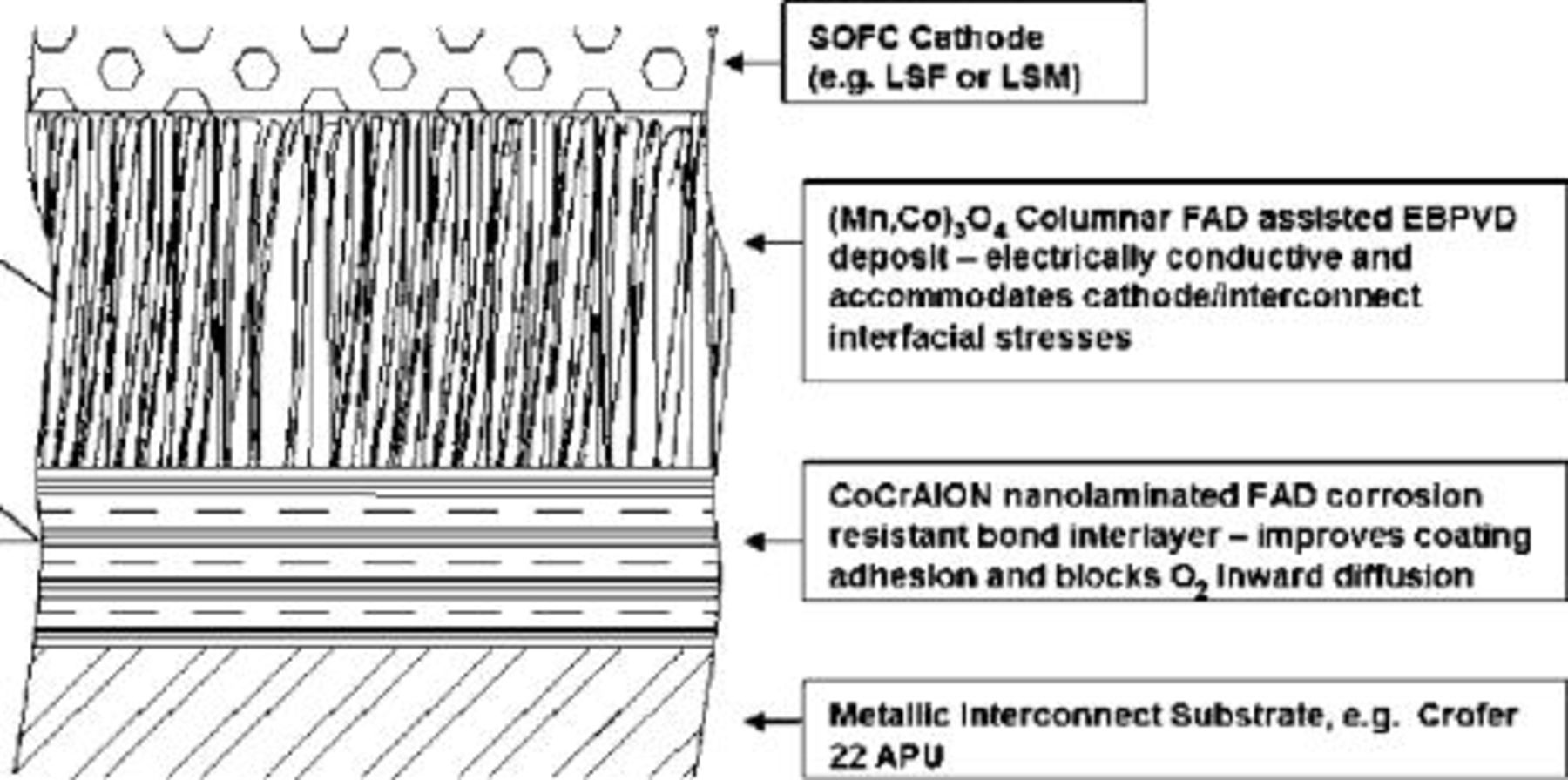
Figure 1. Dual segment, hybrid coating approach.
The use of coatings to improve oxidation resistance on metal alloys has been known for many years. The LAFAD  bottom-segment coating system was selected for this study due to previously demonstrated oxidation and wear resistance at temperatures up to
  .12–14 Nanolayered structures consisting of alternating
  and
and  sublayers have been investigated with the goal of revealing the application-specific efficacy of this surface treatment.
The FAD-EBPVD  system was investigated as a top segment coating because of its SOFC cathode compatibility, its recently reported success in reducing ASR, as well as its anticipated reduction in Cr volatilization.15–17
Two primary coating architectures were investigated: one with the top  segment only
  , and one with both the bottom
  bond coating segment and top
  segment present
  . Results from long-term
  oxidation in air at
  , ASR, and Cr volatility from the two unique coated samples, in addition to uncoated samples are presented here, together with an interpretation of the significance of these results.
The single and dual-segment coatings were deposited on  thick mechanically lapped and polished (
 nominal roughness by LapRight, Inc.) substrate coupons of Crofer 22 APU by Arcomac Surface Engineering, LLC using patented filtered arc plasma source ion deposition (FAPSID) technology.7 The universal FAPSID surface engineering system employs a hybrid combination of LAFAD plasma sources with conventional e-beam evaporators, unbalanced magnetrons, thermal resistive evaporators, and low-pressure chemical vapor deposition (CVD) sources all integrated in the one plasma processing chamber layout (Fig. 2). This allows for deposition of virtually any PVD and low-pressure CVD coatings in highly ionized filtered arc plasma environment. The LAFAD dual-filtered arc plasma source utilizes rectangular plasma-guide chamber with two rectangular deflecting coils installed on opposite sides, with electron beam evaporators within the chamber, as shown in Fig. 2. In this design, two primary cathodic arc sources utilizing
  and
and  targets are placed opposite each other on the sidewalls of the plasma-guide chamber, surrounded by rectangular deflecting coils, and separated by an anodic baffle. The LAFAD vapor plasma source uses a superimposed deflecting magnetic field to turn the metal ion flow
  toward the deposition chamber and substrates. More massive droplets of target material and unionized metal vapor atoms follow straight trajectories and are captured on baffles, resulting in droplet-free 100% ionized metal vapor plasma yield for deposition of
  bottom-coating segment. A set of scanning magnetic coils allows the ion plasma jet to be rastered, thereby promoting uniform coverage of large surface areas.8 When the deflecting magnetic field coils are off, the LAFAD source can be employed as an effective, large area plasmatron, ionizing vapors from other conventional sources and the gaseous environment within the chamber. During the FAD-EBPVD deposition of the
  upper-coating segment, the LAFAD source is used as a powerful emitter of electrons, effectively ionizing the
  vapor and reactive oxygen gas atmosphere, aiming to densify the resultant coating. In this gaseous plasma ionizing mode the deflecting magnetic subsystem of the filtered arc source is deactivated and the cathodes of the primary arc sources serve as electron emitters while the distant auxiliary anode accepts the electron current. Ionization rate in the auxiliary arc plasma discharge reaches up to 50%.8 The metal vapor flow from the e-beam evaporator is also substantially ionized via collisions with the auxiliary arc electrons.
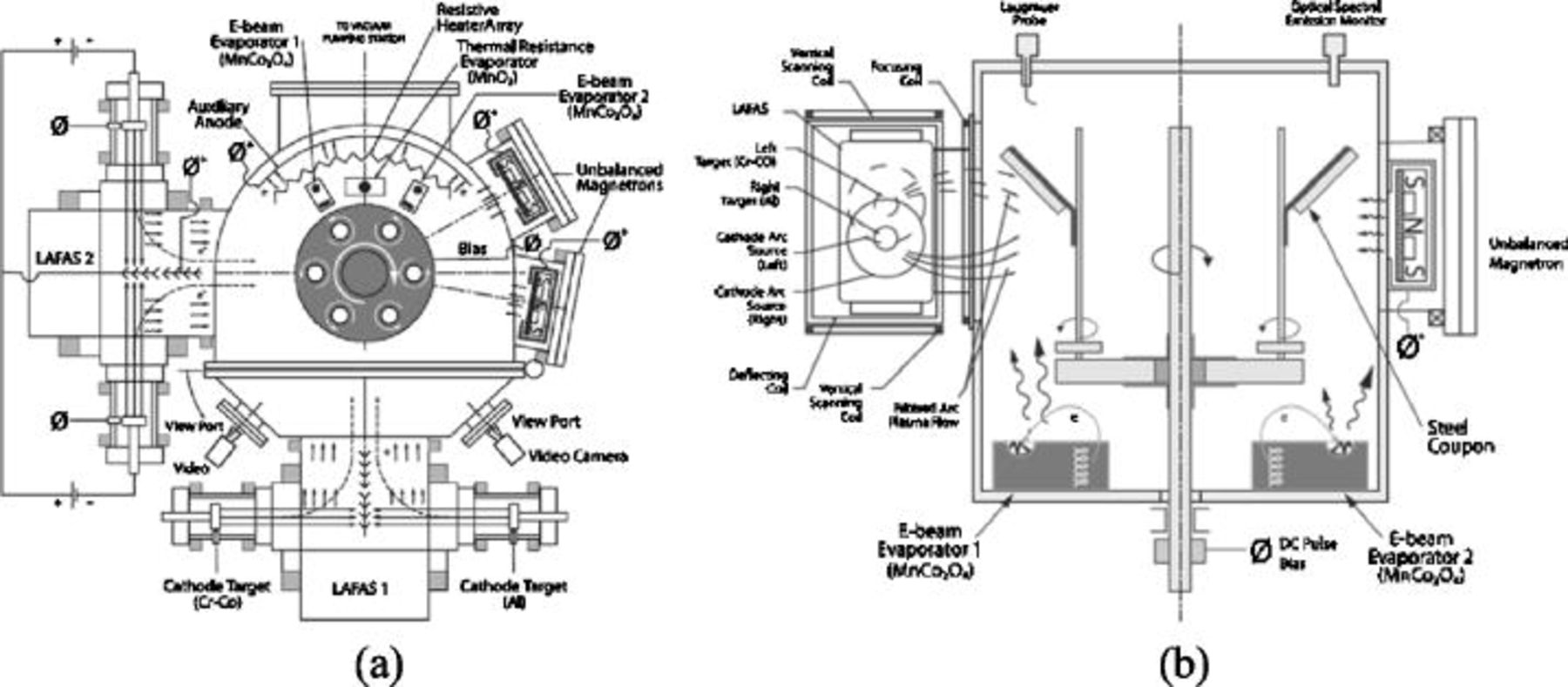
Figure 2. Schematic illustration of the FAPSID surface engineering system, showing (a) top view; and (b) side view.
The substrates were mounted on pedestals distributed about the outer rim of a rotating carousel in the FAPSID chamber. Substrate temperature during deposition of the bottom  coating segment was about
  . Substrates were first cleaned in an Ar plasma at
  for
for  , followed by
  of high voltage
 metal ion bombardment stage in Ar at
  .
.  and Al ions were then deposited in an
  :
:  reactive gas atmosphere with
  addition at
  . In addition, the preliminary experiments were conducted with different
  ratios to study oxidation kinetics of these
  -based coatings. The applied medium frequency (MF) substrate bias was set at
  with frequency of
  . With both target sources on and substrate rotation engaged, the substrates were successively exposed to
  , then Al ions, in a mixed
  reactive gas atmosphere, resulting in nanometer-size bilayers of
  . Thickness of the individual bilayers in the coating was controlled by the rotation speed of the carousel, deposition time, and total coating thickness, and was estimated at
  for the coatings considered here. The FAD-EBPVD
  upper-segment coating was deposited by evaporating a sintered
  spinel target pellet using a standard
  electron beam rastered over the target, with an emission current of
  . The pressure during the FAD-EBPVD process was
  in a reactive oxygen gas atmosphere with
  addition. During the evaporation, the LAFAD plasma source was set in ionization auxiliary arc discharge mode (deflecting magnetic field off), with an auxiliary arc current of
  . The substrate bias during deposition of this layer was set at
  .
.
Coating properties characterization
Coating adhesion was assessed by means of the Mercedes indentation test using a Rockwell C indenter with  load. Radial cracks surrounding the indentation indicate good coating adhesion. Radial cracks with localized delamination indicate fair adhesion, and concentric cracks around the indentation with large area delamination indicate poor coating adhesion.18
Oxidation of the sample coupons (in Bozeman, MT air) was carried out using a standard furnace operated with no control of humidity or air circulation. Measurements of area specific resistance (ASR) were made in air at  using standard procedures with Ag paste electrodes on preoxidized samples as a function of time and temperature for coated and uncoated Crofer 22 APU coupons.2, 4
Subsequent to varying exposure times, sample cross sections for microscopic analysis were prepared by epoxy-mounting, sectioning, and polishing. Scanning electron microscopy/energy dispersive spectrometry (SEM/EDS) analysis was performed using a JOEL SEM model S4700.
Ion beam analysis of the coated samples was performed using the  tandem accelerator at the Environmental Molecular Sciences Laboratory (EMSL) at Pacific Northwest National Laboratory (PNNL) in Richland, WA, and the
  van de Graaff accelerator at Montana State University. The latter was used for beams of
  and
and  up to
up to  , while the former provided higher energy
  beams to analyze thicker coatings, and
  beams for nuclear reaction analysis of the O and N concentrations, using the
  and
and  reactions. Spectra were typically collected after total oxidation periods of 1, 4, 9, 16, and
  at
at  in lab air with no control of humidity. The samples were removed from the oven for ion beam analysis, and were thus subjected to thermal cycling at a rate of
  that might have adversely affected the coatings. Composition profiles were determined by comparing SIMNRA computer simulations of the spectra with the original data.19–21
Cr volatility was investigated using a transpiration apparatus developed at Lawrence Berkley National Laboratory. To prevent Cr volatility from the uncoated side of the coated coupons, all samples (including uncoated) were first electroplated with  Ni on one (uncoated) side (Omni Metal Finishing, Inc.). The samples were preoxidized in air at
  for
for  prior to
  exposure to
  air with
 at
at  . The condensate from the effluent gas was then analyzed for its Cr content using inductively coupled plasma-mass spectrometry (ICP-MS).
Results and Discussion
Ion beam analysis was used to characterize the oxidation resistance and diffusion characteristics for several candidate bond coatings coming from the  system. Figure 3 shows the results for the effectiveness of a
  bond coat, with no top coat and three different
  ratios in the as-grown coatings. The surface of the coating is at the left side in each profile, and the steel substrate can be seen at the right with its characteristic high Fe concentration. The depth scale unit
  is characteristic of Rutherford backscattering spectrometry (RBS) measurements, and for this case corresponds to approximately
  . The vertical scale is a percentage concentration, based on the assumption that the individual concentrations add to 100%. No measurement of hydrogen concentration was made for these coatings. The left column shows the composition for the three coatings as prepared with decreasing oxygen concentration from top to bottom. The
  ratio for the coatings correlates well with the
  partial pressure ratio in the chamber during growth. The right column shows the concentration profile for each sample after
  of oxidation at
  in a tube furnace with laboratory air.
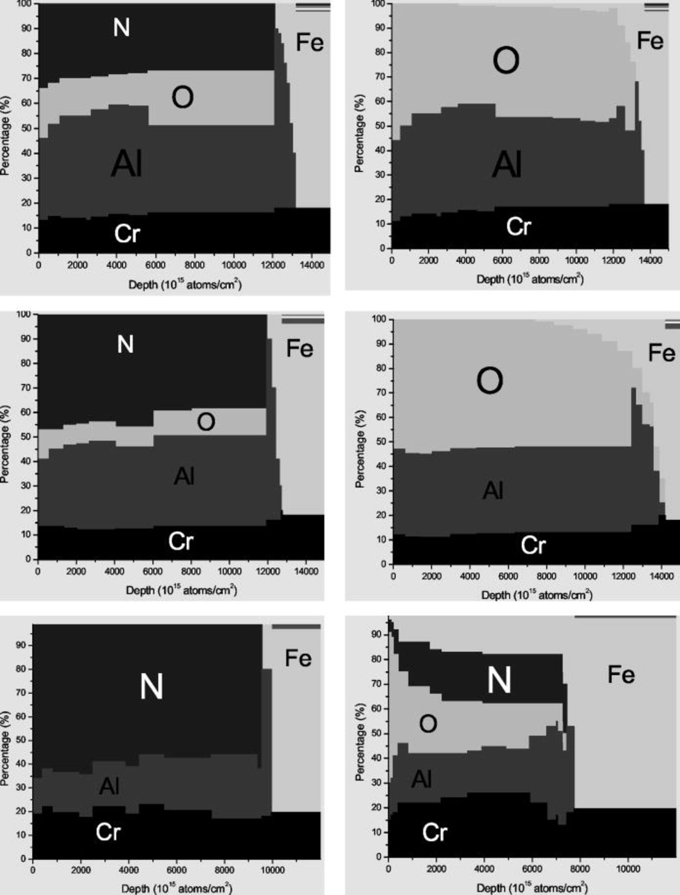
Figure 3. Profiles of concentration versus depth for three samples with (top to bottom) decreasing  ratios (left) before and (right) after
  oxidation at
  .
.
On bare steel (without protective coating), oxygen activity at the surface is essentially the oxygen partial pressure in ambient air, i.e.,  , if disregarding water vapor or the surface boundary diffusion layer, which is quite thin at
  . Given a sufficient Cr concentration in the steel, Cr is selectively oxidized and forms an external
  -based scale. Once
  is thermally grown into a dense, continuous surface layer, the oxygen activity at the scale/steel interface decreases, and the scale growth slows down and enters into a steady state. During this state, the scale continues to grow by Cr outward diffusion and oxygen inward diffusion across the thermally grown scale, with the Cr inward transport often dominating and the growth following a parabolic relationship.22 The continuous growth of the scale over long terms may lead to increased stress in the scale and in particular at the scale/steel interface, causing scale spallation and loss of protection against further environmental attack.
To improve the steel surface stability and resistance against environmental attack, protective coatings, such as a  , are applied onto the steel surface. First,
  coatings act as a diffusion barrier to oxygen inward diffusion and preferably also to outward Cr diffusion. Assuming the protective coating entirely inhibits the outward Cr diffusion, it can be deduced that the scale growth beneath the coating is limited by the inward flux of oxygen.22 Accordingly, the following relationship can be considered to describe the scale growth rate in the presence of protective diffusion barrier coating:
  , where
  is the growth rate of chromia TGO;
  is partial pressure of oxygen on the scale/cathode interface;
  is oxygen diffusion coefficient throughout the
  coating; and
  is coating thickness. A decreased inward flux of oxygen is expected to drastically mitigate the scale growth of the scale and thus to improve the surface stability of the steel. Second, the
  coating is expected to serve as a barrier against Cr outward diffusion with and without additional top segment
  , which serves exclusively as a Cr diffusion inhibitor. In the case of two-segment coating design, the bottom
  coating acts as a bond coat that is expected to improve the adherence between the alloy substrate and the outside surface, which serves as a Cr barrier. To be effective and function well, the protective or bond coat has to be free from defects, such as open pores or cracks.
The  -based bond coats with different
  ratios analyzed here behave very differently when subjected to the high-temperature oxidizing atmosphere (Fig. 3). Sample B9 with about 20% oxygen, as grown, lost almost all of the nitrogen in the coating, and shows only a small amount of Fe diffusion from the substrate into the coating, although it did not diffuse all the way to the surface after
  . Coating C9 contains about 10% oxygen concentration as grown. In marked contrast to sample B9, the nitrogen in sample C9 is almost completely replaced by oxygen after only
  of heating at
  , and the coating is more susceptible to Fe diffusion from the substrate into the coating. However, this coating did not show any Fe at the surface after
  of heating. For coating D9 there is no oxygen in the as-grown sample. The nitrogen in the coating is gradually replaced by oxygen, and is completely lost after
  of heating at
  . Diffusion of Fe into the coating begins after only
  of heating, and Fe has reached the surface of the coating after
  of heating. Based on the above results, we conclude that introducing oxygen during the coating growth process creates more effective diffusion barriers that slow down the diffusion of Fe from the substrate into the coating. Synthetic formation of TGO scales during coating growth, rather than as a result of diffusion during subsequent oxidation, results in a more stable bond coat on these steel substrates.
Figure 4 shows adhesion testing results for as-deposited coatings: (a) dual segment  coating, and, (b) upper segment
  only coating. The radial crack propagation from the indentation in Fig. 4a demonstrates the excellent adhesion of the dual segment
  coating system. The localized area coating delamination near the indentation in Fig. 4b indicates only fair adhesion of the upper segment
  coating, when deposited without the lower segment coating. These results indicate the substrate-coating adhesion promoting functionality of the dual segment coating architecture (with
  bond coating). This is likely because of the intense ion surface interaction during the initial coating deposition stage, resulting in significant ion implantation into the substrate and enhanced adhesion of the growing film.
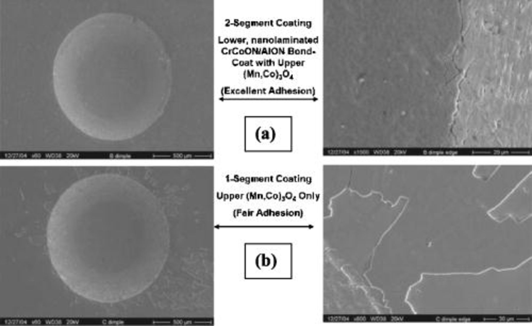
Figure 4. Adhesion (indentation) testing of as-deposited: (a) dual; and (b) single segment coatings on Crofer 22 APU.
On bare steel, scale spallation due to increased scale thickness is not an issue of compromised interfacial toughness. If the failure is just due to thickening, it is caused by an increase in stored elastic strain energy in the scale, due to an increase in scale volume. This causes the energy release rate driving scale debonding to become greater than the interfacial toughness (which is a measure of the interface's resistance to debonding). The ability of coatings to limit scale growth is critical and so deposition of defectless coatings is critical. Adding a coating to the chromia/steel system would generally increase the likelihood of spallation because of the addition of another residually stressed layer on top of the growing chromia scale. If, however, the coating reduces chromia scale growth rates, the net effect could be no change or, if the scale growth is significantly reduced, the effect could be beneficial in preventing spallation. The latter can be achieved by optimizing coating thickness as well as toughness at the coating/scale interface.23
Figure 5 shows surface SEM images before and after high temperature oxidation in air at  for over
  . Figure 5a and 5b is an image of the single, upper segment filtered arc assisted
  coating before and after
  oxidation in air at
  , respectively. Figure 5c and 5d is an image of the dual segment,
  coating system before and after
  oxidation in air at
  , respectively. The dual segment coating exhibits significantly finer surface microstructure compared to the single segment coating. This indicates a significant influence of the lower segment coating on the surface morphology and its evolution. Characteristics of the bond segment coating, including its amorphous or ultrafine crystalline nature, in addition to its diffusion-barrier properties, may be responsible for this occurrence, and are the subject of ongoing investigations.
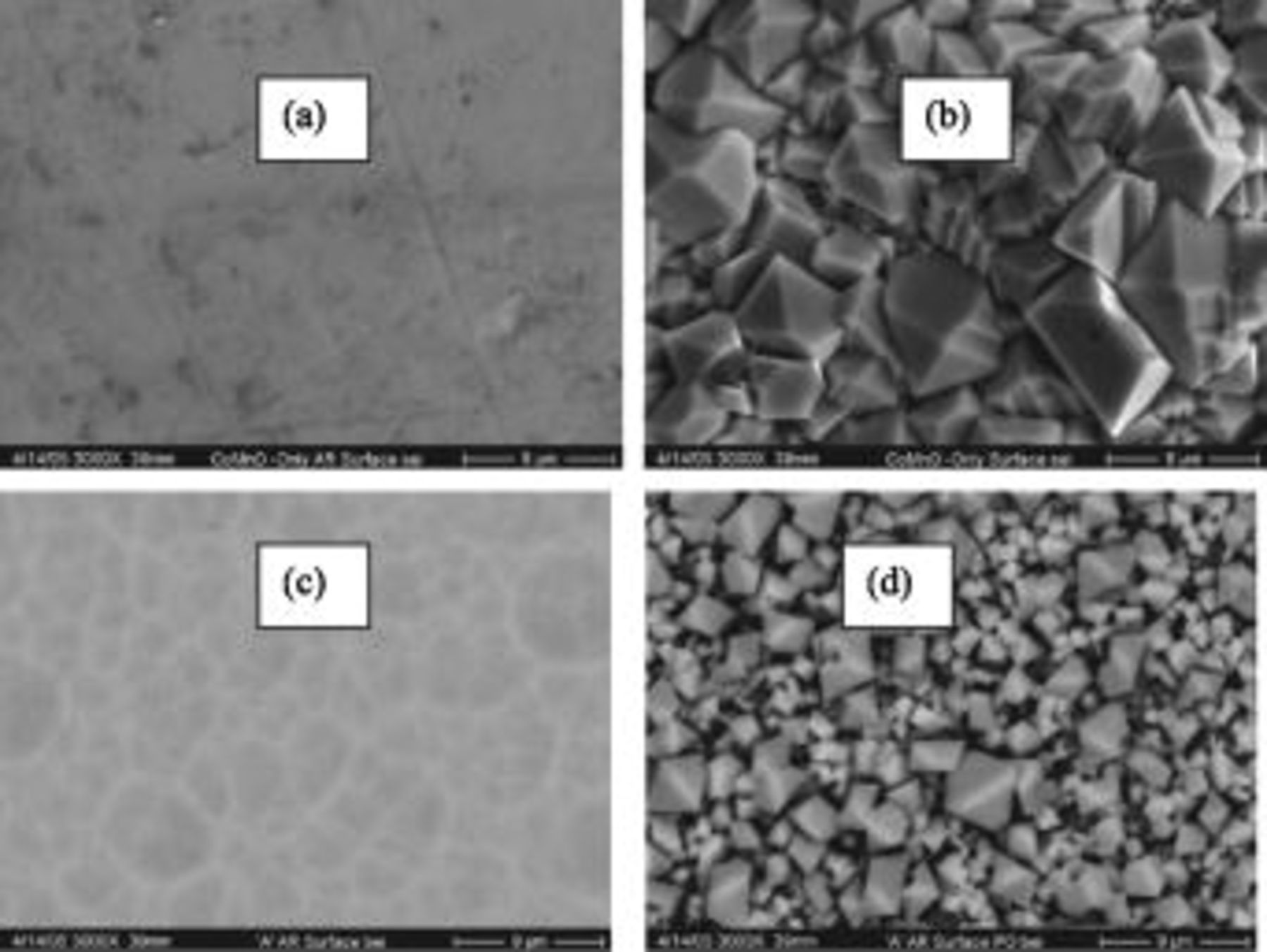
Figure 5. Surface SEM images demonstrating coating recrystallization behavior: (a) as deposited, amorphous or ultrafine polycrystalline  single segment coating; (b)
  single segment coating post-
 oxidation at 800°C; (c) as deposited, amorphous or ultrafine polycrystalline
  dual segment coating; and (d)
  dual segment coating post-
 oxidation at 800°C.
ASR testing was performed both at PNNL and MSU using Ag paste for electrical contact. Figure 6a shows PNNL data comparing uncoated and dual segment coated Crofer 22 APU. The ASR of the uncoated sample reaches a minimum after  , and rises steadily past
  after
after  . The ASR values of the dual segment coating continue to decrease below
  after over
  of testing. The spike in this data maybe associated with the coating recrystallization process shown in Fig. 5, which is currently under investigation. Figure 6b shows ASR testing results of FAD-EBPVD deposited
  compared to
  deposited at PNNL using conventional magnetron sputtering. Differences in ASR behavior between these coating techniques are not significant, with both achieving a similar minimum ASR value of
  with ASR slowly rising to
  after
after  . As the process times for conventional magnetron sputtered coating are an order of magnitude longer than that for FAD-EBPVD coating, the observation of ASR behavior similarity is promising. In addition, the FAD-EBPVD process may result in fewer coating defects and, therefore, improved diffusion-barrier properties compared with conventional coating deposition techniques. This would permit greater durability of the coating against the SOFC interconnect environmental attack.
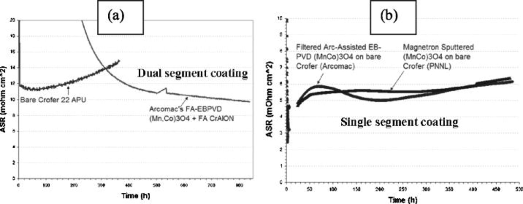
Figure 6. ASR testing results from PNNL.
ASR testing results at MSU from two coating systems and uncoated Crofer 22 APU are shown in Fig. 7. Spikes in the data represent thermal cycling events. The two coated samples display lower ASR values compared with uncoated Crofer 22 APU after  . ASR values for uncoated Crofer 22 APU continue to rise past
  after
after  , while coated samples display relatively stable ASR behavior, with values below
  after
after  . The upper segment coating alone had the lowest ASR values, while the dual segment coating exhibited the most ASR stability. The continued growth of a chromium-rich scale under the single, upper segment coating can explain the continued rise in ASR. The gradual decrease in ASR observed in the dual segment coating is likely due to interfacial and surface evolution during the test. ASR for both single and dual segment coated samples appear to rise after some time; however, the dual segment coating rises significantly slower. This is presumably due to the slower TGO scale growth of the dual segment coating compared with the single segment coating, which lacks the diffusion barrier attributes of the bond segment coating. In general, results from both PNNL and MSU ASR investigations are in good agreement, and indicate significant improvement afforded by the coatings studied here. Evidence for Ag paste interaction with both coated and uncoated samples during testing is currently under investigation.
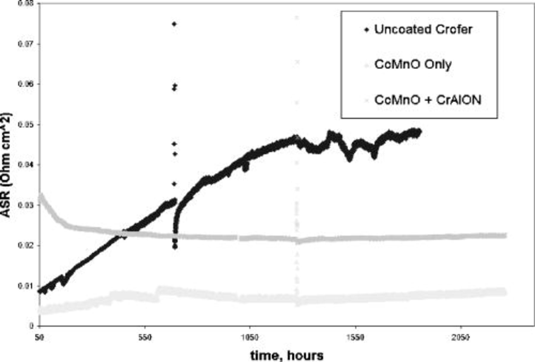
Figure 7. ASR testing results from MSU.
An SEM image with EDS line profiles for individual elements of the dual segment coating after  oxidation in air at
  is shown in Fig. 8. The composition of the upper segment layer is
  , with negligible Cr content. The coating appears dense and well-adhered to the substrate material. Co observed in the bottom coating segment can be attributed to both the LAFAD
  coating deposition process and the inward diffusion from the upper FAD-EBPVD
  segment. In comparison, Mn observed in the bottom segment can be attributed to the inward diffusion from the upper coating segment and outward diffusion from the Mn-containing Crofer substrate. The SEM cross section in Fig. 9 shows the dual segment coating after ASR testing for more than
  . EDS line scan results displaying elemental depth profiles overlay the SEM image. The coating thickness and composition before and after ASR testing remain similar and coating delamination was not observed. Again, negligible Cr content is found at top of the deposited layer, thus demonstrating the coating's effective reduction in Cr surface transport.
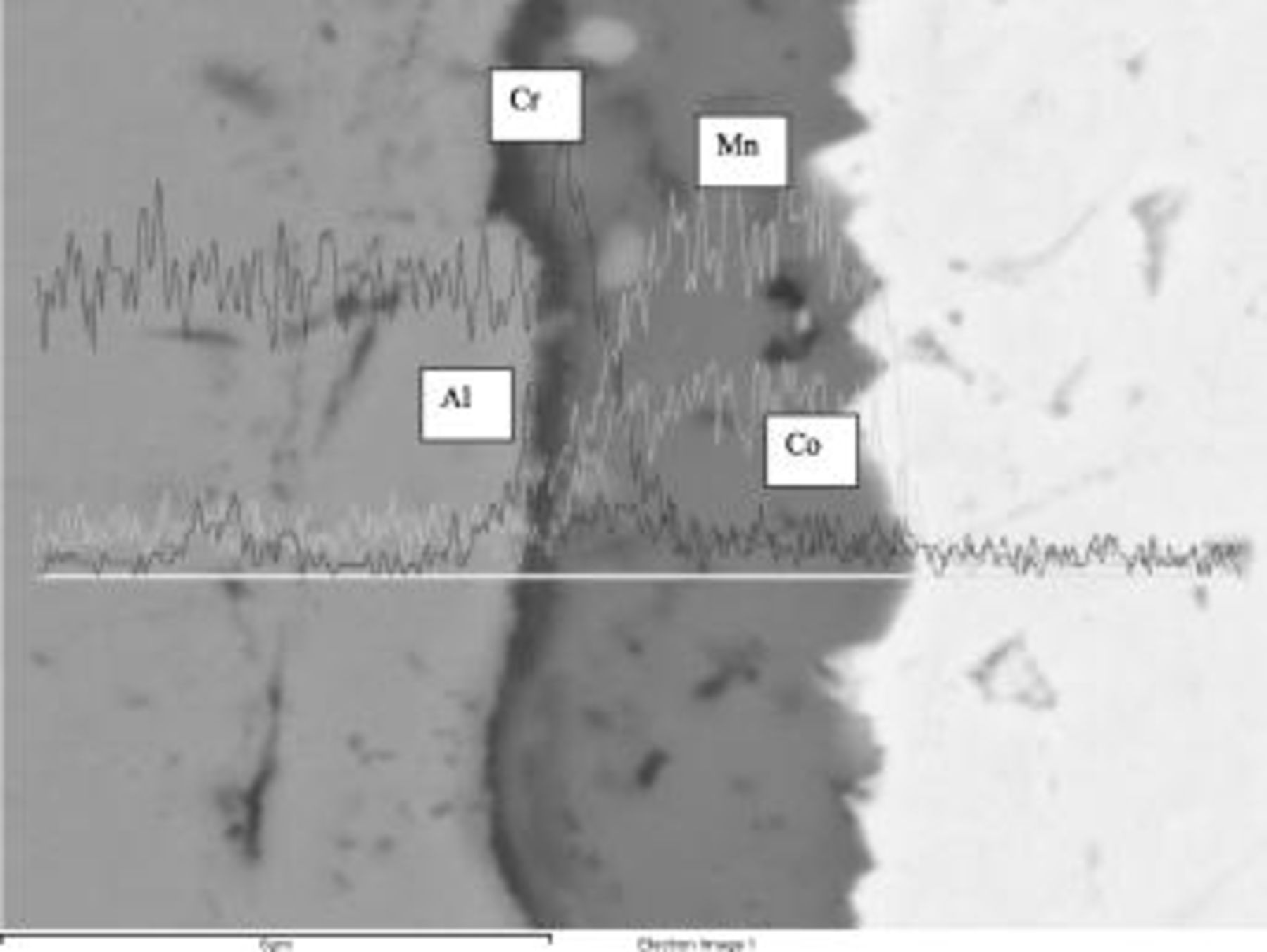
Figure 8. SEM/EDS cross section of dual segment coating after  oxidation in air at 800°C.
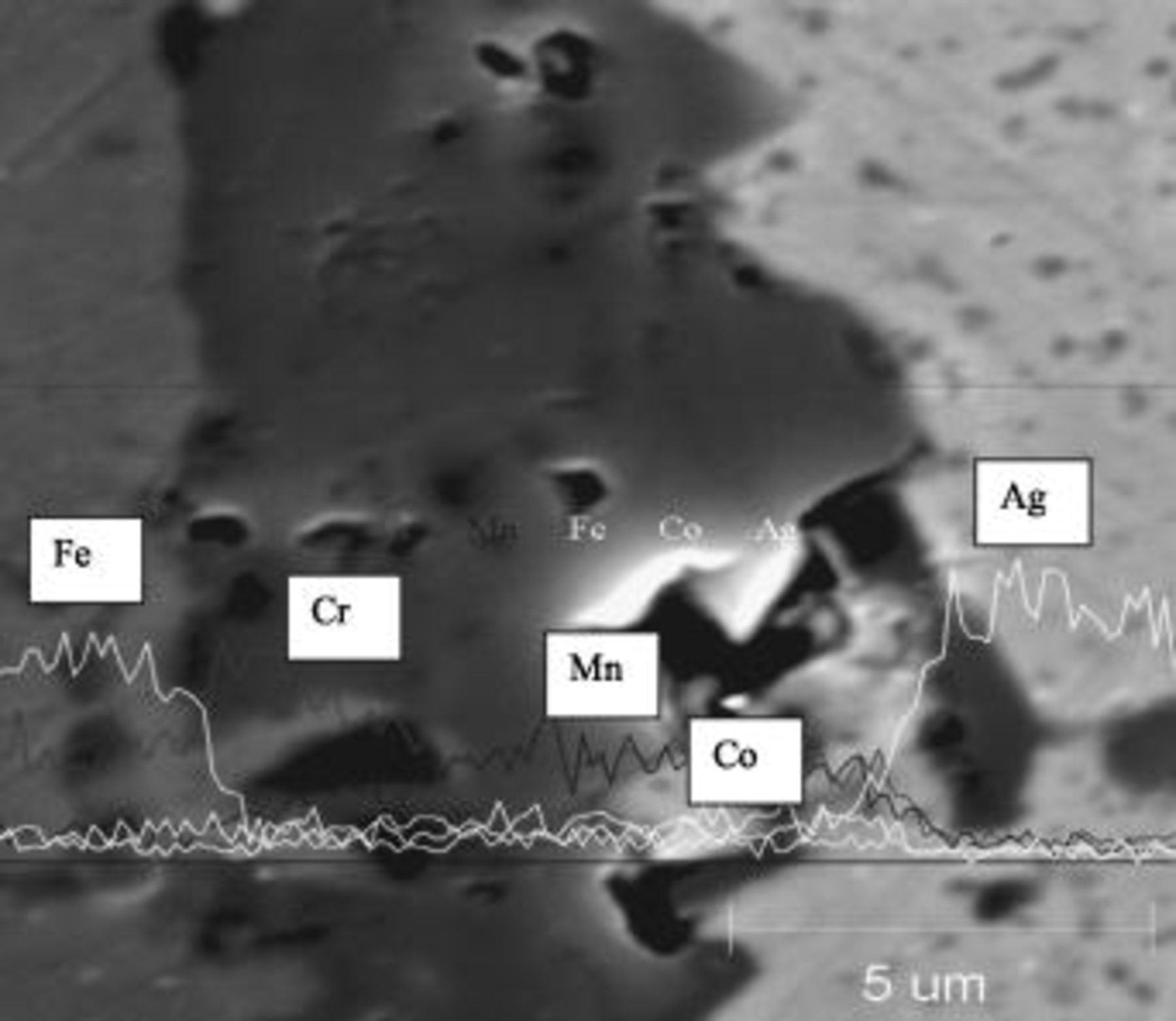
Figure 9. SEM/EDS cross section of dual segment coating after  ASR testing with Ag contact.
Figure 10 displays Cr volatilization results from single upper segment  coated and uncoated Crofer 22 APU (results from the dual segment coating and bond coating alone are currently under evaluation). The single upper segment coated sample shows a 15-fold decrease in Cr volatility. SEM/EDS surface analyses after Cr volatility testing indicate that Cr-rich areas were present on uncoated areas (back side and near edges) of coated sample coupons. Coating damage and resulting Cr exposure is suspected to be caused by the Ni plating process for the uncoated side, as was readily observed in SEM/EDS analyses. Cr diffusion through the Ni plating is also unknown. Two-sided coated coupons are currently under investigation to mitigate these effects; however, these results do indicate a significant inhibition of Cr volatility compared with the uncoated steel.
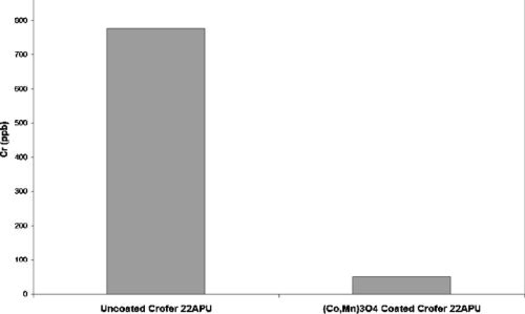
Figure 10. Cr volatility results from  coated and uncoated Crofer 22 APU sample coupons.
Conclusion
Coated and uncoated Crofer 22APU coupons have been investigated as function of exposure to SOFC-cathode gas phase conditions. The continued TGO scale growth observed on the uncoated coupons indicates their long-term incompatibility as SOFC interconnects. Improved long-term ASR stability and decreased Cr volatility of Crofer 22APU has been afforded by the use of two segment filtered arc  in addition to filtered arc assisted EBPVD
  coatings. The observed improvement is likely the result of the diffusion-barrier characteristics of the lower segment coating and the high electrical conductivity and Cr-retention properties of the upper segment coating. Future work will focus on further enhancement of Crofer 22 APU and similar commercial ferritic steels through an extension of the basic coating system presented here.
Acknowledgments
We acknowledge the technical assistance of Norm Williams, Lyman Fellows, and John Getty at Montana State University. Coatings were skillfully prepared by Duane Jones and Oleg Popov. Special thanks to Gerald Meier for fruitful discussion on oxidation kinetics. Portions of this work were supported by DOE under contract no. DE-FC26-04NT42225 and supervised by DOE project officer Travis Shultz. Work at MSU was supported through the High-Temperature Electrochemistry Center (HiTEC), supported by a DOI and DOE subcontract from PNNL, no. 3917(413060-A) .
Arcomac surface Engineering, LLC assisted in meeting the publication costs of this article.