
Abstract
The potentiostatic electrodeposition of platinum was carried out with a nonionic surfactant in the liquid crystalline phase acting as a templating agent. The electrochemically active surface area of  unsupported Pt electrodeposited using a mixture of Brij 56 and n-heptane was increased by a factor of 2.7 compared to Pt deposited without structure-directing additives. The deposit morphology was studied by surface analysis (scanning electron microscopy, atomic force microscopy, and transmission electron microscopy). It was found that with the templating agent, the Pt nanoparticles with a 50 nm diameter had a mesoporous fine structure with pore diameters of 2–3 nm. Oxygen reduction experiments revealed a threefold increase in mass activity, and an improvement of the superficial current density at 0.9 V vs reversible hydrogen electrode (RHE) from
  to
to  due to templating. The intrinsic specific activity of the templated Pt (i.e., current density normalized with respect to the active Pt area) was also improved at potentials more negative than 0.95 V vs RHE. The mesoporous structures studied in this work served as a model for the design of highly active polymer electrolyte membrane fuel cell cathode catalyst layers.
Export citation and abstract BibTeX RIS
The electrochemical reduction of oxygen, as it occurs at the polymer electrolyte membrane (PEM) fuel cell cathode, is one of the most intensively studied aspects of fuel cell technology. This sluggish reaction is considered to be the most limiting factor with respect to the energy conversion efficiency.1 Therefore, in the absence of effective and practical non-Pt catalysts for oxygen electroreduction, the development of improved Pt and Pt alloy catalysts is critical to overcome this technological barrier. The enhanced utilization of the catalytic sites is achieved by designing thin catalyst layers (either as catalyst-coated diffusion layers or catalyst-coated membranes) with low ionic resistance and improved mass transport of oxygen and water.2 Over the past two decades, a decrease in the Pt catalyst loading for  /air PEM fuel cell cathodes from
  (in the case of unsupported Pt) to
  was achieved.3, 4 Gasteiger et al.5 specified a benchmark performance target of
  as a requirement for feasibility, in particular for automotive applications.
The synthesis of core-shell catalysts is an interesting recent development in fuel cell catalysis, especially regarding noble metal cost reduction. The inner part of each catalyst particle consists of a relatively inexpensive metal (e.g., Co, Fe, Mo, and V) while Pt is predominantly present on the particle surface. Srivastava et al.6 carried out voltammetric de-alloying of a Pt–Cu–Co catalyst. In the process, Cu was partially removed, which resulted in a Pt-enriched shell and corresponding surface restructuring. This procedure brought about an approximately twofold increase in the active surface area compared to a standard Pt catalyst (e.g., from 62 to  ). A mass activity of
  was obtained by operating the
  fuel cell at 0.9 V and
  . Saski and co-workers7 synthesized high activity oxygen reduction catalysts by depositing a Pt monolayer on carbon-supported
  nanoparticles. For example, at 0.8 V vs reversible hydrogen electrode (RHE), a mass activity of
  was observed.
The porous structure of the catalyst layer can also have an effect on the performance. The formation of mesoporous hexagonal Pt structures on smooth substrates by electrodeposition aided by nonionic surfactant-based liquid crystalline media is well documented in the literature.8–14 A series of papers by Bartlett and co-workers8–12 showed that the ordered structure of the bulk surfactant matrix is inversely replicated in the precious metal deposit formed on the substrate surface. Aside from the hexagonal phase, isotropic or lamellar phases formed with surfactant/water mixtures can be used for fabricating structured metal deposits.15, 16
Certain nonionic surfactants form hexagonal arrangements of tubular micelles in aqueous media within a certain concentration and temperature domain.8–14, 17, 18 The hexagonal nanostructure of such a liquid crystalline templating electrolyte is a crucial feature for obtaining highly ordered metal deposits. The pore diameter, commonly in the range of 2–15 nm,12 can be adjusted depending on the chain length of the applied surfactant. Hydrocarbons that act as swelling agents can be introduced to enlarge pore diameters. In general, significantly increased surface areas were observed compared to employing a plating bath without structure-directing agents. For example, an active surface area increase of 65% for Pt (deposited onto a gold-coated substrate) was achieved by liquid crystal templating compared to depositing in an aqueous electrolyte without a surfactant.10
The deposition potential is a crucial variable that affects the deposit structure. Elliott et al. reported that at 0.14 V vs standard hydrogen electrode (SHE), a hexagonal porous Pt structure was observed, while a relatively nonuniform deposit resulted from plating at 0.04 V vs SHE ( in both cases). At more negative potentials, completely disordered deposits were formed.10
Most of the work related to liquid crystal templating has focused on electrochemical studies with relatively small electrode sizes. For example, microelectrodes13 or a quartz crystal substrate as utilized in conjunction with an electrochemical microbalance12 were employed as substrates. Concentrated chloroplatinic acid solutions (e.g., 29 wt % of the plating bath, which corresponds to a concentration of 1.9 M in the aqueous phase when combined with 42 wt % surfactant)8, 9 were commonly applied to prepare the catalytic materials. However, low concentrations of platinum are a prerequisite when aiming for economically viable fabrication processes. Further, while the commonly applied surfactant octaethyleneglycol monohexadecyl ether ( ) reliably provides highly structured mesoporous deposits,8 its prohibitively high price of
  makes it unsuitable for mass production of catalyst nanostructures. Guo et al.14 demonstrated that highly ordered mesoporous Pt deposits can be obtained using only
 in conjunction with n-heptane and polyethylene glycol hexadecyl ether (commercial name: Brij 56), which is a relatively inexpensive surfactant
  .
.
This work discusses the application of surfactant-templated platinum catalysts for the oxygen reduction reaction (ORR). Kinetic parameters were determined and compared with those obtained from measurements with a nontemplated catalyst. Further, the templated catalyst was compared with a commercially available Pt black catalyst. All catalysts studied experimentally in this work were applied to the rotating disk electrode (RDE) without carbon support or binder (Nafion or polytetrafluoroethylene).
The long-term stability of electrodes prepared without a binder could be a concern, but during the short-term polarization measurements performed here, the reproducibility of the results was good. By not using a binder, the ohmic drop across the catalyst layer is not a major factor. Hence, resistance effects did not have to be taken into account for the evaluation of the voltammetric data.
Experimental
Electrodeposition
The substrate was a gold RDE ( , Pine Instrument). The electrolyte solutions contained
  either without additives or in conjunction with Brij 56 (
 , with
  , Sigma-Aldrich). In certain cases, 3 wt % n-heptane (Acros Organics) was added to the surfactant solution as a phase-modifying and swelling agent. The same deposition bath composition as employed by Guo et al.14 was used as a basis for comparison, i.e., 42 wt % Brij 56, 0.011 M
  (i.e., 55 wt % of 0.02 M chloroplatinic acid in the aqueous phase), and 3 wt % n-heptane. When Brij 56 was employed, the following sequence of preparation steps was carried out three times to ensure homogeneity of the electrolyte: (i) heating of the templating electrolyte to
  , (ii) vigorous mixing with a glass rod for 10 min, and (iii) cooling to
  .
.
Then, the plating solution was heated to  , and the working electrode was immersed into the solution together with a Pt mesh counter electrode and a saturated calomel reference electrode. The cell temperature was adjusted to
  , and the solution was allowed to stand for 1 h. The electrodeposition was performed at 0.14 V vs RHE using a cathodic charge of either 0.8 or
  , which corresponds to a Pt loading of 0.4 and
  , respectively, according to Faraday's law, assuming 100% current efficiency. After the electrodeposition, the working electrode was soaked in acetone and ultrapure water to remove the surfactant. The Pt surface was cleaned electrochemically by cycling 100 times between 0 and 1.38 V vs RHE in 0.5 M
  at
at  at a scan rate of
  .
.
Preparation of unsupported commercial Pt nanoparticle catalyst
A commercially available Pt black nanoparticle catalyst (Engelhard Inc., fuel cell grade) was suspended in acetic acid followed by sonication for 60 min. The catalyst was then applied to the RDE surface using a micropipette. The desired Pt loading was obtained by a single deposition of  of the Pt nanoparticle in acetic acid suspension followed by air-drying at room temperature. Then, the electrode was cycled as described above.
Surface analysis
High resolution scanning electron microscopy (SEM, Hitachi S-4700) and atomic force microscopy (AFM, Molecular Imaging PicoSPM) in a soft contact mode (tip radius  ) were carried out to compare the deposit morphology obtained without templating additives and with the Brij 56 and n-heptane-based plating mixture. For these studies, Au-coated Si wafers functioned as substrates. Transmission electron microscopy (TEM, Tecnai G2) in a bright field mode was performed to study the effect of heptane addition on the nanoparticle structure, utilizing carbon-coated Au TEM grids (Gilder grids supplied by Canemco Inc.) as substrates. The electroplating conditions were otherwise identical to those used for Pt deposition onto the gold RDE.
Electrochemical testing
The active Pt surface area was estimated based on the underpotential  desorption peaks observed after 100 cycles at a scan rate of
  in 0.5 M
  . A hydrogen desorption charge of
  for the active Pt area was assumed, and the double layer charge was accounted for based on the current density observed at 0.5 V vs RHE during the anodic sweep. The oxygen reduction performance was measured by linear sweep voltammetry in the range of 1.2–0.3 V vs RHE using rotation rates from 1000 to 3000 rpm at
  and a scan rate of
  . A mercury-mercurous sulfate reference electrode (
 ,
,  ) was employed for all electrochemical tests. All current densities were reported as current per geometric electrode area unless specified otherwise.
Results and Discussion
Effects of surfactant presence on the deposit morphology and active Pt surface area
The micrographs in Fig. 1 and 2 show an increase in Pt surface roughness and a significant decrease in particle size due to the presence of Brij 56 and n-heptane during electrodeposition. The smallest particles observed by SEM are in the range of 5–10 nm (see Fig. 2b). Agglomerates with diameters in the range of  to 50 nm are present. The SEM images show that a dense and nonspherical particle growth was obtained without templating, whereas a porous structure consisting of spherical nanoparticles and agglomerates was formed with templating. These structural features are indicative of the spatially constrained nucleation and particle growth due to the surfactant adsorption on the substrate surface.
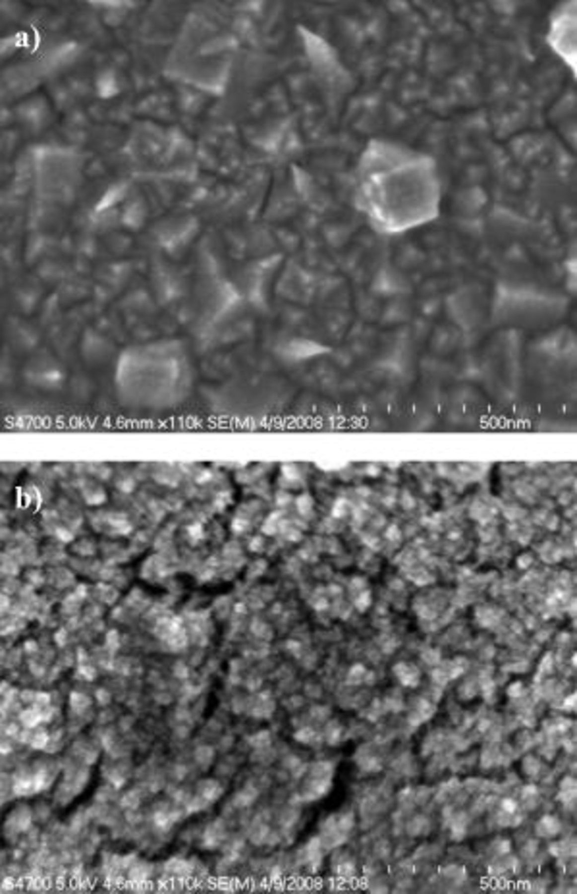
Figure 2. High resolution scanning electron micrographs for Pt deposited at  (a) without additives and (b) with 42 wt % Brij 56 and 3 wt % n-heptane. Pt loading:
  .
.
The TEM micrographs in Fig. 3 reveal that the individual nanoparticles (diameter  to 50 nm) obtained by templating with Brij 56 and heptane possess a mesoporous structure. The pores in the particles obtained with heptane appear to be hexagonally arranged, as indicated by the highlighted area (Fig. 3a), which shows that the hexagonal cylindrical micelle assembly of the bulk-templating solution is replicated in the deposit. Without heptane, the synthesis yielded pores that were located on the particle surface (Fig. 3b), whereas with heptane the pores were a bulk feature of the Pt grains. Further, the pores obtained without heptane were not arranged in a structured manner.
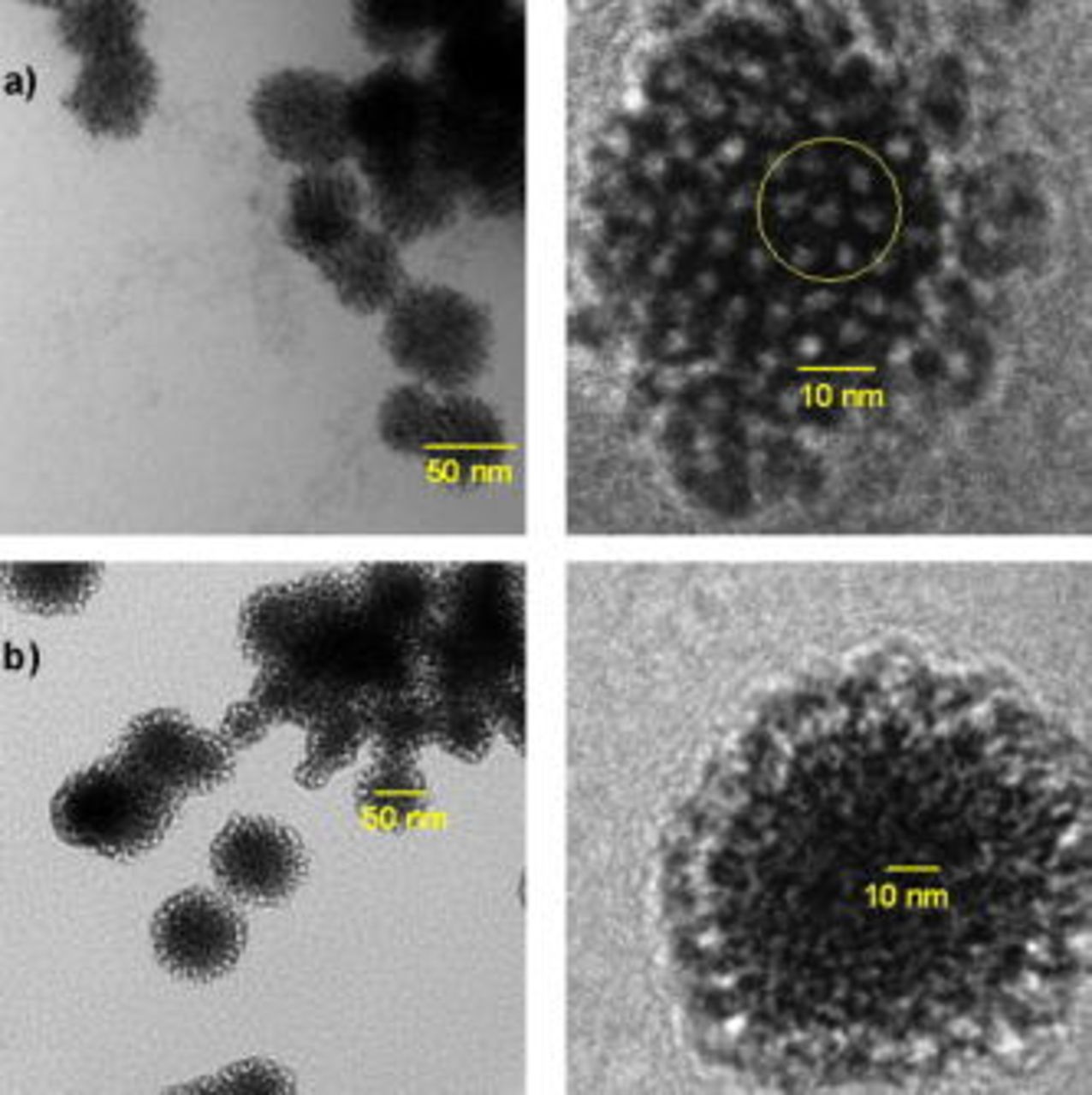
Figure 3. Bright field TEM micrographs for Pt deposited at  using 42 wt % Brij 56 (a) with 3 wt % n-heptane and (b) without n-heptane.
Comparing Fig. 3a and 3b, it can be concluded that without heptane the liquid crystal formation did not take place. Instead, it is assumed that the bulk solution contained micelles of approximately spherical shape present in the isotropic phase.17, 18 The pore diameter was estimated to be  to 3 nm for both deposit types.
Voltammograms in 0.5 M  for Pt electrodeposited onto the Au RDE with and without templating agents are presented in Fig. 4. The current density is reported with respect to the geometric electrode area. The active surface area was increased by a factor of 2.7 from
  without additives to
  with Brij 56 and n-heptane. The respective roughness factors were 40 and
  .
.
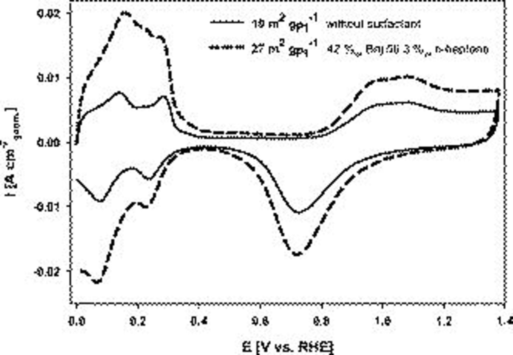
Figure 4. Cyclic voltammograms (100th cycle) of Pt deposited onto a gold RDE with and without templating additives. Conditions: 0.5 M  ,
,  , and
, and  . Pt loading:
  .
.
Oxygen reduction studies and analysis of kinetic parameters
The Pt electrode prepared with Brij 56 and n-heptane templating yielded higher oxygen reduction current densities over the entire potential range compared to depositing without a surfactant, as shown in Fig. 5. At 0.9 V vs RHE, the superficial current density was increased from  to
to  (see Fig. 5 inset). The oxygen mass-transfer limited current densities were
  and
and  for Pt prepared without and with templating agents, respectively. The approximately 12% higher limiting current density for the templated catalyst could be explained by differences in the diffusion layer thickness due to the mesoporous fine structure.
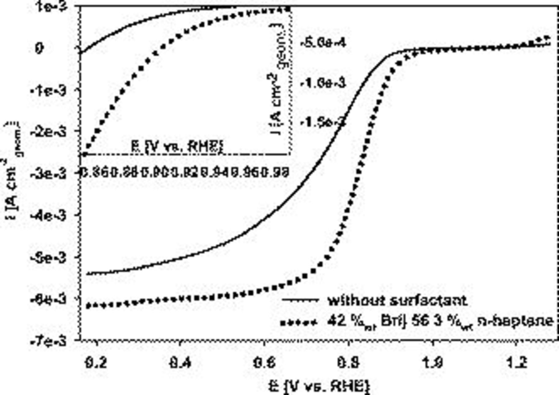
Figure 5. Linear cathodic oxygen reduction sweeps comparing Pt on Au RDE prepared with 42 wt % Brij 56 and 3 wt % n-heptane and without additives. Pt loading:  . Conditions: 0.5 M
  ,
,  ,
,  , and 2500 rpm.
From the measured superficial current density values shown in Fig. 5, the purely kinetic current density  was determined using Eq. 1
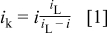
where  is the diffusion-limited current density and
  is the measured current density.19
The kinetic current density was normalized with respect to the real electrochemically active surface area (Fig. 6). The kinetic current density  is also referred to as the (active area) specific catalytic activity. At potentials more negative than 0.95 V vs RHE, the specific activity was improved for the templated catalyst relative to the nontemplated Pt (Fig. 6). This indicates that the templating approach induces profound changes in the intrinsic electrocatalytic activity.
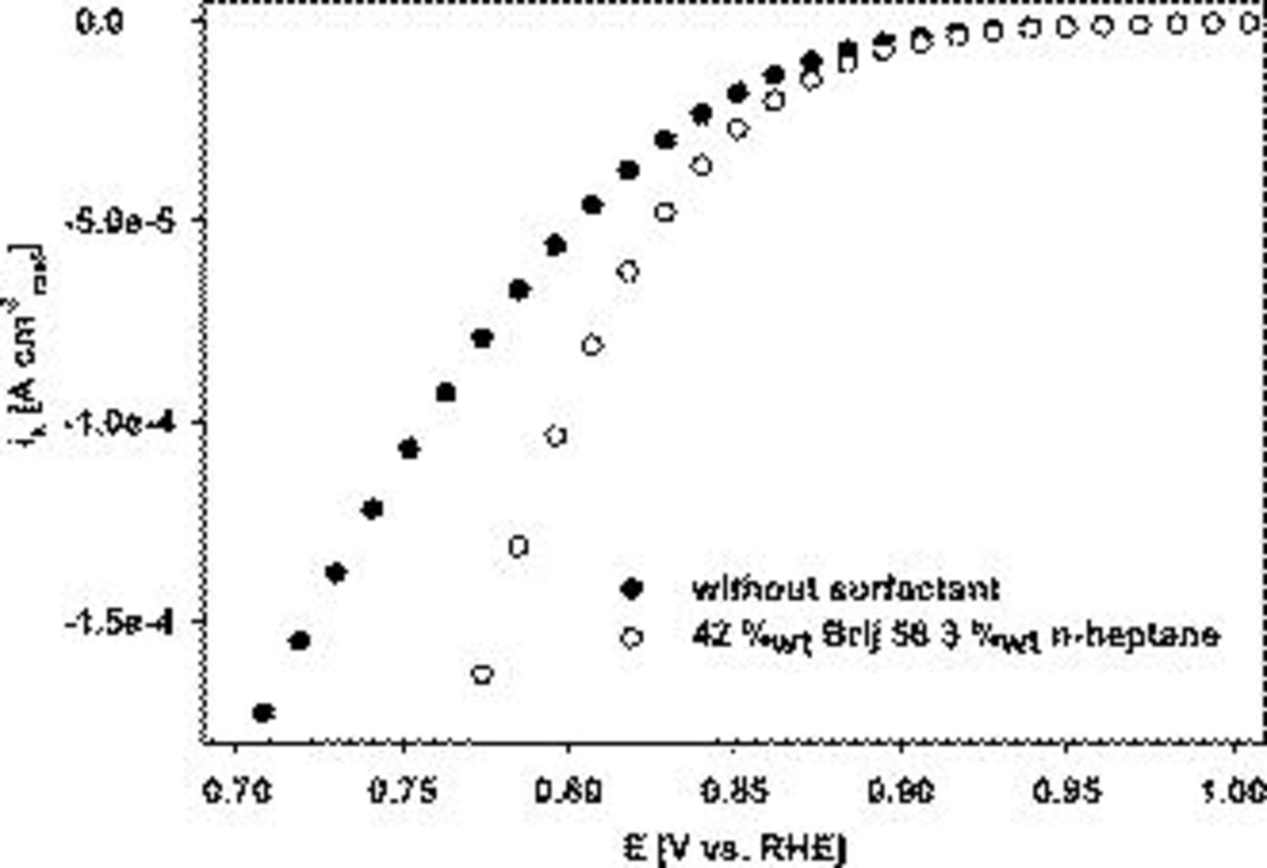
Figure 6. Linear cathodic oxygen reduction sweeps comparing Pt on Au RDE prepared with 42 wt % Brij 56 and 3 wt % n-heptane and without additives. Pt loading:  . Conditions: 0.5 M
  ,
,  ,
,  , and 2500 rpm. Current densities are reported in normalized form with respect to the active Pt catalyst area
  .
.
Without heptane, the active Pt surface area was substantially lower, i.e.,  , compared to
  with heptane (see also Fig. 3 for a comparison of the catalyst morphologies.). Therefore, the oxygen reduction activity was lower for the catalyst synthesized without heptane, as shown in Fig. 7. For example, at 0.9 V vs RHE, the superficial current density was
  without heptane, whereas with heptane, it was
  . In this case, the Pt loading was
  .
.
Figure 7. Linear cathodic oxygen reduction sweeps comparing Pt on Au RDE prepared with and without 3 wt % n-heptane. 42 wt % Brij 56 was present during electrodeposition in both cases. Pt loading:  . Conditions: 0.5 M
  ,
,  ,
,  , and 2500 rpm.
A comparison with published data, obtained under comparable conditions, is presented in Table I. The unsupported Pt catalyst applied without Nafion by Mo and co-workers20 yielded lower performance values compared to the in-house-prepared liquid crystal templated Pt. In terms of mass activity, Shih et. al.21 and Guilminot et al.22 obtained substantially higher values, which can be expected because the respective Pt catalysts were carbon supported. The surface specific activity obtained with the in-house-prepared catalysts is of the same order of magnitude as the values obtained from the literature.
Table I. Comparison of ORR activity at 0.9 V vs RHE and 2500 rpm.
| RDE type | Mass activity
| Specific activity
| Scan rate
|
 (M) (M) |
 
| Reference |
|---|---|---|---|---|---|---|
| Nontemplated Pt/Au | 0.5 | 4.8 | 2 | 0.5 | 25 | This work |
| Templated Pt/Au | 1.5 | 6.6 | 2 | 0.5 | 25 | This work |
| Pt/glassy C | 0.9 | 3.3 | 20 | 0.5 | N/A | 20 |
| Pt/glassy C | 6 | 9.8 | 1 | 1 | 20 | 21 |
| C supported Pt | 17 | 10.6 | 1 | 1 | 20 | 22 |
Tafel plots were generated employing the kinetic current densities for the two types of catalysts, templated (including heptane) and nontemplated, respectively (Fig. 8). In the low current density regime, the Tafel slopes were similar for both catalysts, i.e., 0.082 and  , for catalysts prepared with and without a surfactant, respectively. At high current densities, the catalyst prepared with a surfactant yielded a significantly lower Tafel slope (0.134 vs
  , see also Table II for a summary). Tafel slopes of
  and
and  were reported by several groups for the corresponding low and high current density domains.23–25

Figure 8. Mass-transfer corrected Tafel plots comparing Pt on Au RDE prepared either without structure-directing agents or with 42 wt % Brij 56 and 3 wt % n-heptane. Pt loading:  . Conditions: 0.5 M
  ,
,  , and
, and  .
.
Table II. Tafel analysis for nontemplated and liquid crystal templated Pt.
| Electrodeposition bath composition |
 
|
 
|
|

|
|---|---|---|---|---|
0.01 M 
| 0.175 | 0.090 |

|

|
42 wt % Brij 56, 3 wt % n-heptane,  
| 0.134 | 0.082 |

|

|
The change in the Tafel slope can be attributed to a number of effects, such as a shift in the charge-transfer coefficient,26, 27 different adsorption mechanisms for reaction intermediates,28 a change in surface coverage with oxygen-containing species,29 and structure-induced diffusion effects due to the porous nature of the electrode.30, 31
The exchange current densities were estimated by extrapolation of the low current density regime plot to an overpotential of 0 V vs RHE. The increase in the exchange current density for the templated Pt indicates a higher intrinsic catalytic activity (Table II). Exchange current densities in the range of  to
to  were reported.32, 33 Figure 9 contains linear sweep plots obtained at rotation rates ranging from 1000 to 3000 rpm for a Pt catalyst prepared with Brij 56 and n-heptane. The inset in Fig. 7 shows the linear dependence of the diffusion-limited current density (measured at 0.18 V vs RHE) on the square root of the rotation rate. Based on Eq. 2, the theoretical value of four electrons transferred during the reduction of one oxygen molecule was confirmed, assuming
  ,
,  , and
, and  . 34, 35

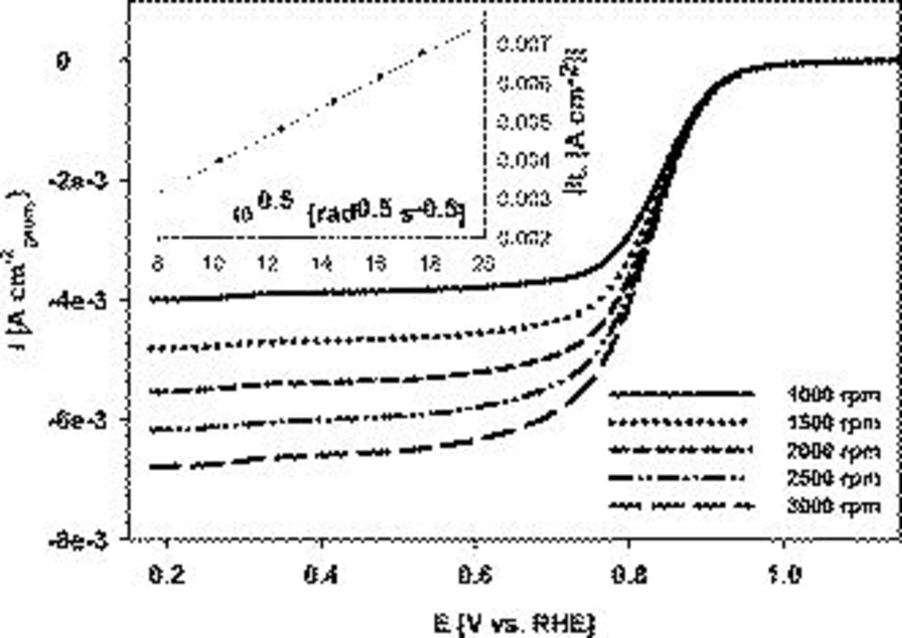
Figure 9. Linear cathodic oxygen reduction sweeps for Pt on Au RDE prepared with 42 wt % Brij 56 and 3 wt % n-heptane. The inset shows the correlation between the mass-transfer limited current density and the square root of the rotation rate. Pt loading:  . Conditions: 0.5 M
  ,
,  , and
, and  .
.
Effect of catalyst loading and comparison with commercial unsupported Pt black
The oxygen reduction activity of the in-house-prepared liquid crystal-templated Pt catalyst and commercially available Pt black nanoparticle catalyst was compared by linear sweep voltammetry. The selected loadings were 0.2 and  . In each case, the active surface area was
  , both for the commercial and the in-house-prepared catalysts. Figure 10 shows that with a loading of
  , the current densities were identical for the two catalysts. With a loading of
  , the commercial Pt black marginally outperformed the liquid crystal-templated catalyst at
  vs RHE. Differences in crystallographic features between the commercial and the templated catalyst could play a more significant role at low Pt loading. This aspect has to be further investigated.
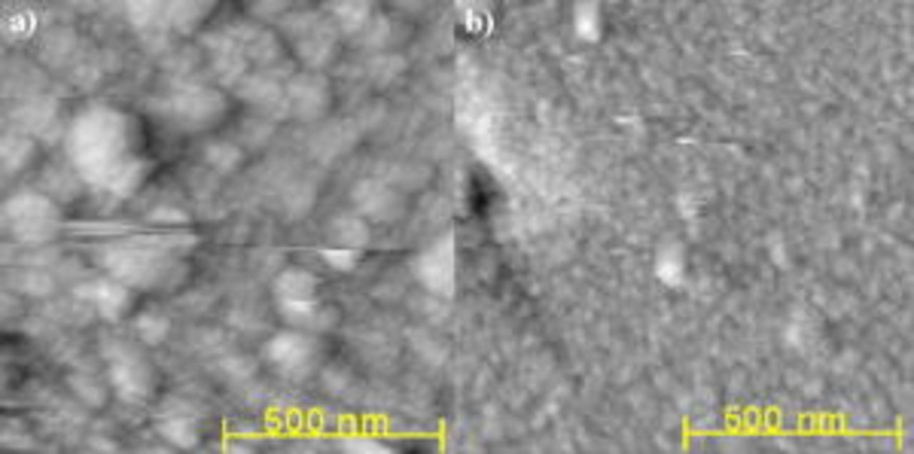
Figure 1. AFM micrographs for Pt deposited at  (a) without additives and (b) with 42 wt % Brij 56 and 3 wt % n-heptane. Pt loading:
  .
.
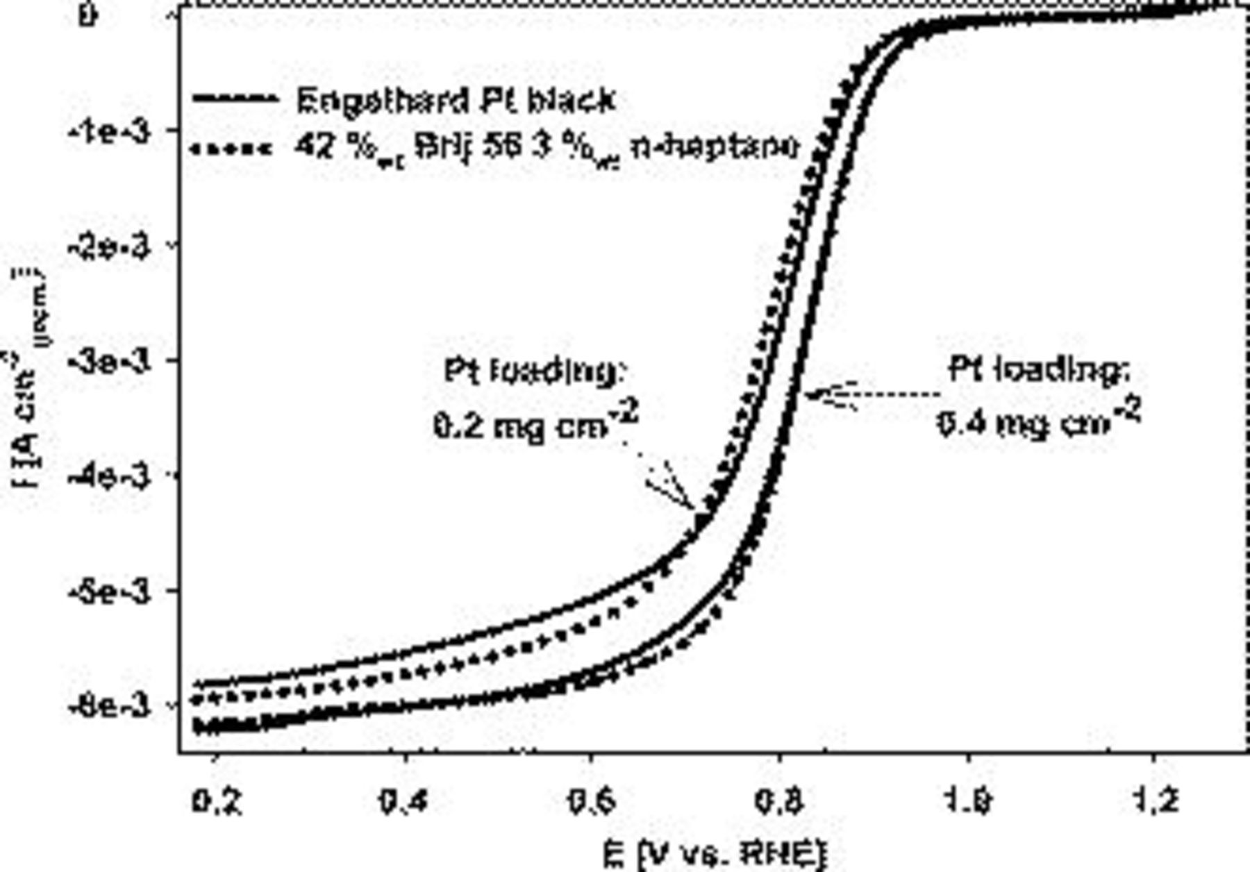
Figure 10. Oxygen reduction performance of Pt on Au RDE prepared with 42 wt % Brij 56 and 3 wt % n-heptane compared with unsupported Pt black nanoparticle catalyst (Engelhard Inc.). Conditions: 0.5 M  ,
,  , 2500 rpm, and
  .
.
To verify the reproducibility, both the commercial and the liquid crystal-templated catalyst were prepared three times, using a loading of  , and tested voltametrically at a rotation rate of 2500 rpm. Table III indicates a good degree of reproducibility for the kinetic current density at 0.9 V vs RHE and the mass-transfer limited current density (measured at 0.18 V vs RHE). The application of the templating procedure for incorporating the catalyst into a gas-diffusion electrode or channel constrained metallization configuration may be advantageous compared to applying an unsupported nanoparticle catalyst using a conventional method, such as brushing or spraying. Using a traditional method can imply a decrease in the active catalyst area due to agglomeration, whereas the presence of a templating agent would ensure an adequate catalyst dispersion and therefore improved activity. Current research efforts in our group are directed toward implementing templated Pt for cathode-catalyst-coated membranes.
Table III. Repeat runs for freshly prepared Pt catalysts (loading:  ).
).
| Engelhard Pt black | Brij 56 with n-heptane templated Pt | |||
|---|---|---|---|---|
 (0.9 V vs RHE) (0.9 V vs RHE) |

|
 (0.9 V vs RHE) (0.9 V vs RHE) |

| |
| Replicate no. |

|
| ||
| 1 | 6.9 | 62.2 | 7.2 | 61.6 |
| 2 | 7.1 | 60.4 | 7.2 | 58.2 |
| 3 | 7.2 | 60.0 | 7.9 | 60.3 |
Conclusions
The liquid crystal assisted potentiostatic deposition of platinum yielded particles with diameters of about 50 nm and a mesoporous fine structure that reproduced the bulk templating pattern formed by the hexagonal micellar phase. RDE experiments indicated that the oxygen reduction performance was improved at potentials more negative than 0.95 V vs RHE for the templated catalyst compared to Pt prepared without structure-forming additives. This improvement was partially due to the  times larger active Pt surface area and was also a result of the improved intrinsic activity, as indicated by the exchange current density and the surface specific activity. TEM analysis revealed that the addition of heptane to the surfactant bath is necessary to obtain a liquid crystalline electrolyte under the conditions studied in this work. The liquid crystal-templated mesoporous Pt catalyst showed comparable performance relative to a commercially available unsupported Pt black nanoparticle catalyst. In terms of fuel cell electrode structures, the templated catalyst is considered advantageous compared to unsupported Pt black due to improved control of the catalyst dispersion and therefore an expected enhancement of activity. The unsupported mesoporous catalyst may provide improved long-term stability compared to the carbon-supported Pt during fuel cell operation because the carbon corrosion issue would be eliminated. Further, the direct deposition of Pt onto a proton exchange membrane may lead to a more stable catalyst attachment to the membrane. A thinner carbon-free catalyst layer would also have a relatively low resistance and shorter mass-transport pathways, thus improving the overall fuel cell performance. In general, mesoporous Pt structures, as obtained by this study, can be utilized for diverse applications, such as electrochemical sensors,23 dye-sensitized solar cells,24 or fuel cell catalysts.13
Future work is aimed at implementing the templating technique for electroless (i.e., nonfaradaic) deposition of Pt directly on the membrane. Thus, the present study on templated electrodeposition serves as a model for assessing the structure-directing capability of the surfactant system and the related electrocatalytic oxygen reduction activity of the generated Pt structures.
Acknowledgments
The authors acknowledge the support from the Natural Sciences and Engineering Research Council of Canada, Ballard Power Systems, and helpful discussions with Shanna Knights and Stephen Campbell.
The University of British Columbia assisted in meeting the publication costs of this article.
List of Symbols

| Tafel slope for high current density regime, 
|

| Tafel slope for low current density regime, 
|

| bulk oxygen concentration, 
|

| diffusion coefficient for oxygen in 0.5 M  , , 
|

| Faraday constant: 
|

| current density with respect to geometric electrode area, 
|

| exchange current density, 
|

| mass-transport corrected (kinetic) current density, 
|

| mass-transport limited current density, 
|

| number of electrons |

| temperature, 
|
Greek
| η | overpotential, V |
| ν | kinematic viscosity, 
|
| ω | rotation rate, 
|