Abstract
Room temperature ionic liquids (RTILs) with the bis(fluorosulfonyl)imide (FSI) anion exhibit higher conductivities than the corresponding bis(trifluoromethanesulfonyl)imide (TFSI) compounds, thereby generating interest as novel electrolytes for lithium batteries. The electrochemical properties of a series of FSI RTILs, at inert metal and lithium electrodes, have been investigated using cyclic voltammetry (CV) and electrochemical impedance spectroscopy. Addition of  ,
,  , or LiTFSI extends cathodic limits to significantly more negative values and allows reversible lithium electrodeposition. Variable-current cycling of symmetrical
  coin cells reveals significant changes in electrode–electrolyte interphasial impedance, which depends on the identity of the lithium salt anion, the concentration of the salt, and the RTIL cation. For most cells, voltage–time curves become unsteady early in duty, which is consistent with the formation of dendrites on the lithium surface. A stable voltage behavior returns within around 20 cycles, at notably a lower current density presumably because detachment/reattachment of dendrites eventually re-establishes a contiguous lithium electrode with a higher surface area. Importantly, the combination of the kinetics of lithium deposition and morphology of the deposit in FSI anion-based RTIL media does not result in lithium penetration of the separator. Therefore, FSI-based electrolytes can play a key role in the development of a viable lithium-metal battery technology.
Export citation and abstract BibTeX RIS
Increasing consumer demand for power and energy density is driving the development of the next generation of lithium-ion batteries.1 To date, however, these developments have been incremental, with the active materials employed in today's batteries being little different from those in Sony's first release back in 1991. It can be argued that this lack of progress is largely due to a failure to develop improved electrolytes. New "high voltage" cathode materials have been described regularly over the years; yet any benefits are seldom realized due to the limited electrochemical stability of organic carbonate-based electrolytes.2 These systems are also compromised by poor thermal stability, appreciable volatility (and flammability), and significant toxicity.
Certain members of the vast family of compounds known as room temperature ionic liquids (RTILs) have properties that address many of the concerns with classic organic electrolytes.3 Holzapfel et al. were one of the first groups to report sustained cycling of a lithium-ion battery with an ionic-liquid electrolyte medium.4 They used 1-ethyl-3-methyl-imidazolium bis(trifluoromethanesulfonyl)imide  and LiTFSI doped with vinylidene carbonate (VC) in an effort to form a stable solid electrolyte interphase (SEI) at the graphite anode.4 While these cells displayed a reasonably constant discharge capacity, VC is progressively consumed during long-term charge–discharge cycling,5 with the result that intercalation of the imidazolium cation into the graphite proceeds unchecked and eventually causes total destruction of the anode.6
While TFSI ILs are problematic at graphite electrodes, they behave well at metal electrodes, including lithium. This seems to be due to a stabilization that occurs under reducing conditions when both lithium ions and TFSI are present. The effect is a pronounced negative shift  of the reduction limit, as defined by the onset of bulk reduction of the electrolyte, which then allows full access to the electrochemical reduction of lithium. This is shown by Katayama et al.7 (in
  ) and by Matsumoto et al.8 (in
  LiTFSI or
  ). Both groups postulated that the stabilization was due to the formation of a protective SEI layer, in which the incorporation of lithium ions is essential to maintaining conductivity. Details of the properties of the TFSI-based SEI on lithium and the mechanism of formation have been described by Howlett et al. , who employed a combination of electrochemical and surface analytical (X-ray photoelectron spectroscopy) techniques.9, 10 However, despite the improved behavior with a metallic lithium anode, complete lithium-ion cells (with
  cathodes) exhibit significant capacity fading, which appears to be due to degradation of the cathode.11
As an alternative to TFSI, several groups are now investigating the bis(fluorosulfonyl)imide (FSI) anion, which is a simple analog of the TFSI anion (Fig. 1). First described in 1962,12 Michot et al. patented its use as a plasticizing anion in solid polymer electrolytes.13 More recently, Matsumoto et al.14 and Zhou et al.15 showed that selected pyrrolidinium and imidazolium FSI ILs have increased conductivity and lower viscosity when compared with the corresponding TFSI-based compounds. Further, with the addition of a lithium salt (LiTFSI or  ), highly reversible deposition-stripping of lithium can be undertaken at graphite electrodes.16–18 At a platinum electrode, mixtures of
  and LiTFSI not only display reversible lithium electrochemistry,14 but the behavior is also characterized by a shift of
  in the cathodic reduction limit for the electrolyte.19 This is consistent with the behavior expected when both
  and
and  ions are present (see above).
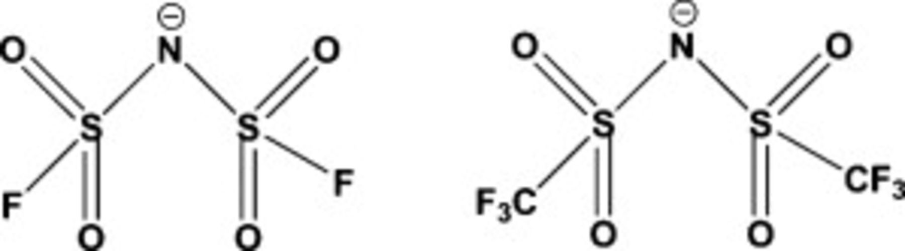
Figure 1. Chemical structures of the FSI anion (left) and the TFSI (right).
A successful use of FSI-based ILs is not conditional on the presence of TFSI. Sugimoto et al. , employing mixtures of  and
and  and adding
  , demonstrated that the intercalation of lithium at graphite electrodes is somewhat reversible at a
  mole ratio of 1.0:0.27 but rapidly becomes poorly defined if the fraction of FSI is reduced further.17 Appetecchi et al. included mixtures of
  and
and  in their recent investigation of members of the pyrrolidinium-TFSI-FSI-
 system.20 Although cyclic voltammograms were not reported, a mixture of
  and 0.3 M
  seemed to support a well-defined reduction of lithium at a platinum electrode. Ionic-liquid (IL) electrolytes with only the FSI anion present have received relatively little attention. Zaghib et al. , who were the first to introduce LiFSI as an electrolyte in an organic salt–solvent system,21 showed that both
  and
and  (with 0.7 M LiFSI) support steady charge–discharge cycling (with good discharge capacity and charging efficiency) of coin cells with
  cathodes and graphite anodes.22 The behavior of mixtures of
  and LiFSI (0.2 and
  ), at a range of electrode materials, has been investigated by Bhatt et al.23 At the higher concentration of lithium salt, highly reversible lithium electrochemistry is observed at nickel, platinum, and lithium electrodes. At the latter, repetitive cycling generates values of electrode (SEI) impedance as low as
  .23
.23
While a limited number of studies suggest that an all-FSI IL electrolyte can produce excellent performance, at carbon and metal electrodes, most research to date has focused on mixtures that include both TFSI and FSI. This may simply reflect the established acceptance of TFSI ILs as good replacement electrolytes in many electrochemical systems. However, there is also evidence that links the SEI that forms when TFSI is present with a range of electrode-protecting properties;8–10 no such evidence is available when FSI completely replaces TFSI. The purpose of this study is to conduct an in-depth electrochemical investigation of a series of FSI-based ILs in which the composition of the electrolyte (concentration of lithium, identity of lithium salt, etc.) is optimized for use in lithium batteries. This paper looks specifically at the effect of mixed anions on the SEI by CV, impedance spectroscopy, and symmetrical cell cycling.
Experimental
A range of ILs was purchased from Dai-ichi- Kogyo Seiyaku Co. Ltd., Japan, including 1-propyl-1-methyl-piperdinium FSI ( , Elexcel IL-130), 1-propyl-1-methyl-pyrrolidinium FSI (
 , Elexcel IL-120), and 1-ethyl-3-methyl-imidazolium FSI (
 , Elexcel IL-110). Many ILs were also prepared in our laboratories, including 1-butyl-2,3-dimethyl-imidazolium FSI (
 ) and trihexyldodecylphosphonium FSI (
 ) synthesized via metathesis reactions of the corresponding halide salts. All the ILs were dried over lithium metal and moisture contents determined using the Karl Fischer method:
  , 20 ppm;
  , 20 ppm;
  , 20 ppm;
  , 20 ppm; and
  , 10 ppm.
Lithium bis(trifluoromethanesulfonyl)imide (LiTFSI, 3 M) and lithium tetrafluoroborate ( , Stella Corporation) were dried at
  under vacuum for 48 h. Lithium hexafluorophosphate (
 , Aldrich) was dried at
  for 1 week under vacuum. Electrolyte solutions were made in concentrations of 0.2, 0.5, and
  using the dried lithium salts.
Electrochemical measurements were recorded using a μ-AutoLabIII potentiostat (Ecochemie, The Netherlands). CV measurements were obtained in a conventional three-electrode cell comprising either a Pt microelectrode  or glassy carbon (GC) disk
  working electrodes and large surface area Pt counter electrodes. For the reference electrode, a
  electrode is described elsewhere.24
Coin cells were used to determine the symmetrical cycling and impedance properties of the electrolyte. A CR2032 stainless steel cell was used with 10 mm Li disks, and 13 mm Whatman Glass Fiber GA separator disks.  of IL electrolyte was used to ensure a complete wetting of the separator. Impedance spectroscopy was undertaken on a Solartron 1600 frequency response analyzer between 1 MHz and 10 mHz. Symmetrical cell cycling was conducted on a Maccor Series 4000 battery test station at both room temperature and
  .
.
Results and Discussion
Potential windows of FSI-based ILs
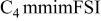
The potential windows of the FSI-based ILs have been measured using CV at GC and platinum (Pt) working electrodes. The results obtained are summarized in Table I, and typical voltammograms are shown in Fig. 2A. The cathodic and anodic limits were extracted from the first derivative of the cyclic voltammogram where a current cutoff of  was used to define the potential limits. Overall, the magnitude of the electrochemical window, for several of the ILs, compares well with data reported by Matsumoto et al.14 In the oxidative stability of the pure ILs, trends are observed as the cation is changed. First, the ILs with imidazolium cations all have potential limits ca. 0.5 V lower than those based on the saturated cations (pyrrolidinium and piperidinium). The lowest oxidation stability observed was for the phosphonium,
  IL. While several studies have examined the roles of cation and anion in the setting of the oxidative potential limit of imidazolium ILs,25–27 none of these studies have been able to make unequivocal assignments to these roles. Presumably, this is due to the complexity of the reactions that take place, which is amplified by the likelihood of cation oxidation products reacting with IL anion and vice versa.
Table I. Electrochemical windows of FSI anion-based ILs at GC and Pt working electrodes. Also shown, the cathodic limit obtained when  salts are dissolved into solution. All measurements were recorded at
  in an Ar dry box.
| RTIL |

|

| 0.2 mol  LiTFSI LiTFSI | 0.5 mol  LiTFSI LiTFSI | 1.0 mol  LiTFSI LiTFSI | 0.2 mol   | 0.5 mol   | 1.0 mol   | 0.2 mol  
| 0.5 mol  
|
|---|---|---|---|---|---|---|---|---|---|---|

| −2.30 to 2.30 | −2.60 to 1.65 | −3.30 | −4.0 |
| −3.40 | −3.95 | −3.95 | −3.30 | −3.85 |
| −2.70 to 1.75 | −2.80 to 1.45 | −4.00 | −3.90 | −4.00 | −4.10 | −4.50 | −4.20 | −4.15 | −4.10 |

| −2.75 to 1.70 | −2.60 to 1.60 | −4.00 | −3.70 | −3.70 | −4.00 | −3.80 | −3.70 | — | — |

| −2.80 to 2.70 | −3.65 to 2.20 | −4.50 | −4.50 | −4.00 | −4.20 | −4.00 | −4.10 | −4.50 | −4.50 |

| −3.35 to 1.90 | −3.50 to 2.10 | −3.80 | −4.50 | −4.20 | −3.80 | −3.85 | −4.10 | −3.85 | −3.80 |

| — | −3.60 to 1.30 | — | — | −4.2 | — | — | — | −4.30 | −4.30 |

| −2.80 to 2.60 | −1.80 to 2.00 | −4.40 | −4.40 |
| −4.20 |
|
| −4.40 |
|
aAll potentials quoted vs the  reference electrode.24
bOnly the cathodic limit reported. cData not reported as a consequence of Li reduction peak broadening into IL reduction process. dData reported for
reference electrode.24
bOnly the cathodic limit reported. cData not reported as a consequence of Li reduction peak broadening into IL reduction process. dData reported for  solutions due to solubility limits. eLi salt does not fully dissolve.
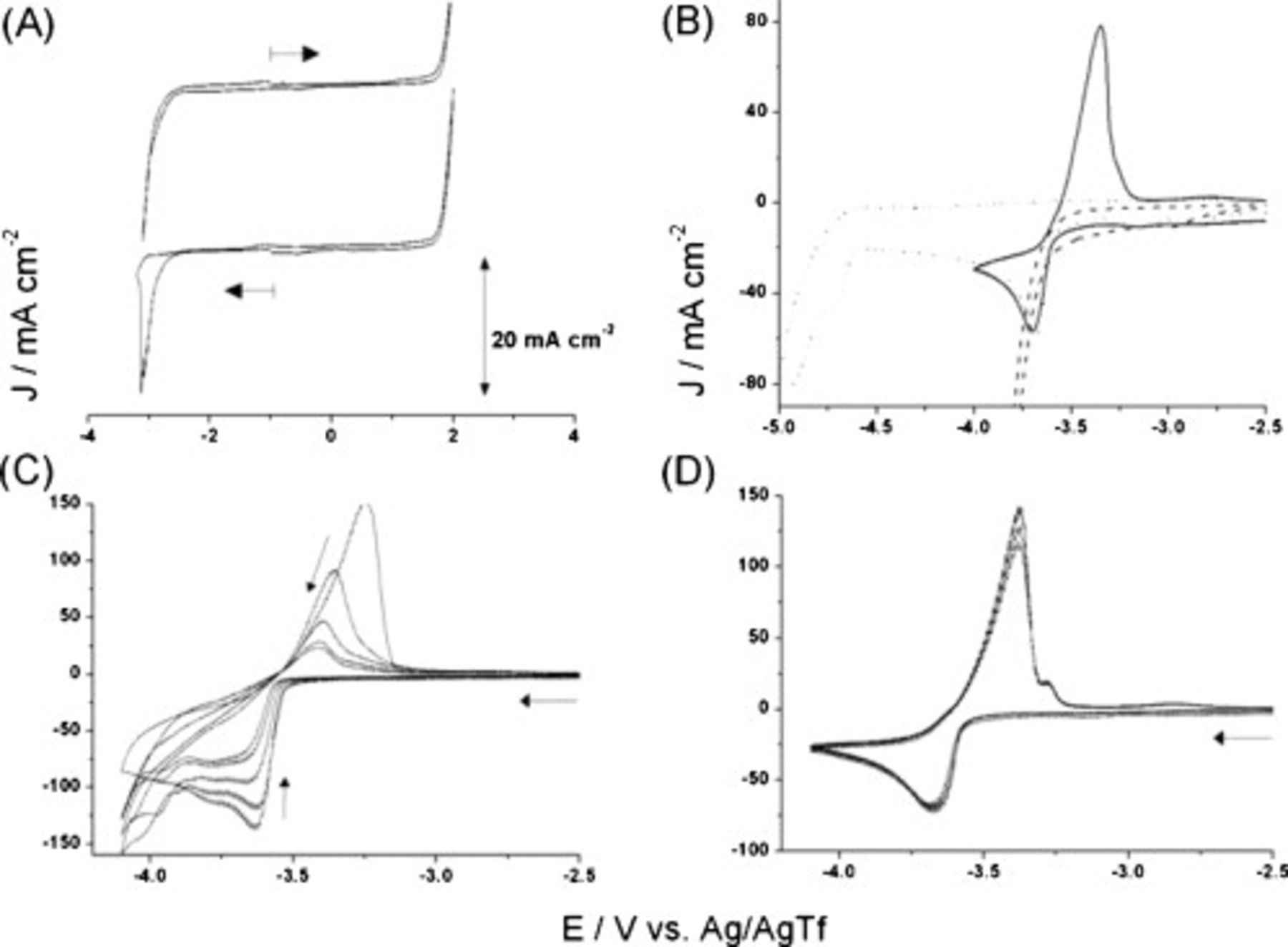
Figure 2. Cyclic voltammograms (Pt working electrode,  , room temperature) for FSI-based ILs: (A) neat
  (arrow indicates initial scan direction, starting at −1 V); (B) neat
  (---) and
  (—), showing the effect of switching the potential where IL breakdown occurs (...); (C)
  ; (D)
; (D)  .
.
The reductive stability of the FSI ILs at a Pt electrode follows the order of  (Table I). The reductive stability changes at a GC electrode with the following order observed:
  . Most likely, the differences are due to changes in the kinetics of the reduction reactions that take place. Such changes may be important when comparing the performance of IL electrolytes in lithium-ion cells with graphite electrodes against those with lithium electrodes.
The inferior reductive limit of the imidazolium cation-based ILs is attributed to the availability of a known one-electron reduction process, which involves the carbon atom at the 2-position of the cation ring. Ultimately, this leads to the formation of the corresponding carbene via the mechanism determined by Gorodetsky et al.28 This assertion is supported by the increased reductive stability of the trisubstituted cation,  , for which the reduction potential is approximately 200 mV more negative than that of
  , with the same anion (Table I).
Electrochemical behavior of mixtures of Li salts and FSI-based ILs
It has been previously reported that mixtures of LiTFSI and  exhibit a higher cathodic stability when compared to neat
  .14, 19 Those studies suggested that LiTFSI-doped
  , which has improved physical properties over a
  electrolyte, could be used as a battery electrolyte. To test whether this finding was more broadly applicable to other FSI-based ILs, we studied the electrochemical behavior of many other FSI ILs in the presence and absence of LiTFSI and several other lithium salts.
Typical cyclic voltammograms recorded for  , neat and then doped with
  LiTFSI, are shown in Fig. 2B. In the absence of added LiTFSI, the IL reduction processes begin at around −3.50 V. With the lithium salt added, the reduction of
  (and deposition of lithium metal) is clearly observed at a peak potential of −3.70 V vs
  with the associated stripping/dissolution process at −3.35 V. If the reductive scan is continued further negatively, the bulk reduction of the IL is ultimately reached at extremely negative potentials, beginning at ca. −4.60 V. Thus, addition of LiTFSI to the IL clearly increases significantly the cathodic limits of the FSI-based IL.14, 19 Similar results are obtained for
  with LiTFSI where, in the absence of LiTFSI, the reductive limit at a Pt electrode is −2.3 V, while in the presence of LiTFSI, the limit is increased to between −4.0 to −4.5 V depending on the salt concentration.
As can be seen from the data in Table I, all of the ILs investigated with added LiTFSI exhibited an increase in reductive limit compared with the neat IL. However, if the voltammetric scan is allowed to proceed into the potential region where significant IL breakdown occurs, then the oxidation of Li (stripping the metal from the electrode surface) is greatly diminished, which indicates that passivation of the electrode surface has occurred. For  (
( LiTFSI), Fig. 2B shows that this passivation is essentially complete, with no detectable current for oxidation of lithium. Similar results were obtained for
  , in line with published data.19 For imidazolium-based cations, with LiTFSI added, reversible voltammetric responses for lithium could also be obtained, as also observed by Matsumoto et al. at a GC electrode.14
So far, clearly, the introduction of lithium ions (at  of LiTFSI) leads to an increase in the stability of the IL electrolytes to reduction and that this stabilization is moderated to a degree by the choice of cation. A question that remains, however, is whether the stabilization is: (i) simply due to the presence of lithium ions or (ii) is a more complex function of solution composition, involving the anion that accompanies the lithium ion (e.g., TFSI in Fig. 2). Both
  and
and  are readily soluble in most of the FSI ILs investigated in this study, and the cathodic limits obtained are summarized in Table I. The salts lithium bis(oxalatoborate) and lithium triflate were not sufficiently soluble for investigation.
A comparison of the reductive limits for  -,
-,  -, and
  -doped mixtures shows that cathodic stabilization occurs in all cases, with the degree of stabilization (i.e., shift in reductive limit compared with the neat IL) of up to 1 V, depending on the IL (Table I). Importantly, all three lithium salts exert approximately similar stabilization effects, and in each case the deposition and stripping of lithium retain a high degree of reversibility. Multiple-scan cyclic voltammograms for
  (0.5 m
  ) and
) and  (0.5 m
  ) are shown in Fig. 2C and 2D. The former, though clearly affected by resistive distortion (presumably associated with the SEI), is still chemically reversible and is able to support reliable
  cycling (see below). The latter, which combines the greater cathodic stability of the pyrrolidinium cation with tetrafluoroborate, provides a remarkably stable current density through several potential cycles. Compared with the other anions examined, this combination exhibits the least susceptibility to passivation (as described above).
Sugimoto et al. , looking at the behavior of  salt mixtures at graphite electrodes, also showed that TFSI can be replaced by tetrafluoroborate but that the maximum concentration of the second ion must be considerably lower in
  than in TFSI to avoid significant degradation in the reversibility of lithium intercalation–deintercalation.17 As implied, the behavior of a system with only the FSI anion present is excellent at carbon and metal electrodes.23, 29
In this study, all three lithium salts (TFSI,  , and
, and  ), when mixed with a variety of FSI ILs, perform well at platinum electrodes and at the concentrations that are required for use as lithium battery electrolytes. The key phenomenon that establishes this behavior is a cathodic stabilization whereby the limit of reduction for the bulk electrolyte is shifted to significantly more negative potentials. All evidence at this stage indicates that achieving this stabilization requires the presence of a minimum fraction of either the FSI or TFSI anion in the electrolyte. This then ensures that deposited lithium metal on the electrode surface develops an SEI with the properties that protect the electrode during subsequent stripping–deposition cycles. There are, however, major influences from both the IL cation, particularly apparent with the imidazolium species, and from the anions present in the IL (from the IL and Li salt used). The effect of IL cations on the performance of IL-based electrolytes was examined by the impedance characteristics of a series of Li–Li symmetrical cells, and further details are presented below.
Effect of temperature on FSI IL potential windows and Li deposition
The effect of temperature on the potential windows has been studied for  and
and  , and the results are shown in Fig. 3A. It is evident that as the temperature increases a contraction of the potential windows occurs. In
  , a contraction of up to 1 V is observed as the temperature is increased from 25 to
  . Similar contractions are also obtained for
  where up to 1.2 V is observed depending on the electrode material. These contractions in the potential window are most likely due to the effect of increased temperature on the kinetics of the redox processes, and subsequent chemical reactions, that effectively define the potential limits in a voltammetric scan. Recently, Lockett et al. also reported that the potential windows of
  ILs (where
  , 4, and 6) decrease as a function of increasing temperature.30
Figure 3. (A) Effect of increasing temperature on the potential window,  , of
, of  (☆),
(☆),  (○), GC (solid symbols), or Pt (empty symbols) working electrodes recorded at
  scan rate. (B) Cyclic voltammogram of
  LiTFSI
  at a Pt working electrode at room temperature (—) and at
  (...) recorded at
  scan rate vs Pt wire quasi-reference electrode.
The effects of temperature on the characteristics of lithium deposition/stripping were also investigated, as illustrated by the responses for  doped with
  LiTFSI (Fig. 3B). The cyclic voltammograms recorded as a function of temperature show that as the temperature is increased and the potential window contracts, the
  deposition process begins to coincide with the reductive limit of the electrolyte. At ca.
  , the breakdown of the IL at the cathodic limit overshadows Li deposition, and significant IL decomposition is observed (as determined from similar experiments in the absence of any Li salt). When switching the potential scan in regions where IL breakdown occurs, significantly diminished peak currents due to lithium stripping are observed. This effect is clearly seen in Fig. 3B. Presumably, breakdown products from reduction of the IL react with the deposited lithium metal and effectively lower the amount of lithium that is available for electrochemical stripping (oxidation). These results suggest that the use of FSI-based ILs as lithium battery electrolytes requires careful adjustment of charging parameters with respect to cell temperatures.
Studies on Li–Li symmetrical cells
EIS
Electrochemical impedance spectroscopy (EIS) is a powerful tool with which to investigate transport properties in bulk electrolytes as well as phenomena at the electrode–electrolyte interface. We have constructed symmetrical Li–Li cells to study the impedance of the FSI-based electrolytes to determine the effect of the cation and the lithium salt (anion and concentration) on the total impedance of the cells.
Representative impedance spectra of Li–Li symmetrical cells constructed using FSI-based IL electrolytes recorded over a frequency range of 1 MHz to 10 mHz are shown in Fig. 4, and results are summarized in Table II. All the spectra recorded show a depressed semicircle, which extends from the high frequency limit (1 MHz) down to the medium-to-low frequency region. Most spectra also feature all or part of a less well-defined, depressed semicircle, sometimes ending with an inclined line at a lower frequency, down to the lower limit of the range (10 mHz). These features are typical of those described by groups who have used EIS to study the SEI that forms on lithium. The definitive studies of Aurbach et al. ,31–34 from work in a range of organic electrolyte solutions, culminated in the development of the multilayer model. Here, the known gradient in porosity of the interphase, from the compact region adjacent to the metallic lithium substrate to the highly porous/diffuse region closest to the electrolyte, is modeled as a series arrangement of parallel  elements.34
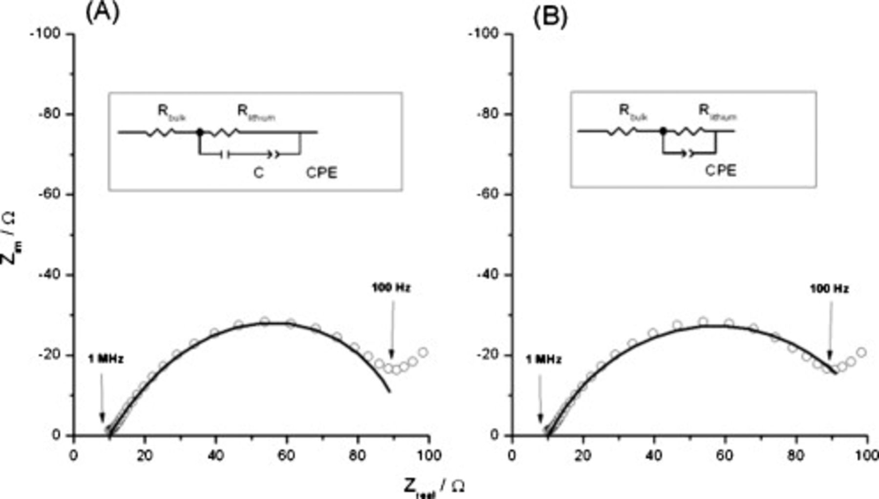
Figure 4. Impedance spectra of a symmetrical cell containing  and
and  LiTFSI and theoretical fits using two equivalent circuits (shown as insets) recorded over a frequency range of 10 MHz to 10 mHz at room temperature. A limited frequency range was fitted.
Table II. Impedance spectroscopy results for Li/Li symmetrical cells constructed using FSI-based electrolyte solutions. All impedance spectra were run on freshly constructed cells.
| RTIL | Lithium salt | Concentration
| Temperature
|
 
|


|
 
|
|---|---|---|---|---|---|---|

| LiTFSI | 0.5 | 50 | 2.4 | 1.3 | 12 |

| LiTFSI | 0.5 | 20 | 7.6 | 2.5 | 33 |

|

| 0.5 | 20 | 6.7 | 1.4 | 64 |
| LiTFSI | 0.5 | 20 | 34 | 9.1 | 680 |

| LiTFSI | 0.5 | 20 | 2.4 | 1.4 | 110 |

| LiTFSI | 0.5 | 20 | 8.5 | 1.6 | 270 |

| LiTFSI | 1.0 | 20 | 20 | 2.6 | 300 |

|

| 0.5 | 20 | 13 | 1.7 | 1700 |
fCorrected  and
and  values for individual lithium metal electrodes presented in the table.
In IL media, qualitatively similar responses have been reported, as shown by Seki et al.35 for  (
( LiTFSI) and by Sakaebe et al.36 for
  (
( LiTFSI). As noted above, Fig. 4 also shows the same basic features. However, the responses for lithium electrodes in ILs are usually more complicated, as previously described by Howlett et al.37 In terms of the Aurbach model, IL electrolytes give rise to a broader range of resistance and capacitance values (for the
  parallel elements of each layer of the SEI) and a much higher total SEI impedance. As seen in this work, the increased spread of electrical parameters leads to two- and three-semicircle responses, the flattened shape of which requires the use of constant-phase elements (CPEs) to generate acceptable experiment–model fits. A complex electrolyte composition with varied conduction pathways leads to the use of CPEs to describe a heterogeneous dispersion of time constants.37 Thus, the CPE is used to account for the departure from ideality of the capacitance behavior of the interface. For the simplest responses obtained, fitting was carried out with a straightforward equivalent circuit (Fig. 4 inserts), where the main elements correspond to the bulk electrolyte resistance
  , an electrode resistance
  corresponding to the resistance of the SEI layer formed,36 electrode capacitance
  , and a CPE. Attempts to fit the experimental data without the use of a CPE gave inferior results, as shown in Fig. 4B, presumably due to the complex composition of the SEI formed on the lithium surface. For the more complicated EIS responses (v.i.) (see earlier discussion), we have not attempted fitting the more complex models that are required.37 This approach is similar to the one recently used in our study of mixtures of FSI ILs with LiFSI.23
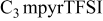
To examine the effect of varying the cation, impedance characteristics were compared for symmetrical cells containing  ,
,  , and
, and  , all with the addition of
  LiTFSI at room temperature (Fig. 5A). As expected, values of
  (electrolyte resistance) for the three mixtures were similar (Table II), in line with the conductivity data for the pure ILs.14 The comparison of values of
  , however, revealed significant differences, with the highest
  observed for
  , while
  showed a much lower
  value
value  , and that for
  was lower still
  . Clearly, the only difference between these symmetrical cells is the IL cation present. Repeating these measurements using
  showed a similar trend, a decrease in the cell impedance going from
  to
to  (Fig. 5B). However, there are also significant differences in
  for the same cation, but with different anions (Table II). With
  , the electrode impedance shifts from
  (LiTFSI) to
 . Similarly (though by a smaller factor), for
  , the corresponding shift is from 33 to
  . Thus, the differences in cell impedance cannot be solely attributed to the differences in the bulk liquid properties of the IL; the identity of the anion in the added lithium salt exerts a major effect, presumably through its contribution to the characteristics of the SEI, as noted in the earlier discussion.
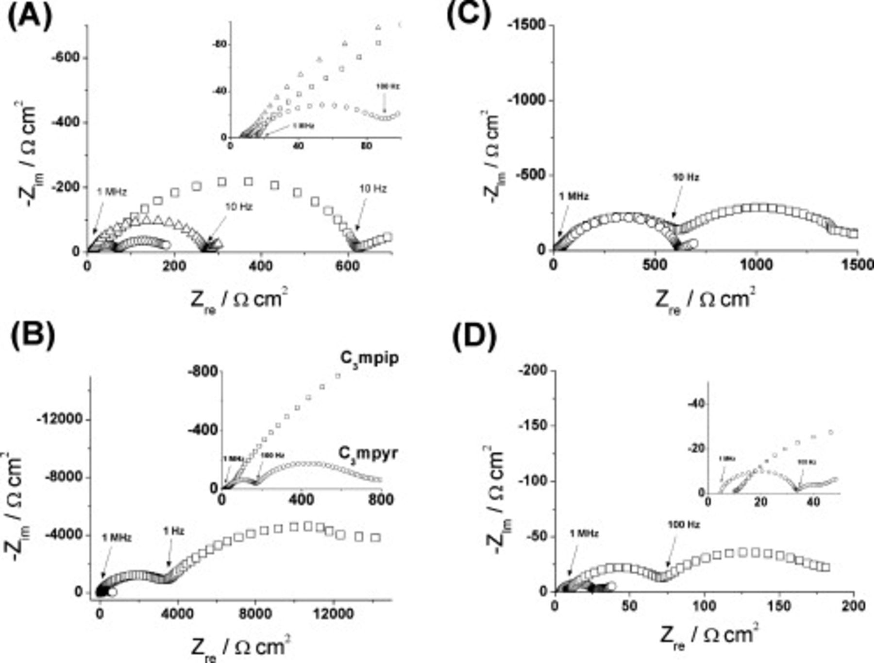
Figure 5. Impedance spectra of symmetrical cells constructed using FSI-based IL electrolytes recorded over a frequency range of 10 MHz to 10 mHz at room temperature. (A)  with
with  LiTFSI (◻),
  with
with  LiTFSI (○), and
  with
with  LiTFSI (△); (B)
  with
with 
 (◻) and
  with
with 
 (○); (C)
  with
with  LiTFSI (○) or
  LiTFSI (◻); (D)
  with
with  LiTFSI at room temperature (◻) and at
  (○).
(○).
The effect of a given lithium salt is also related to concentration, as illustrated for  with LiTFSI added (Fig. 5C). While the high frequency region is similar (see Table II for fitting parameters) between the two concentrations, a second semicircle appears for the
  concentration of LiTFSI appears in the low frequency region attributed to an appreciable increase in electrode impedance.
Temperature effects on cell impedance have also been investigated for the  and LiTFSI system (Fig. 5D). At room temperature, an
  value of
  is measured. However, by increasing the cell temperature to
  the
the  value drops to
  . This effect is consistent with the increase in temperature causing a decrease in electrolyte viscosity and a concomitant increase in conductivity.
By comparing the impedance spectra of  against
  , as shown in Fig. 6, the results obtained for the symmetrical cells show that the FSI–TFSI electrolyte exhibits much lower total cell impedance than the all-TFSI electrolyte.
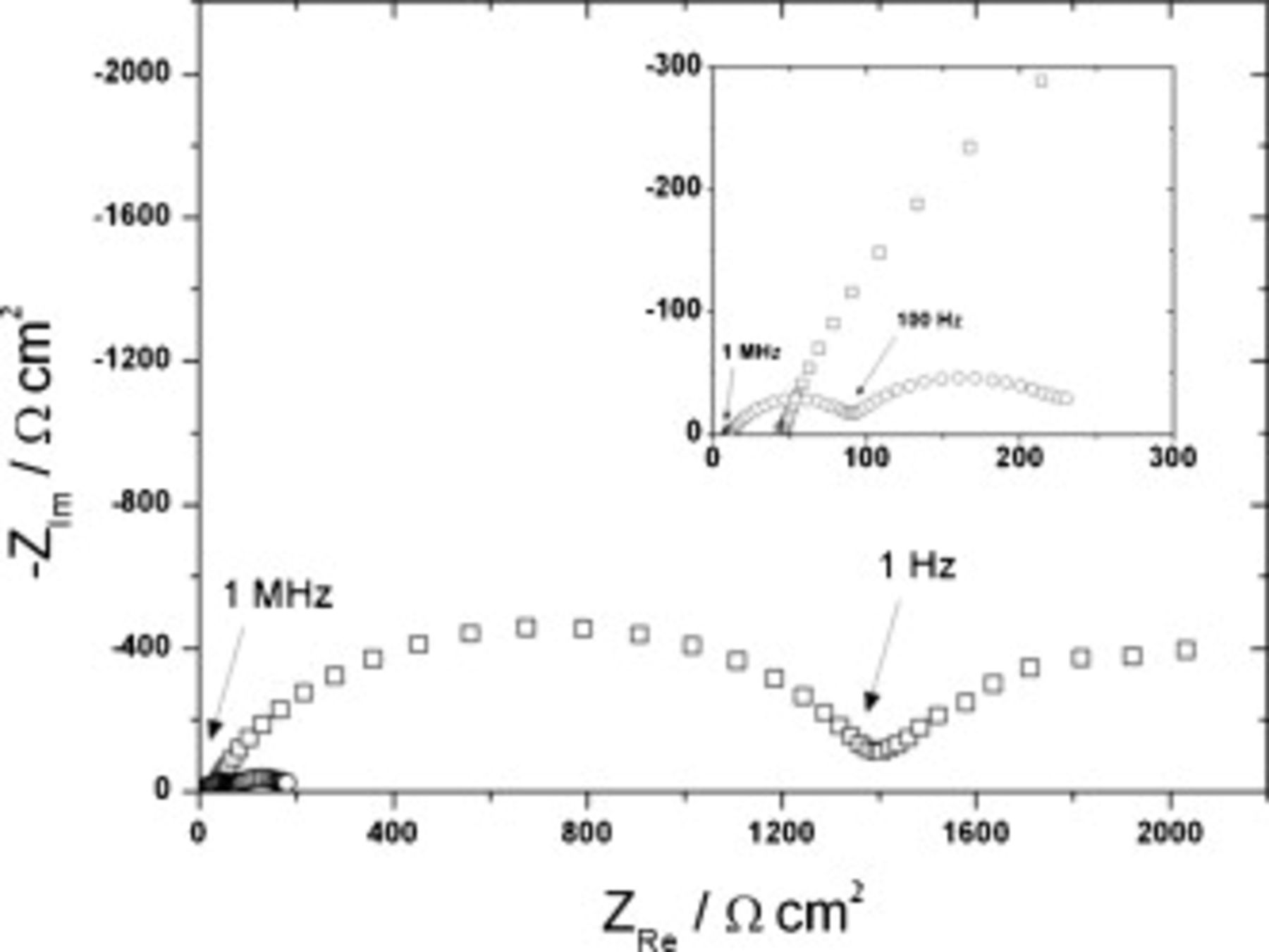
Figure 6. Impedance spectra of symmetrical cells constructed using  with
with  LiTFSI (○) or
  with
with  LiTFSI (◻) and recorded over a frequency range of 10 MHz to 10 mHz at room temperature.
Time dependence of impedance of Li symmetrical cells
The magnitudes of impedance shown in Fig. 4, 5 and 6 are all of the order of one to several hundred  . However, these quite high values do not persist beyond the first 10 cycles of the symmetrical cells; in all cases, cell impedances fall to much lower values. A typical example is provided in Fig. 7A, which shows the EIS outputs from the initial state through to the completion of 300 charge–discharge cycles. It is seen that the impedance falls sharply during the first eight cycles, and ultimately reaches values of
  during the longer term cycling, as shown in Fig. 7B. Figure 7B also shows that cell impedance shows little change over 300 cycles at rates up to
  . In terms of incorporating a
  IL electrode into a functioning device, the behavior described here could be an appropriate number of conditioning cycles before the commencement of normal service.
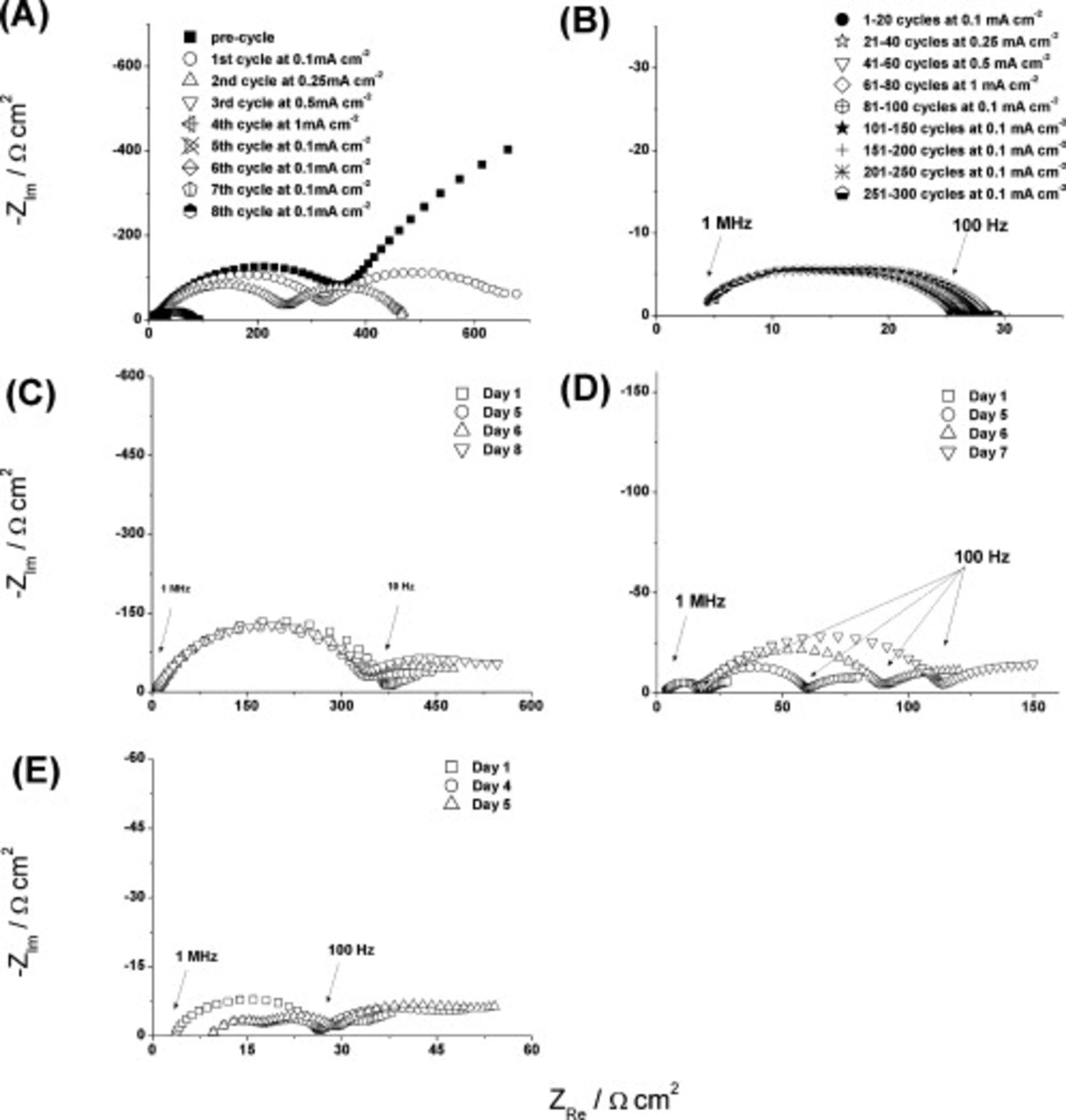
Figure 7. Impedance spectra of symmetrical cells constructed using FSI-based IL electrolytes and recorded over a frequency range of 10 MHz to 10 mHz. (A) Impedance spectra after cycling cell containing  with
with 
 at room temperature recorded after each cycle at the stated current densities and which comprise the first eight cycles before long-term cycling. (B) Impedance spectra recorded after long-term cycling of cell at varying current densities (as shown in figure legend) containing
  with
with 
 at room temperature; cycling started immediately after recording data for plot (A). (C)
  with
with  LiTFSI at room temperature, impedance spectra recorded after 1, 5, 6, and 8 days (no cycling performed). (D)
  with
with  LiTFSI at
  , impedance spectra recorded after 1, 5, 6, and 7 days (no cycling performed).
To determine whether FSI-based ILs could be used as electrolytes in lithium-metal batteries, the impedance spectra of Li–Li symmetrical cells were also recorded as a function of storage time, at different temperatures. With  (
( LiTFSI) as the electrolyte at room temperature, virtually no change in the cell impedance occurred over 8 days (Fig. 7C). This result indicates that at room temperature, the FSI-based electrolyte establishes an SEI on lithium metal that is stable for at least 8 days. However, when repeated with a replicate cell at
  , the low initial cell impedance increases progressively over the next 7 days (Fig. 7D). The spectrum (depressed semicircle) changes little with time. Rather, the magnitude of
  steadily increases, which suggests that the SEI is simply becoming thicker. Even after 7 days, the total cell impedance at
  is still well below that measured at room temperature (Fig. 7C). Presumably, in the former case, although the SEI is probably thicker,38 the component of the RTIL electrolyte resistance included is lower due to the higher conductivity at the higher temperature, and this then offsets the thickness-based resistance increase to some extent.
Analysis of cycling performance of lithium symmetrical cells
The ability of these systems to undergo repetitive charge–discharge cycling was quantified by recording the voltage–time characteristics of a series of symmetrical Li–Li coin cells as a function of galvanostatic load (charging and discharging). The voltage–time profiles for selected mixtures of  ,
,  , and the lithium salt
  ,
,  , or LiTFSI in symmetrical cells are shown in Fig. 8.
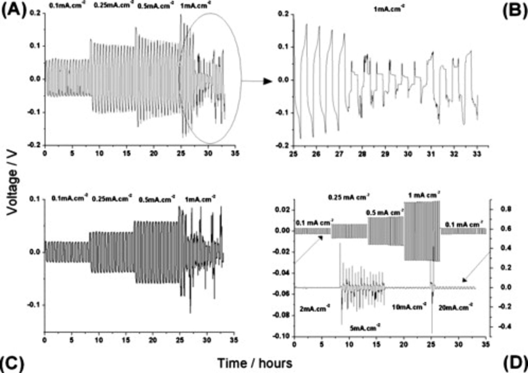
Figure 8. Voltage–time profiles for symmetrical cells with varying constant current charging/discharging: (A)  and
and  LiTFSI at
  , (B) an expanded plot of (A) showing the transient behavior in closer detail, (C)
  and
and 
 at
at  , and (D)
  and
and 
 at room temperature. Upper: Initial cycles at low current densities and lower cycles at high current density.
Each set of responses in Fig. 8 is comprised of the voltage response of the cell to a galvanostatic square-wave profile that changes sign every 16 min. There were no rest periods between applications of current, either for changes of sign or as the magnitude was changed. As described earlier, the impedance of these Li–Li symmetrical cells falls significantly during the initial phase of charge–discharge cycling. In Fig. 8A, for a cell with  and
and  LiTFSI, this fall is apparent from an inspection of the average maximum voltage as the current increases up to
  . The effective resistance of this particular cell was initially
  and falls to approximately
  within 50 cycles. In the next stage of cycling, at the higher current density
  , the resistance continues to fall, resulting in an unstable voltage response.
On closer inspection of the voltage–time curves in the unstable region (Fig. 8B shows an expanded plot of Fig. 8A), apparently, the predominant shape for a given current period has a fixed voltage value (becoming progressively lower as cycling progresses) upon which is superimposed one or more large rapid increases ("spikes") in the voltage. This feature occurred with many of the symmetrical cells examined in this study and always early in the cycling schedule. In no case, however, did these transients persist for more than 10–20 cycles, after which the cells revert to functioning with a smooth voltage profile.
Based on the observed characteristics, we suggest that both the steady fall in cell resistance and the voltage spikes are associated with the formation of a dendritic lithium morphology,39, 40 which at some point becomes unstable. In the early stages, dendrite formation expands the surface area of the electrode, thereby lowering the current density. As a result, the maximum voltage falls. Eventually, with continued growth of dendrites, parts of the structure become detached from the electrode (due to localized heating where current density becomes very high), and there is an instantaneous increase in voltage due to the rise in current density on separation of part of the electrode. The rise in voltage is not permanent though because the dendritic growth and detachment occur within a relatively small volume, which is bounded by the separator and the electrode SEI and held under the stack pressure imposed by the coin cell spring. It is then reasonable to suggest that the detachment of a portion of electrode is quickly followed by this portion re-establishing contact with the electrode nearby. This would account for the somewhat random nature of the voltage transients and their variable duration for these periods of charge–discharge cycling. In a forthcoming publication,38 we provide more support for this explanation, by showing cross-sectional images of cycled electrodes in which the remnants of this branched morphology are clearly visible.
Other examples of voltage–time responses for symmetrical cells with different combinations of IL, lithium salt, and operating temperature, which also fit the pattern of behavior described here, are provided in Fig. 8. With  and
and 
 , cycled at
  (Fig. 8C), the behavior is virtually identical to that observed in Fig. 8A. Importantly, as noted in the earlier discussion, the
  -based electrolyte generates lower symmetrical cell impedance than the corresponding
  system (Fig. 4A). Hence, it is not surprising that an analysis of the voltage curves in Fig. 8C returns markedly lower values of cell resistance around
  (based on the first period of cycling). Changing the lithium salt to
  gives the responses shown in Fig. 8D. In the upper section of this plot, there is no sign of the voltage fluctuations discussed earlier, even as the cell is operated through the same sequence of current density as employed for Fig. 8A. However, on increasing the charge–discharge currents substantially (lower portion of plot), the voltage profile does begin to vary widely. As stated earlier though, the fluctuating behavior only persists for a few cycles after which a smooth voltage output is restored. This suggests that when
  is the added salt, the formation of dendritic morphology is inhibited, though not completely suppressed. As already shown in Fig. 7A, the EIS spectra recorded during the first phase of cycling of this cell (upper plot in Fig. 8D) still show a decrease in cell impedance during the first 50 cycles, of a similar order to that seen for other cells.
Conclusions
From the cyclic voltammetric study of ILs based on the FSI anion, those with the pyrrolidinium and phosphonium cations afford the best cathodic stability. Anodic limits are sufficient to accommodate the commonly used cathode materials and appear ultimately to be set by both the cation and anion, courtesy of a complex electro-oxidation mechanism.
When various Li salts are dissolved into FSI ILs, a substantial extension of the cathodic limit occurs, and highly reversible electrodeposition and stripping of lithium can be achieved. The most stable behavior was exhibited by a mixture of  and
and 
 . As the temperature is raised, this stabilization is offset by a shift of the cathodic limits back toward less negative values presumably due to acceleration of kinetically controlled degradative processes, and ultimately lithium electrodeposition is no longer observed. Importantly, our results also show that the TFSI anion does not have to be present to achieve reversible lithium electrochemistry at metal electrodes.
Impedance spectroscopy conducted on a series of Li–Li symmetrical cells shows that the total cell impedance is a function of IL cation, Li salt (identity and concentration), and operating temperature. In all cases examined, FSI ILs yield total cell impedances that are markedly lower than those for the equivalent TFSI-based cells. Galvanostatic cycling of symmetrical coin cells shows that FSI-based ILs with one of three lithium salts are capable of supporting stable operation over a range of current densities. For example, a mixture of  with
with 
 can support lithium plating/stripping current densities of
  . For most systems, early in cycle life, evidence is found in the voltage–time curves of the formation of dendritic morphologies, which causes significant voltage instability. Future work aims to present more details of how the morphology of lithium electrodes evolves during the complex electrochemical behavior that occurs early in charge–discharge cycling.40 In all cases, though, this behavior is transient and cells emerge displaying lower resistance, as calculated from the maximum step voltage and the applied current density. The trends in this resistance mirror those from EIS measurements and thereby offer a useful alternative to a full-spectrum impedance analysis.
This study has shown that several FSI ILs can be the basis for viable electrolytes for a rechargeable lithium-metal battery technology. The FSI anion provides the essential property of allowing a durable SEI to form, while the choice of Li salt and IL cation provides a scope for fine-tuning the cycling characteristics, depending on the intended operating conditions.
Acknowledgments
The authors gratefully acknowledge A. P. Lewandowski and P. Kao for assistance with the construction of Li:Li symmetrical cells.
Commonwealth Scientific and Industrial Research Organisation assisted in meeting the publication costs of this article.