Abstract
A lithium ion battery cathode structure was produced which has the potential for excellent capacity retention and good thermal management. In these cathodes, the active cathode material (lithium iron phosphate) was carbon bonded to a thermally and electrically conductive carbon fiber paper (CFP) support. Electrochemical testing was performed on Swagelok cells consisting of CFP cathodes and lithium anodes. High specific energy, near-theoretical capacity, and good cycling performance were demonstrated for 0.11 and  thick CFP cathodes.
Export citation and abstract BibTeX RIS
Lithium ion batteries have been an overwhelming commercial success for portable electronic devices. However, the limited cycle life and thermal accidents (e.g., thermal runaway, ruptures) of lithium ion batteries are significant concerns for these small batteries and are even greater concerns for large-scale batteries. The automotive industry is on the verge of launching the commercial scale production of several plug-in hybrid electric vehicles and electric vehicles (EVs) using large modules of lithium ion cells. The cost of large-scale automotive batteries makes casual battery replacement unfeasible, so excellent cycle life becomes more critical. The US Advanced Battery Consortium established a target cycle life of  at 80% depth-of-discharge for EVs.1 Large lithium ion batteries have a greater potential to have thermal accidents because they have higher total energy content and poorer heat dissipation than smaller cells.2
Typical commercial lithium ion battery cathodes are comprised of an active cathode material (e.g.,  ,
,  ,
,  ,
,  ) and small amounts of conductive carbon black that are bound together and attached to a metal foil current collector using a polymeric binder. Electrical conduction in a typical commercial cathode occurs from the active material through percolating carbon black additive to the metal current collector. The electrical pathways are held together with polymeric binder and not with robust chemical bonds. Capacity fade during battery cycling can occur due to the inability of the polymeric binder to hold together the conductive pathway to the active material during cyclic swelling of the active material.3 Thermal accidents can occur when localized short circuits in the cathode area (due to lithium dendritic growth, puncture accidents, etc.) cause a sufficient localized temperature increase to initiate propagating exothermic chemical reactions between the electrodes and electrolyte.4 The polymerically bound powders in a commercial cathode conduct heat poorly, which promotes localized temperature increase near short circuits or points of high current density.
Research at Oak Ridge National Laboratory (ORNL) has produced cathodes with active cathode material carbon bonded to thermally and electrically conductive porous carbon supports, including open cell foams and carbon-bonded carbon fiber structures.5, 6 In this study, carbon fiber papers (CFPs) were used as a support to produce CFP cathodes. Lithium iron phosphate  was used as the active cathode material because of its high stability in overcharge and elevated temperature conditions.7 The conductive carbon support and rigid carbon bonding of CFP cathodes potentially enable (1) superior thermal management due to the rigid thermally conductive structure dispersed throughout the cathode layer; (2) improved cycle life due to rigid carbon bonding of the active cathode material with the current collector; and (3) a higher electronic transport through the composite free of binders and flaws caused by compaction pressures.
To our knowledge, utilizing carbon fibers as the cathode current collector has not been reported elsewhere. There have been promising studies where carbon fibers were used as the active anode material.8–11 Proposed advantages of the carbon fiber materials as anodes included good thermal conductivity, low surface area, absence of binder and copper, and overcharge protection.8, 9 The carbon fibers have also been coated with carbon nanotubes for enhanced performance.10 Because of their structural integrity, carbon fiber anodes have also been suggested for potential use in multifunctional materials, which both store electrical energy and provide load-bearing capability.11 Metal fiber additives have been demonstrated in cathodes; small amounts of micrometer-scale stainless steel fibers  have been demonstrated to improve the cycling and rate performance of
  cathodes.12
Experimental
The two different CFPs used as cathode supports were produced by Toray Industries: TGP-H-030 and TGP-H-120. These carbon-bonded polyacrylonitrile carbon fiber papers are used in fuel cell applications due to their mechanical integrity, electrical and thermal conductivity, and gas permeability. A list of key physical properties is provided in Table I, as provided by the manufacturer. CFP disks ( diameter) were cut out of sheets by striking a cork borer with a hard plastic faced hammer.
Table I. Properties of CFP materials as supplied by the manufacturer.
| TGP-H-030 | TGP-H-120 | |
|---|---|---|
| Thickness (mm) | 0.11 | 0.37 |
Bulk density 
| 0.40 | 0.45 |
| Porosity (%) | 80 | 78 |
Electrical resistivity in-plane 
| — | 4.7 |
Thermal conductivity in-plane ( at room temp.) at room temp.) | — | 21 |
The lithium iron phosphate was synthesized using a sol gel technique, based on the recipe of Hu et al.13 The sol gel contents were:  phosphoric acid (Sigma-Aldrich, 99.999%, 85% solution in water),
  deionized water,
  lithium acetate dihydrate (Sigma),
  iron(III) nitrate nonahydrate (Sigma-Aldrich, 98%),
  glycolic acid (Sigma-Aldrich, 99%), and approximately
 (adjusted to
  5) (Mallinckrodt, 58%). The solution was gelled at
  . The gel was calcined at
  . In addition, commercial
  material with
  carbon was obtained from HydroQuebec (HQ).
Coating slurries were created by mixing  -vinyl-2-pyrrolidone (Polysciences Inc. 99%), AR mesophase pitch (Mitsubishi Gas Chemical Company), and the
  powder. During processing development, the pitch-to-powder ratio was kept constant (0.034), but the weight percent of
  in the slurry was varied from
  . Two solids loadings were chosen for extensive study based on a balance between viscosity and active cathode material content: 26 and
 .
.
CFP disks were manually coated with slurry, and excess slurry was carefully removed from the surface. Variability in surface slurry removal accounted for some sample-to-sample variation in  loading. Slurry-coated disks were dried at
  and then heat-treated to
  to carbonize the AR mesophase pitch. The heat-treatment temperature was chosen to maximize the pitch carbonization while minimizing the grain growth and thermal decomposition of
  .14 For cathodes using ORNL
  powder, energy dispersive X-ray analysis (EDAX) and atomic emission combustion analysis were used to determine that the final coating material had approximately
 and
and  carbon (coming from both the sol and the pitch). For cathodes using HQ
  powder, the carbon content came from the as-received powder and the pitch, so the final coating material had approximately
 and
and  carbon. The carbonized CFP disks were used as cathodes in lithium ion cells.
Swagelok cells were constructed with each CFP cathode for battery testing. The Swagelok cells were made of  perfluroroalkoxy Swagelok bored-through compression union tee fittings. A cell was comprised of a
  diam. lithium metal anode (Alfa-Aesar,
  thick 99.9% metals basis), a Celgard 2325 separator (a porous trilayer sandwich of polyethylene inside polypropylene), a CFP cathode, and approximately
  of electrolyte solution (Ferro Corporation,
 ,
,  ethylene carbonate,
  ethyl methyl carbonate). The cell stack was between a fixed 316 stainless steel ram and a spring loaded 316 stainless steel ram inside the tee fitting. The rams were machined to receive standard banana plugs for electrical contacts to the Swagelok cell.
Swagelok cells were tested using a Maccor series 2000 battery test system. Two types of battery tests were performed: constant current discharge tests and C/2 cycle tests. Constant current discharge tests were used to measure the discharge behavior (down to 2.5 or  ) and capacity (reported for discharge only to
  ) as a function of discharge current. Batteries were discharged at 2, 1, 0.5, 0.1, 0.05, 0.02,
  , and sometimes also additional higher currents up to
  . C/2 cycle tests were used to determine capacity fade with cycling. C-rate was calculated using the capacity measured in a low current
  discharge. In the C/2 cycle tests, 100 charge/discharge cycles were performed using constant current at the C/2 rate, except for every 20th cycle done at a C/30 rate. The C/30 cycles were used to differentiate loss of active material from internal resistance changes. For both types of tests, charges were performed at
  up to
up to  and were ended when the charge current dropped to
  .
.
Results
Successful infiltration with coating slurries was observed for 0.11 and  thick CFP disks. Figure 1 shows scanning electron microscopy (SEM) images of top surfaces and fracture cross-sections of CFP cathodes. Both the
  slurry and the
  slurry penetrated into the center of the papers. The increased loading achieved by using the
  slurry as opposed to the
  slurry could be readily observed in these SEM images. The estimated average porosities of the different CFP cathodes were calculated and summarized in Table II. The slurry did not fully coat the carbon fibers. The slurry with HQ powder did coat the carbon fibers slightly better than the slurry with ORNL powder presumably because of the uniform small particle size of the HQ powder (Fig. 2). Primarily, the slurry dried and carbonized to make coating "webs" (films) between neighboring carbon fibers. Some of these apparent coating "webs" were actually carbon "webs" originally present in the Toray paper that were coated with slurry. Regions of excess coating were observed lying on the top and bottom surfaces of the CFP cathodes. In all samples, the void volume available for the electrolyte was large.
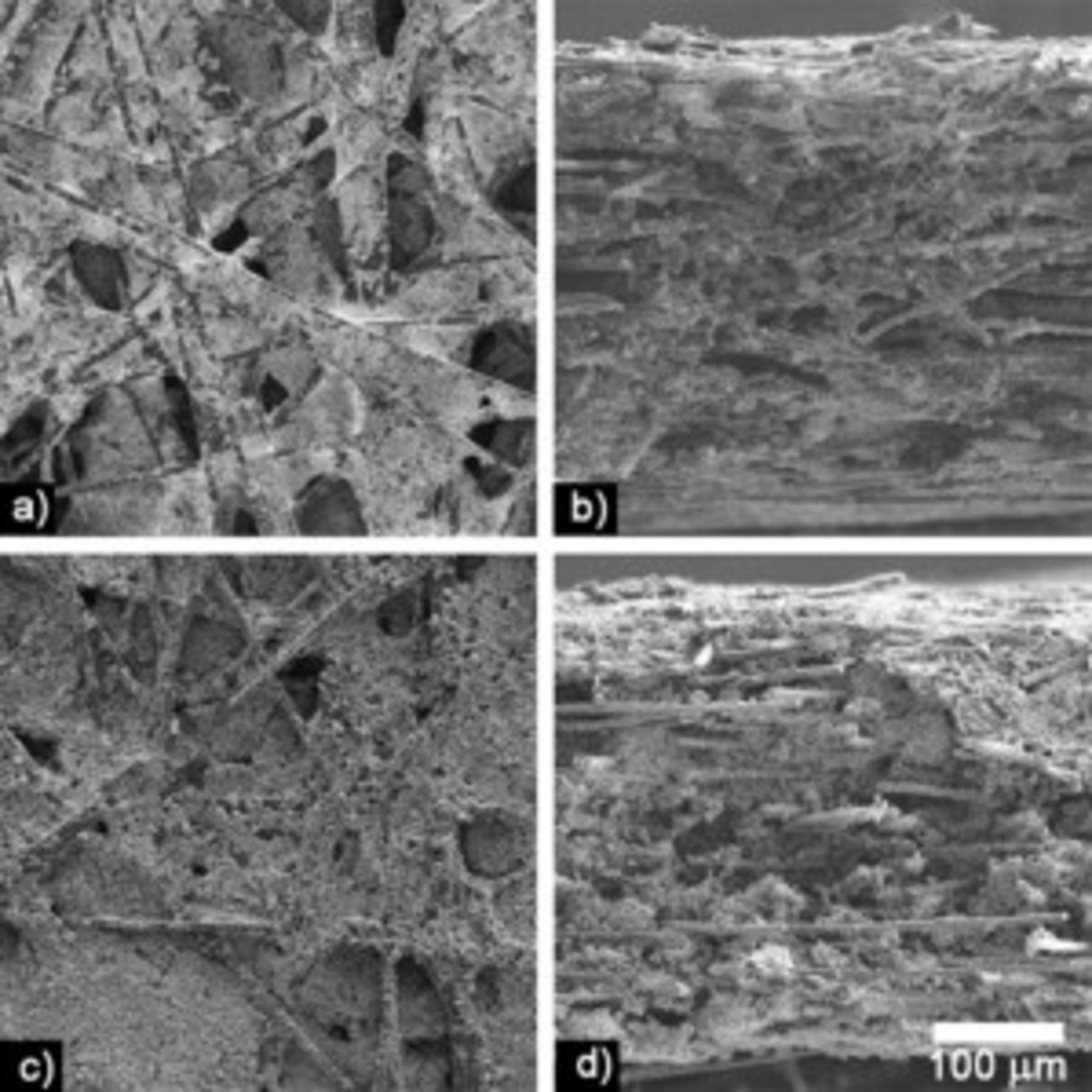
Figure 1. SEM images of  thick CFP cathodes at the same magnification.
  slurry cathodes: (a) flat surface and (b) fracture cross section.
  slurry cathodes: (c) flat surface and (d) fracture cross section.
Table II. Average  loading and porosity of each type of cathode.
| Slurry composition (wt %) |
 thick CFP thick CFP |
 thick CFP thick CFP | ||
|---|---|---|---|---|
wt %  in cathode in cathode | Porosity (vol. %) | wt %  in cathode in cathode | Porosity (vol. %) | |
| 26 ORNL | 39 | 74 | 33 | 66 |
| 41 ORNL | 55 | 60 | 44 | 59 |
| 41 HQ | 43 | 69 | 42 | 63 |
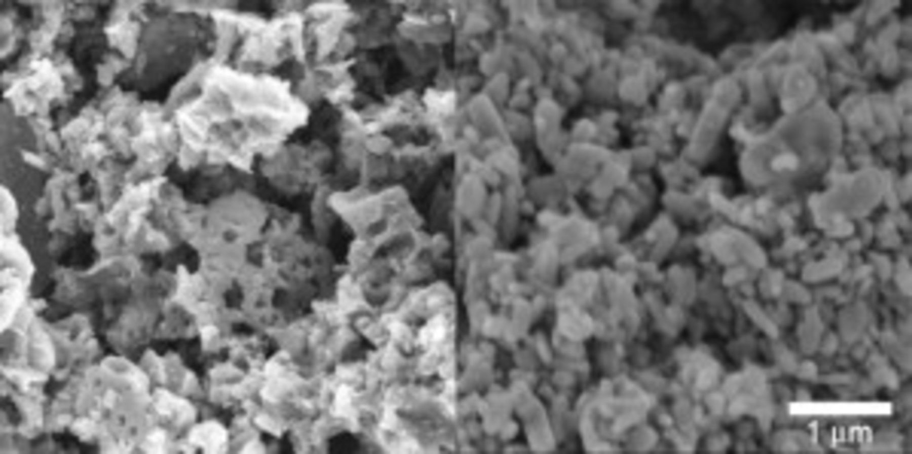
Figure 2. SEM images of the carbonized coatings using ORNL (left) and HydroQuebec (right) powders. Unlike the ORNL powder, HQ powder had distinct well-shaped particles that were small and fairly uniform in size.
X-ray tomographs (Fig. 3) were used to effectively render nondestructive cross sections of a CFP cathode. Because the X-ray tomographs were constructed from multiple radiographs of an intact whole cathode, views of two-dimensional interior slices were obtained which clearly show the relative amounts of bare fibers, coated fibers, webs, and void space without seeing the topography effects and polishing damage of conventional cross-sectional microscopy. The void volume and uncoated fiber surfaces were more noticeable in the X-ray tomographs than in the SEM micrographs.
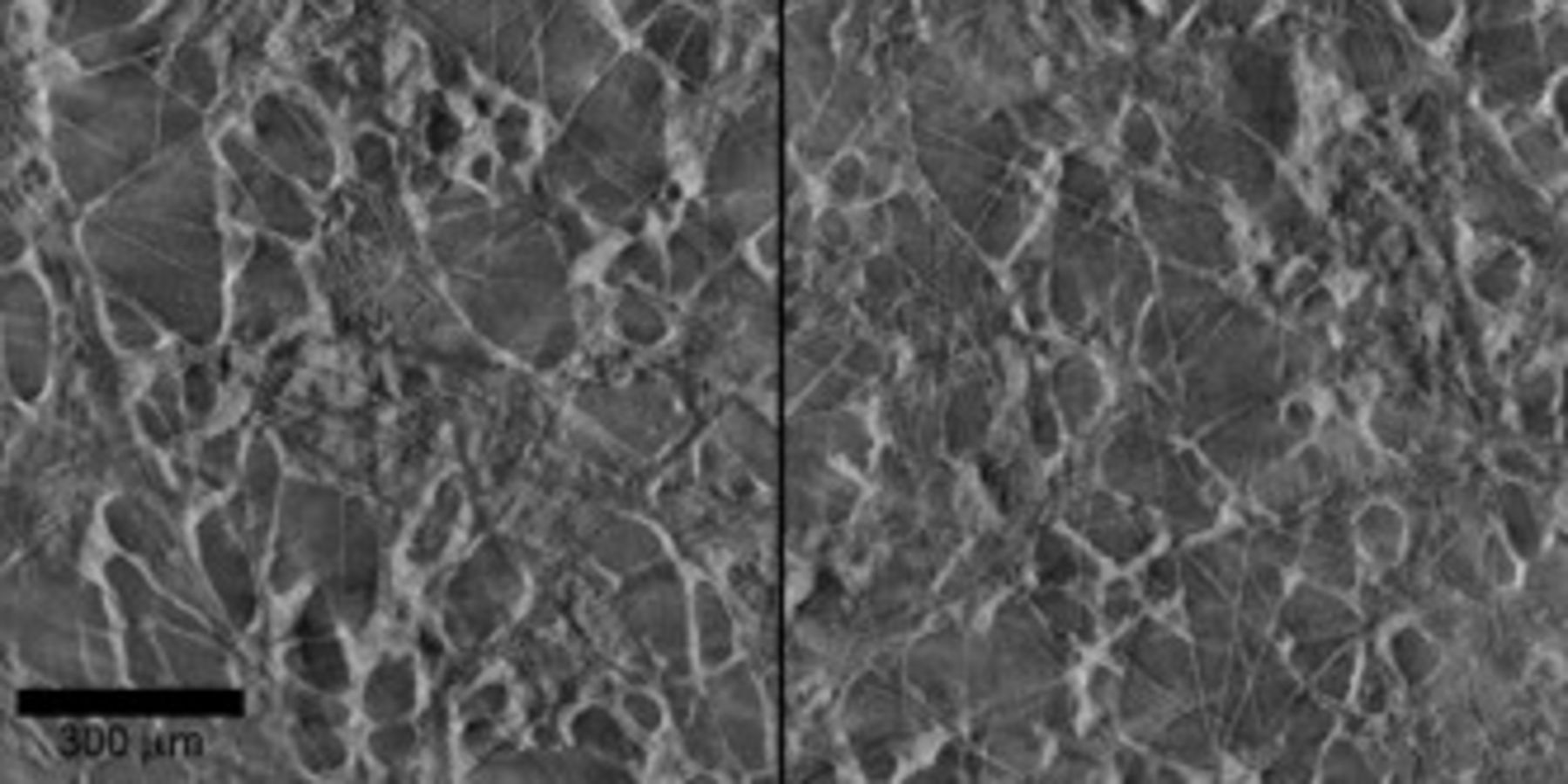
Figure 3. X-ray tomographs showing nondestructive cross sections of  thick CFP cathodes made with
  slurry: near surface (left) and near midplane (right).
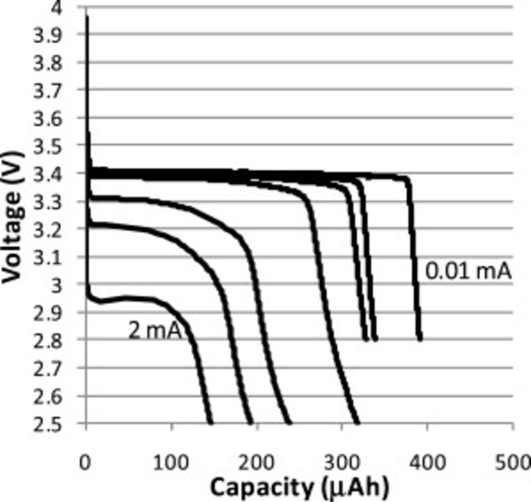
Figure 4. Constant current discharge curves for Swagelok cell with  thick CFP cathode made using a
  HQ slurry. The currents for these discharge curves were 2, 1, 0.5, 0.1, 0.05, 0.02, and
  (left to right).
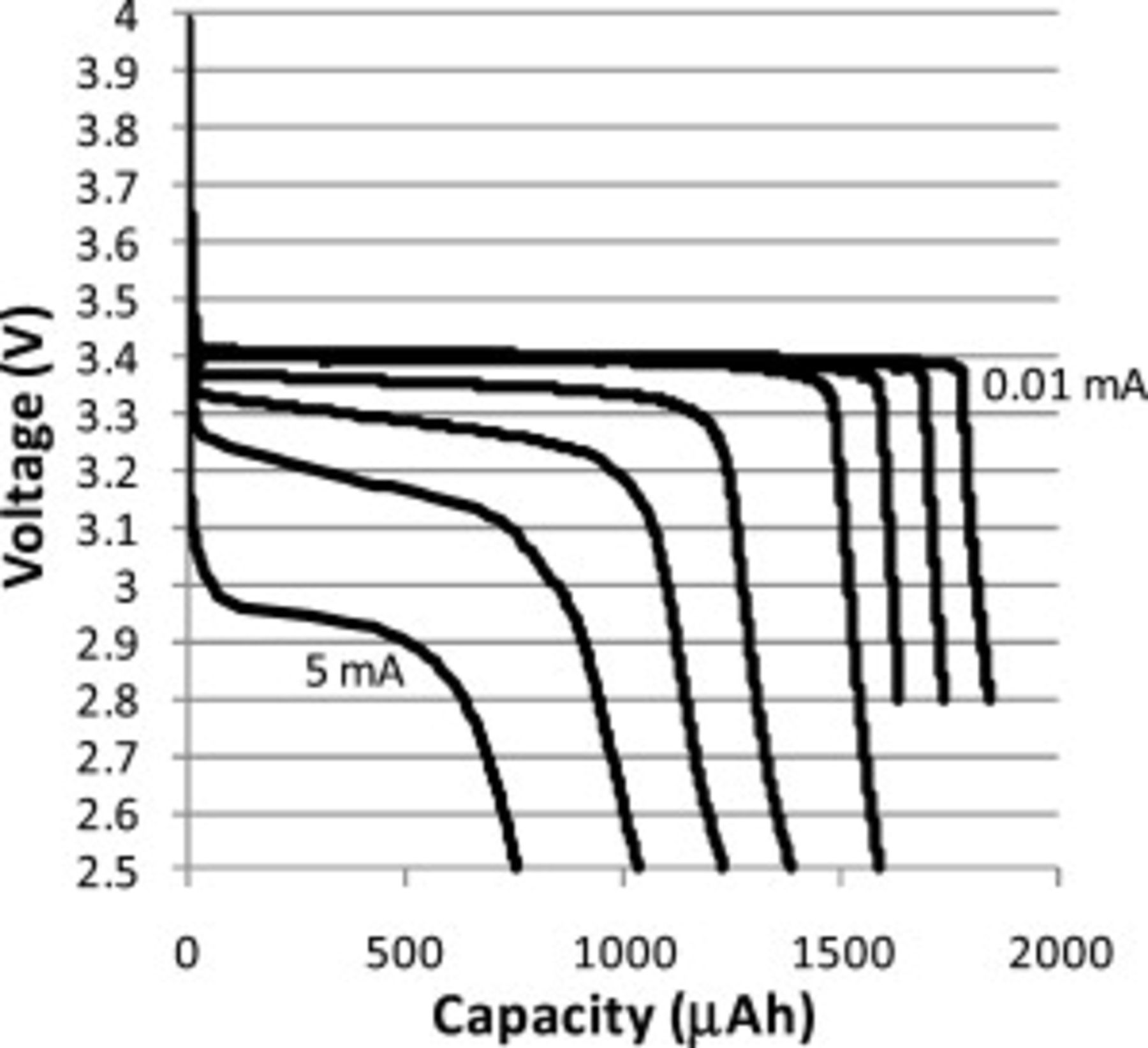
Figure 5. Constant current discharge curves for Swagelok cell with  thick CFP cathode made using a
  HQ slurry. The currents for these discharge curves were 5, 2, 1, 0.5, 0.1, 0.05, 0.02, and
  .
.
Constant current discharge curves were measured on all cells. Figures 4 and 5 provide examples of discharge curves for a  thick CFP cathode and a
  thick CFP cathode. When discharged at the slowest current
  to
to  , CFP cathodes with ORNL
  powder typically demonstrated capacities of approximately 70% theoretical capacity on average (theoretical taken as
 ). Under the same conditions, CFP cathodes with HQ
  powder demonstrated capacities of approximately 100% theoretical capacity. It is not known why the HQ powder had significantly greater lithium utilization than the ORNL powder, but possible causes include the uniformly small particle size and chemical uniformity of the HQ powder (Fig. 2).
Constant current discharge curves of different cells were used to compare the effect of: (a) slurry solids loading (Fig. 6) and (b)  powder source (Fig. 7). For slow discharge
  , the solids loading of the slurry affected the capacity, but did not greatly affect discharge curve shape. For fast discharge
  , initially the discharge curves for the cathodes with high solids loading slurry
  were similar to cathodes with low solids loading slurry
  , but the cell voltages dropped further as the discharge progressed. HQ
  powders had steeper voltage drop-offs toward the end of the discharge than ORNL powders. HQ powders were visibly more uniform in size, lacking the small fraction of large grains found in ORNL powders. HQ CFP cathodes also exhibited higher discharge voltages during fast discharge
  .
.
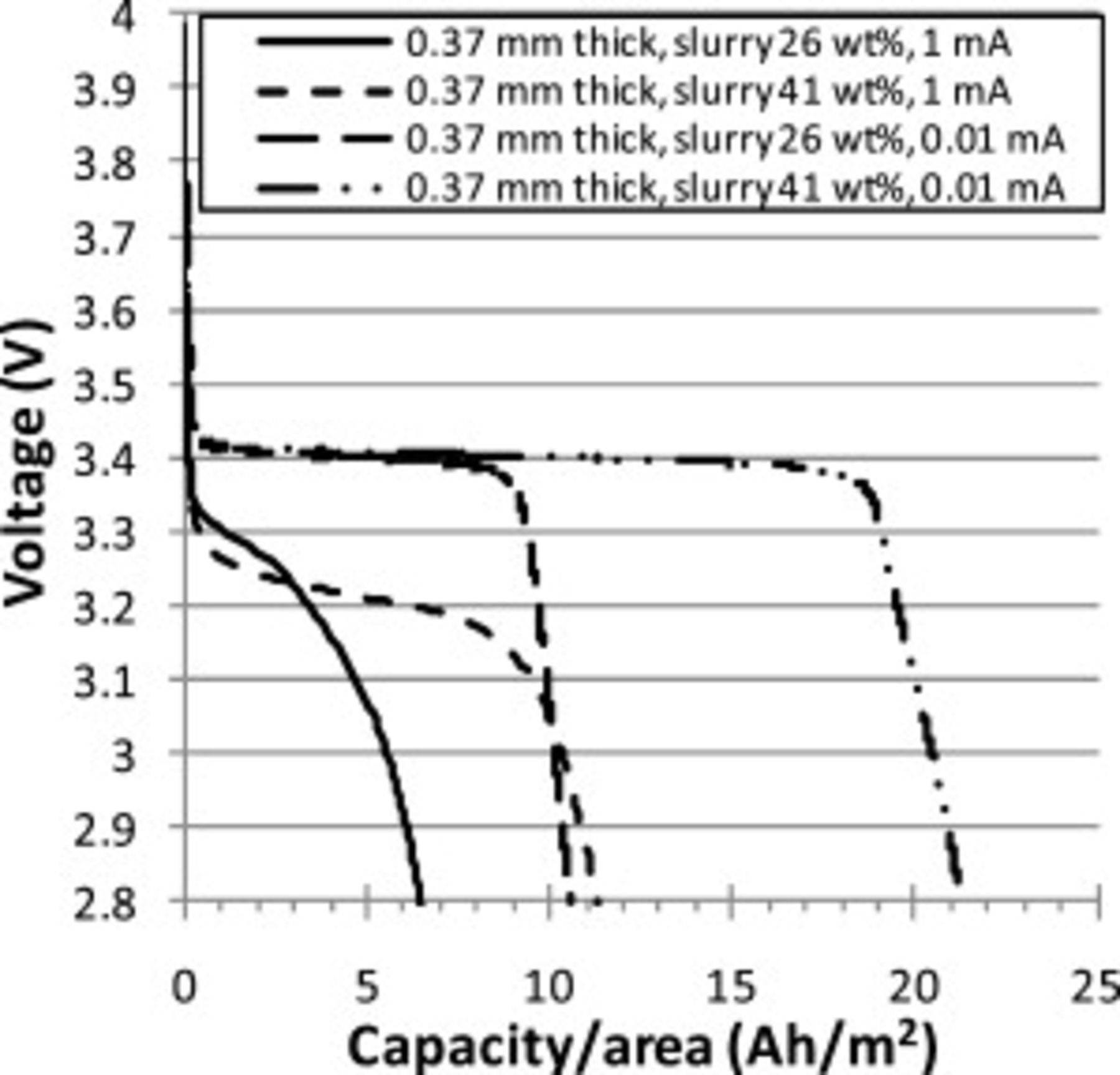
Figure 6. Comparison of constant current discharge curves (1 and  ) for Swagelok cells with
  thick CFP cathodes made using 26 and
  ORNL slurry. Estimated theoretical capacities were 16 and
  , respectively.
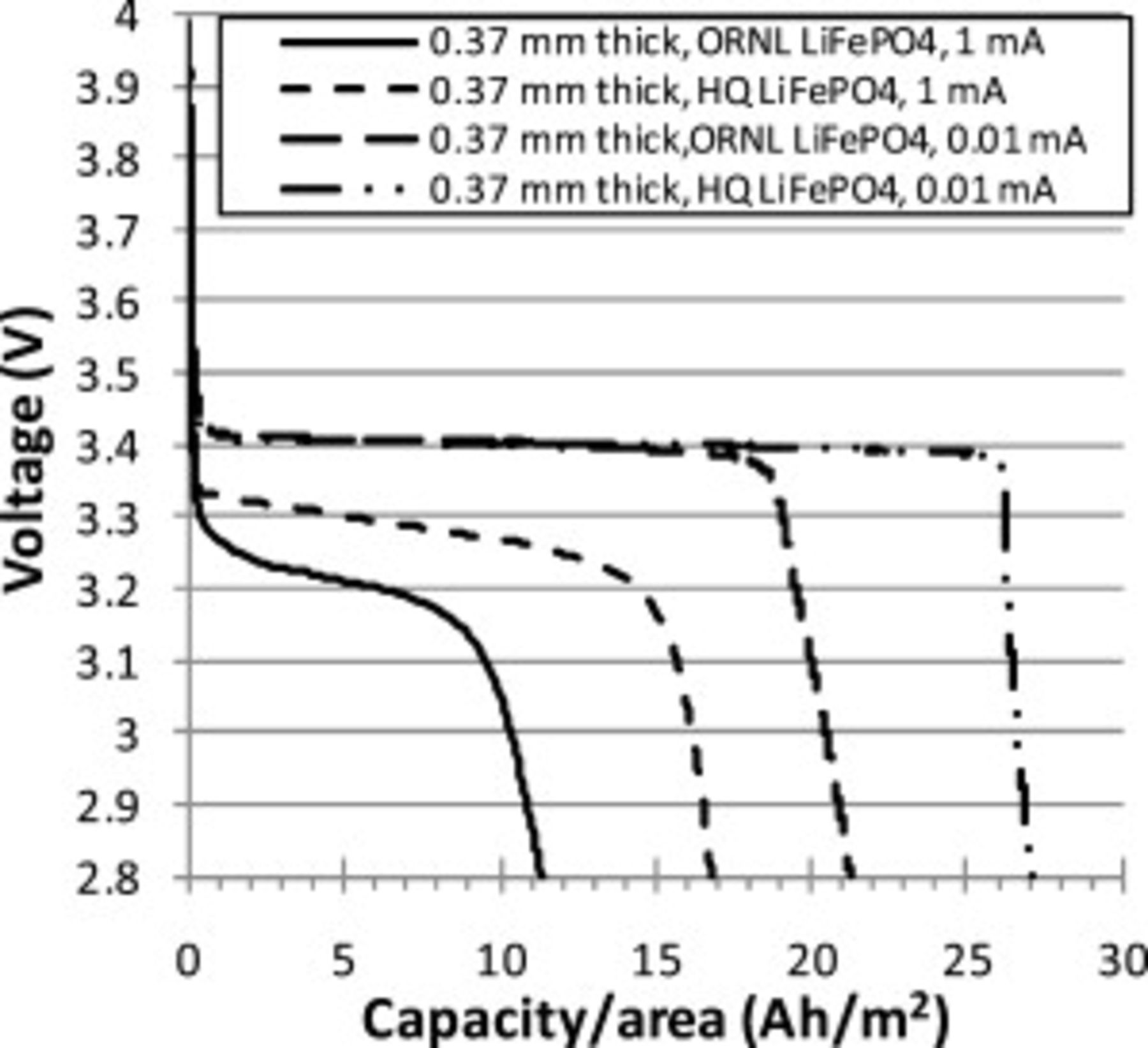
Figure 7. Comparison of constant current discharge curves (1 and  ) for Swagelok cells with
  thick CFP cathodes made using
  slurries of ORNL and HQ
  powders. Estimated theoretical capacities were 26 and
  , respectively.
A Ragone plot of specific energy versus specific power is shown in Fig. 8. Values were normalized by the total weight of the carbon fibers plus active cathode of  with carbon additive. The Ragone plots for
  thick CFP cathodes with ORNL powder showed more rapid decreases in energy at high powers than for the thinner CFP cathodes. This effect is smaller for the cathodes with HQ powders. The CFP cathodes with HQ powders have the highest specific energies, largely because the full theoretical capacity was utilized only for these cathodes.
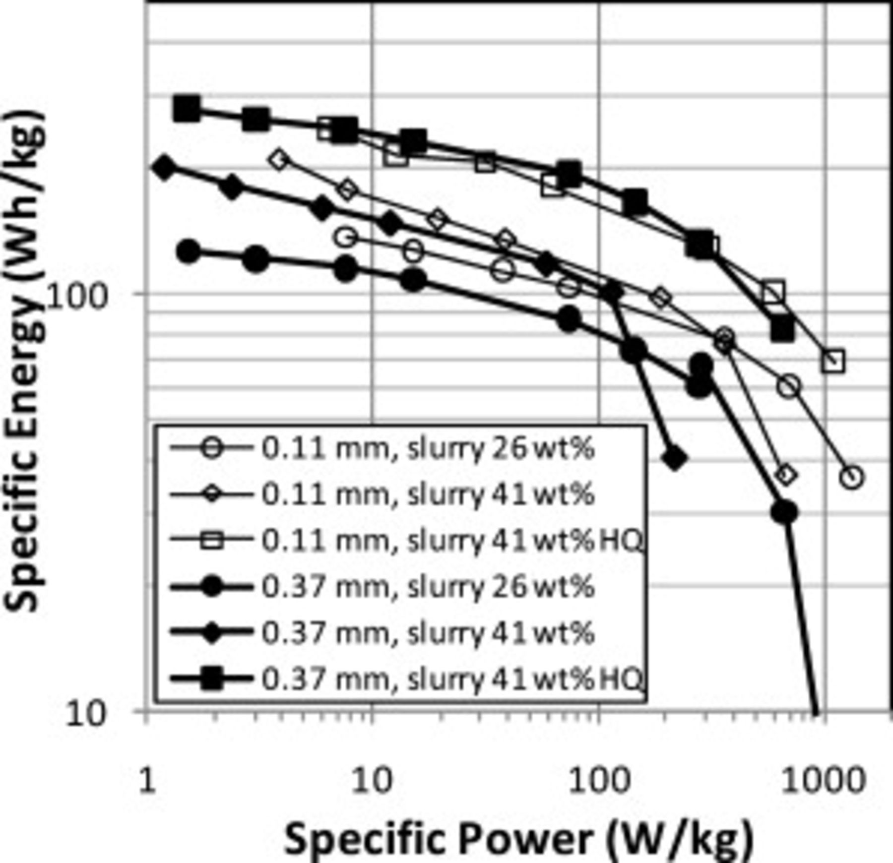
Figure 8. Ragone plot of CFP cathodes.
Cycling results of Swagelok cells with CFP cathodes and lithium anodes varied somewhat from cell-to-cell. This was attributed to degradation of the lithium and variability in the cell assembly. The lithium metal formed a soft coating during battery testing, which was likely dendritic and porous lithium.15 This is exacerbated by the large capacity per unit area of the CFP cathodes. Cathodes in many cases exceeded  , which would correspond to the cycling of more than a
  thick layer of fully dense lithium for each deep cycle. Not surprisingly, a number of cells shorted prematurely, but some cells had excellent cycle performance. A
  thick cathode made from a
 slurry cycled 200 times with only slight fade. Cycle results for two cells with ORNL powder are shown in Fig. 9. For the
  thick cathode made from a slurry with
  ORNL
ORNL  powder, negligible fade occurred during
  and the coulombic efficiency was near 100%. The cell with the thicker cathode containing ORNL powder faded more noticeably, likely due to the lithium degradation. Figure 10 shows the cycle results for the two cells with HQ powder. While both cells showed problems with internal short circuits as evidenced by the erratic spikes in the coulombic efficiency, negligible fade and high coulombic efficiency were observed for 50 consecutive cycles for both cells.
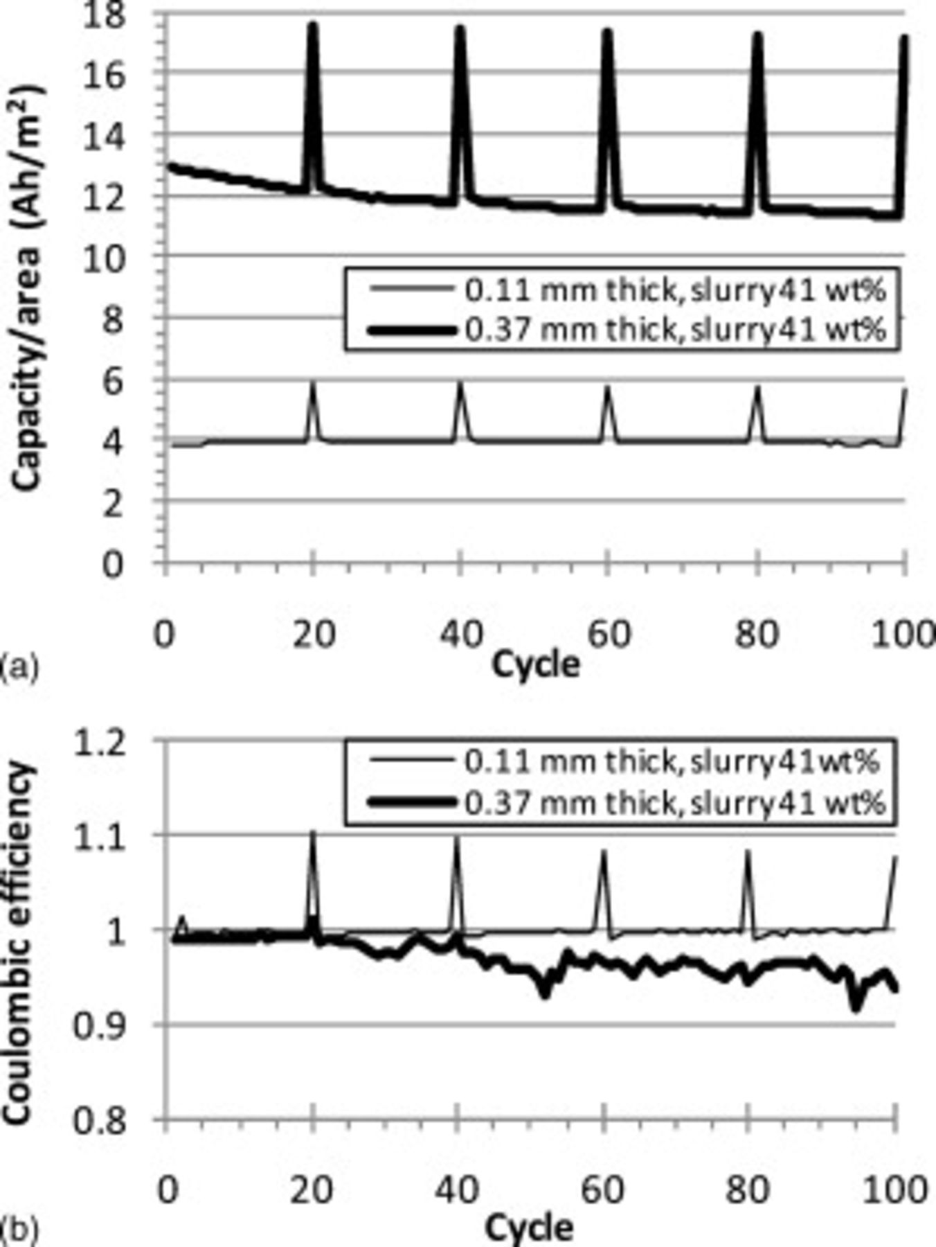
Figure 9. C/2 cycle tests of Swagelok cells with two CFP cathodes made using  slurry: (a) a
  thick CFP and (b) a
  thick CFP cathode. Every 20th cycle was discharged at C/30. The top graph shows the discharge capacity per unit area for these two cathodes and the bottom graph shows the Coulombic efficiency (the ratio of the discharge capacity to the charge capacity).
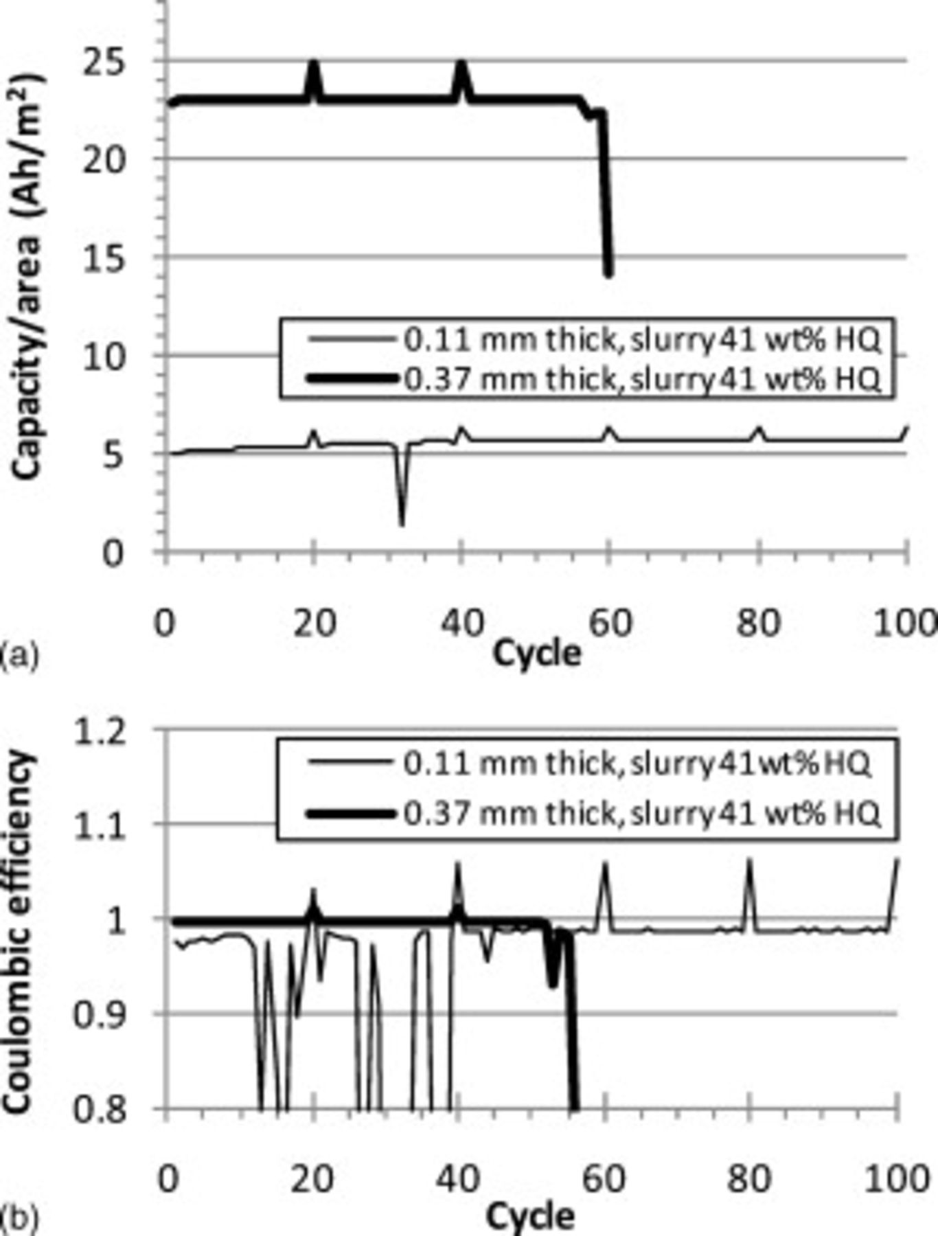
Figure 10. C/2 cycle tests of Swagelok cells with two CFP cathodes made using  HQ slurry: (a) a
  thick CFP and (b) a
  thick CFP cathode. Every 20th cycle was discharged at C/30. The top graph shows the discharge capacity per unit area for these two cathodes and the bottom graph shows the Coulombic efficiency (the ratio of the discharge capacity to the charge capacity).
Discussion
Cathode synthesis was successful. Earlier work surveyed a variety of carbonaceous additives, where AR mesophase pitch was identified as a superior additive for these composites. Lithium iron phosphate particles have been reported to undergo undesirable particle growth at or above  (Ref. 13) and to thermally decompose in the presence of carbon during heat-treatment at elevated temperatures. After primary carbonization of pitch
  ,16 the electrical conductivity of carbonized pitch improves with increasing carbonization temperature as carbonization gases are released and the graphene sheet microstructure becomes more oriented.17 As a compromise, to obtain sufficiently carbonized pitch and to avoid undesirable
  particle growth or decomposition, the carbonization temperature for CFP cathodes was chosen to be
  . The near-theoretical capacity obtained for CFP cathodes with HQ powders, along with SEM and X-ray diffraction, indicated that no significant detrimental particle growth or decomposition of
  occurred.
Battery testing results for CFP cathodes were promising. CFP cathodes with HQ powders had specific energies (up to  ) that begin to approach commercial cathodes for high energy lithium ion cells. Assuming a specific energy density of
  for
for  (Refs. 18, 19) (based on the maximum discharge for practical battery usage) and typical cathode component weights for a
 cell,1, 20 the specific energy density for a complete
  cathode for a commercial
  cell can be estimated to be
  . The slurry loading must be increased in order to increase the specific energy of CFP cathodes. For the
  thick cathode using HQ powder, the weight percent of
  must increase to
  (
( porosity in cathode) to achieve
  . The slurry compositions of CFP cathodes in this study were not optimized, so it is likely that more concentrated slurries or a process including multiple repeated slurry coatings could be utilized which would result in higher specific capacities. In addition, the CFPs were off-the-shelf commercial products. Lower density CFPs could also potentially result in higher specific capacities in CFP cathodes.
To be feasible, several key properties of CFP cathodes must be demonstrated or improved, and cost must be reduced. Improved cycle life and superior thermal management must be demonstrated. Cycling performance was promising, but the large thickness of lithium cycled likely resulted in severe growth of dendritic and porous lithium which prevented a full evaluation of cycle life. Future testing using carbon anodes may be used to better evaluate cycle life. Preliminary thermal testing has been performed which indicated that the thermal diffusivity of a CFP cathode was approximately the same as the underlying CFP support. A preliminary cost comparison between CFP cathodes and commercial cathodes largely boils down to comparing the cost of CFP to aluminum foil, binder, and carbon black. Even though the cathode support or current collector is not the most expensive battery material per unit weight, Toray's CFPs are not cost feasible for commercial production, because they are approximately 1–2 orders of magnitude more expensive than thin aluminum foil.20 The current processing method was chosen for a proof-of-principle of the fundamental cathode structure; alternative processing methods are being considered which should produce equivalent cathode structures with less costly carbon fiber material and higher loading of active powder per unit area.
Conclusion
Lithium ion battery cathodes produced using carbon fiber paper (CFP) supports have been demonstrated. The CFP cathodes using HydroQuebec  powders had excellent discharge curve shape, approximately 100% lithium utilization, and high specific power and energy (when the total cathode weight is considered). The cycling behavior of Swagelok cells with CFP cathodes was inconsistent, likely because of the thick porous and dendritic layer on the lithium anode caused by the cathode's high capacity per unit area. Nonetheless, some cells showed good cycling performance. With their high thermal diffusivity and their potential for excellent cycling behavior, CFP cathodes have potential utility for large-scale lithium ion batteries.
Acknowledgments
The authors acknowledge the high quality SEM work of Karren More and Shawn Reeves (ORNL) and the preliminary thermal property measurements of Hsin Wang (ORNL). Also, the authors thank Karim Zaghib at HydroQuebec for supplying the  powders used in this study. This work was supported by the Assistant Secretary for Energy Efficiency and Renewable Energy, Office of Vehicle Technologies of the U.S. Department of Energy under the Batteries for Advanced Transportation Technologies (BATT) Program. Electron microscopy was conducted at the Shared Research Equipment (SHaRE) user facility (ORNL), which is sponsored by the Division of Scientific User Facilities, U.S. Department of Energy. Oak Ridge National Laboratory is managed by UT-Battelle, LLC, for the U.S. Department of Energy under Contract no. DE-AC05-00OR22725.
Oak Ridge National Laboratory assisted in meeting the publication costs of this article.