
Abstract
Anodic performance and power generating properties of the cell using various oxide composites consisting of Mn, Fe co-doped  and perovskite oxide were investigated by using
  electrolyte. It was found that the theoretical open circuit voltage and reasonably high power density were achieved on the cell using oxide composites consisting of
  for anode. The maximum power density was achieved for values of
  , 0.3, and
  at 1273, 1073, and
  , respectively. Oxidation tolerance was also studied and it was found that the power density was slightly improved after exposure to reoxidation treatment. This study demonstrated that the cell using
  and
and  based oxide composite for anode is highly tolerant against reoxidation treatment. An increase in in the power density by reoxidation treatment was observed and this could be attributed to the improved contact of
  composite powder.
Export citation and abstract BibTeX RIS
Solid oxide fuel cells (SOFCs) are now attracting much attention as one of the most advanced technologies for an environment friendly power generator due to its high energy conversion efficiency and fuel flexibility, and so currently, SOFC is approaching marketability.1–3 However, several unsolved critical issues for commercialization still remain. The most critical disadvantage of the current SOFC is its low reliability against reoxidation and coke deposition. In addition, the operating temperature of SOFC is high  , and so all materials used for the cell should be durable against oxidation at operating temperature and dimensionally stable and resistant to sintering. Therefore, although the operating temperature of the present cell decreases compared to that of the conventional one, a further decrease in operating temperature is desired from material construction, durability, and reliability.
At present, metal Ni based cermet containing an oxide ion conductor such as yttrium stabilized  or Sm doped
  is widely used for anode; however, for the purpose of improved reliability, there are several issues to be overcome, i.e., high tolerance against the coke deposition and reoxidation and high mechanical strength. Since Ni based anode is highly active to an electrochemical oxidation of fuel, Ni has been widely used for anode at an early stage of SOFC development. However, oxidation easily occurs on Ni, resulting in deactivation of the cell.4–6 In particular, in the most serious case, SOFCs will be fractured because of a volume change by reoxidation. For these reasons, the anode with oxidation tolerance is strongly desired from a reliable cell, however highly difficult subjects may be.7, 8 Development of a nickel-free anode such as Cu–ceria base9 and perovskite oxide anode, which is highly tolerant against a redox cycle, has recently attracted great attention. Tao et al. reported that the high power density could be achieved by using
  (Ref. 6, 10) for anode and we also reported
  base oxide anode;11 however, further improvement in anodic performance is still strongly desired.
In this study, we investigated the anodic performance of Mn, Fe co-doped  mixed with various oxides as anode for SOFC using
  base electrolyte. Furthermore, we demonstrated that the relatively high power density could be achieved by using oxide composite anode consisting of
  and
and  for SOFC with oxidation tolerance.
Experimental
Oxides of  and
and  were prepared by using the conventional solid-state reaction method. After dissolving the starting reagents into distilled water at the appropriate ratio, water and nitrate were evaporated and the obtained powder was calcined at
  for
for  in air. The starting reagents used in this study were
  (98%, Kishinda Chemical Co. Ltd., Japan),
  (99.9%, Wako Pure Chemical Co. Ltd., Japan),
  (98%, Wako Pure Chemical Co. Ltd., Japan),
  (99%, Kishinda Chemical Co. Ltd., Japan), and
  (99.9%, Wako Pure Chemical Co. Ltd., Japan). Furthermore, other oxides as anodes were also prepared by using the similar conventional solid-state reaction method at
  . Thus, obtained powder was mixed in
  mortar with
  pestle for
  .
.
The composition of  (LSGMC) was always used for the electrolyte. The self-supporting LSGMC electrolyte disk of which thickness was always fixed as
  was prepared by the tape casting method and final sintering was performed at
  for
for  in air. Details of the preparation method for LSGMC tape casting electrolyte are mentioned elsewhere.12 Perovskite oxide of
  prepared by the solid-state reaction method was used as cathode. The obtained electrode powder was coated on each face of the LSGMC electrolyte with
  diameter for cathode and anode, followed by calcination at
  for
for  . The platinum electrode prepared by using the commercial Pt paste (Tanaka TR7902) was used as the reference electrode, and the reference electrode was put close to the cathode. The platinum lead wire was connected to the Pt reference.
X-ray diffraction (XRD) measurement was performed by using the commercial diffractometer (Rigaku Rint 2500, Japan), and scanning electron microscope (SEM) images were also obtained with commercial SEMs (VE-7800, Keyence Co., Japan). For measuring the electrical conductivity, the powder was pressed into a disk followed by sintering at  and then cut into a rectangular bar shape
  . A Pt electrode was generally used and the electrical conductivity was measured by the dc four-probe method.
Power generating property was measured with four Pt lead lines, and humidified  and
and  were used for fuel and oxidant. The IR loss and overpotential of anode were estimated by using the current interruption method. Property of oxidation tolerance was measured by keeping the temperature at
  because of the removal of the thermal cycle effects. After power density measurement before reoxidation treatment,
  fuel was first purged with
  and then the anode gas was changed to air. After anode was exposed to air at
  for
for  , the air was again changed to
  followed by changing to humidified
  . The power generating measurement after each redox cycle was measured with the same procedure.
Results and Discussion
Power generating property of the cell using oxide composite anode
In our previous study, it was found that Mn and Fe doped  shows reasonably high performance as an anode for SOFC, as shown in Table I.13 Reasonably high power density and small anodic overpotential were achieved on
  (CMF) oxide anode. Figure 1 shows the temperature dependence of the maximum power density and the internal resistance of the cell using CMF anode. Unlike a metal base anode, due to the low electrical conductivity, current collecting effect is not high enough in the case of oxide anode, in particular, at low temperature. Therefore, the power density of the cell using oxide anode shows a much lower effect than that of Ni base anode. For example, the cell using Ni–Fe anode exhibited the maximum power density of
  at
at  ; however, it is only
  in the case of the cell using CMF anode. This decreased power density of the cell using oxide anode is explained by the large IR loss resulting from insufficient conductivity of CMF. Evidently, the potential drop by IR loss of anode was more dominant than that by overpotential in the CMF anode, as shown in Fig. 1. However, anodic overpotential still sustains a small value at a decreased temperature such as
  . This suggests that the sufficient surface activity of this oxide for anodic reaction was exhibited at an intermediate temperature range. Although power density of the cell using CMF is still lower than that of Ni, an increase in power density could be expected with an increase in the electrical conductivity of anode. In this study, effects of mixing conductive oxide with CMF are studied for improving the power density at intermediate temperature.
Table I. Power density and anodic properties of single cell using various oxide composites anodes at  .
.
| Oxide anode for SOFC | At 
| |||
|---|---|---|---|---|
| Cell performance | Potential drop (mV) | |||
| OCV (V) | MPD
|

|

| |
| 1.056 | 330 | 5 | 45 |
| 1.066 | 235 | 56 | 136 |
| 0.993 | 46 | 59 | 181 |
 
| 1.113 | 315 | 36 | 95 |
 
| 1.082 | 204 | 157 | 325 |
 
| 1.086 | 46 | 563 | 765 |
 
| 1.084 | 49 | 334 | 593 |
 
| 1.079 | 59 | 49 | 162 |
 
| 1.092 | 1.2 | — | — |
 
| 1.108 | 23 | 153 | 427 |
 
| 1.109 | 242.3 | 44 | — |
 
| 1.103 | 170.77 | — | — |
 
| 1.117 | 254 | 38.4 | 168 |
aPotential drop at  , cathode;
  , electrolyte;
  . bPotential drop at
  .
. ; anodic overpotential,
  ; anodic resistance loss.
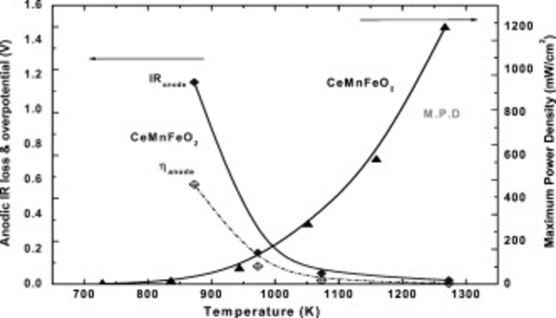
Figure 1. Temperature dependence of anodic overpotential, IR loss, and maximum power density of the cell using  for anode. (IR loss and η of anode was at
  ); (▲) MPD, (◆) anodic overpotential, (◆) IR loss.
Table I shows the power generating property and internal resistance of the cell using various composite oxides at 1073 and  . Mixing effects of oxides with high electrical conductivity were mainly studied. Evidently, power generation property as well as internal resistance of the CMF anode were strongly affected by oxide combined. In the case of
  ,
,  , or
, or  , internal resistance of the cell was much improved, resulting in the small power density. On the other hand, mixing
  , which is reported as a promising oxide anode,6 with CMF shows rather high power density; however, anodic overpotential is large and this may suggest the low activity of this composite to anodic reaction. Among the examined oxides, the composite using
  (LSFM), which is reported as another candidate for oxide anode, shows reasonably small anodic overpotential and IR loss at high temperature and also at
  . Comparing anodic properties of LSFM with those of CMF, IR loss and overpotential of LSFM at a decreased temperature range were smaller than those of CMF. Therefore, oxide composite of CMF and LSFM exhibited improved cell performance at a decreased temperature because of high conductivity of LSFM. Consequently, at
  , the cell using composite oxide anode consisting of LSFM and CMF exhibited higher power density, and so in this study, anodic performance of oxide composite of LSFM–CMF was studied in detail.
Figure 2 shows the maximum power density of the cell using CMF–LSFM composite anode as a function of CMF content. Obviously, the power density was strongly dependent on the composition of CMF and LSFM composite, and the highest power density at a temperature lower than  was achieved on the composition at
  ratio. On the other hand, the maximum power density of the cell using anode with CMF-rich composition at high temperature region was much higher and the highest power density at
  was achieved when
  CMF was mixed with LSFM. This complicated dependence of the power density on the composition can be explained by the high surface activity of CMF and the electrical conductivity of LSFM. Namely, CMF shows the high activity for anode reaction; however, because of low conductivity at intermediate temperature, the decrease in power density is significant. On the other hand, the electrical conductivity of LSFM is high; however, because of low surface activity for anodic reaction at intermediate temperature, the high power density at intermediate temperature can be achieved by mixing CMF with LSFM. In any case, the appropriate amount of CMF in oxide composite is different depending on the operating temperature. The objective of this study is to increase the power density at decreased temperature range because of a variety of materials and low durability of the cell performance. Therefore, a further detailed study was performed on
  LSFM–
LSFM– CMF anode. For this composition, the maximum power density at
  is
is  , which is relatively high considering the power density of
  of the cell using Ni–Fe metal anode.
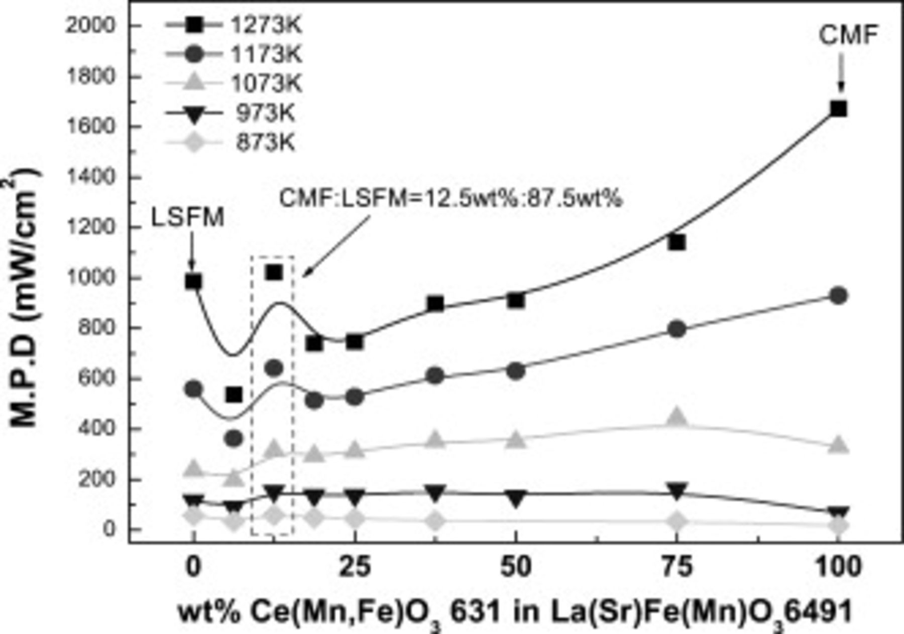
Figure 2. Maximum power density of the cell using CMF-LSFM composite anode as a function of CMF amount in composite anode.
Figure 3 shows the electrical conductivity of LSFM, CMF, and CMF–LSFM oxide composite  oxide in air and
  . In air, as shown in Fig. 3, electrical conductivity of LSFM is much higher than that of CMF and the oxide composite shows slightly lower conductivity than that of LSFM. The electrical conductivity of LSFM is close to
  and a metal-like temperature dependence is observed. Therefore, as discussed, mixing LSFM with CMF is effective for increasing the electrical conductivity. On the other hand, in
  atmosphere, electrical conductivity of LSFM decreases significantly because of dominant hole conduction14–16 and temperature dependence is semiconductor one. In contrast to LSFM, the conductivity of CMF greatly increases in
  atmosphere because of partial electronic conduction; however, it is still small at intermediate temperature. Obviously, composite oxide shows a similar electrical conductivity with LSFM and the conductivity is always higher than
  , which is still lower than that desired for electrode; however, the electrical conductivity of CMF can be much improved by mixing with LSFM.
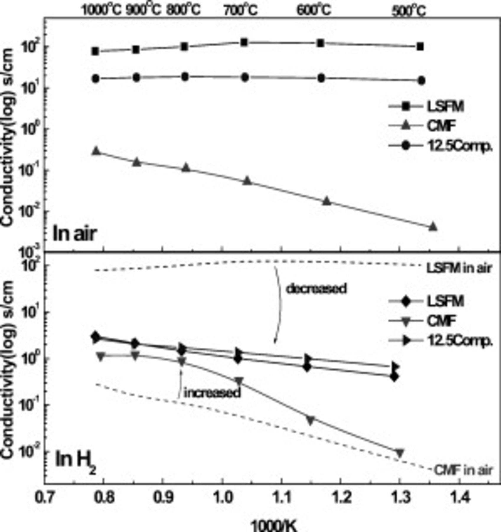
Figure 3. Electrical conductivity of CMF, LSFM and  CMF-LSFM composite oxide in air and
  as elevated temperature to
  ; electrical conductivity of LSFM in air (◼), LSFM in
  (◆), CMF in air (▲), CMF in
  (▼),
(▼),  CMF and LSFM composite in air (●) and in
  (▶).
(▶).
Figure 4 shows I–V and I–P curves on the cell using  CMF–LSFM composite oxide anode. The cell using this optimized composite oxide for anode exhibits the maximum power density of 1000 and
  at 1273 and
  , respectively. Therefore, although power density is still smaller than that of the Ni–Fe anode cell, the LSGMC cell using CMF–LSFM composite anode shows a reasonably high power density at intermediate temperature and at
  , the observed power density is similar to that of Ni base metal anode. Therefore, mixed oxide of
  CMF–LSFM is promising as an oxide anode for intermediate temperature SOFCs.
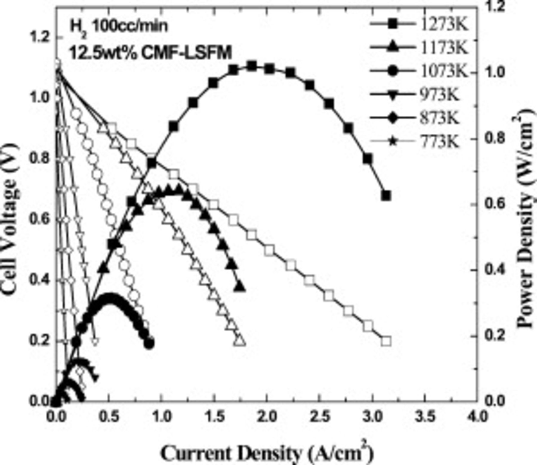
Figure 4. Power generating property of the cell using oxide composite consisting of  and
and  with optimized synthesized oxide composite of
  CMF and LSFM.
Figure 5 shows the details of the internal resistance of the cell at 1073 and  . Anodic IR loss and overpotential are still large; however, fairly high power density can be achieved on the cell. Obviously, potential drop by IR loss was more significant than that by overpotential at anode site, as shown in Fig. 5. Therefore, increase in power density could be expected as the electrical conductivity of CMF–LSFM composite increases, and this is now under study.
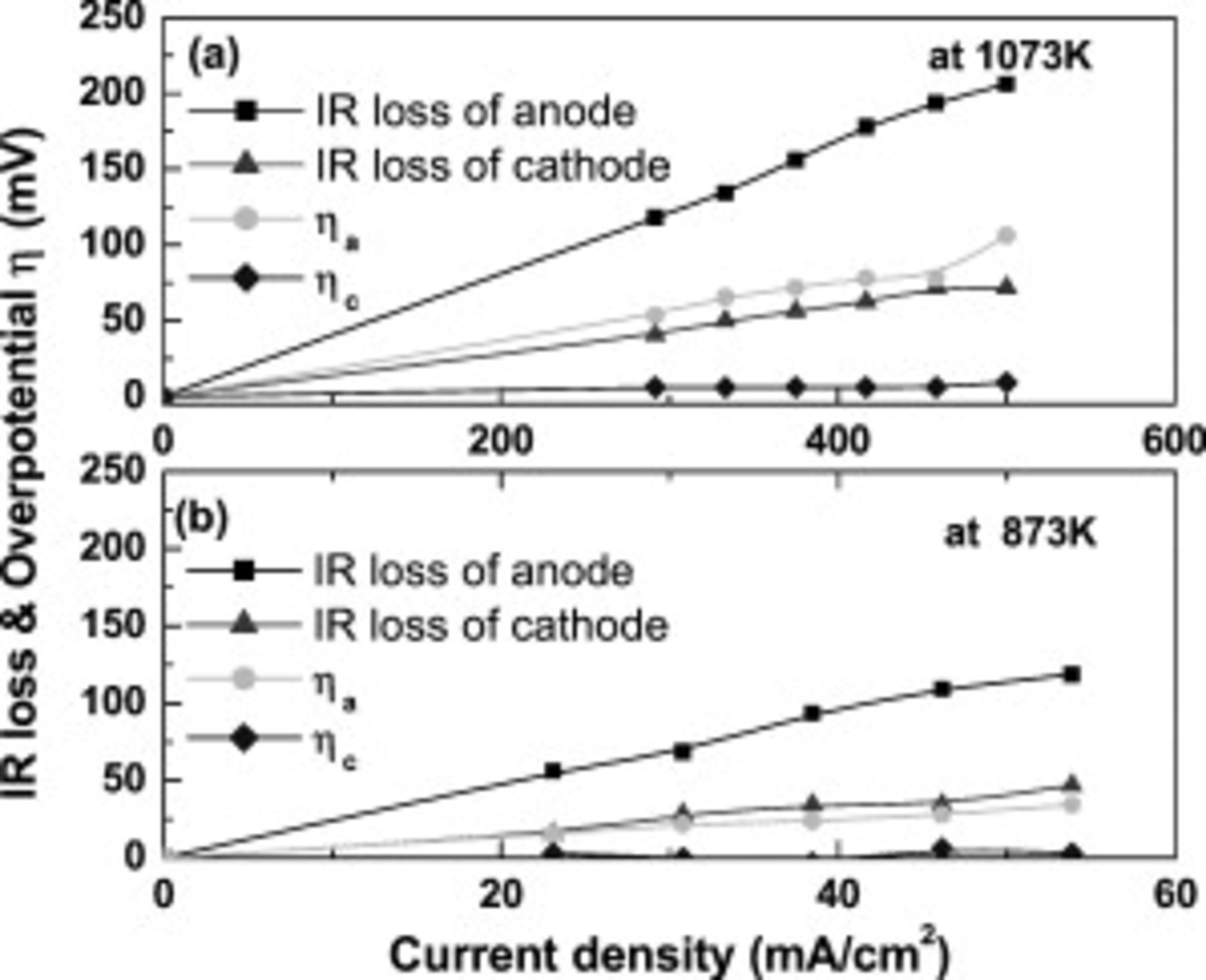
Figure 5. Internal resistance, IR loss, and overpotential of anode and cathode as a function of current density.  CMF and LSFM composite is used as anode and operating temperature is (a)
  and (b)
  in
in  .
.
Figures 6 and 7 show the phase stability of composite anode during operation and calcination of anode. According to XRD patterns after power generation measurements (Fig. 6), the oxide state of CMF and LSFM is confirmed. These XRD patterns indicate that the major peaks were assigned to those of  ,
,  , and LSGMC electrolyte before and after the power generation measurement. There are no XRD peaks assigned to a secondary phase and so there is no reaction between CMF and LSFM under the operating condition at
  . Furthermore, XRD measurement on CMF–LSFM composite was performed for further analysis of the reaction between CMF and LSFM. Composite oxide of CMF and LSFM was calcined at each temperature for
  and then XRD measurement was performed as shown in Fig. 7. There is also no secondary phase observed by XRD up to
  and it seems that reactivity of CMF and LSFM is low and no secondary phase seems to be formed during calcination of anode. Thus, the oxide state of both CMF and LSFM seems to be stable in
  atmosphere and no reaction with LSGMC electrolyte is also confirmed.
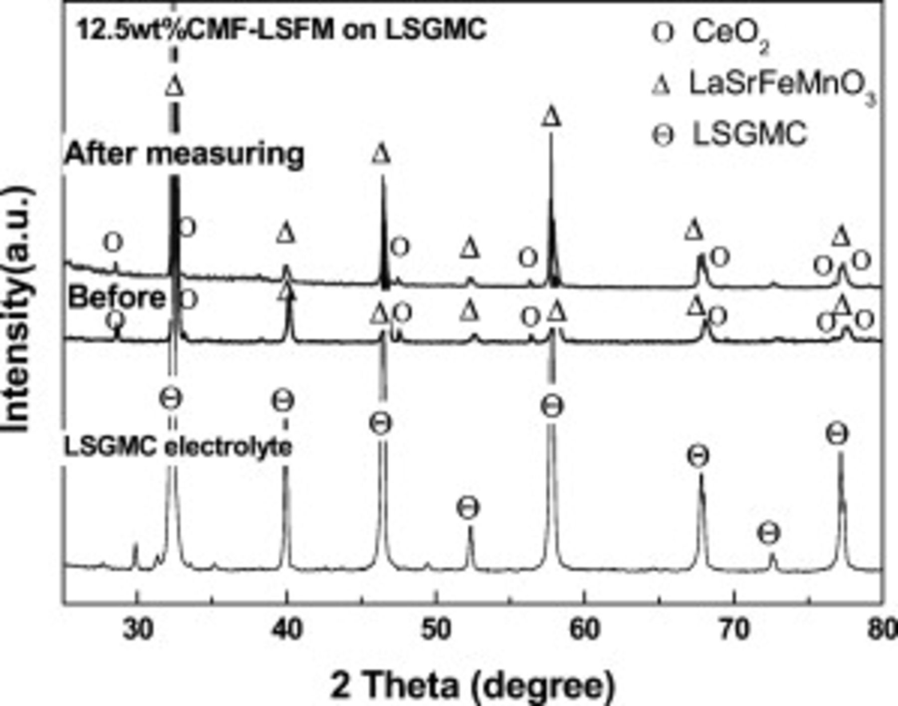
Figure 6. XRD pattern of  CMF-LSFM on LSGMC electrolyte after power generating measurements.
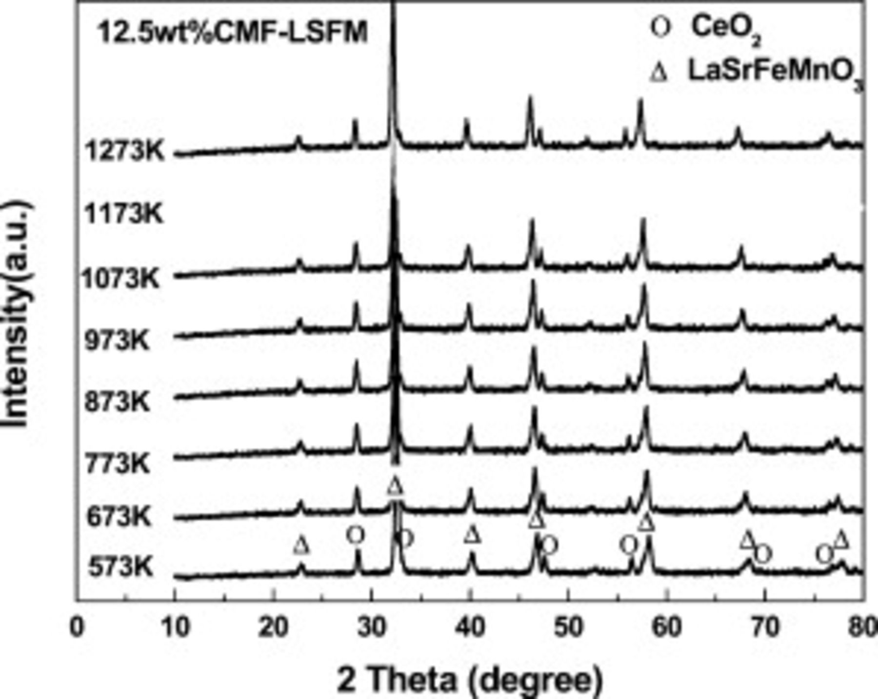
Figure 7. XRD pattern of  CMF-LSFM composite mixed powder with elevated temperature up to
  .
.
Reoxidation tolerance of CMF–LSFM oxide anode
An advantage of oxide anode is the tolerance against the reoxidation. Thus, oxidation tolerance of the oxide anode,  –LSFM composite, was examined in this study. Since we focused on the intermediate temperature operation, reoxidation effects were measured at
  . Figure 8 shows the I–V and I–P curves for CMF–LSFM systems after the reoxidation treatment at
  . The cell used for the reoxidation tolerance measurement is different from that used for the temperature dependence one (Fig. 4) and so slightly smaller power density was observed before a reoxidation treatment. The difference in the power density in Fig. 4 and 8 may come from the different history of reduction temperature. The cell in Fig. 4 was exposed to
  at 1273 and
  before measurement at
  . However, the cell in Fig. 8 is exposed to
  only at
  . As discussed, main internal resistance of the cell is IR loss at the anode aide, which could be assigned to the low electrical conductivity of CMF–LSFM. The reduced state of CMF–LSFM composite oxide may be varied with the reduction temperature. Therefore, the power density in Fig. 4 at
  seems to be slightly higher than that in Fig. 8. When Ni is used for anode, the cell was permanently damaged after reoxidation treatment. In contrast to Ni cermet anode, evidently, the power density of the cell did not decrease, but slightly increased by oxidation treatment, when oxide composite of CMF–LSFM was used for anode. This might be explained by not only improved contact between the composite anode and electrolyte but also improved surface reactivity of CMF–LSFM by improvement in the amount of oxygen vacancy with redox reaction treatment. Another reason is to improve the electrical conductivity by reoxidation treatment because the conductivity in the oxidation state is higher than that of the reduced one (Fig. 3). In any case, it is evident that the CMF–LSFM anode is promising as the anode for SOFC with oxidation tolerance and this is the most significant advantage of all ceramic cells. Improved mechanism of CMF–LSFM composite oxide is studied in further detail.
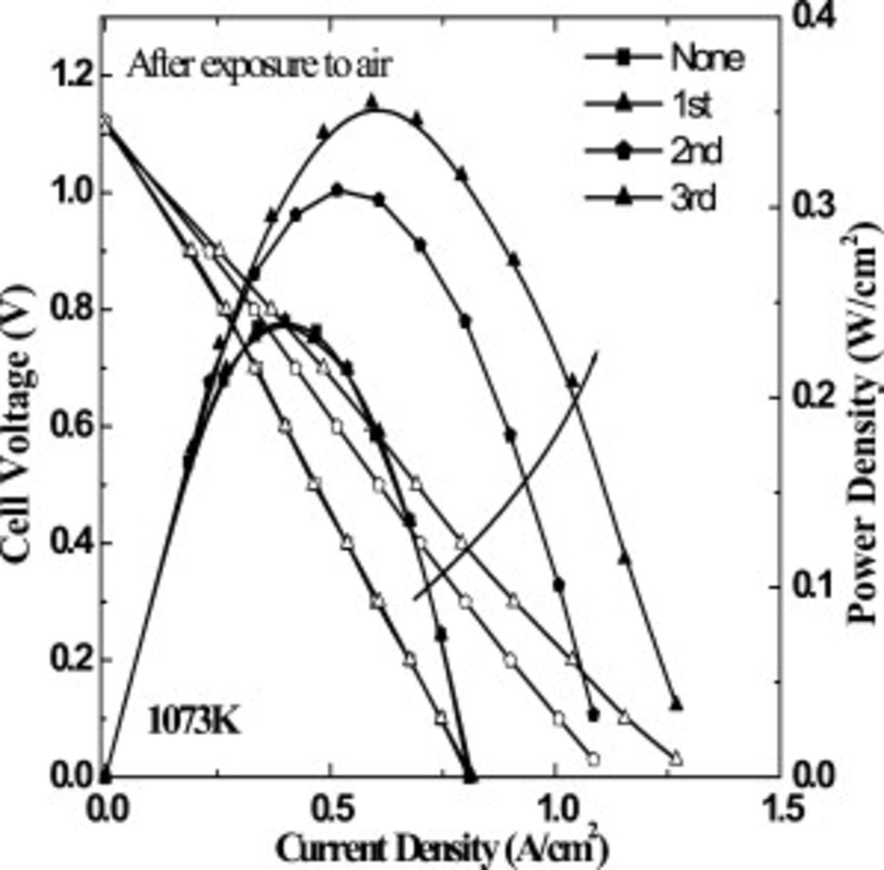
Figure 8. Power generating property of the cell using oxide composite consisting of  CMF-LSFM as anode for SOFC after exposure to air at
  (redox cycle).
The reason for the power density increase with reoxidation times was further studied by using an impedance measurement of anode reaction. Figure 9 shows the complex impedance plots of anode before and after reoxidation treatment at open circuit condition. In order to assign the impedance plots to anode process, further detailed experiments are required; however, in this study, two semicircles at the high and low frequencies were roughly assigned to the surface reuction (activated overpotential) and gas diffusion (concentration overpotential) resistance from frequency. Obviously, semicircle at lower frequency, which could be assigned to the gas diffusion resistance, is hardly changed or slightly increased by reoxidation treatment. On the other hand, semicircle at higher frequency, which could be assigned to the surface reaction resistance, was greatly decreased by reoxidation treatment. Therefore, one reason for the decreased internal resistance could be attributed to the decreased anodic overpotential, in particular, activation overpotential, because of expanding the effective reaction area as discussed later. It is also noted that the resistance estimated by x-axis intercept at higher frequency is also slightly decreased by the reoxidation treatment. Therefore, decrease in IR loss is also another reason for the improved power density. However, because of values changed, it seems that the improvement in power density of the cell could be mainly attributed to that of the surface activity of CMF–LSFM oxide anode. There are two reasons considered for decreasing activation overpotential: one is the formation of a compound which is active to the anode reaction during reoxidation treatment and the other is powdering of CMF–LSFM oxide by a volume change of redox treatment.
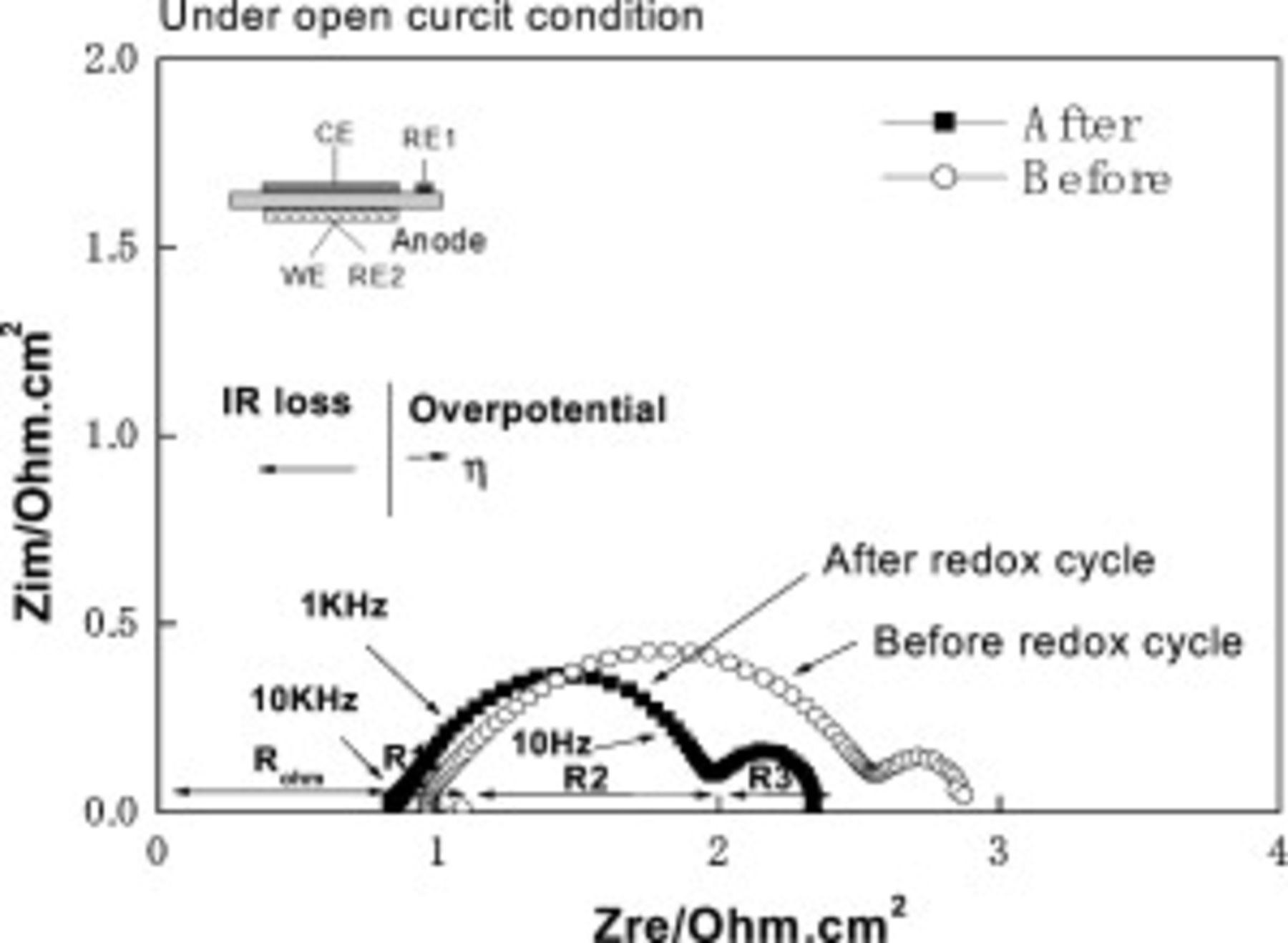
Figure 9. Impedance spectra of the cell using oxide composite consisting of CMF-LSFM as an anode for SOFC after and before exposure to air for  at
at  (with redox cycle).
In order to confirm the decomposition of the crystal phase of CMF and LSFM after reoxidation treatment, XRD measurement was performed after reoxidation measurement. Figure 10 shows XRD patterns of the CMF–LSFM anode on LSGMC electrolyte before and after power generating measurement under operation conditions with the reoxidation treatment. Since the disk was broken into small pieces after measurement, the diffraction peaks decreased in peak intensity and broadened. XRD patterns after reoxidation treatment are the same as those before treatment. Therefore, it seems that no secondary phase, which is formed by phase separation, was observed during the reoxidation treatment, and this may suggest that chemical stability of CMF with LSFM under changing oxygen partial pressure seems to be high. As a result, CMF–LSFM composite oxide did not form secondary phase or decomposition phase and so decreased activation overpotential by reoxidation treatment is not attributed to the new phase formed during reoxidation treatment. Considering the low temperature,  , for reoxidation treatment, it is reasonable that no decomposition phase, which improves the anodic performance of CMF–LSFM, is formed.
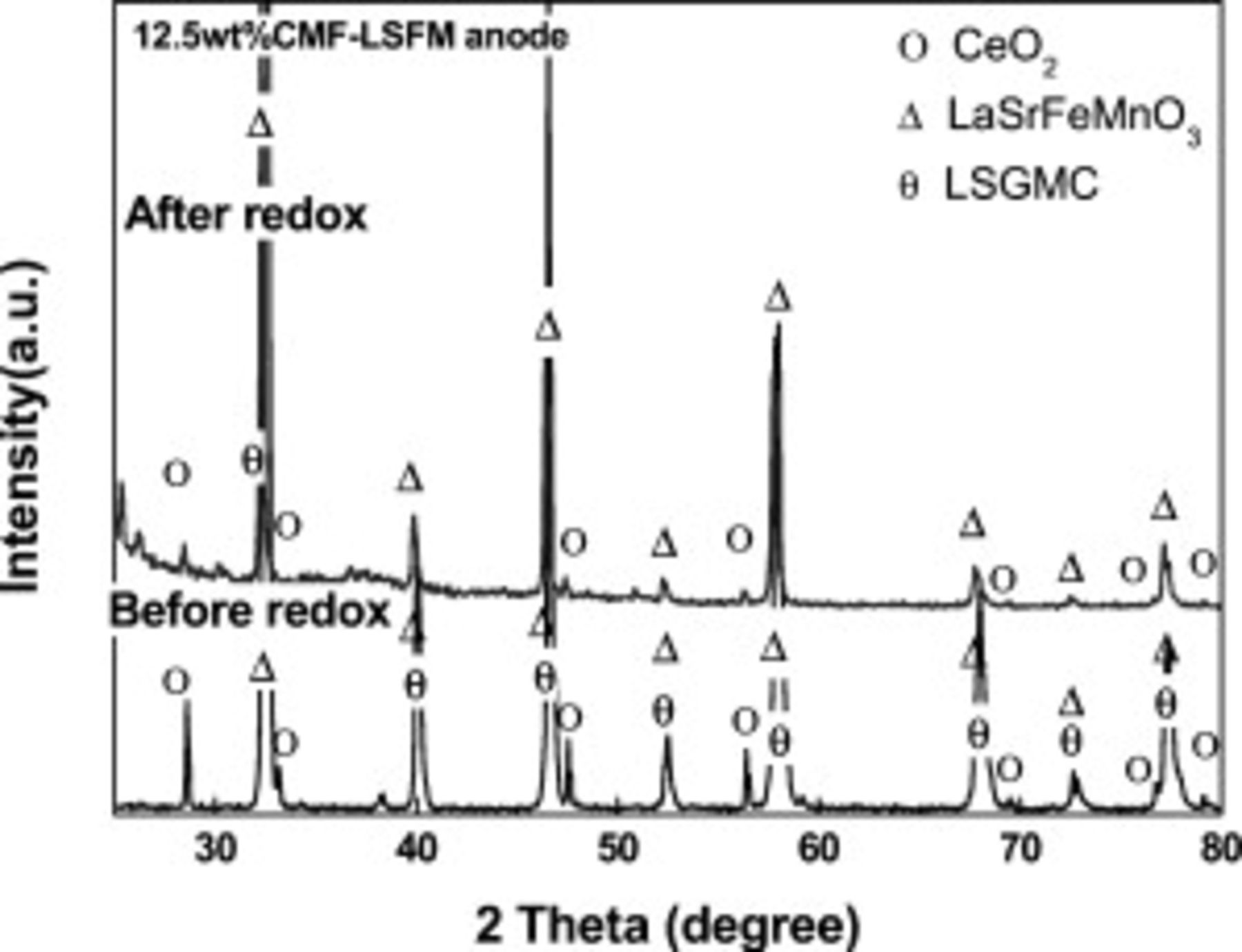
Figure 10. XRD pattern of  CMF-LSFM composite anode on LSGMC electrolyte before and after reoxidation treatment.
Since it is generally known that reduction leads to the volume expansion, large volume change is reasonably expected for CMF–LSFM oxide composite during reoxidation and reduction treatment. In the case of  or
or  , it was also reported that the oxide anode was powdered by redox cycle.17–19 The morphologic modification of the anode surface with redox cycle would suggest a change in lattice volume caused by a mixed valence state of Mn and Fe. Therefore, a similar broken surface of oxide anode of CMF–LSFM is also expected. Change in the microstructure of
  CMF–LSFM oxide composite was also studied, and Fig. 11 shows SEM observation results of CMF–LSFM electrode before and after reoxidation treatment. Evidently, particle size of CMF–LSFM powder was decreased by reoxidation treatment. Because the IR loss slightly decreased, delamination of oxide anode seems not to occur. It seems that contact area can be expanded by powdering of LSFM–CMF composite anode after reoxidation treatment. It is considered that the length of the three phase boundary is much enlarged by reoxidation treatment, and this also improves the contact between anode and electrolyte, resulting in the decreased IR loss. Therefore, this study shows that the improved power density of the cell using CMF–LSFM anode after reoxidation can be assigned to the powdering of anode oxide. In any case, obviously, CMF–LSFM is highly active to the anode reaction and also stable against reoxidation. Consequently, CMF–LSFM oxide composite is a promising oxide anode with high tolerance against reoxidation.
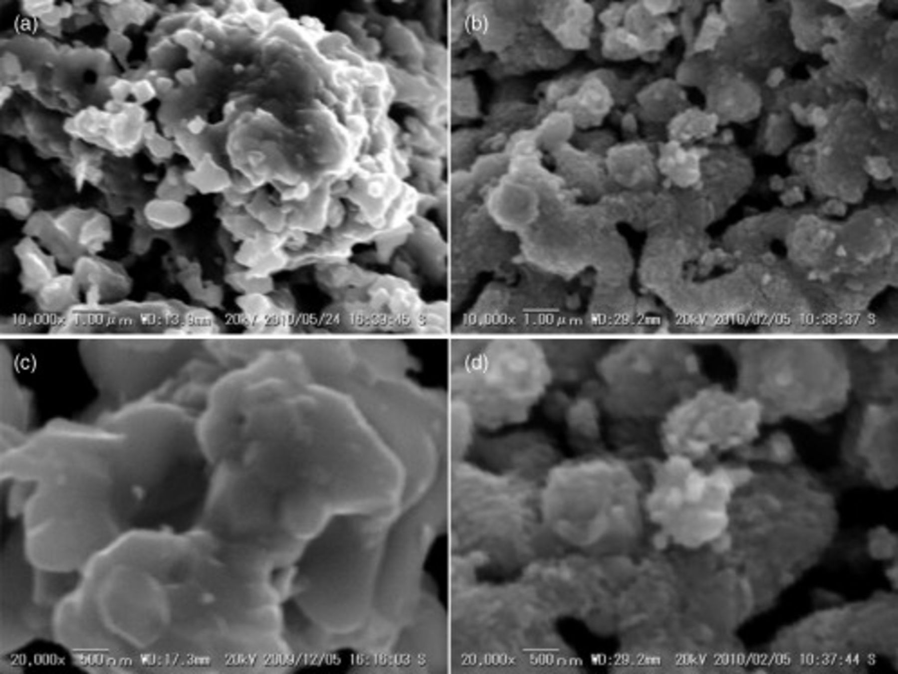
Figure 11. SEM images of  CMF-LSFM composite anode before and after redox cycle; (a) cross section, (c) before redox cycle, and (b), (d) after cell operating with third reoxidation cycle, (a), (b) low-magnification and (c), (d) high magnification SEM images.
Conclusion
Up until now, the most important subject for SOFCs is an increase in reliability as power generator. For this purpose, the development of oxide anode that is tolerant against carbon deposition, reoxidation, and sulfur poisoning is strongly required. There are several oxides reported for oxide anode; however, the power density of the reported oxide anode at intermediate temperature is small because of the insufficient electrical conductivity as well as surface activity. In this study, it was found that a relatively good power generation property of the cell was achieved at intermediate temperature by using oxide composite consisting of  and
and  . In particular, theoretical open circuit voltage (OCV) and high power density were achieved on the cell using
 for anode. The maximum power density was achieved for values around 1 and
  at 1273 and
  , respectively. Moreover, this study demonstrated that the cell using CMF–LSFM is highly tolerant against reoxidation. This is the most significant future of oxide anode. Compatibility in thermal and chemical expansion of the anode with that in LSGMC electrolyte is also desired. However, this is now under study and the results will be reported in the future with oxygen nonstoichiometry of CMF–LSFM composite. Consequently, this study reveals that mixed oxide of
  is highly promising as the oxide anode for intermediate temperature SOFC.
Kyushu University assisted in meeting the publication costs of this article.