
Abstract
Zinc-air batteries were fabricated using porous zinc anodes with various concentrations of Super P carbon black additive. The introduction of Super P significantly improved the electrochemical performance of the batteries. The specific discharge capacity and power density of the Zn anode with 2 wt% Super P anode was 776 mA h g−1 and 20 mW cm−2, respectively. The batteries also exhibited good durability and stability at an open circuit voltage maintained at approximately 1.4 V. The bridging between Zn powders by Super P may explain the improved electrochemical performance of the batteries. Morphological images and structural properties were also analyzed to support these observations.
Export citation and abstract BibTeX RIS
Porous zinc (Zn) anode is a well known materials for zinc-air battery systems.1,2 The products obtained from this method have a high surface area, which is advantageous for better contact of the Zn powder and the electrolyte. However, the passivation of Zn-active materials by Zn oxide (ZnO) during the discharge limits the usage efficiency of Zn.3,4 The use of additives in the porous Zn anode has been proposed in several studies to overcome this problem.5–8 In the selection of the additive material, the requirements that should be taken into account include enhancement of the network at low additive concentration, excellent inter-particle contact, electrolyte access optimization, and inert materials.
Hilder et al.9 have shown that the network in Zn-air batteries is dependent on carbon content because carbon functions as a conductive link between isolated metal particles. Hence, the anode is activated for the electrochemical reaction. Othman et al.8 investigated the addition of particulate graphite into a porous Zn anode system. Nevertheless, the graphite additive blocks the Zn powder and prevents the electrolyte to react in the system. When the graphite content was increased beyond 10%, the battery capacity dropped and remained slightly constant. Braam et al.10 successfully used acetylene black as a conductive additive to decrease the internal resistance of the electrodes, to suppress hydrogen evolution, and to boost active material utilization.
Super P carbon black is a well-known conductive additive for battery applications and is supplied and manufactured by TIMCAL Graphite & Carbon. Based on the characterizations made by Polomores et al.,11 Super P is classified as a furnace black type. The key characteristics of Super P are high purity, large surface area, and structured body with a high void volume caused by the spaces between the carbon black particles.
Gnanamuthu and Lee12 and Gangulibabu et al.13 have proven that commercially available Super P has advantageous effects on lithium-ion battery performance. The boost in the battery performance is due to the combination of electrode materials with Super P, which increases the network and provides continuous discharge performance. Super P offers stable dispersions and binder compatibility, which is suitable for porous anode preparation.
This present study focused on the effects of the addition of Super P to the porous Zn anode on the performance of Zn-air batteries. The porous Zn anode was prepared by mixing Super P and Zn powder in an agar binder paste. The performance of the porous Zn anode was characterized by electrochemical investigations and supported by morphological and structural studies.
Experimental
Preparation of anode and Zn-air battery fabrication
Zn anode paste was prepared by mixing Zn powder (particle size <45 μm, Merck), various percentages of conductive Super P powder (specific surface area of 62 m2 g−1, TIMCAL Graphite & Carbon), and pure agar binder paste (4 mL). All of these main materials were mixed using mortar and pestle. The Zn anode paste was then filled on an nickel (Ni) mesh with an active area of 12.6 cm2 and left to dry at room temperature. The compositions of Zn powder and Super P are shown in Table I. The detailed preparation of the Zn anode paste was explained in a previous report.14
Table I. Composition of anode materials.
| Sample name | Zinc Powder (g) | Super P (g) | Super P (%) |
|---|---|---|---|
| Zn pure | 4.500 | 0 | 0 |
| Zn1C | 4.455 | 0.045 | 1 |
| Zn2C | 4.410 | 0.090 | 2 |
| Zn3C | 4.365 | 0.135 | 3 |
| Zn4C | 4.320 | 0.180 | 4 |
The cathode used was a commercially available MnOx-based air cathode (MEET Co. Ltd, Korea) with an active area of 12.6 cm2. The electrolyte used was a Sago-6 M KOH gel electrolyte. The ratio of Sago:water was set at 1:20 to make the paste, which was then mixed with 20 mL of 6 M KOH to produce optimum properties of polymer gel electrolytes.15 All of the elements were assembled to fabricate a Zn-air battery.
Electrochemical characterization
The discharge performances of Zn-air batteries were characterized at 25°C using Arbin Instrument-BT 2000. The batteries were discharged at a constant current of 100 mA (or 7.9 mA cm−2 with respect to the Zn anode area) at room temperature. The specific discharge capacities of the cells were calculated based on the mass of the added Zn powder. The Zn-air batteries were discharged at various current ranges to obtain the plot of the current-voltage (I-V) and current-power density (J-P) curves by using a general-purpose electrochemical system module (Autolab PGSTAT 30). The fabricated Zn-air batteries were left for approximately 10 min to attain a steady voltage prior to testing. The open circuit voltage (Voc) of the Zn-air battery performance was determined using a Neware battery testing unit in conjunction with the BTS Test Control V5.1 software.
Characterization of anode
The morphological study of the anodes was carried out by field emission scanning electron microscopy (FESEM, Zeiss Supra 35VP). Samples were observed at 30 kV in the secondary electron mode. Furthermore, a transmission electron microscopy (TEM) study was conducted using Philips 420T TEM operated at 120 kV with tungsten filament as an electron source and a spatial resolution of 0.4 nm. The structural studies were performed by X-ray diffraction (XRD, Bruker Advanced-D8). The operation was conducted using Cu-Kα radiation with a wavelength of 0.154 nm. The samples were scanned over a range of 2θ = 20° to 90° with step size of 0.02°. The crystalline phase was identified using the International Center of Diffraction Data (ICDD) powder diffraction database.
Results and Discussion
Discharge performance
Figure 1 shows the discharge characteristics of Zn-air batteries. The use of pure Zn as an anode shows a typical pattern of Zn-air batteries. The overall discharge curves for Zn-air batteries, even after the introduction of Super P in the porous Zn anode, have an L-shape pattern that is characteristic of the discharge behavior of Zn-air batteries. Furthermore, the introduction of Super P in the porous Zn anode enhanced the specific discharge capacity. However, the specific discharge capacity decreased at higher Super P concentrations.
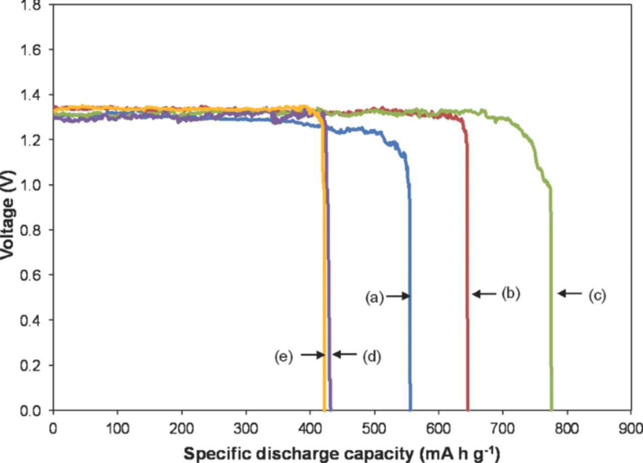
Figure 1. Discharge profile of Zn-air batteries at a constant current of 100 mA as a function of Super P concentration: (a) pure Zn, (b) Zn1C, (c) Zn2C, (d) Zn3C, and (e) Zn4C.
The specific discharge capacity of pure Zn is 556 mA h g−1. When 1 wt% Super P (Zn1C) was added to the anode system, the specific discharge capacity increased to 645 mA h g−1. The highest specific discharge capacity (776 mA h g−1) was achieved at 2 wt% Super P (Zn2C). However, beyond 2 wt% Super P (Zn3C and Zn4C), the specific discharge capacity was reduced to 429 and 422 mA h g−1, respectively.
Compared with the theoretical specific discharge capacity of a Zn-air battery, which is 820 mA h g−1,3,16 the efficiency of the pure Zn obtained was only 68%. The inclusion of Super P enabled the efficiency to increase to 95% for the Zn2C anode. This efficiency is close to the theoretical specific discharge value and is in line with a previous report where batteries commonly have very low standby losses and can have high energy efficiencies ranging from 60% to 95%.3
The average discharge voltage is approximately 1.3 V for all batteries. However, small voltage fluctuations attributed to the porosity of the Zn anode system were observed. This phenomenon can be explained by the inter-granular diffusion reaction of the electrolyte throughout the non-uniform Zn particle compared with the planar Zn anode system.17
Power–current density performance
The I-V and J-P curves were obtained to evaluate further the performances of the Zn-air batteries. Figure 2 shows the behavior of the I-V and J-P curves with the added Super P in the porous Zn anode. The I-V curves (Figure 2a) indicate that the electrode polarizations were dominated by ohmic contribution. The calculated internal resistance (r) of the Zn-air battery was 0.02 Ω for pure Zn powder. The lowest r achieved was 0.01 Ω for the Zn2C anode. However, r also increased with increasing amounts of Super P up to 2 wt%. The r values of Zn3C and Zn4C were 0.03 and 0.05 Ω, respectively.
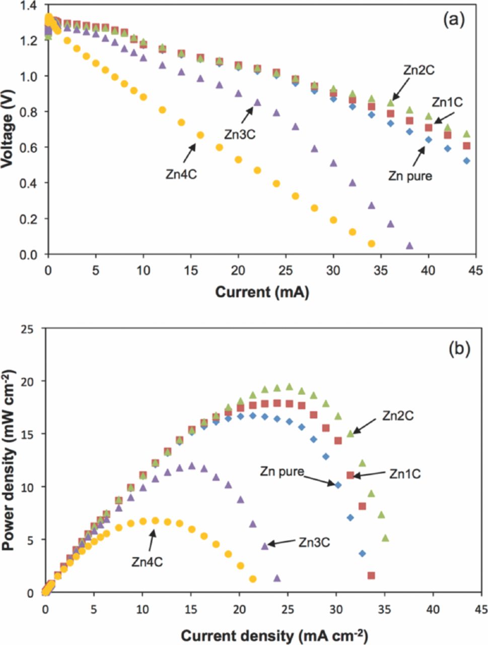
Figure 2. (a) I-V and (b) J-P curves of the Zn-air batteries at different Super P concentrations.
Figure 2b shows the J-P curves. The pure Zn powder generated a maximum power density of 17 mW cm−2 and increased to 18 mW cm−2 when 1 wt% Super P was added. The power density of the anode system with Super P was higher than the pure Zn anode. The maximum power density was 20 mW cm−2 with the Zn2C anode as reference. Thus, the power density for the Zn-air battery with the Zn3C anode decreased to 12 mW cm−2. The lowest performance obtained for the Zn-air battery was observed in Zn4C, which only produced a power density of 7 mW cm−2. The voltage of the battery dropped to a short circuit current density (Jsc) of 33 mA cm−2 for the provenience anode. The value dropped to around 10 mA cm−2 when more than 2 wt% Super P was added. The lowest Jsc was observed in Zn4C at 22 mA cm−2. The highest power density in the present study was comparable with the result of Han et al.,18 who obtained the highest power density of 34 mW cm−2. However, the higher power density was attributed to higher temperature (35°C), the application of an Ag/C-based air cathode, the flow of the electrolyte, and the replaceable Zn powder anode.
Open circuit potential performance
Figure 3 shows the Voc of the batteries by using various concentrations of Super P in the porous Zn anode. The Voc of the batteries had values between 1.3 and 1.4 V. The value was typical for Zn-air batteries with a porous anode.19,20 The small voltage fluctuation was related to the porous characteristic of the Zn anode.8,14
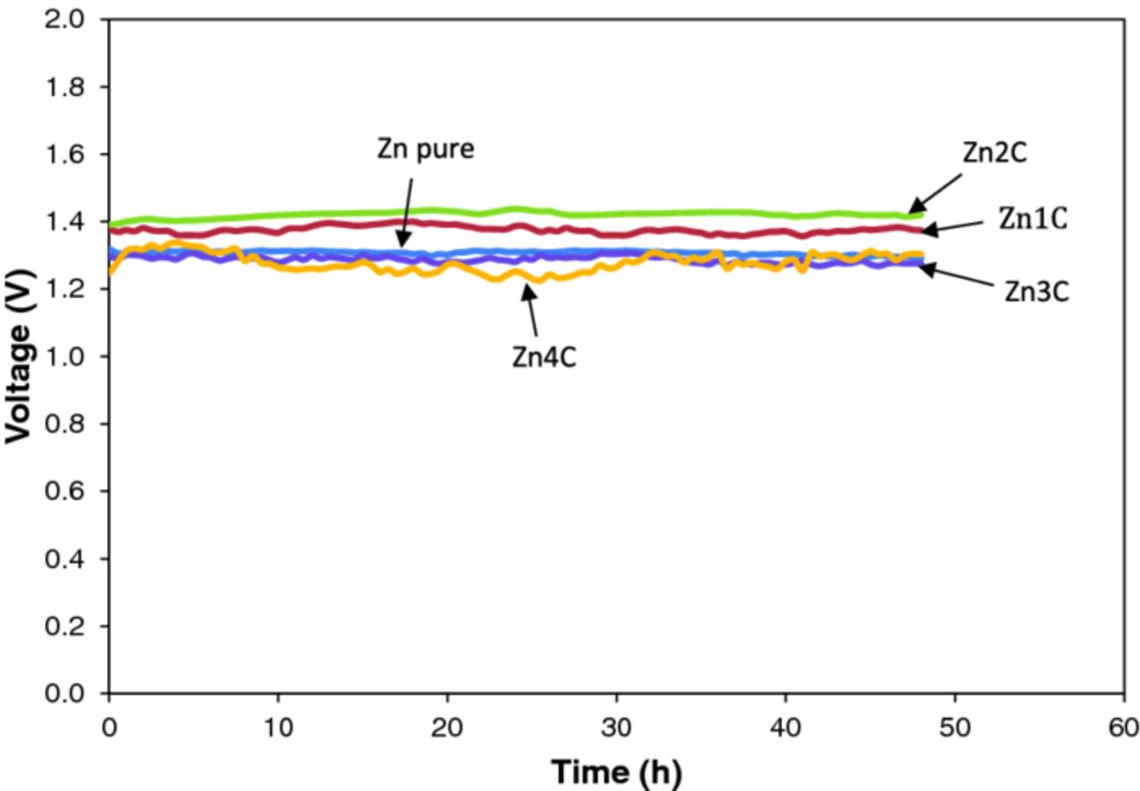
Figure 3. Open circuit potential of Zn-air batteries with various compositions of Super P in the porous Zn anode: (a) pure Zn, (b) Zn1C, (c) Zn2C, (d) Zn3C, and (e) Zn4C.
Pure Zn powder exhibited a Voc of 1.3 V. On the other hand, the Zn-air battery with the Zn1C and Zn2C anodes slightly enhanced the highest Voc to 1.4 V. The Zn-air batteries did not demonstrate any significant voltage loss or self-degradation behavior at Super P contents of 1 and 2 wt% until the end of the storage period at 48 h. These Voc profiles confirm that the Zn-air battery was able to sustain long storage. At higher Super P loading (Zn3C and Zn4C), Voc showed a reduced fluctuation.
Morphology analysis
Morphology studies of raw materials were performed to understand further the effect of Super P on the porous Zn anode. Figure 4 shows the morphology of the raw materials used in the anode preparation. The morphology of dried pure agar binder is shown in Figure 4a. The agar binder surface was inhomogeneous when dried for 7 d. Figure 4b reveals the rough surface of the Zn powder. For the dried porous anode, the combination of the Zn powder and the agar binder (without Super P) can be observed in Figure 4c. The agar tethered and attached the Zn particles together. Herein, the particular amount of the binder was at the optimum level; otherwise, it flooded the Zn powders. The figure also shows the retained roughness appearance of the Zn powder, which confirms that the agar did not react with the Zn powder and is similar to a previous report.14 Figure 4d shows the pure Super P, a cobweb-like particle with a size of about 52 nm.
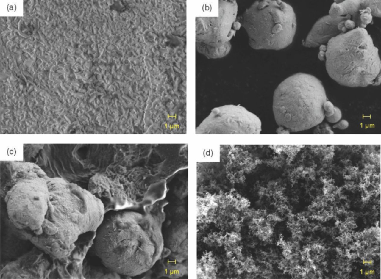
Figure 4. FESEM micrographs of (a) dried agar binder film, (b) Zn powder, (c) pure Zn, and (d) Super P powder.
Figure 5 shows the dispersion of Super P at different concentrations in a porous Zn anode before its application in batteries. At a lower concentration (1 wt%), the Super P particles were located between Zn particles (Figure 5a). At 2 wt% Super P, the accessibility of the Super P particles was appropriately distributed and tended to link the Zn particles (Figure 5b). However, at 3 wt% Super P, the Super P particles started to cover and block the Zn active surface as shown in Figure 5c. Figure 5d shows the maximum blockage on the surface of the Zn particles at 4 wt% Super P. At this loading, the Super P particles almost covered the entire surface of the Zn powder.
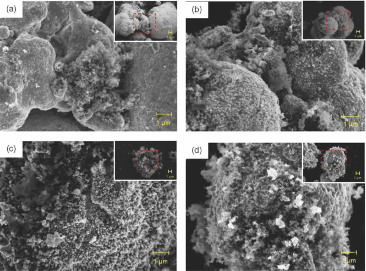
Figure 5. FESEM micrographs of porous anode prior to discharge: (a) Zn1C, (b) Zn2C, (c) Zn3C, and (d) Zn4C. The initial areas of the samples are highlighted (inset).
Super P was used to function as a bridge and to facilitate the electronic path between the Zn particles. If the bridges were fewer (lower concentration of Super P), the electron flow was lower. If the bridges were abundant, the Super P particles tended to cover the Zn particle surface. This blockage reduced the electrochemical reaction, which affects the electrochemical properties of the batteries. Thus, the optimum concentration was observed in Zn2C. Batteries that use Zn2C provide good discharge, power density, and current density. The fluctuations were minimized for this composition because of the linking or bridging effect of Super P to the Zn particles. This scenario indirectly provided higher Zn utilization and continuous electrolyte-electrode reaction.
The Zn-active surface was reduced when Super P reached ≥3 wt%. At only 3 and 4 wt%, the Super P particles not only covered the Zn particle surface but also started to agglomerate. This agglomeration corresponded to the low density of Super P compared with Zn. The active material (Zn) was unable to reach the electrolyte because a high concentration of Super P blocked its surface. As a result, Zn was not consumed.
Figure 6 shows all anode compositions after discharge. The micrograph distinctively shows the progressive changes in the morphology of Zn utilization. Figure 6a displays the needle-like structure obtained after pure Zn was discharged. For the anodes with Super P (Figures 6b–6e), the end product mode was similar (needle-like structure). Although Zn changed, Super P remained between the needle-like structures. Super P was not involved in any reaction and remained the same as in Figure 4d. This finding proves that Super P was inert and did not react with the electrolyte. The primary assumption was that Super P offset the needle-like structure and ensured continuous Zn reactions.
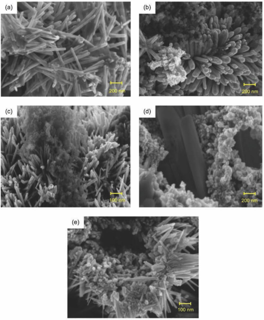
Figure 6. FESEM micrographs of porous Zn anode after discharge: (a) pure Zn, (b) Zn1C, (c) Zn2C, (d) Zn3C, and (e) Zn4C.
Further investigation on the distribution of Super P and Zn particles for Zn2C was conducted using TEM (Figure 7). The raw materials, namely, Super P (Figure 7a) and pure Zn (Figure 7b) particles, were used as control samples. From TEM results, the smallest Zn particle was about 50 nm and the size of Super P was also about 50 nm. The appearance of Super P was quite similar as observed by Gnanamuthu and Lee.12 On the other hand, Zn had a darker image compared with Super P, which was expected because Zn is an electromagnetic material.
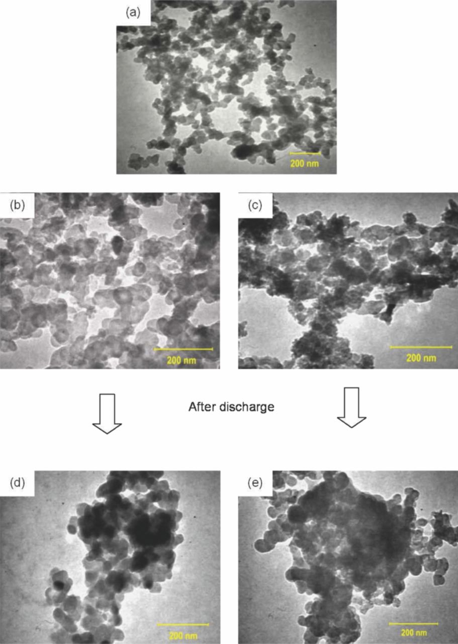
Figure 7. TEM morphologies of (a) Super P; (b) pure Zn and (c) Zn2C anodes before discharge; and (d) pure Zn and (e) Zn2C anodes after discharge.
The TEM image of Zn2C is shown in Figures 7c. Pure Zn and Super P were uniformly scattered and coherently bonded by the agar binder. Figures 7d and 7e show the pure Zn and Zn2C after discharge, respectively. The distribution of Super P accompanied the reacted Zn particles even after discharge characterization. This observation is in agreement with the FESEM results and discharge characteristics, where Super P maintained the route that non-reacted Zn can utilize.
The bigger sizes of Zn particles were not captured in the figures because the magnification range of TEM observations were reduced to 200 nm to match the size of Super P. The image in Figure 8a reveals that Super P was located between the Zn particles. Super P has a significant function as an improved connector to the active material compared with Zn without Super P. Figure 8b illustrates the bridging phenomenon. The schematic explains that Zn and Super P are linked to each other. The green line from point A to B illustrates the ordinary path in the porous Zn anode. However, the link becomes critical when the Zn particles are covered by a thick oxide layer during discharge. This oxide layer is not a conductive material, thereby reducing the electrochemical properties of the batteries.14 The unconnected route at the Zn particles (C to D) is overcome with the introduction of Super P in the system. Super P facilitates the Zn particle to produce a better network, for example, A–C–D–B. Although the needle-like structures grow during the Zn2C discharge, the Zn particles are already connected with Super P in the first place. The connection reduces direct blockage by the needle-like structure to the Zn particles and avoids early failure of the Zn-air battery.
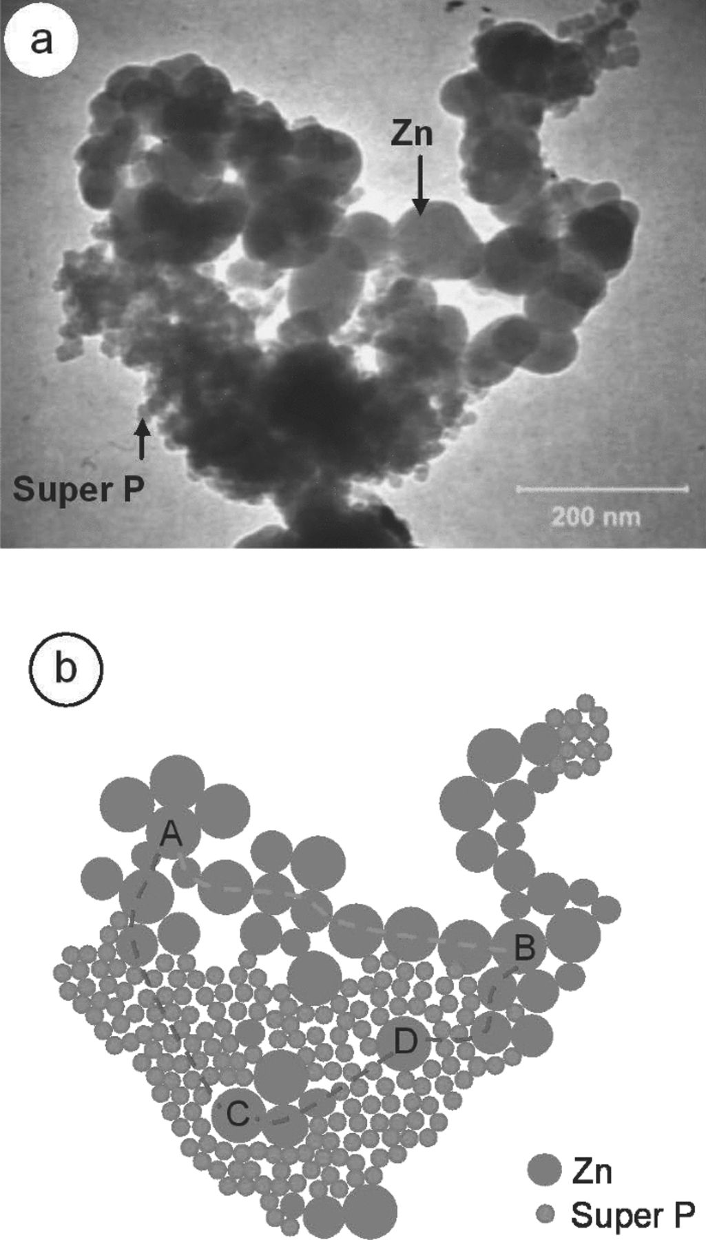
Figure 8. Arrangement in the porous Zn anode: (a) TEM image of Zn2C and (b) illustration of the microstructure of porous Zn anode made of Zn and Super P powder.
Structural analysis
XRD was carried out to study the change in structure of pure Zn. Figure 9 compiles the XRD patterns before discharge of the Zn anodes with various Super P concentrations. Figure 9a shows the pattern for pure Zn with the agar binder. Given that the agar binder is amorphous,14 the Zn peaks dominated the pattern and the strongest line was 2θ = 43.23° with plane (101), followed by 36.29° and 38.99° with planes (002) and (100), respectively. The agar binder, which is an inactive electrochemical material,14 did not affect the morphology of Zn.
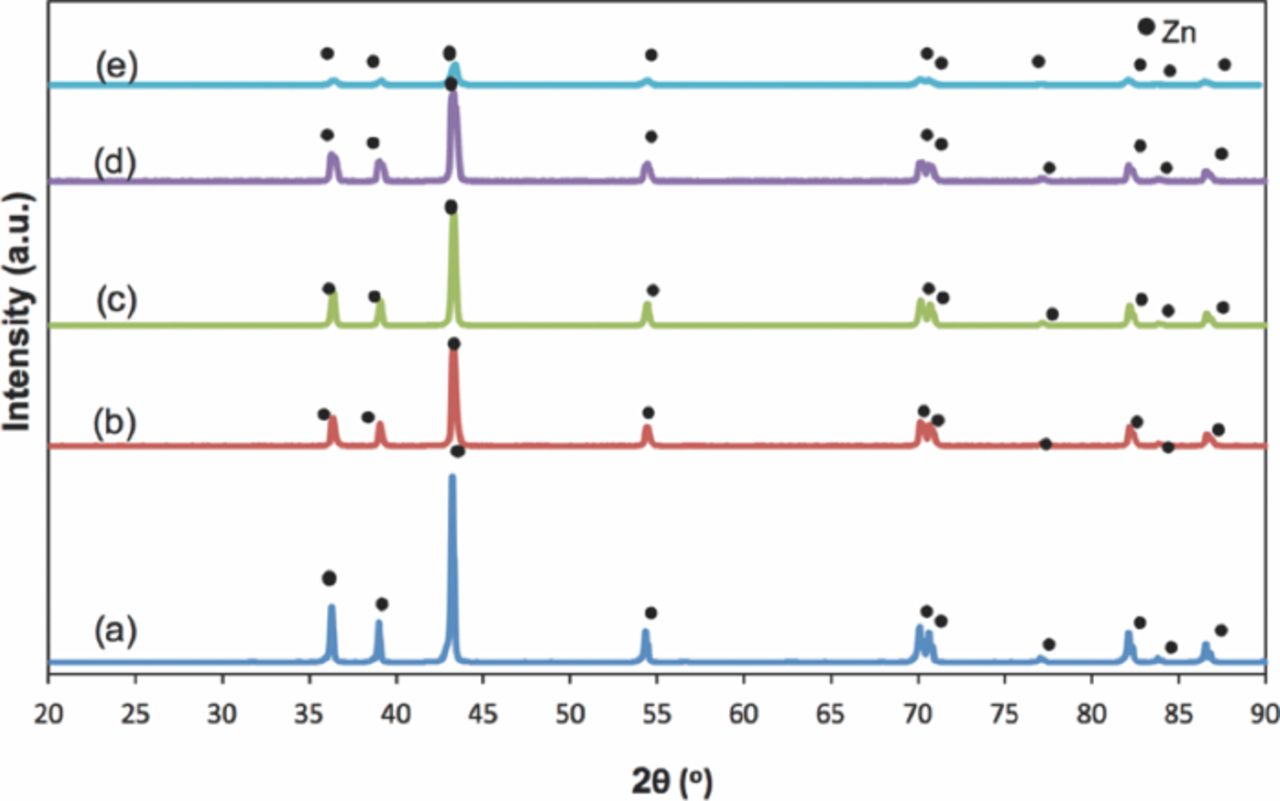
Figure 9. XRD patterns of porous Zn anode before discharge: (a) pure Zn, (b) Zn1C, (c) Zn2C, (d) Zn3C, and (e) Zn4C.
Figures 9b–9e shows the XRD patterns with respect to the effect of Super P concentration on the porous Zn anode system. Compared with the control sample (Figure 9a), an XRD pattern similar to pure Zn was obtained. Hence, the presence of Super P did not affect the Zn powder. The surface of Zn was positively unchanged even in the areas where the Zn particles were accessible to Super P, which corresponds to the obtained XRD result. Zn4C obtained the lowest peak because of the high Super P concentration. Super P started to cover the entire Zn active surface as observed in FESEM. This finding verifies that the presence of Super P was excessive at this concentration.
Figure 10 shows the post discharge of Zn-air battery anodes. The trend of the peaks at 2θ = 31.75°, 34.44°, and 36.25°, which correspond to the (100), (002), and (101) planes, was significant. The observed peaks were comparable to ICDD No. 00-005-0664. Thus, the formations of new phases were observed as ZnO, and correspond to the end product of the discharge process. The formed oxide layer prevented pure Zn from participating further in the electrochemical conversion. This result was in accordance with that of a previous work, where the cross-section showed the areas of Zn and ZnO.17 The XRD pattern in Figure 10a confirms that the needle structure obtained from FESEM was ZnO. Figures 10b and 10c indicate the extensive formation of ZnO peaks in the discharge processes that involved Zn1C and Zn2C, respectively. At higher concentrations of Super P (3 and 4 wt%), Super P perturbed the Zn active particles, and then blocked the full utilization of Zn. Thus, the observed Zn peaks detected by XRD correspond to the unused Zn. These results were consistent with those of Braam et al.,10 who studied porous anodes after discharge. The loss of route contact in the porous network of Zn particles corresponds to the formation of a ZnO resistive layer.
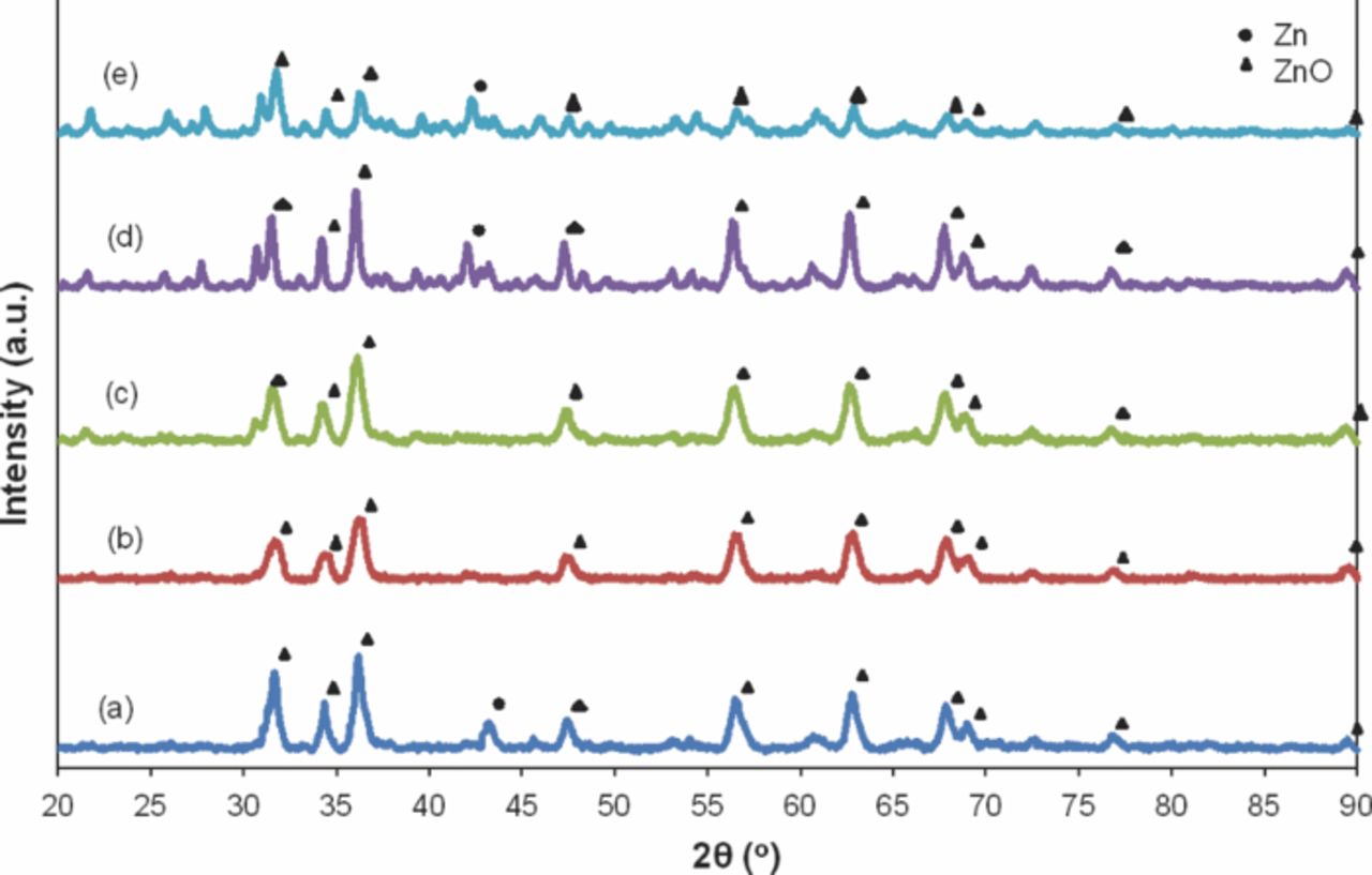
Figure 10. XRD patterns of porous Zn anode post discharge: (a) pure Zn, (b) Zn1C, (c) Zn2C, (d) Zn3C, and (e) Zn4C.
Conclusions
This study showed the effect of Super P carbon black addition on a porous Zn anode. With this addition, the effects on the specific discharge capacity of Zn-air batteries as a function of composition, morphology, and structure were examined. At low concentrations of carbon black, the carbon particles were randomly distributed, which left a large gap between carbon particles on the Zn surface. However, when the carbon concentration was increased, the carbon particles covered the whole surface of Zn. At 2 wt% Super P, the distribution of the carbon particles was uniform and are close to the Zn particles. The Zn electrode with 2 wt% Super P displayed a high specific discharge capacity (776 mA h g−1), improved power density (20 mW cm−2), and stable voltage (1.4 V). The characterization of Zn-air battery with Super P as an additive in a porous Zn anode was limited to improve the specific discharge capacity and stabilize the voltage. The presence of Super P in the porous Zn anode allowed the formation of a continuous network of Zn particles. Super P functioned as a bridge between the networks of Zn particles. These results suggest that porous Zn anode with Super P additive was suitable for use in Zn-air battery applications.
Acknowledgments
MNM thank MOSTI for the NSF scholarship and USM-RU-PRGS for the financial support (Grant No. 8041004). AAM thank the Science Fund (Grant No. 304.PBahan. 6035277).