Abstract
While the energy and power density of lithium-ion batteries (LIBs) are steadily improving, thermal safety continues to remain a critical challenge. Under abuse conditions, exothermic reactions may lead to the release of heat that can trigger subsequent unsafe reactions. The situation worsens in a module configuration, as the released heat from an abused cell can activate a chain of reactions in the neighboring cells, causing catastrophic thermal runaway. This work focuses on experimental elucidation and analysis of different LIB module configurations to characterize the thermal behavior and determine safe practices. The abuse test consists of a heat-to-vent setting where a single cell in a module is triggered into thermal runaway via a heating element. The cell-to-cell thermal runaway propagation behavior has been characterized. Results have shown that increasing the inter-cell spacing in a module containing cylindrical cells significantly decreases the probability of thermal runaway propagation. Additionally, it was determined that appropriate tab configuration combined with cell form factors exhibit a major influence on thermal runaway propagation. Different thermal insulation materials have been analyzed to determine their ability to ameliorate and/or potentially mitigate propagation effects.
Export citation and abstract BibTeX RIS

This is an open access article distributed under the terms of the Creative Commons Attribution Non-Commercial No Derivatives 4.0 License (CC BY-NC-ND, http://creativecommons.org/licenses/by-nc-nd/4.0/), which permits non-commercial reuse, distribution, and reproduction in any medium, provided the original work is not changed in any way and is properly cited. For permission for commercial reuse, please email: oa@electrochem.org.
Lithium-ion batteries offer high specific energy and power but can undergo thermal instabilities that lead to safety issues with large modules.1 During off-nominal conditions such as overcharge, short circuit, or impact, individual cells may reach elevated temperatures where various exothermic side reactions such as solid-electrolyte interphase decomposition, anode/cathode reactions with the solvent, and the vaporization and potential combustion of the electrolyte can occur.2–7 These side reactions can subsequently trigger further reactions, and cause the cell to release tremendous amounts of thermal energy that is sometimes accompanied by cell rupture and/or fire.8 The heat released during this thermal runaway event may propagate to adjacent cells, causing them to release additional heat until the entire module goes into thermal runaway. This module-level thermal runaway scenario must be avoided, especially in applications where safety is paramount such as in the aerospace and automotive industries. Safety devices such as current interrupt devices (CID), positive temperature coefficient (PTC) devices, and flame retardants can help reduce the chance of thermal runaway propagation.9–13 Many researchers have studied the parameters that influence the onset of thermal runaway in order to improve LIB safety.14–16 The effect of battery materials and manufacturing techniques on thermal behavior has been analyzed in several studies.17–22 However, experimental abuse testing of LIB modules is often used to determine thermal behavior in situ.23
In many cases, battery designers are concerned with not only the onset of thermal runaway in one cell, but the propagation of thermal runaway to cells in close proximity to the cell experiencing abuse.24 The thermal energy released from the exothermic reactions occurring in one cell can transfer to adjacent cells, causing them to heat rapidly, initiating a cell-to-cell chain reaction. As many applications use battery modules that are assembled with smaller cells, this propagation scenario can be disastrous. Each cell that is added to a thermal runaway reaction contains additional energy to continue the reactions.25 Typically, designers are under pressure from the customers to design modules that are as compact and lightweight as possible, while increasing energy and power density. Because of this, cells are often installed with less than 1 mm of spacing between them, or even installed in contact with adjacent cells. Such modules experience particularly severe runaway reactions, making it desirable to increase the cell separation from a safety standpoint. In addition, modules with banks of cells in parallel present another safety concern. Should one cell experience an internal short due to physical damage or melting of the separator, it can act as a short for the entire bank, leading to an external short condition for the remaining cells. This can rapidly heat the adjacent cells because of the rapid rate of discharge from the adjacent cells as well as a large amount of current being discharged (or dumped) into the failed cell, leading to rapid thermal runaway propagation. Our studies showed that the configuration of the cell to cell connection tabs in a bank could be selected such that a short caused by an abuse condition would not affect the entire bank. Additionally, the tab location on an individual cell can have an effect on the heat generated under both nominal and abuse conditions.26
The electrolyte vapor and fire released from cell vents could also contribute to heating of adjacent cells, indicating that the direction of expelled vapors, smoke, and fire needs to be controlled by the module design. Various thermal insulation materials such as radiant barriers or intumescents could provide protection from vented electrolyte. A radiant barrier provides protection from direct flame and reduces the rate of radiative heat transfer, as shown in the subsequent analysis. This is particularly useful in protecting cells as an abused cell can reach temperatures over 600°C, where radiation heat transfer is significant. Intumescent materials have been used extensively to add fire protection to structural members in building construction.27–29 These materials chemically react at elevated temperatures and transform from a thermoplastic to a dense insulating ash.30–32 The exact mechanism of this reaction varies with the chemical composition of the intumescent and the plastic carrier in which it is suspended.33,34 Once this chemical reaction occurs, the dense ash could protect the neighboring cells from direct flame released from an abused cell. Some researchers have even proposed that flame retardants be added to cell internal components, increasing safety, sometimes at the cost of decreased capacity.35
The objective of this study is to understand the effect of module configurational parameters such as cell spacing, cell interconnecting tab style, cell form factor, and protection materials on the propagation of thermal runaway. An experimental approach is used to determine the thermal propagation behavior of cells in different module configurations that were subjected to a thermal ramp. Figure 1 shows the two form factors and two tab styles that were analyzed in this work.
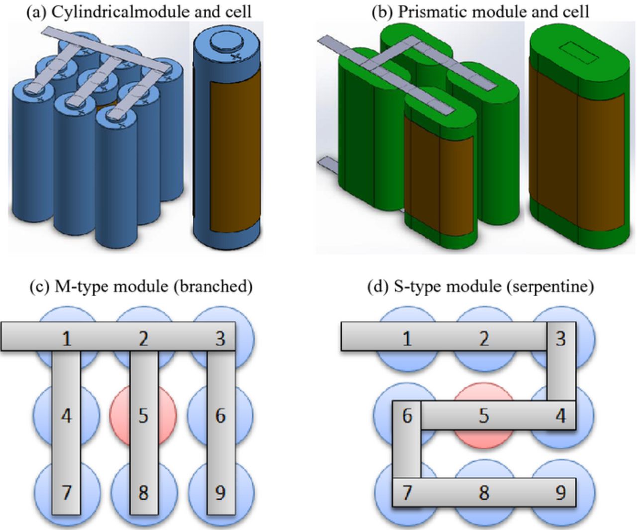
Figure 1. (a) 9P module and a single cylindrical spiral-wound 18650 cell with flexible heater element installed. (b) 4P module and single prismatic spiral-wound cell with heater element. Cell interconnect designs and numbering schemes for (c) M-type tab configuration and (d) S-type tab configuration for the 9P 18650 modules. Note that cell 5 is the triggered cell.
Methodology
Lithium-ion batteries are constructed with an anode, cathode, separator, current collectors, and electrolyte. During normal operation, lithium ions move via diffusion and migration from one electrode to the other through the electrolyte and separator. The electrons paired with each lithium-ion move through the current collector of one electrode, travel through the external load, and terminate at the opposite electrode. During this process, heat is generated within the cell via three primary mechanisms. The first is the reversible heat, caused by the entropy change associated with the redox reactions that occur during lithiation and de-lithiation, also called entropic heat. The second is the irreversible heat associated with the electrode polarization caused by the overpotential in the cell. Lastly, there is irreversible heat associated with ohmic losses, called Joule heating, due to the movement of the lithium ions and electrons within the cell. Under normal conditions, the self-generated heat is very low and typically inconsequential and can be dissipated via a good battery design or a battery thermal management system, with ease.36
However, under abuse conditions, several side reactions can occur that cause an uncontrolled rise in temperature, called thermal runaway. The scenarios under which these reactions can occur are commonly studied via several abuse tests, shown in Table I. These side-reactions are typically exothermic and can heat the cell further to activate additional side-reactions, leading to thermal runaway. While the available data on the side-reactions that occur during thermal runaway varies significantly, the typical reaction progression is detailed in Table II. The catastrophic side-reactions occur as the reactivity of the electrode components increases exponentially by the Arrhenius equation37
![Equation ([1])](https://content.cld.iop.org/journals/1945-7111/162/9/A1905/revision1/jes_162_9_A1905eqn1.jpg)
where Ri(s− 1) is the reaction rate, Ai(s− 1) is the reaction frequency factor, Ea(Jmol− 1) is the reaction activation energy, R(Jmol-1K-1) is the gas constant, T(K) is the local cell temperature, ci is the concentration of the reacting species, and m is the reaction order. Should a cell experience thermal runaway due to some abuse condition, the heat released from the reactions can spread to the neighboring cells causing them to react. The rate at which heat is transferred from a triggered cell to another cell is influenced by the module design. For example, if a module is made of 18650 cylindrical cells, the dominant methods of heat transfer are conduction through the tabs, conduction through the surrounding air or other materials that are in contact, and radiative heat transfer. For the two cell system shown in Figure 2, Fourier's law of heat conduction can be applied such that38
![Equation ([2])](https://content.cld.iop.org/journals/1945-7111/162/9/A1905/revision1/jes_162_9_A1905eqn2.jpg)
where Qcond, tabs(W) is the heat transfer rate via conduction through the tabs, ktab(Wm-1K-1) is the tab thermal conductivity, Ac(m2) is the tab cross-sectional area, T1(K) is the trigger cell temperature, T2(K) is the adjacent cell temperature, and w(m) is the length of the tab. To account for the heat transfer via conduction through the air, a shape factor approach can be used since the length of the cells is greater than the cell diameter and separation. For the two cylindrical cells,
![Equation ([3])](https://content.cld.iop.org/journals/1945-7111/162/9/A1905/revision1/jes_162_9_A1905eqn3.jpg)
![Equation ([4])](https://content.cld.iop.org/journals/1945-7111/162/9/A1905/revision1/jes_162_9_A1905eqn4.jpg)
where Qcond, air(W) is the heat transfer rate via conduction through the air, S(m) is the shape factor, kair(Wm-1K-1) is the air thermal conductivity, T1(K) is the trigger cell temperature, T2(K) is the adjacent cell temperature, L(m) is the cell length, and w(m) is the cell separation measured from the center axis, D1(m) is the diameter of cell 1, and D2(m) is the diameter of cell 2. These equations imply that the heat transfer rate is inversely proportional to the distance between the cells, so increasing cell spacing should reduce the chance of thermal runaway propagation and improve safety. However, during thermal runaway cell temperatures can reach over 500°C, and radiation becomes significant. Radiative heat transfer between two diffusegrey bodies can be considered as
![Equation ([5])](https://content.cld.iop.org/journals/1945-7111/162/9/A1905/revision1/jes_162_9_A1905eqn5.jpg)
where Qrad(W) is the heat transfer rate via radiation, σ(Wm-2K-4) is the Stefan-Boltzmann constant, ε1, 2 is the respective cell emissivity, and A1, 2(m2) is respective cell surface area.38 F12 is the view factor for a system with two cylinders of sufficient length given as
![Equation ([6])](https://content.cld.iop.org/journals/1945-7111/162/9/A1905/revision1/jes_162_9_A1905eqn6.jpg)
![Equation ([7])](https://content.cld.iop.org/journals/1945-7111/162/9/A1905/revision1/jes_162_9_A1905eqn7.jpg)
where r(m) is the cell radius.38 This shows definitively that increasing the cell spacing will decrease the rate of heat transfer via radiation. While it is more difficult to measure, electrolyte venting and ignition also influences the rate of heat transfer from a trigger cell to an adjacent cell. It is because of this difficulty that thermal runaway propagation testing is performed. Table III shows the estimated heat transfer rates for each of these modes between two 18650 cells at 1, 2, and 4 mm, where the cells are at temperatures of 500 and 100°C. Intuitively, the total heat transfer rate decreases with increasing spacing.
Table I. Abuse test methods for lithium-ion cells.16,39
| Abuse test | Type | Description |
|---|---|---|
| Oven test | Thermal | Cell is subjected to sustained elevated temperatures |
| External short-circuit test | Electrical | Cell terminals are shorted by a low resistance (<5 mΩ) leading to rapid discharge |
| Overcharge test | Electrical | Cell is charged past the cut off voltage to a pre-determined SOC |
| Nail penetration test | Mechanical | Cell is pierced by a conductive material leading to internal short-circuit and subsequent rapid discharge |
| Crush test | Mechanical | Cell is compressed until internal short-circuit and rapid discharge |
Table II. Side reactions that can occur during thermal runaway in a typical LiCoO2 battery.16
| Reaction | Onset Temperature (°C) | Heat Release (J/g) |
|---|---|---|
| SEI Decomposition | 70–85 | 186–257 |
| Negative/solvent | 110–150 | 350–1714 |
| Positive/solvent | 167–260 | 265–625 |
| Positive decomposition | 178–250 | 146 |
| Electrolyte decomposition | 155–285 | 155–285 |
Table III. Estimated heat transfer rates between an abused and adjacent cell at different spacing.
| w (mm) | Qcond,tab (W) | Qcond,air (W) | Qrad (W) | Qtotal (W) |
|---|---|---|---|---|
| 1 | 5.69 | 7.13 | 4.98 | 17.80 |
| 2 | 5.34 | 5.06 | 4.63 | 15.03 |
| 4 | 4.77 | 3.61 | 4.05 | 12.43 |
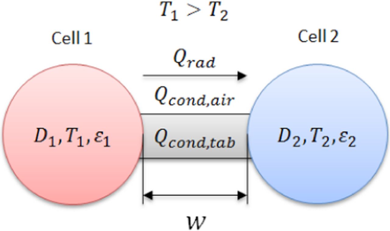
Figure 2. Diagram of heat transfer modes in a representative two cylindrical cell system. Cell 1 is a cell undergoing thermal runaway.
Artificial heating abuse test
The heat-to-vent, or artificial heating abuse test, can be performed either in an enclosed chamber or on an open table, provided blast screens are used. A single cell in a multi-cell module was preinstalled with a thin 2 inch square Kapton heating tape designed to heat the cell to a temperature that initiates thermal runaway, typically above 140°C. Figures 1a and 1b show models of the cells that were used in this study with the heater installed. The propagation of thermal runaway to neighboring cells was monitored by measuring the temperature of each cell using K-type thermocouples installed near the header of the cells. Ambient temperature was also monitored via thermocouples throughout the test. At the start of the test, 20 V and 1 A was applied to the trigger cell using a regulated power supply for 20 W of heating. The heater power was shut off once the trigger cell went into thermal runaway which was monitored using live video capture. Depending on the module configuration, either cell or bank voltages were monitored during the test. Pre- and post-test open circuit voltages (OCV) for each cell were recorded. Post-test OCVs were recorded after disconnecting the cells in the test modules. Additionally, pictures and live videos were recorded from two angles during the tests. All data was sampled at a rate of 10 Hz to capture the rapid change in temperature during a thermal event. Lastly, for enclosed chamber tests, a nitrogen gas pre- and post-purge was used for test consistency and safety. Before the test, each test article was cycled at least twice according to the manufacturer's charge and discharge specifications and the test articles were at either 100% state-of-charge (SOC) or 50% SOC for the tests. The 50% SOC was obtained by fully charging the cells and then removing 50% of the capacity bringing it down to 50% depth of discharge (DOD). The cells at 50% DOD are referred to as 50% SOC also in this paper.
Two different cells were tested in this work. The first was a cylindrical spiral-wound 18650 cell, and the second was a prismatic spiral-wound cell. The specifications for each cell type are outlined in Table IV. The most notable differences between the two cells are that the prismatic cell is nearly twice the weight, volume, and capacity of the cylindrical cell. Additionally, the 18650 cell has a vent located at the top (header) of the cell that allows for an internal pressure release when gas builds up inside the cell. However, the prismatic cell design has two vents located on the same flat side of the cells. These side-facing vents can also be problematic in multi-cell modules as the hot electrolyte vapors and flame are pointed toward neighboring cells, propagating the thermal runaway condition with more ease. The cells were assembled into test modules by resistance welding nickel tabs to the terminals of the cells. The various test article configurations are outlined in Table V. The test modules consisted of either four or nine cells in series or in parallel depending on the test and had various cell spacing (1, 2 or 4 mm). The naming convention for the electrical configuration starts with the number of cells followed by a P or S for parallel or series, and the cell form factor. Additionally, the tab connection configuration was varied with the M-type tabs being a branched approach and the S-type a serpentine approach, as shown in Figures 1c and 1d. For the nine-cell modules, the center cell, cell 5, was heated using the thin-film heater (shown installed on the 18650 cell in Figure 1a). Figure 1b shows the heater installed on the prismatic cell. For the four-cell modules, cell 2 was forced into thermal runaway.
Table IV. Cell specifications and recommended operating conditions.
| Model | Cylindrical | Prismatic |
|---|---|---|
| Capacity (Ah) | 2.8 | 5.3 |
| Max Voltage (V) | 4.35 | 4.2 |
| Min Voltage (V) | 3.0 | 2.75 |
| Max Discharge (A) | 4.05 | 13 |
| Max Charge (A) | 2.7 | 10.6 |
| Dimensions (mm) | 18 × 18 × 65 | 19 × 64.8 × 37.3 |
| Mass (g) | 47.0 | 93.5 |
| Discharge Temp (°C) | −20 to 60 | −40 to 70 |
| Charge Temperature (°C) | 0 to 45 | −20 to 60 |
| Vent Location | Header | 2 side vents |
Table V. Module specifications and general test plan.
| Cell | Electrical | Tab | Spacing | SOC | Material | Result |
|---|---|---|---|---|---|---|
| Cylindrical | 9P | M-type | 1 mm | 100% | None | Figure 3 |
| Cylindrical | 9P | M-type | 2 mm | 100% | None | Figure 4 |
| Cylindrical | 9P | M-type | 4 mm | 100% | None | Figure 5 |
| Cylindrical | 9P | S-type | 1 mm | 100% | None | Figure 6 |
| Cylindrical | 9P | S-type | 2 mm | 100% | None | Figure 7 |
| Prismatic | 9S | Alternating | 2 mm | 100% | None | Figure 8 |
| Prismatic | 4P | M-type | 8 mm | 100% | Radiant Barrier | Figure 9 |
| Prismatic | 4P | M-type | 8 mm | 50% | Radiant Barrier | Figure 10 |
| Prismatic | 9P | M-type | 5 mm | 50% | Intumescent | Figure 11 |
To decrease the chance of thermal runaway propagation of the prismatic cells, insulation materials were installed between the cells because of their side-facing vents. The first material was a radiant barrier, which consists of a heat-resistant fiber material sandwiching multiple layers of highly reflective metal foil. This barrier is designed to block the electrolyte vapors and flame and also severely limits the radiation heat transfer by the presence of the layering material. The next test material was a fire-resistant intumescent block that physically separates the cells from one another. Intumescents are often used to give structural members in buildings up to 2 hours of fire resistance, tested by ASTM E119. The Intuplas (Lithium Prevent) material transforms from a white thermoplastic into a dense, thermally insulating ash, starting at around 80°C. The heat released by a cell undergoing thermal runaway will activate this material, isolating the heat from neighboring cells.
Results and Discussion
The present work details the thermal runaway propagation behavior of the lithium-ion battery modules that were described previously. The cell temperatures during the constant-power heater test are reported along with cell and bank voltages when applicable. Open circuit voltages were recorded for each cell before and after the test. Photographs were taken after each test to characterize visible damage. For the 9-cell configurations in the subsequent analysis, physically adjacent cells are those that are direct north, south, east, or west of the trigger cell and diagonal cells are those in the corners of the modules that are significantly further from the center due to the geometry of the modules. Electrically adjacent cells are those that are in direct contact with the trigger cell via tab connections. The thermal runaway event is characterized by the occurrence of an uncontrolled temperature spike, accompanied by cell venting, fire, smoke and/or expulsion of contents and a post-test OCV of 0 V.
Effect of cell spacing
Every test conducted on the 9P 18650 cell modules with M-type tabs showed that the trigger cell released excessive smoke and experienced very high temperatures, but did not rupture, indicating that the vents worked as designed. In all cases, cells that were physically and electrically adjacent showed higher maximum temperatures and typically showed lower post-test OCVs. This indicates that electrical draining through the shorted trigger cell contributed significantly to the surrounding cells' voltage change. None of the 18650 cell module tests showed thermal runaway propagation to neighboring cells which is typically indicated by sustained temperatures above 200°C. However, there was obvious physical damage in most cases, and voltage loss was also apparent.
For the 9P 18650 module with 1 mm spacing, the cells directly adjacent to the trigger cell showed significant damage in the form of charring from the heat of the trigger cell, as shown in Figure 3. Cells diagonal to the trigger cell showed significantly less visible damage, with some charring or melting of the plastic wrapping. The tab at the trigger cell showed significant damage but maintained an electrical connection. This damage was either due to the excessive resistive heating from high current loads through the tab due to the cell's short circuit, or due to the very hot electrolyte vapors and smoke ejecting from the cell vents. The post-test OCVs indicate that the adjacent cells sustained significantly more damage than the diagonal cells. The post-test OCVs of cells 1, 3, 7, and 9 were near the initial charge OCV of 4.3 V. The adjacent cells 2, 4, 6, and 8 read 0, 0.6, 2.1, and 0.4 V, respectively. Maximum adjacent cell temperatures ranged from 100 to 125°C (cells 6 and 2) and the maximum diagonal cell temperatures ranged from 70 to 93°C (cells 9 and 7). The thermal runaway trigger temperature recorded on the trigger cell was 204°C with a peak temperature of 665°C.
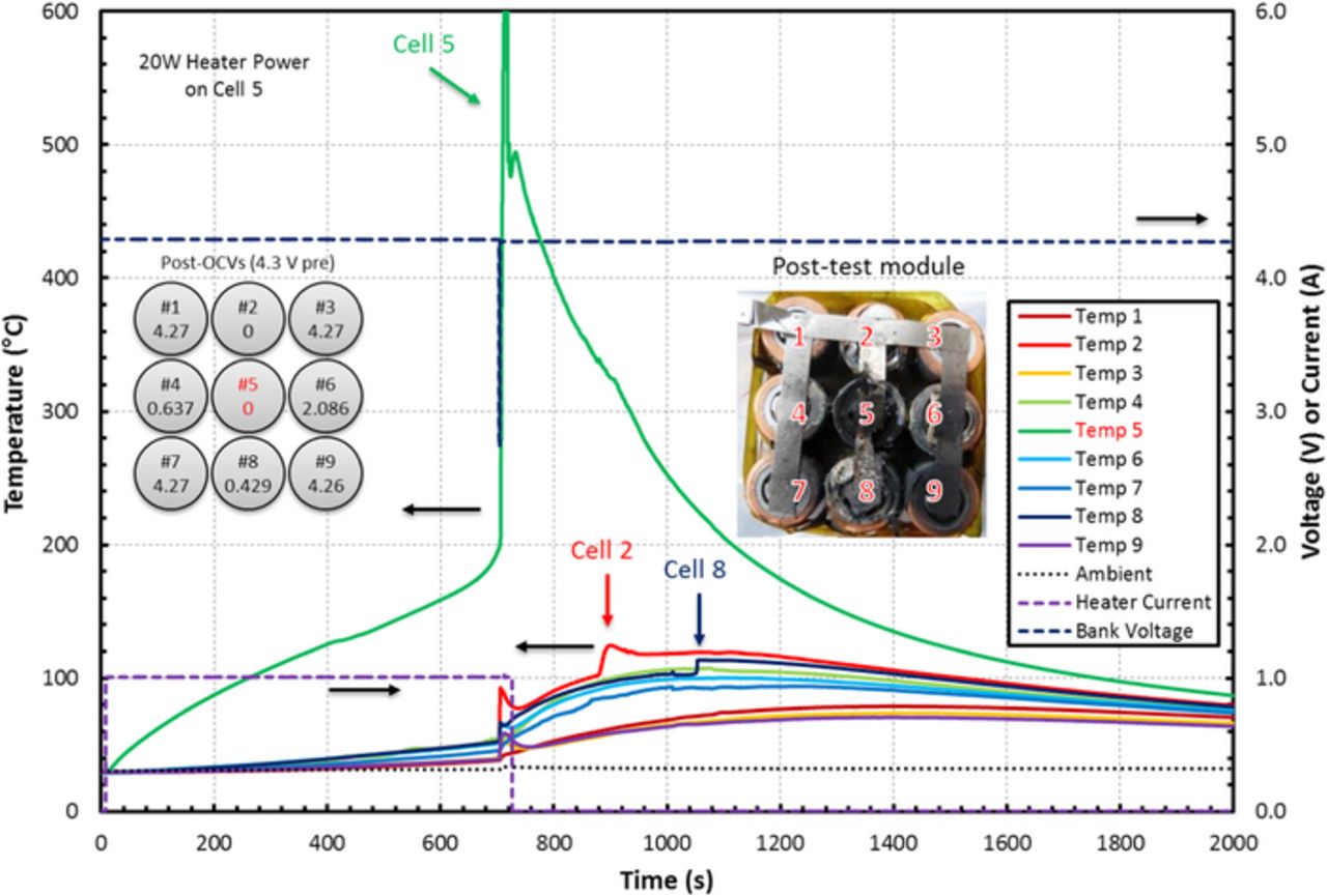
Figure 3. Measured temperature response of each cell in the tested module with heater current, bank voltage, and post-test damage. This module is a 9P 18650 type with M-type tabs, 1 mm spacing, 100% SOC, and no material between the cells. Cell 5 was artificially heated using constant power thin-film heating element. Cells 2, 4, 6, and 8 experienced sustained heating from the thermal runaway of cell 5. The adjacent cells had decreased OCVs and showed significant physical damage whereas the diagonal cells did not.
Next, results of the test on the 9P 18650 module with 2 mm spacing are shown in Figure 4. Cells directly adjacent to the trigger cell showed less damage than that shown in the 1 mm test. There was some charring from heat and smoke from the trigger cell but no melting of the plastic wrapping. Cells diagonal to the trigger cell showed significantly less visible damage with only slight charring. The tab at the trigger cell again showed significant damage and was completely burned off and disconnected. The post-test OCVs indicate that the adjacent cells sustained more damage than the diagonal cells. Cells 1, 3, 7, and 9 read OCVs near the charge OCV of 4.3 V. The adjacent cells 2, 4, 6, and 8 read 2.1, 4.2, 2.56, and 0.187 V, respectively, considerably higher than the readings in the 1 mm case. Maximum adjacent cell temperatures ranged from 88 to 104°C (cells 4 and 8) and the maximum diagonal cell temperatures ranged from 58 to 69°C (cells 7 and 3). Additionally, the thermal runaway trigger temperature recorded on the trigger cell was 186°C with a peak temperature of over 600°C.
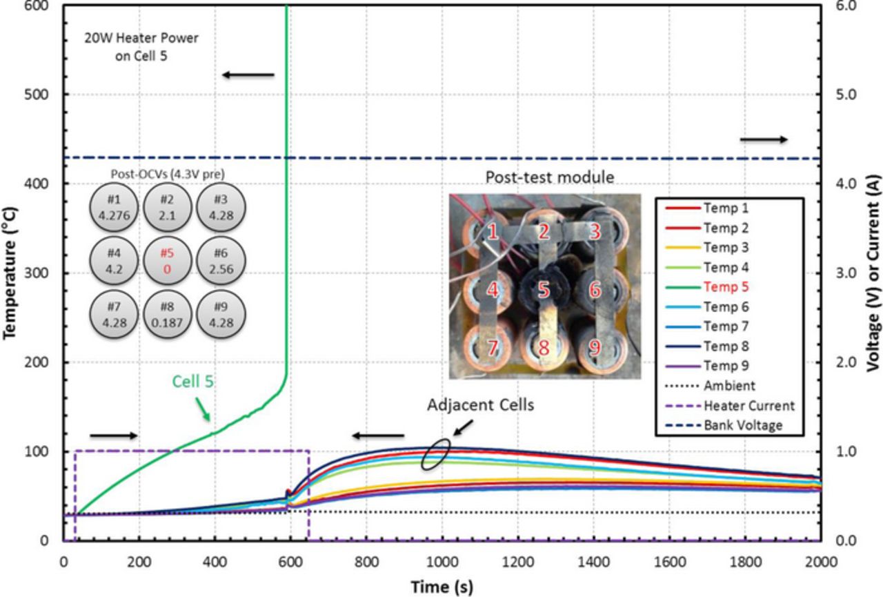
Figure 4. Measured temperature response of each cell in the tested module with heater current bank voltage, and post-test damage. This module is a 9P 18650 type with M-type tabs, 2 mm spacing, 100% SOC, and no material between the cells. Cell 5 was artificially heated using constant power thin-film heating element. Cells 2, 4, 6, and 8 experienced less sustained heating from the thermal runaway of cell 5 than in the 1 mm case. The adjacent cells had higher OCV readings and showed significantly less physical damage than in the 1 mm case.
Lastly, the results for the 4 mm module are shown in Figure 5. The cells directly adjacent to the trigger cell showed little visible damage and the cells diagonal to the trigger cell showed no visible damage. Cells 1, 3, 5, 6, 7, and 9 read OCVs near the charge OCV of 4.3 V. The electrically adjacent cells 2 and 8 read 0.2 and 2.4 V, respectively, indicating considerable electrical draining. The maximum adjacent cell temperatures ranged from 78 to 102°C (cells 6 and 2) and the maximum diagonal cell temperatures ranged from 56 to 64°C (cells 7 and 1). Lastly, the thermal runaway trigger temperature recorded on the trigger cell was 189°C with a peak temperature of 581°C.
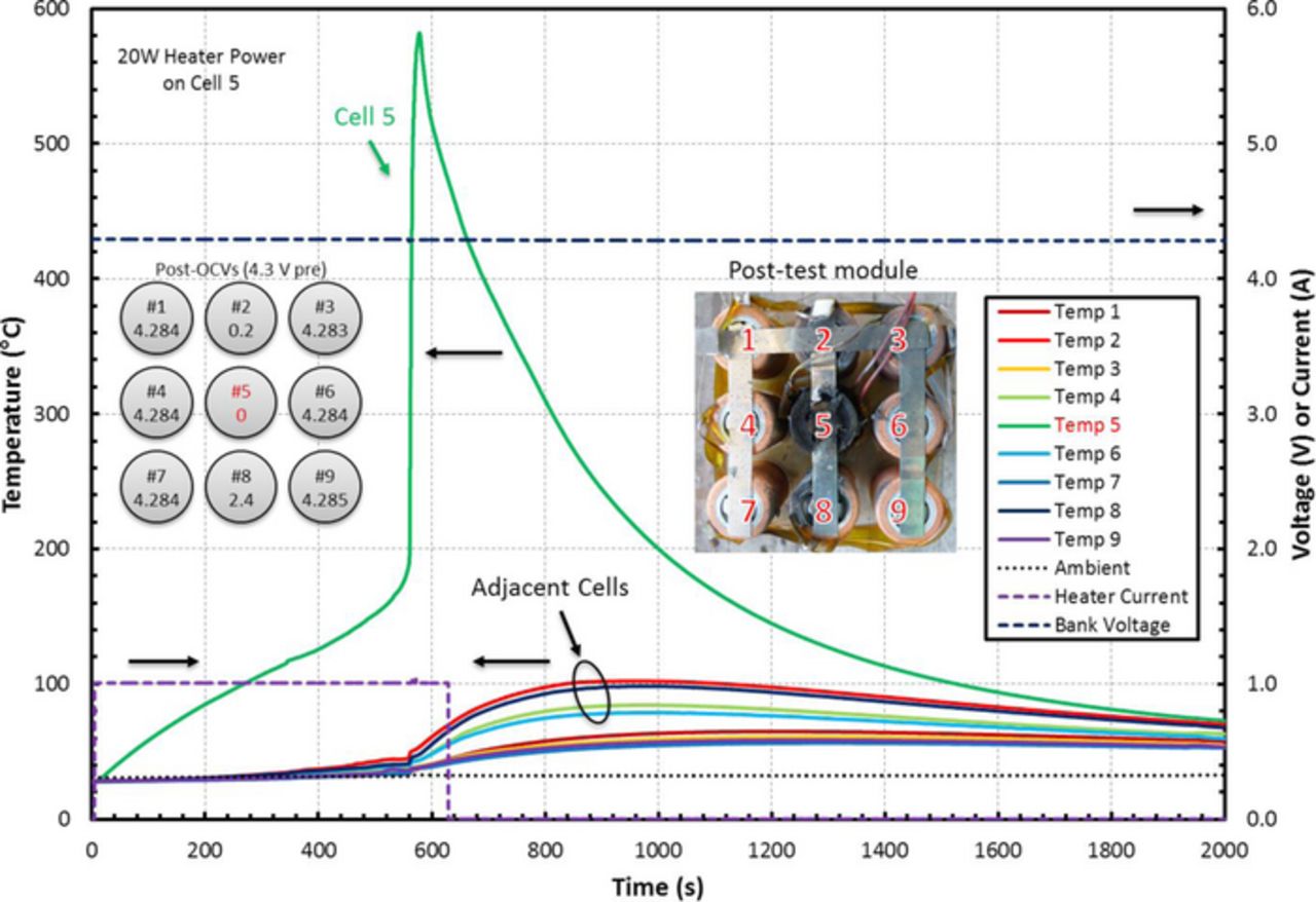
Figure 5. Measured temperature response of each cell in the tested module with heater current bank voltage, and post-test damage. This module is a 9P 18650 type with M-type tabs, 4 mm spacing, 100% SOC, and no material between the cells. Cell 5 was artificially heated using constant power thin-film heating element. Cells 6 and 8 experienced less sustained heating from the thermal runaway of cell 5 than in the 2 mm case whereas cells 2 and 4 were heated nearly the same as in the 2 mm case. Only cells 2 and 4 showed decreased OCV readings and overall there was less physical damage than in the 2 mm case.
It is clear from the outcomes of these tests that increasing the cell spacing drastically decreases the damage sustained by the neighboring cells as expected from the previously outlined heat transfer analysis. The average adjacent cell temperatures for the 1, 2, and 4 mm spacing were 111, 96, and 91°C respectively. Additionally, the maximum adjacent cell temperatures for the same tests were 125, 104, and 102°C. Since the rate of heat transfer via radiation and conduction through the tabs decreases with increased distance, the increased spacing decreased the neighboring cell's temperature rise. The post-test voltages of the cells decreased due to the electrical draining through the shorted trigger cell, PTC device activation, or CID activation (in cells that measured lower than 0.5 V). In general, a spacing of at least 2 mm is recommended for modules using 18650 cells due to the drop in maximum adjacent temperature from 125 to 104°C.
Effect of cell interconnect design
The tests for the modules with M-type tab connections indicate that electrical draining through the shorted trigger cell could have a significant effect on the voltage of the other cells in the module. The damage propagation was studied for modules with S-type tabs and compared with the M-type tab modules. The results of the test on the 9P 18650 module with 1 mm spacing and S-type tabs are shown in Figure 6. The cells directly adjacent from the trigger cell showed significant damage in the form of charring and melting of the cell wrap from hot expelled electrolyte and smoke. The cells diagonal to the trigger cell showed significantly less visible damage, with some charring or melting of the plastic wrapping, in a manner similar to the M-type tab module test. In the S-type case however, the trigger cell tab was disconnected in two places and all post-test OCVs read 0 V. This indicates that the neighboring cells were completely drained in voltage from the trigger cell short although they did not vent. Additionally, the maximum adjacent cell temperatures ranged from 115 to 146°C (cells 2 and 4) and the maximum diagonal temperatures ranged from 88 and 95°C (cells 3 and 7), significantly higher than the results from M-type tab module test with the same spacing. Lastly, the trigger temperature recorded on the trigger cell was 119°C with a peak temperature of 462°C.
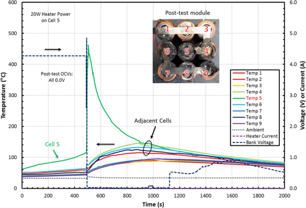
Figure 6. Measured temperature response of each cell in the tested module with heater current bank voltage, and post-test damage. This module is a 9P 18650 type with S-type tabs, 1 mm spacing, 100% SOC, and no material between the cells. Cell 5 was artificially heated using constant power thin-film heating element. Cells 2, 4, 6, and 8 experienced sustained heating from the thermal runaway of cell 5. All cells in this case read 0 V for their OCVs. There was slightly more physical damage than in the 1 mm M-type test.
Next, the results of the test on the 9P 18650 module with 2 mm spacing and S-type tabs are shown in Figure 7. In this test, the cells adjacent to the trigger cell showed less damage than in the 1 mm test. There was some charring from the expelled electrolyte but no melting of the plastic wrapping with the exception of cell 4. In addition, cells diagonal to the trigger cell showed little damage, with only slight charring and the trigger cell tab was disconnected in two places. All post-test OCVs read 0 V again indicating that the cells were completely electrically drained. Maximum adjacent cell temperatures ranged from 92 to 125°C (cells 8 and 4) and the maximum diagonal cell temperatures ranged from 59 to 87°C (cells 7 and 1). The trigger temperature recorded on the trigger cell was 200°C with a peak temperature of 639°C.
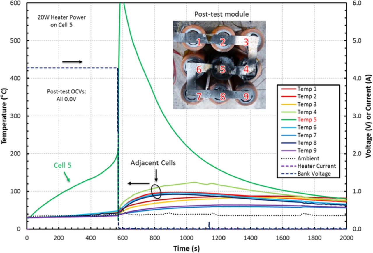
Figure 7. Measured temperature response of each cell in the tested module with heater current bank voltage, and post-test damage. This module is a 9P 18650 type with S-type tabs, 2 mm spacing, 100% SOC, and no material between the cells. Cell 5 was artificially heated using constant power thin-film heating element. Cells 2, 4, 6, and 8 experienced less sustained heating from the thermal runaway of cell 5 than in the 1 mm case. All cells in this case read 0 V for their OCVs. The physical damage in this case is comparable to the 2 mm M-type test.
The modules with S-type tab configuration showed significantly worse behavior than the modules with M-type tab configuration under the same conditions. The S-type module's maximum adjacent cell temperatures were significantly higher with a 42°C increase for the 1 mm cell-spacing modules and a 23°C increase for the 2 mm cell-spacing modules when compared to those recorded for the M-type tabbed modules. Additionally, the post-test OCVs for the S-type tests were consistently all zero voltages, in contrast with the M-type modules that had some cells with full charge voltage after the test. This increase in maximum temperature and decrease in OCV indicates that the S-type tab configuration allows for more electrical draining into the trigger cell than that for the M-type tabbed modules. These results show that a branched style of tab configuration may be safer than a serpentine style for modules with multiple cells in parallel.
Thermal insulation material
Because the prismatic spiral-wound cells have side-facing vents, the thermal behavior of these cells under abuse is particularly interesting. Figure 8 shows the temperature response under 20 W of heater power applied to cell 5. During the first half of the test, cell 5 steadily increased in temperature to nearly 130°C, with cell 8 showing temperatures up to 80°C due to its proximity to the heater. Half-way through the test, a release of electrolyte vapors and smoke occurs and cells 2, 5, and 8 rapidly heat to over 600°C. This indicates that the heat released during the thermal runaway of cell 5 significantly affects the neighboring cells when no inter-cell barrier is provided for protection. This runaway condition also propagates to cells 4 and 7. This result is supported by the drop in cell voltage corresponding to each cell's thermal runaway event. It is evident that simply spacing the prismatic cells away from each other will not sufficiently protect neighboring cells from a cell that had undergone thermal runaway, due to the side facing vents. Installing thermal insulation materials between the cells to block the transfer of heat from the hot ejected electrolyte vapors, smoke, and fire could protect neighboring cells from thermal runaway propagation.
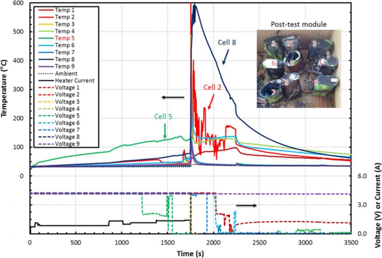
Figure 8. Measured temperature response of each cell in the tested module with heater current, individual cell voltage, and post-test damage. This module is a 9S prismatic type with alternating tabs, 2 mm spacing, 100% SOC, and no material between the cells. Cell 5 was artificially heated using constant power thin-film heating element. Due to the increased heat transfer from the side-facing vents, cells 2, 3, 4, 6, 7, and 8 all experienced either thermal runaway or rapid can burst. All cells except 1 and 9 read 0 V for their post-test OCVs.
The result of the 4P prismatic tests with the radiant barrier installed is shown in Figure 9. The trigger cell ejected its electrode and current collectors rapidly through the entire header assembly during the test. This indicates a rapid increase in internal pressure and a failure of the vents to release the electrolyte vapors and vent products in a controlled manner. The adjacent cells were relatively undamaged, with some dried electrolyte coated on the exterior of the cells and some cells displayed swelling. Additionally, there was no evidence of venting or burned tabs on the other three cells. However, the recorded temperatures showed that the adjacent cells all witnessed elevated temperatures for a short duration. Since temperature measurements were taken on the surface of the cells, the brief elevated temperatures are likely a consequence of quick exposure to the electrolyte vapors instead of sustained heating from thermal runaway. The post-test OCVs of the cells read 4.2 V with the exception of the trigger cell that had lost its cell contents due to the ejection of the contents through the header assembly. Lastly, the trigger temperature recorded on the trigger cell was 157°C with a peak temperature of 496°C.
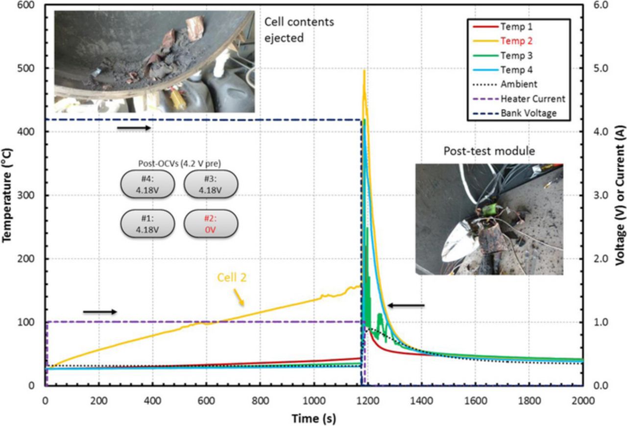
Figure 9. Measured temperature response of each cell in the tested module with heater current, bank voltage, and post-test damage. This module is a 4P prismatic type with M-style tabs, 8 mm spacing, 100% SOC, and radiant barrier between the cells. Cell 2 was artificially heated using constant power thin-film heating element. The contents of cell 2 ejected from the can during the thermal runaway event, so the surrounding cells were not heated enough to initiate a reaction. All cells read full voltage with the exception of cell 2.
To test the effect of pre-test cell state-of-charge on the thermal response of the module, an identical test was conducted with all the cells at 50% depth-of-discharge (DOD), and the results are shown in Figure 10. In this test, the trigger cell vents opened slowly and the electrolyte vapors ignited at a temperature of 157°C. The trigger cell temperature peaked at 700°C and sustained a temperature of greater than 600°C for several seconds during the fire, which appeared to be additionally fueled by the Kapton tape used to secure the thermocouples. Due to the prolonged nature of this event, a significant amount of heat was generated and transferred from cell 2, the trigger cell, to cell 1, which is directly adjacent to the trigger cell. Cell 1 showed significant damage in the form of charring and melted wrapping and appeared to have also vented slowly, but no flame was visible. Cells 3 and 4 were isolated from the trigger cell by the radiant barrier and showed some brief flash heating from the electrolyte flame, but did not sustain high temperatures. These cells did swell slightly, indicating vaporization of the electrolyte, but did not show a thermal event and did not vent electrolyte. With the exception of the quick spikes from the electrolyte fire, the highest sustained temperatures were 119 and 144°C for cells 3 and 4 (the protected cells), respectively. The post-test OCVs were 0, 0, 1.5, and 0.28 V for cells 1 through 4, respectively. The lower voltages observed on cells 3 and 4 may be due to the self-discharge induced by the higher temperatures, but the cells were relatively unharmed despite the observed fire.
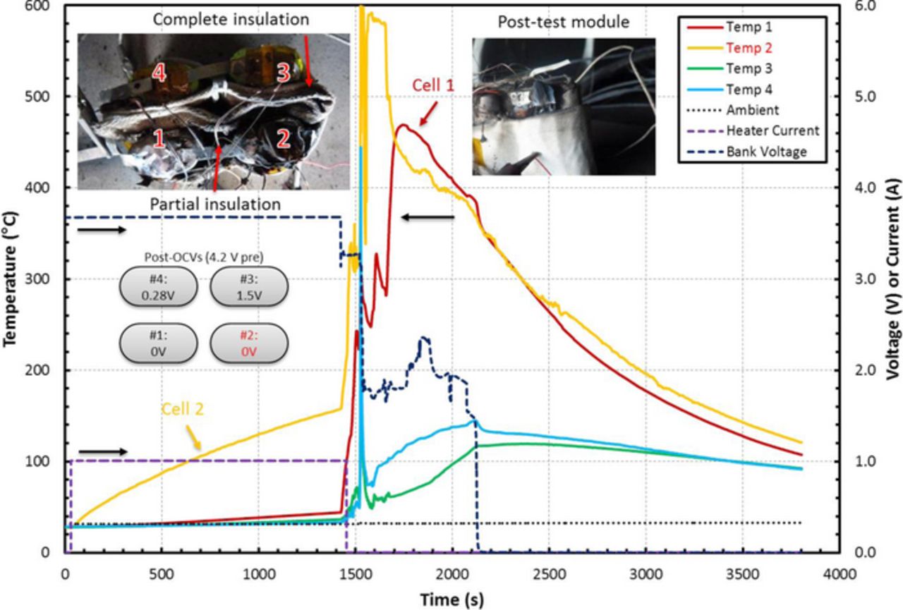
Figure 10. Measured temperature response of each cell in the tested module with heater current, bank voltage, and post-test damage. This module is a 4P prismatic type with M-style tabs, 8 mm spacing, 50% SOC, and radiant barrier between the cells. Cell 2 was artificially heated using constant power thin-film heating element. The electrolyte from cell 2 ignited in this test and caused cell 1 to experience thermal runaway since the radiant barrier does not protect cell 1. However, cells 3 and 4 did not experience thermal runaway and showed little physical damage due to the presence of the radiant barrier. The runaway cells read 0 V post-test, whereas the protected cells only showed decreased voltage.
Next, the intumescent material was tested with a 9P prismatic module to determine its effectiveness at protecting cells adjacent to the abused cell. The pre- and post- test images are shown in Figure 11. Since the ends of the cell were held in place by the intumescent block lids, the cell can remained intact but the cell vented electrolyte and smoke that subsequently ignited. The smoke and fire damaged the cells in close proximity to the trigger cell causing some charring and melting of the plastic wrapping. However, none of the other cells were visibly damaged. The maximum adjacent cell temperatures ranged from 106 to 416°C (cells 8 and 4) and the maximum diagonal cell temperatures ranged from 75 to 164°C (cells 7 and 3). The runaway onset temperature for the trigger cell was 151°C with a peak temperature of 735°C. While the neighboring cell temperature appear to be higher for this test than for the radiant barrier cases, the high temperatures were not sustained for more than 10 seconds, indicating that the flame only resulted in rapidly heating the thermocouple, and was extinguished before the adjacent cells could go into thermal runaway. This is further supported by the post-test OCVs, which were all found to be at 3.76 V with the exception of the trigger cell (that had 0 V), indicating that cells 4 and 6 were sufficiently protected by the intumescent material and only experienced quick heating from the flame.
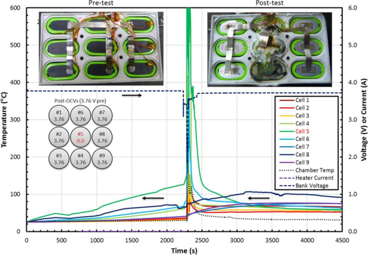
Figure 11. Measured temperature response of each cell in the tested module with bank voltage and post-test damage. This module is a 9P prismatic type with M-style tabs, 5 mm spacing, 50% SOC, and intumescent material between the cells. Cell 5 was artificially heated using constant power thin-film heating element. The intumescent material protected all of the surrounding cells, and as such only the artificially heated cell experienced thermal runaway. All cells read the initial voltage with the exception of cell 5.
In summary, it was shown that insulation materials can prevent the probable propagation of thermal runaway in modules constructed with the prismatic cells. The radiant barrier proved to sufficiently protect cells that were fully covered by the material. This barrier did not provide much rigidity to the cell module, however, as it allowed for the trigger cell to expel its contents in the 100% SOC case. Since the radiant barrier was not consumed during the thermal event, it provided protection during the sustained fire event. The relatively low density of the barrier also makes it desirable in applications where weight is critical. The intumescent material provided more protection in the prismatic cell modules during thermal runaway. The material's rapid change in volume due to the intumescent reaction should be taken into account during battery design and assembly. Additionally, the material nearly doubled the weight of the nine cell modules, which lowers the gravimetric energy density of the modules.
Conclusions
The influence of module design configurations including cell spacing, tabbing style, and vent location on thermal runaway propagation were analyzed experimentally in this work. It was found that increasing the distance between cells decreases the damage experienced by the adjacent cells, decreases cell temperatures, and decreases loss of cell voltages. Based on these results, a cell spacing of at least 2 mm is recommended to minimize the chance of thermal runaway propagation and module damage. Additionally, the tests showed that a branched style of tabbing improves the voltage retention as well as the safety of the modules over a serpentine style of tabbing as the shorted trigger cell is electrically better isolated from the rest of the module when the tabs are branched. The vent location also significantly influenced the design of the barriers used, as thermal runaway propagation cannot be avoided for the cells with side facing vents. To protect adjacent cells from electrolyte vapors, vent products, fire, and smoke that can be released during venting, a radiant barrier and an intumescent material were installed between the cells. Both insulation materials were able to protect surrounding cells from the heat released by the triggered cell. In conclusion, the proper method of minimizing the chance of thermal runaway propagation varies significantly with cell type and module configuration.
Acknowledgments
Financial support from NASA Office of Education is gratefully acknowledged. The cooperation of Pyrophobic Systems is greatly appreciated as they provided us with the flexibility to design the intumescent material modules to better suit our cell designs. Additionally, the support of the Energy System Test Area at NASA Johnson Space Center was invaluable for this work.