
Abstract
Dealloying is a facile method to prepare nanoporous metals. Normally, the formation of nanoporous structure during dealloying is accompanied by a macroscopic volume reduction, which is utilized herein to prepare homogeneous nanoporous Ni (np-Ni) particles by ultrasonic-assisted dealloying Mg-Ni-La metallic glass ribbons in (NH4)2SO4 aqueous solution. Particles with different shapes can be fabricated by adjusting the thickness of the metallic glass ribbons. The np-Ni particles exhibit a ligament-pore structure with a high specific surface area of 53 m2 g−1. The process for particle formation and the ligament structure are discussed. The np-Ni can be applied as an efficient electrocatalyst for hydrogen evolution reaction (HER). To reach a high current density of 100 mA cm−2, it requires merely 46 mV with a small Tafel slope of 21 mV dec−1. Furthermore, the np-Ni particles have a good catalytic stability during water electrolysis without any increase of overpotential for at least 20 h, which may be attributed to the chemical stability of Mg and La in alkaline media and the firm support of the ligament-pore structure. It is expected that the current catalyst can enable the manufacturing of affordable water splitting systems.
Export citation and abstract BibTeX RIS
Dealloying is an effective method to fabricate nanoporous metals by selective dissolution of one or more components out of an alloy.1–9 Many nanoporous metals, like Pd,1 Au,2,3 Pt,4 Ag,5 Cu4,6 and Ni,7–9 have been prepared by dealloying. The formation of nanoporous structure is normally accompanied by a macroscopic volume reduction.10,11 It is reported that there is a macroscopic shrinkage by up to 30 vol.% during electrochemical dealloying of a Ag-Au alloy.10 Normally, volume shrinkage should be minimized in order to fabricate monolithic nanoporous metals with good mechanical properties, otherwise many cracks may occur. Various strategies have been utilized to fabricate crack-free nanoporous metals by dealloying.12–15 However, nanoporous metals in the powder form have their own advantages over the monolithic form in some applications. Herein, the volume shrinkage is utilized to prepare nanoporous Ni (np-Ni) particles by dealloying. Ultrasonic is introduced to accelerate the cracking during dealloying. Besides, ultrasonic may have a potential contribution to the breakage of initial oxide layer and have a possible stabilization effect for np-Ni.16
The np-Ni can be used as an electrocatalyst toward hydrogen evolution reaction (HER). As is widely known, hydrogen generation through water electrolysis offers an attractive avenue to store energy from renewable resources, which can greatly relieve the tension between the growing demand for energy and environmental concerns.17–21 Efficient electrolytic hydrogen generation heavily relies on active, durable and affordable catalysts to lower the overpotential for electrode reactions and thus improve the electrolytic efficiency.22–24 Ni, its alloys and compounds are the most attractive non-precious HER catalysts, due to their good electrocatalytic activity and high corrosion resistance in strong alkaline environment.25–29
Dealloying is an effective method to enhance the catalytic performance of Ni and Ni-based alloys toward HER by increasing the specific surface area.30,31 With a high specific surface area, Raney Ni shows an enhanced activity toward HER.30,32–34 It is fabricated by dealloying, i.e. leaching Al/Zn out of Ni-Al/Ni-Zn alloy in alkaline metal hydroxide solutions.30,32–34 However, Raney Ni experiences extensive deactivation as a cathode during alkaline water electrolysis due to the dissolution of residual Al/Zn in caustic solutions.21,35–37 In addition, Raney Ni is commonly described as an agglomerate of mainly nickel nanoparticles,38–40 which may lead to recrystallization and sintering when the temperature is raised and thus also result in a progressive deactivation.37 Therefore, it is of great importance to develop new dealloying precursors without elements that may dissolve in caustic solutions. Besides, it is very attractive to form a ligament-pore structure, which to some extent can prevent the recrystallization and sintering during alkaline water electrolysis, leading to an improved catalytic stability for HER.
For the considerations above, we choose a Mg-Ni-La metallic glass as the dealloying precursor. Metallic glasses are free from defects such as grain boundaries, dislocations and segregations, making them ideal candidates for dealloying precursors to obtain homogeneous nanoporous metals. As an acid salt, (NH4)2SO4 solution is carefully selected as the etching solution to prevent the possible dissolution of Ni. The selection of constituent elements in the metallic glass precursor for dealloying is mainly based on two criteria: 1) the leached elements should be chemically more active than Ni in the chosen etching solution, which can offer the driving force for the selective dissolution; 2) Mg and La are stable elements in alkaline media, which may contribute to the catalytic stability toward HER.
In this study, homogeneous np-Ni particles with a ligament-pore structure were successfully synthesized by ultrasonic-assisted dealloying of Mg-Ni-La metallic glass in (NH4)2SO4 solution. The particle shape could be changed by adjusting the thickness of the metallic glass ribbons. The process for particle formation and the ligament structure were investigated. The catalytic performance of the np-Ni particles toward hydrogen evolution reaction was evaluated and discussed.
Experimental
Preparation of precursors
Metallic glass ribbons with a nominal composition of Mg59Ni25La16 (at.%) were produced as follows. Firstly, Ni-La pre-alloys were prepared by arc-melting mixtures of pure Ni (99.95 wt%) and La (99.9 wt%) under a Ti-gettered Ar atmosphere to depress the melting temperature of Ni due to the significant temperature difference between the high melting point of Ni (1700–1800 K) and the very low boiling point of Mg (1364 K). They were melted at least four times in order to guarantee the homogeneity. The pre-alloys were then re-melted with Mg pieces (99.9 wt%) in a high-frequency induction furnace under a highly purified Ar atmosphere to prepare the master alloys with the target chemical composition. Glassy ribbons of different thickness were produced from the ingots by a single-roller melt-spinning method at different rotation speeds of 500–4000 rpm.
Dealloying procedure
The glassy ribbons were dealloyed in 1 M (NH4)2SO4 solution at 323 K. Ultrasonic wave was introduced by conducting the dealloying process in an ultrasonic cleaner (KQ-100DE) at a power of 100 W. After dealloying, the samples were rinsed thoroughly with water and dehydrated ethanol.
pH measurement
A pH meter (PB-10, Sartorius) was used to determine the pH value of the 1 M (NH4)2SO4 solution at 323 K.
X-ray diffraction
The structures of the as-spun and as-dealloyed samples were characterized by X-ray diffraction (XRD, D/max 2500) with a Cu-Kα radiation, 2θ = 20°-80°.
Electron microscopy
Microstructure of the as-dealloyed samples were characterized by scanning electron microscopy (SEM, JSM JOEL-7500F) coupled with an X-ray energy-dispersive spectrometer (EDS), and transmission electron microscopy (TEM, JEM-2100).
Surface area and pore size distribution
Surface area and pore size distribution were measured by the Brunauer-Emmett-Teller (BET) and Barrett-Joyner-Halenda (BJH) method using a NOVA4200e Nitrogen adsorption-desorption experimental instrument (Quantachrome) at 77 K.
X-ray photoelectron spectroscopy (XPS)
XPS spectrum was acquired by X-ray photoelectron spectroscopy (XPS, PHI Quantera SXM) with a hemispherical energy analyzer and a monochromatic Al Kα radiation source.
Catalytic performance toward HER
The catalytic performance of the np-Ni particles toward HER was evaluated by an electrochemical workstation (Princeton Applied Research VersaSTAT 3) in 1 M KOH solution at room temperature using a three-electrode cell consisting of a Pt foil served as the counter electrode, a saturated calomel electrode (SCE) as the reference electrode. The working electrode of the np-Ni particles was fabricated as follows. Firstly, a mixture of active material (np-Ni particles, 85 wt%), conductive material (acetylene carbon black, 10 wt%) and binder (polytetrafluoroethylene, PTFE, 5 wt%) was ground for 10 min. Secondly, a certain amount of the mixture were sandwiched into two nickel foams. Finally, the sandwich was pressed under a pressure of 10 MPa and dried at 393 K for 24 h to obtain a working electrode. To prepare the Pt/C electrode, 12 mg Pt/C (10 wt% Pt, Alfa Aesar) and 400 μl 0.25 wt% Nafion solution were dispersed in 2.6 ml ethanol with 1 h ultrasonication to form a homogeneous dispersion, and then a certain amount of the catalyst ink was dropped onto nickel foam. Hereinafter, the catalyst loading refers to the total mass of the np-Ni and Pt/C electrode excluding the mass of nickel foam. Polarization curves were acquired at the scanning rate of 0.1 mV s−1 and were all iR-corrected by electrochemical impedance spectroscopy measurements. Potentials measured were calibrated to reversible hydrogen electrode (RHE) using the following equation: ERHE = ESCE + 0.242 V + 0.059 pH.
Results and Discussion
In our previous study,6 nanoporous Cu was synthesized by dealloying amorphous Mg90-xCuxY10 precursors, and it was found that the nanoporous structure was fine and homogeneous when the content of the less-noble element Cu is 25 at.%. Besides, it is reported that Mg60Ni23.6La16.4 has a relatively large glass-forming ability with a critical dimeter of 2.5 mm.41 Based on these considerations, the precursor composition was determined to be Mg59Ni25La16. As shown in Figure 1, each XRD pattern of the as-spun Mg59Ni25La16 ribbons in various thickness ranging from 28 to 78 μm only show a broad diffraction peak without any crystalline peak, suggesting that all the ribbons in different thickness exhibit an amorphous structure. The amorphous nature of the precursor will provide a homogeneous structure for dealloying that may generate a uniform nanoporous structure. After ultrasonic-assisted dealloying for 30 min, the broad diffraction peak typical for amorphous structure disappears while the crystalline peaks corresponding to face-centered cubic (f.c.c.) Ni are clearly detected for all samples in various thickness. It can be concluded that the etching solution has a proper pH value of 4.91 to selectively leach out the less-noble elements Mg and La and retain the nobler element Ni. In fact, the (NH4)2SO4 solution at this pH has been used to selectively leach Mn out of Ni-Mn precursor to form Ni nanoporous structure and it shows that it is hard to leach Mn out entirely without extra electrochemical potential.8 However, for the Mg-Ni-La precursor, because Mg and La are much more active than Mn, it is much easier to leach Mg and La out of Mg-Ni-La precursor.
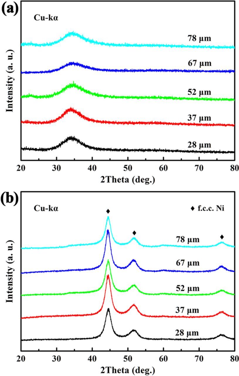
Figure 1. XRD patterns of (a) the as-spun Mg59Ni25La16 ribbons in various thickness ranging from 28 to 78 μm and (b) the corresponding dealloyed samples.
Formation of particles
The ribbons become totally particles after ultrasonic-assisted dealloying for 30 min. Figure 2 shows the resulting particles dealloyed from ribbons in various thickness. As indicated by the arrows in Figure 2, the primary ribbon surface is retained as one surface for most particles. Taken the dimension along the thickness direction as the length, and the dimension along the primary ribbon surface direction as the width by assuming a rectangle particle shape. The variations of length, width and the ratio of length to width with thickness are plotted in Figure 2f. The relationship between length and thickness is approximately linear (d = 0.194x + 2.649, R2 = 0.87, R denotes the coefficient of linear correlation). The width has a weak linear relationship with thickness (d = −0.101x + 13.444, R2 = 0.74). The ratio of length to width has a better linearity with thickness (ρ = 0.0442x − 0.552, R2 = 0.95). The ratio increases from ∼0.7 to ∼3.0 as the thickness increases from 28 to 78 μm. It can be seen that the particle shape can be adjusted by changing the ribbon thickness.
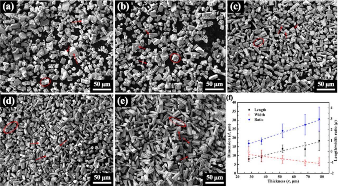
Figure 2. SEM images of the particles fabricated by ultrasonic-assisted dealloying of ribbons in various thickness of (a) 28, (b) 37, (c) 52, (d) 67 and (e) 78 μm for 30 min. (f) The variations of length, width and the ratio of length to width with thickness by assuming a rectangle shape.
The formation of particles should be closely associated with the cracking phenomenon induced by the remarkable volume shrinkage during the dealloying process. In order to investigate the cracking behaviors, ribbons were partly dealloyed without ultrasonic to retain their frameworks. Figure 3 shows the SEM images of the ribbon surfaces after dealloying for only 3 min without ultrasonic. Many cracks can be seen on the top surfaces of these partly dealloyed ribbons. The two-dimensional shrinkage was calculated based on these SEM images, which is shown in Figure 3f. The shrinkage increases as the thickness increases to 52 μm, after which they remain almost unchanged. But in general, the shrinkage has an increasing trend with the ribbon thickness, which may explain the decreasing trend of the particle width with the thickness. Assuming a same shrinkage percentage for three dimensions, the volume shrinkage was calculated. For ribbons in thickness of 52 μm, the volume shrinkage can reach 35%, which is remarkable especially for samples only partly dealloyed for 3 min. The formation of particles should have a close relation with that remarkable volume shrinkage. Besides, the size of the islands isolated by cracks was measured based on these SEM images, which is also shown in Figures 3f. The island size decreases as the thickness increases to 52 μm, after which it is almost independent on the thickness.
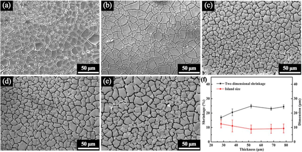
Figure 3. SEM images of the surfaces of ribbons in various thickness of (a) 28, (b) 37, (c) 52, (d) 67 and (e) 78 μm after dealloying for 3 min without ultrasonic. (f) The variations of the two-dimensional shrinkage and island size with thickness.
The cracking behaviors along the thickness direction were further studied. Figures 4a and 4b show the SEM images of the ribbon cross-sections after dealloying for 6 and 12 min, respectively. The ribbon thickness is 78 μm and the dealloying process was performed without ultrasonic in order to keep the integrity of the ribbon. It can be seen that the cracks initiated from the surfaces propagate perpendicular to the ribbon surface. As shown in Figure 4b, when the cracks initiated from the two surfaces reach roughly at the central area of the ribbon, the cracks will be redirected to propagate along the central axis. After dealloying for 12 min, the ribbon thickness is reduced to as low as 58% of the original size, which reconfirms the remarkable volume shrinkage during the dealloying process.
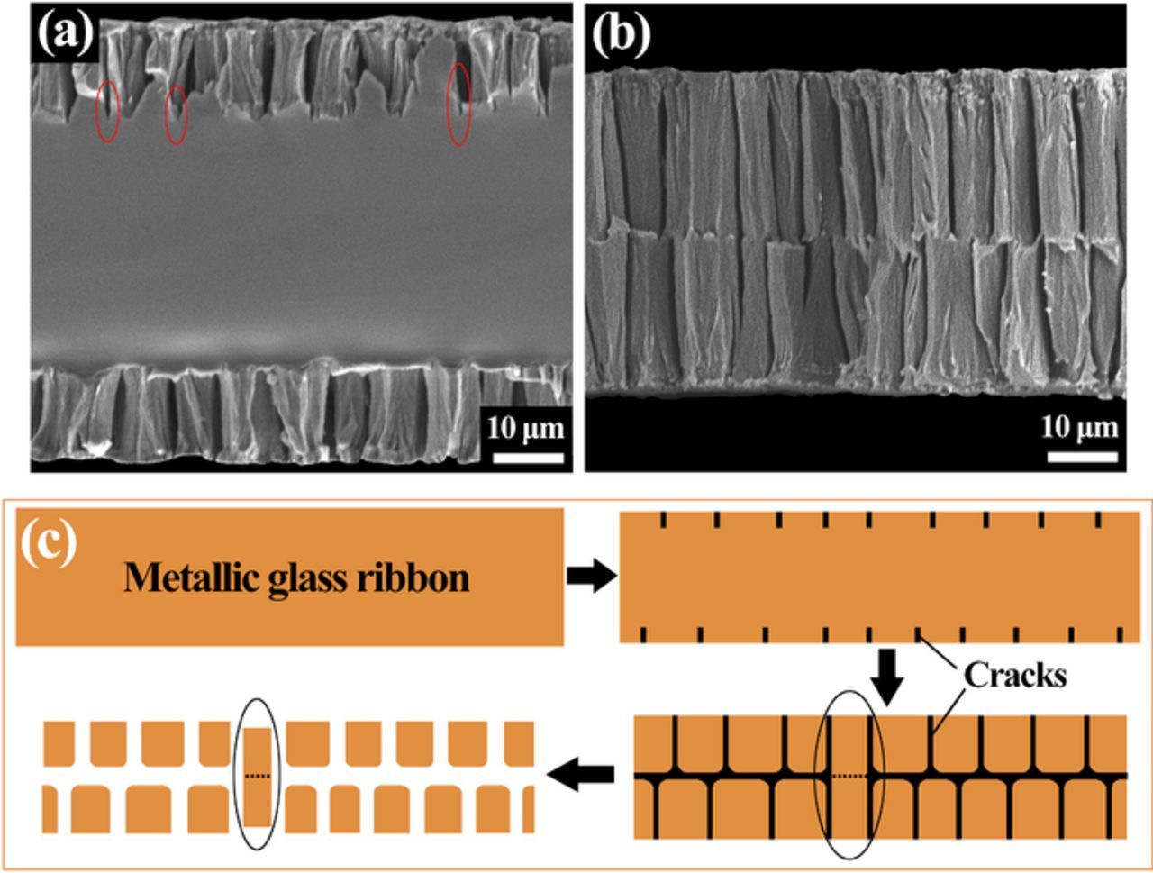
Figure 4. SEM images of the cross-sections of the ribbons in thickness of 78 μm after dealloying without ultrasonic for (a) 6 min and (b) 12 min. (c) Process of particle formation.
According to the particle shape and the cracking behaviors of the metallic glass ribbons, the process for particle formation is proposed, as schematically illustrated in Figure 4c. Firstly, cracks initiate from the two surfaces of the metallic glass ribbons due to the dealloying process. Then, the etching solution will enter the cracks to promote the cracking process and thus the cracks will develop inside. The crack tip is the stress concentrated zone, which will propagate rapidly under the corrosive atmosphere. As indicated by the ellipses in Figure 4a, the cracks usually penetrate into the amorphous substrate and the zones near the crack tips are not dealloyed. The introduction of ultrasonic is to accelerate the cracking of ribbons and thus facilitate the formation of particles. When the cracks initiated from the two surfaces reaching approximately the central area of the ribbon, the stress will concentrate along the two adjacent crack tips, which will redirect the cracks to make them propagate parallel to the central axis. Afterwards, particles are formed with the primary ribbon surface retained as one surface. Sometimes, as indicated by the ellipses in Figures 4c, the cracks initiated from the two different surfaces will coincide in the central axis and the particles cannot be totally fractured to form two secondary particles. The evidence is that some particles marked by ellipses in Figures 2a–2e are obviously not fractured to form two secondary particles. Finally, the particles will undergo further volume shrinkage due to the dealloying process.
Formation of nanoporous structure
It is found that the particles have a uniform nanoporous structure. The ribbon thickness should not influence the nanoporous structure significantly due to the homogeneous structure for all precursor ribbons in different thickness. Thus, ribbons in thickness of 37 μm is taken as an example to investigate the nanoporous structure. Figure 5a shows the nanoporous structure for particles obtained by ultrasonic-assisted dealloying ribbons in thickness of 37 μm for 30 min. As illustrated by the white ellipses in Figure 5a, the np-Ni particles has a ligament-pore structure. TEM was further adopted to characterize the nanoporous structure. The TEM images clearly show a biconnected nanosize ligament-pore structure with dark ligaments and bright nanopores. The ligament size is ∼5–8 nm. As mentioned above, the formation of the nanoporous structure during dealloying is accompanied by a large macroscopic volume reduction, which will result in the cracking of the glassy ribbons and thus lead to the formation of particles (the process for particle formation is illustrated in Figure 4c).
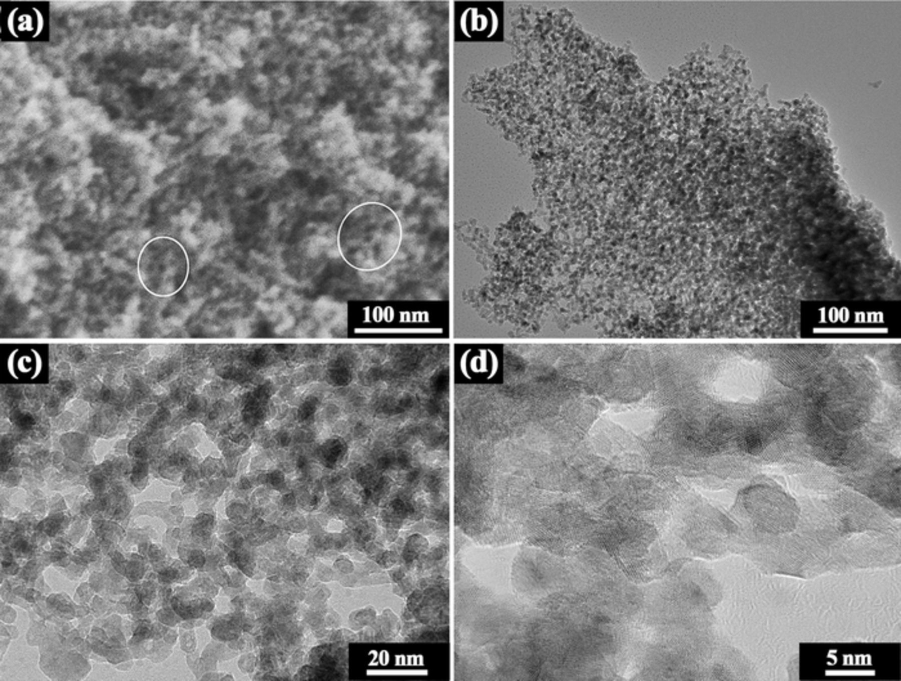
Figure 5. (a) SEM image of the nanoporous structure. (b) Bright-field TEM image of the nanoporous structure. (c) Magnified image of (b). (d) High-resolution TEM image of the nanoporous structure. Samples for these tests were fabricated by ultrasonic-assisted dealloying of ribbons in thickness of 37 μm for 30 min.
The porous structure was studied by the N2 adsorption/desorption isotherm (Figure 6a). The isotherm can be classified as group IV(a) and the hysteresis loop corresponds to type H2(a) according to the IUPAC classification method,42 which is typical for mesoporous materials with diameters in the range of 2–50 nm.42 The BET surface area is 53 m2 g−1, which is comparable to industrial Raney Ni with a BET surface area of 51–65 m2 g−1.43 The corresponding BJH pore size distribution is shown in Figure 6b. It can be seen that the full width at half maximum (FWHM) for the as-fabricated np-Ni is below 2 nm, while the FWHM for industrial Raney Ni exceeds 6 nm.43 Thus, the as-fabricated np-Ni shows a more uniform pore size than industrial Raney Ni. In addition, the as-fabricated np-Ni possesses a smaller pore size (average pore size is 4.0 nm) than Raney Ni (average pore size is above 6 nm).43
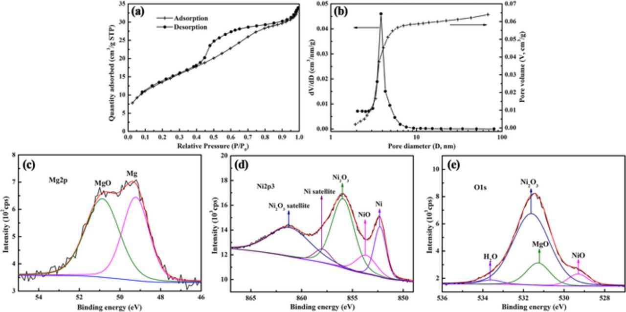
Figure 6. (a) N2 adsorption/desorption isotherm. (b) The corresponding pore size distribution derived from (a). X-ray photoelectron (XPS) spectra of (c) Mg 2p, (d) Ni 2p3/2 and (e) O 1 s. Samples for these tests were fabricated by ultrasonic-assisted dealloying of ribbons in thickness of 37 μm for 30 min.
A continuum model has been proposed to explain the dealloying process for crystalline alloys.2,44–46 In the model, the diffusion of nobler atoms occurs within the same crystal structure without the involvement of any single recrystallization.2,44–46 The continuum model has been successful in explaining the formation of nanoporous structure consisting of a ligament-pore structure by dealloying for crystalline alloys. However, due to the amorphous nature of metallic glasses, the dealloying process in metallic glasses should be different from that in crystalline alloys. A model has been proposed to explain the nucleation and growth processes of nanoporous metals by electrochemical dealloying of metallic glasses.6 According to the model, the surface diffusion of Ni is driven by reduction of total surface and interfacial free energy. Due to the rapid dissolution of less noble Mg and La from the amorphous matrix, the nobler element Ni will agglomerate into crystalline clusters due to energy instability of single atom. In order to further minimize the total surface and interfacial free energy, the neighboring Ni clusters will coalesce and grow to form ligaments by the surface diffusion of Ni. Based on the columnar growth model controlled by surface diffusion of metal atoms, the surface diffusivity of Ni atoms in (NH4)2SO4 solution can be calculated by the expression:9,47
![Equation ([1])](https://content.cld.iop.org/journals/1945-7111/165/3/F207/revision1/d0001.gif)
where t is the leaching time, d(t) is the ligament size at time t, κ is Boltzmann constant, T is the temperature, γ is the average surface tension of the metal, and α is the metal lattice parameter. Based on γNi = 2.00 J m−2 and αNi = 0.35238 nm,8 the Ds of Ni in 1 M (NH4)2SO4 solution is calculated to be 5.86 × 10⁻¹⁸ cm2 s−1, which is very low and is comparable to the reported Ds for noble elements like Pd (1.9 × 10⁻¹⁷ cm2 s−1), Au (2.1 × 10⁻¹⁹ cm2 s−1).48,49 Because a lower surface diffusivity can generate a finer ligament,9,47 the as-fabricated np-Ni shows an extraordinary small ligament size (∼5–8 nm), similar to that of np-Pd (5 nm1) and np-Au (10 nm2–4). The low Ds may be attributed to the weakly acidic environment (pH = 4.91). The fine ligament and pore size of the np-Ni can generate a high specific surface area.
EDS analysis was conducted for particles obtained by ultrasonic-assisted dealloying ribbons in thickness of 37 μm for 30 min and the composition was determined to be Mg0.20Ni99.51La0.29 (at.%). It can be seen that the atomic percentage of the less-noble elements Mg and La is below 0.5%. It has been reported that the bulk composition of Al is normally above 10 at.% for Raney Ni.39 Thus, the np-Ni particles have an advantage of high-purity compared to Raney Ni.
XPS was further conducted to acquire the surface composition and chemical states of the np-Ni. The atomic percentages of Mg, Ni and La on ligament surface are 28.55%, 71.39% and 0.06%, respectively. Compared with the bulk composition obtained by EDS, it is clear that ligament surface is rich in Mg. Mg exists in two forms, i.e. zero-valence Mg and MgO, with peaks positioned at 49.2 and 50.9 eV, respectively (Figure 6c). Furthermore, the molar ratio of MgO to Mg is determined to be 1.21. The Ni 2p3/2 spectrum was used to identify different valence states of Ni on ligament surface (Figure 6d). It is found that Ni is in three chemical states: zero-valence Ni (main peak 852.28 eV, satellite peak 857.94 eV), NiO (853.66 eV), Ni2O3 (main peak 855.92 eV, satellite peak 861.18 eV). It is also found that Ni is mainly in the form of Ni2O3 (69.88 at.%), followed by zero-valence Ni (20.62 at.%) and NiO (9.50 at.%). Because La only accounts for 0.06 at.%, peak fitting was not performed for it and La2O3 was not taken into account when fitting peaks of O 1 s spectrum (Figure 6e). In the O 1 s spectrum, the first peak at 529.31 eV is attributed to NiO. The second peak at ∼531 eV can be distinguished into three peaks: MgO (531.27 eV), Ni2O3 (531.61 eV) and adsorbed water (533.61 eV). It should be noted that the molar ratio of Ni2O3/NiO acquired by O1s spectrum (3.62) is similar to that obtained by Ni 2p3/2 spectrum (3.68), confirming the rational peak fitting herein.
As shown in Figure 7b, a model is constructed to simplify the nanoporous structure of the np-Ni based on the SEM and TEM images. Different from the structure of Raney Ni, which is commonly regarded as an agglomerate of nanoparticles38–40 (Figure 7a), the np-Ni exhibits a ligament-pore structure (Figure 7b). According to the EDS and XPS results, a model for ligament structure is also constructed, as illustrated in Figure 7c. In this model, the ligament has a core of high-purity Ni, covered by a partly oxidized Mg-rich Ni layer. The enrichment of Mg on ligament surface may be for lowering the free surface energy.
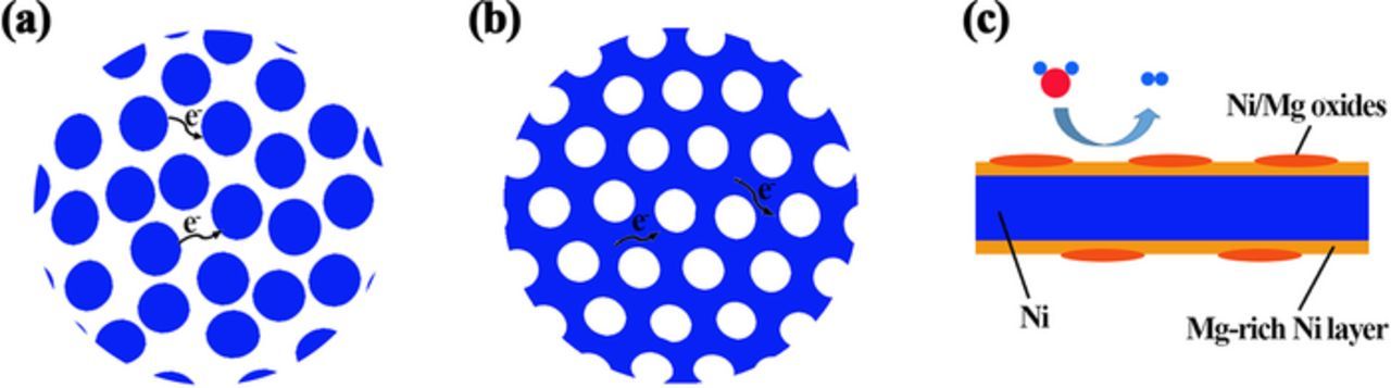
Figure 7. Schematic structures of (a) Raney Ni, (b) the np-Ni and (c) the ligament.
Catalytic performance toward HER
The catalytic performance of the np-Ni particles toward HER was assessed in 1 M KOH solution. The np-Ni particles were obtained by ultrasonic-assisted dealloying ribbons in thickness of 37 μm for 30 min. For comparison, blank Ni foam and commercial Pt/C on Ni foam, were also tested in the same experimental setup. As shown in Figure 8a, compared to blank Ni foam, the overpotential corresponding to 10 mA cm−2 (η10) is greatly reduced from 247 to 45 mV for the np-Ni electrode with a catalyst loading of 7 mg cm−2. η10 can be further decreased by increasing the catalyst loading to 29 mg cm−2, after which η10 almost does not change with the increase of the catalyst loading. Besides, the difference in overpotential between the np-Ni particles (29 mg cm−2) and the commercial Pt/C catalyst (7 mg cm−2) is negligible. Figure 8b displays the Tafel plots derived from the polarization curves in Figure 8a. Tafel slope describes current density (j) enhancement versus η in the Tafel region, and the smaller the Tafel slope is, the faster the j increase with η will be. The np-Ni electrodes with different catalyst loadings share the same Tafel slope of 21 mV dec−1, which is far below the Tafel slope of the blank Ni foam (120 mV dec−1). The lower Tafel slope suggests an improvement of the intrinsic catalytic performance.37 Table I lists the catalytic performance of some representative non-precious metal catalysts.34,50–61 It can be seen that the as-fabricated np-Ni particles show an outstanding catalytic performance toward HER.
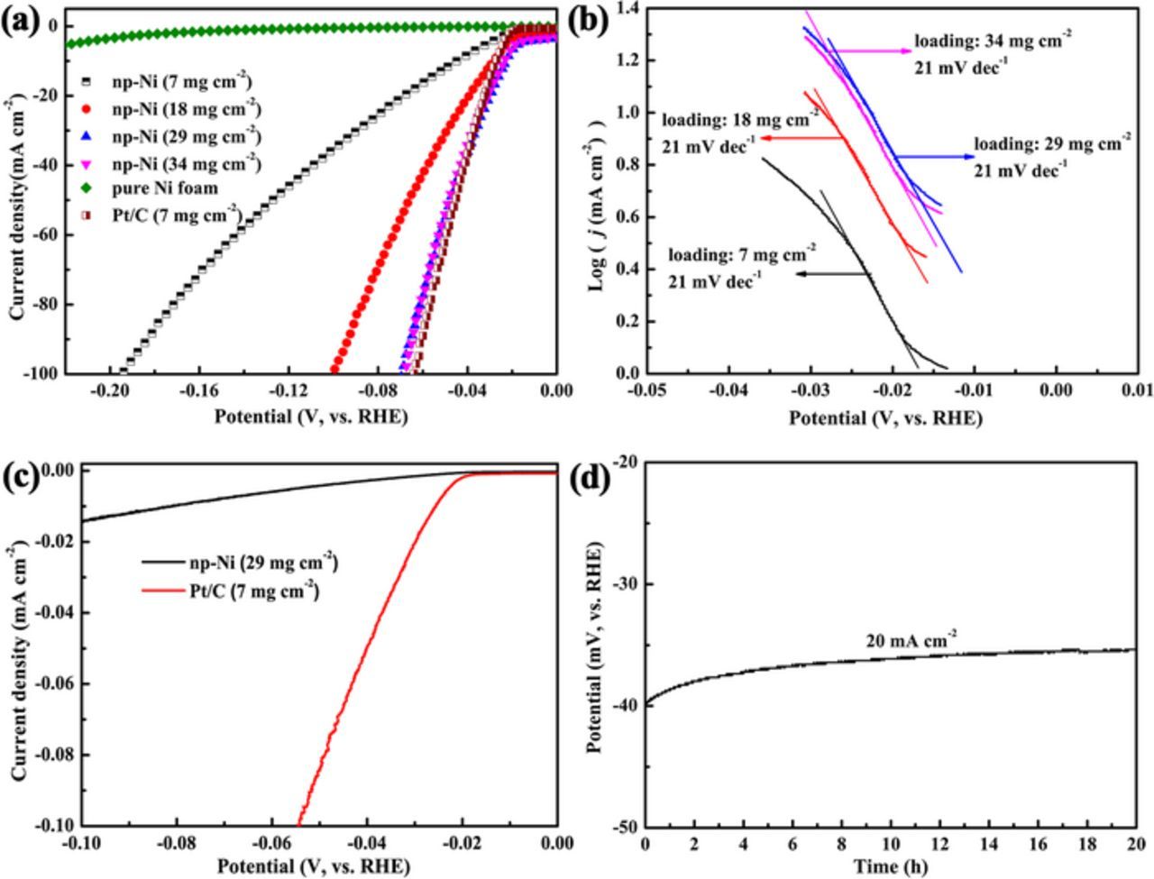
Figure 8. (a) Polarization curves of the blank Ni foam, Pt/C and np-Ni particles with different loadings in 1 M KOH solution. (b) Tafel plots derived from (a). (c) Intrinsic HER activity of np-Ni and Pt/C. (d) Galvanostatic measurement of the np-Ni electrode with a catalyst loading of 29 mg cm−2 at a j of 20 mA cm−2. The np-Ni particles for electrochemical test were fabricated by ultrasonic-assisted dealloying of ribbons in thickness of 37 μm for 30 min.
Table I. Summary of the catalytic performance of some representative non-precious metal catalysts toward HER at room temperature.
| Catalyst | Loading (mg cm−2) | Electrolyte | Overpotential (mV) | Current density (mA cm−2) | Tafel slope (mV dec−1) | References |
|---|---|---|---|---|---|---|
| Np-Ni/NF | 29 | 1 M KOH | 70 | 100 | 21 | This work |
| Raney Ni | \ | 1 M NaOH | ∼103 | 100 | 121 | 34 |
| Ni-WN/CC | 8.9 | 1 M KOH | 155 | 100 | 71 | 50 |
| NiO/Ni-CNT | 11 | 1 M KOH | 95 | 100 | 51 | 51 |
| NiCuP | 6.7 | 1 M KOH | ∼180 | 100 | 47 | 52 |
| NiSe2 | 1.83 | 0.5 M H2SO4 | ∼230 | 100 | 54 | 53 |
| Ni3S2 nanowires | 10 | 1 M KOH | ∼199 | 10 | 106 | 54 |
| Ni-Mo | 3.0 | 0.5 M H2SO4 | 80 | 20 | \ | 55 |
| Ni-Mo | 13.4 | 2 M KOH | 100 | 130 | \ | 55 |
| CoP on Ti | 2 | 0.5 M H2SO4 | 85 | 20 | 50 | 56 |
| Ni2P | 1 | 0.5 M H2SO4 | 180 | 100 | 46 | 57 |
| Co-Ni-P/NF | 6 | 0.5 M H2SO4 | 134 | 100 | 56 | 58 |
| Co-P NW/NF | 6 | 0.5 M H2SO4 | 247 | 20 | 118 | 58 |
| Co-30Ni-B | 2.1 | 1 M NaOH | 233 | 100 | \ | 59 |
| CoS-P/CNT | 1.6 | 0.5 M H2SO4 | 109 | 100 | 55 | 60 |
| Mo2C/CNT | 2 | 0.1 M HClO4 | ∼150 | 10 | 55.2 | 61 |
Electrochemically active surface area (ECSA) is important for redox reactions on electrode surface. ECSA per geometric area is defined as roughness factor (RF), which can be calculated by the formula:62
![Equation ([2])](https://content.cld.iop.org/journals/1945-7111/165/3/F207/revision1/d0002.gif)
where CDL is the double-layer capacitance per geometric area, Cs (0.04 mF cm−2) represents the capacitance per geometric area of an atomically smooth planar surface of the material under identical electrolyte conditions.62 CDL can be determined by cyclic voltammetry test in a non-faradaic region.62 The RF values for the np-Ni electrode with a catalyst loading of 29 mg cm−2, blank Ni foam electrode and Pt/C electrode with a catalyst loading of 7 mg cm−2 are 11438, 8 and 1750, respectively. The large RF resulting from the high specific surface area of the np-Ni should greatly contribute to the high catalytic performance. Based on the current per BET surface area, the intrinsic activity of the np-Ni and Pt/C electrodes are compared with each other. The BET surface area of Pt in Pt/C catalyst is 105 m2 g−1, which is supplied by the supplying maker. As shown in Figure 8c, though the np-Ni show good apparent HER activity, the intrinsic activity of the np-Ni is below that of Pt/C.
The HER mechanism in alkaline media consists of the following steps:17,29,50,51
![Equation ([3])](https://content.cld.iop.org/journals/1945-7111/165/3/F207/revision1/d0003.gif)
![Equation ([4])](https://content.cld.iop.org/journals/1945-7111/165/3/F207/revision1/d0004.gif)
![Equation ([5])](https://content.cld.iop.org/journals/1945-7111/165/3/F207/revision1/d0005.gif)
The electron transfer process involved in the Volmer and Heyrovsky reactions can be facilitated by the good conductivity of the np-Ni due to its ligament-pore structure, contributing to the high catalytic activity toward HER. As illustrated in Figures 7a and 7b, during hydrogen evolution reaction, it is obvious that the electron transfer along the conductive ligaments is much easier compared to the electron transfer between particles. In addition, the Volmer and Heyrovsky reactions involve a process for the generation and desorption of OH−. For a NiO/Ni catalyst, it is proposed that NiO sites can facilitate the formation and desorption of OH−.51 Similarly, the oxides included in the np-Ni particles may also facilitate the formation and desorption of OH− and thus facilitate the Volmer and Heyrovsky reactions, leading to an improved catalytic performance.
The stability of the np-Ni electrode with a catalyst loading of 29 mg cm−2 was evaluated by a galvanostatic measurement at a j of 20 mA cm−2 for 20 h (Figure 8d). The overpotential stays stable, even slightly decreases with the prolongation of time, suggesting a good stability toward HER. For Raney Ni, its catalytic performance will be declined after a long-time electrolysis due to the dissolution of residual Al/Zn in caustic solutions.21,35–37 However, for the as-fabricated np-Ni particles, there is only a small amount of residual elements of Mg and La, and the residual elements are chemically stable in alkaline media, generating a good catalytic stability. Besides, the ligament-pore structure may contribute to the catalytic stability of the np-Ni particles. The ligament-pore structure can provide a firm support which resists recrystallization and sintering to some extent during HER, resulting in a stable catalytic performance.
In summary, the high activity of the np-Ni can be attributed to 1) high purity which can provide more active Ni sites, 2) a large electrochemically active surface area with the roughness factor reaching 11438, 3) high conductivity due to the ligament-pore structure, and 4) the coverage of Ni/Mg oxides on ligament surface. Furthermore, the good catalytic stability is attributed to the chemical stability of Mg and La in alkaline media and the firm support of the ligament-pore structure.
Conclusions
- (1)Homogeneous np-Ni particles were synthesized by ultrasonic-assisted dealloying of Mg-Ni-La metallic glass ribbons in (NH4)2SO4 aqueous solution. The particle length and the ratio of length to width show good linear relationships with the ribbon thickness. Particles with different shapes can be fabricated by adjusting the ribbon thickness. The formation of particles is associated with the cracking of ribbons induced by the remarkable volume shrinkage. The introduction of ultrasonic is to accelerate the cracking process.
- (2)The np-Ni particles show a ligament-pore structure. The ligament diameter is ∼5–8 nm. The nanopores show a narrow size distribution with an average size of 4 nm. The ultrafine structure generates a high specific surface area of 53 m2 g−1, leading to a high roughness factor of 11438.
- (3)The atomic percentage of the less-noble elements Mg and La after dealloying is below 0.5%, suggesting a high purity of the np-Ni particles. The ligament structure was analyzed. It is found that the ligament has a core of high-purity Ni, covered by a partly oxidized Mg-rich Ni layer.
- (4)For hydrogen evolution reaction, the np-Ni particles can deliver a current density of 100 mA cm−2 at a small overpotential of only 46 mV with a low Tafel slope of 21 mV dec−1. In addition, the np-Ni particles show a long-term stability upon continuous galvanostatic electrolysis for up to 20 h without any degradation, which may be attributed to the chemical stability of Mg and La in alkaline media and the firm support of the ligament-pore structure.
Acknowledgments
This work was supported by the National Natural Science Foundation of China (grant Nos. 51771008 and 51571005), the Fok Ying-Tong Education Foundation for Young Teachers in the Higher Education Institutions of China (grant No. 142008), and the Beijing Natural Science Foundation, China (grant No. 2172034).
ORCID
Tao Zhang 0000-0002-9561-3242