
Abstract
This review article presents a state-of-the-art survey on timber-concrete composite (TCC) bridges. It starts with a presentation of a sample of relevant TCC bridges, offering a global perspective on the use of this type of bridge. The number of TCC bridges has clearly increased in the past few years, and some of the reasons for this trend are explored. Next, an extensive literature review is presented regarding the most significant technological innovations and recent developments in the application of TCC structures to bridge construction. Firstly, the engineering specificities and the advantages of TCC bridge structural systems are enumerated. Afterwards, the importance of proper mechanical connection for optimal performance of TCC structures is explained, and a thorough description of the connection systems suitable for bridge construction is provided. Some research into the structural behavior of TCC bridges under service conditions is then presented and discussed. Finally, possible areas of future research regarding the development of TCC bridges are suggested.
Download PDF
Full Article
Timber-Concrete Composite Bridges: State-of-the-Art Review
João N. Rodrigues,* Alfredo M. P. G. Dias, and Paulo Providência
This review article presents a state-of-the-art survey on timber-concrete composite (TCC) bridges. It starts with a presentation of a sample of relevant TCC bridges, offering a global perspective on the use of this type of bridge. The number of TCC bridges has clearly increased in the past few years, and some of the reasons for this trend are explored. Next, an extensive literature review is presented regarding the most significant technological innovations and recent developments in the application of TCC structures to bridge construction. Firstly, the engineering specificities and the advantages of TCC bridge structural systems are enumerated. Afterwards, the importance of proper mechanical connection for optimal performance of TCC structures is explained, and a thorough description of the connection systems suitable for bridge construction is provided. Some research into the structural behavior of TCC bridges under service conditions is then presented and discussed. Finally, possible areas of future research regarding the development of TCC bridges are suggested.
Keywords: Bridge decks; Composite bridges; Timber-concrete composite structures; Connection systems; Timber construction
Contact information: Department of Civil Engineering, University of Coimbra, Rua Luís Reis Santos – Polo II, 3030-788 Coimbra, Portugal; *Corresponding author: joao.nar@hotmail.com
INTRODUCTION
Nearly all Timber-Concrete Composite (TCC) bridges are either slab bridges or girder bridges with the composite structure applied to the deck. Actually, due to the combined action, the girders are considered to be a part of the deck in TCC girder bridges. These TCC bridge decks are formed by three resisting components: a reinforced concrete slab on top of a group of longitudinally placed timber beams, with the slab and beams joined together by a connecting system. This definition excludes timber decks covered by a concrete layer solely for timber protection or other nonstructural purposes.
TCC structures, and particularly TCC bridges, made their first appearance in the 1930s in the USA (Richart and Williams 1943) when a shortage of steel drove builders to use other available structural materials (Van der Linden 1999). In the following decade, TCC bridges had already become common in the USA (Duwadi and Ritter 1997). In the 1950s, TCC structures started to be applied to bridge construction in Australia and New Zealand (Cone 1963; Nolan 2009). However, until quite recently, TCC bridges were ignored in most parts of the world. Actually, it was only in the beginning of the 1990s that TCC bridges emerged in Europe, e.g., Finland, Switzerland, France, Germany, and Austria (Pischl and Schickhofer 1993; Natterer 1998; Aasheim 2000; Flach and Frenette 2004), and also in Brazil (Calil Jr 2006). In the USA, over the last few years, and after a period in which they almost fell into disuse, there appears to be a rebirth of interest in timber bridges in general (Wacker and Smith 2001) and in TCC bridges in particular (Weaver et al. 2004; Balogh et al. 2010).
Many TCC bridges have been investigated due to their innovative or unique characteristics. However, a comprehensive state-of-the-art review of this type of bridge is still lacking. Such a review can provide an important base for practicing engineers or research projects. This article aims to present a literature review of TCC bridges that (i) includes an overview of their use in different geographical areas and climates and (ii) examines different issues related to this type of structural solution, such as its main engineering characteristics, design approach, connection systems, and structural behavior under service conditions.
WORLWIDE USE
The present analysis is based on a sample of 75 TCC bridges. We believe this sample is representative of the total number of TCC bridges existing worldwide, which, according to Balogh et al. (2012), is higher than 100.
In the USA, the development of TCC solutions for bridge construction was promoted by the University of Washington (Seiler and Keeney 1933). The objective of this project was to combine timber and concrete to build bridges that (i) were cheaper than reinforced concrete bridges, (ii) had a longer service life than timber bridges, and (iii) whose construction would require no special equipment. Construction soon spread to other U.S. states, such as Oregon and Delaware, where some are still in use, with low maintenance costs (McCullough 1943).
In South America, TCC bridges were only built in Brazil, although they have been investigated in other countries, such as Chile (Cárdenas et al. 2010) and Argentina (Astori et al. 2007). In Brazil, TCC bridges were constructed for vicinal roads under a research program on timber bridges promoted by the University of São Paulo (Calil Jr 2006). The main goal of this program was to design short span bridges featuring (i) a competitive cost and (ii) a durability that could be positively compared with that of other structural materials. The good results in terms of overall performance of these bridges suggests that there might be a market for TCC bridges in Brazil, especially in vicinal or secondary roads (Soriano and Mascia 2009).
In Oceania, the first TCC bridges were probably built by the U.S. army in the 1950s (Nolan 2009). They were an important technological improvement over timber bridges, whose construction was locally well established (Yttrup 2009). More recently, research programs were launched by forest authorities to promote the construction of TCC short span bridges with local roundwood species, leading, for example, to the addition of a specific chapter to the Timber Bridge Manual, supported by the Roads and Traffic Authority of New South Wales (RTA-NSW), Australia.
In Northern Europe, namely Finland, the “Nordic Timber Bridge Project” – a comprehensive research program of Finland and the Scandinavian countries, stimulated TCC bridge construction. This project aimed to encourage the construction of timber bridges as an alternative to reinforced concrete and steel bridges. The Finnish team was in charge of the sub-project on the specific topic of TCC bridges because the first TCC bridge in the region had been built in Finland before the beginning of the Project (Aasheim 2000).
In Western Europe, following the construction of the first TCC bridge in Switzerland (Natterer et al. 1998), other countries, such as Austria, France, Germany, and Luxembourg, adopted this type of bridge. According to Meierhofer (1996), TCC bridges are rather successful in this region not only because local public authorities are genuinely interested in bridges incorporating timber, but also because, when compared to timber bridges, TCC bridges have the important advantage of not requiring a strong chemical protection, which can be harmful to the environment.
In Southern Europe, as in other geographic regions, TCC bridges are extremely rare, with only one identified in Portugal (Dias et al. 2011) and another in Italy (RUBNER Ingenieurholzbau S.p.A. no date). The lack of awareness of this structural solution among engineers and architects has undoubtedly hindered the introduction of TCC bridges in some construction marketplaces (Rodrigues et al. 2010).
Figure 1 groups by construction date the sample of TCC bridges collected for the present article, revealing that more than 85% were built in the last twenty years, and more than 50% were constructed from 2000 to 2010.

Fig. 1. Construction date of the TCC bridges considered in this study
This recent increase in TCC bridge construction is explained by (i) their cost competitiveness, (ii) their environmental friendliness, and (iii) recent technological innovations regarding the application of TCC structures in bridges. Currently, civic authorities, industry, and the general public are mainly looking for innovative solutions that are low cost and sustainable, requirements that are fulfilled by TCC bridge structural systems. Actually, TCC bridges are generally accepted as competitive structures, especially in respect to environmental sustainability factors (Meierhofer 1993; Natterer 2002; Steinberg et al. 2003; Gutkowski et al. 2004), and for their huge field of existing applications.
ENGINEERING CHARACTERISTICS
TCC Structural Systems (Decks)
As previously mentioned, it is the composite structure of the deck that generally endows a composite character to TCC bridges. Two basic types of TCC decks are usually found: slab decks and T-beam decks.
Composite slab decks are built by casting a reinforced concrete layer over a timber layer, usually formed by solid circular girders (log beams) or solid rectangular girders (sawn lumber beams), arranged side-by-side with their axes parallel to the longitudinal axis of the bridge, see Fig. 2(a) and (c). The span of this type of deck is constrained by the diameter and height of the tree trunks. Clear spans of 5 to 15 m are the most common. Nevertheless, in composite slab decks, the timber layer can also be made of glulam. Although this option appears to be structurally inefficient and less competitive, it can make some sense, particularly when there are clearance constraints (under the bridge) or whenever glulam is competitive when compared with other locally available timber products.
In composite slab decks, the timber layer also plays the role of stay-in-place formwork when casting concrete, see Fig. 2(b). The reinforcement of the concrete slab consists of a steel mesh with equal cross section areas in the transverse and longitudinal directions. In this type of deck, the reinforcement is mainly required to ensure the slab durability, e.g., to resist concrete cracking.

Fig. 2. Composite slab deck (Campus II USP Bridge, Brazil – 12 m span): (a) craning of log beams into position; (b) concrete placement; (c) bottom view
A reinforced concrete slab casted on equally spaced timber girders (Fig. 3a, d), forms composite T-beam decks. This type of deck usually uses manufactured glulam beams available in standard widths ranging from 6 to 24 cm and whose depth and length are limited essentially by transportation and handling issues. Hence, composite T-beam decks with glulam beams are capable of much longer clear spans than slab decks, being most commonly used for spans of 10 to 30 m. In composite T-beam decks, the structural function of the slab is similar to that in steel-concrete composite bridges – a steel reinforcing mesh must resist the transverse bending moments. Top and bottom steel meshes are often used. In the illustrated example in Fig. 3(c), both the slab reinforcement and the connection system (X-connectors) can be seen.
Fresh concrete has almost no strength and stiffness. Hence, TCC decks require a temporary bearing structure, called false work, until the concrete hardens. This will ensure acceptable deflections, indispensable for serviceability, performance, and aesthetics (Fig. 3b). Actually, the design of TCC decks is usually governed by deflection, i.e., by serviceability limit states. Eurocode 5, Part 2 (CEN 2004c) defines the limit values of l/400 to l/500 for deflections of timber beams in road bridges, where l is the bridge span.
Recently, a new type of composite deck was developed (Limam et al. 2006), with pairs of parallel timber beams facing each other a short distance apart, forming a double-T. When the concrete is casted, it partially fills the upper space between the two beams. This system was used in only one of the TCC bridges identified in this study.

Fig. 3. Composite T-beam deck (Quiaios Bridge, Portugal – 15 m span): (a) glulam beams; (b) formwork and false work; (c) reinforcement and X-connectors; (d) bottom view
As previously mentioned, solid timber and glulam are the two main types of timber products used in TCC bridges. Table 1 shows typical values of their mechanical properties and density. A concrete with characteristic compressive cylinder strength between 30 and 40 MPa (C30/37 to C40/50 according to Eurocode 2 (CEN 2004a)) is recommended for durability reasons, and characteristic yield strength values of 400 to 500 MPa are common for reinforcement. However these two ranges may vary from country to country according to local practice.
Table 1. Mechanical Properties of Timber Products

Deck Support Systems
Two basic design conditions must be considered to ensure the structural efficiency of TCC bridges: (i) the neutral axis of the composite cross section should be located close to the timber-concrete interface at flexural failure, and (ii) the connection system has to be sufficiently strong and stiff to resist the shear forces developing between the two materials. The former condition is essential to make the most of the strength and stiffness properties of the materials – timber under tension and concrete under compression. Girder bridges with simply supported spans easily satisfy it and, actually, most TCC bridges in the sample collected for this study (about 85%) are girder bridges with single or multiple simply supported spans. Continuous beam systems can also be used, but negative bending moments at the supports require specific detailing.
Although simplicity of construction is one of the main advantages of TCC girder bridges, the design of the supports requires special attention because the vertical reactions produce high bearing compression stresses perpendicular to the grain of the timber elements, which is the direction with lowest uniaxial compressive strength. A common method to solve this problem is to decrease the stress in timber by providing a bearing area large enough to adequately transfer the loads, for instance, interposing elastomeric or steel bearing elements.
Rautenstrauch et al. (2010) reported the use of elastomeric bearings, in which an elastomer is confined by steel plates, see Fig. 4(a). Dias et al. (2011) proposed a U profiled steel element, where the timber elements fit, which is then placed over an elastomeric bearing pad, see Fig. 4(b). Elastomeric elements “absorb” some deformations due to shrinkage and creeping. Another method to increase the support capacity of TCC decks is to use reinforced concrete elements to transmit the reactions. In this case, the timber beam ends are replaced by reinforced concrete elements that provide the support bearing. Bathon et al. (2006a) proposed and investigated a solution where the timber beam ends are joined to these reinforced concrete elements with the same continuous HBV connector used to link the beams with the reinforced concrete slab along the span (Fig. 4c) – the HBV connector is an expanded metal plate, one half of which is glued into a slot made in the timber while the other half is within the concrete element. Engineers of the RTA-NSW investigated a similar solution. In this case, the log beams forming the timber layer penetrate the end-reinforced concrete diaphragms (Fig. 4d). To improve the connection with this diaphragm, a steel channel is applied to the full depth of its flanges to the upper face of each log beam.

Fig. 4. Different support systems (1 – reinforced concrete slab; 2 – timber beam; 3 – steel elements; 4 – elastomeric element; 5 – HBV-connector; 6 – steel channel PFC 150): (a) elastomeric bearing; (b) steel bearing; (c) and (d) reinforced concrete bearings (all dimensions in meters)
Main Advantages of TCC Decks
A TCC bridge deck has a much higher bending strength and lower deflections than that of a timber (non-composite) deck with similar dimensions (Ceccotti 2002; Weaver et al. 2004), which are important mechanical advantages of TCC structures. Additionally, the reinforced concrete slab of the TCC deck assures continuity in the longitudinal and transverse directions and the transverse rigidity required to distribute the live load amongst the timber elements (Simon et al. 2008).
The arrangement of the elements in TCC decks also offers important durability advantages when compared with timber decks. The presence of a reinforced concrete slab on top of the timber elements provides an effective protection to the timber beneath, contributing significantly to its durability (Mascia and Soriano 2004), because it ensures water runoff, limiting the contact of timber elements with water, and reduces the moisture variation in the timber elements. In order to protect the lateral beams from rain, the angle between the horizontal plane and the plane defined by the outermost edges of the bottom face of these beams and of the concrete slab overhang should not be less than 60º. Moreover, to avoid any moisture transmission from concrete to timber elements, namely during concrete curing, a waterproof painting of all timber parts in contact with concrete should be provided (Fjellström et al. 2002).
EN 335 (CEN 2013) defines use classes to represent the service conditions to which timber products can be exposed. Use class 5 is the most severe and use class 1 is the least severe; bridge deck service conditions correspond generally to use classes 2 and 3. Use class 3 should be considered for timber in non-composite decks (except covered bridges) because it is not adequately protected, i.e., it is either continually exposed to weather or protected from weather but subjected to repeated wetting. Due to the arrangement of the components, timber in TCC decks is usually use class 2 because, even though it is not weather exposed, a high environmental humidity may cause its occasional wetting. Furthermore, the reinforced concrete slab offers direct sun protection to the timber elements and provides a wear-resistant surface that hinders the direct contact between vehicle wheels and timber elements.
At the same time, TCC bridge decks share the benefits of timber, which are considerable. Timber is a sustainable building material – a natural and renewable resource, whose production requires small amounts of non-renewable energy (Petersen and Solberg 2002; Falk 2009). Besides, timber is a carbon store that can decrease the environmental impact of construction, through its carbon sequestration mechanism, depending on its end-of-life treatment (Bouhaya et al. 2009).
Two small-span bridges of reinforced/prestressed concrete were compared by the authors with similar TCC deck bridges, using an integral life-cycle methodology comprising environmental, economical, and social assessment (Rodrigues et al. 2013). This analysis showed that TCC solutions cause less environmental impact and are cost-competitive. Other authors, e.g., Meierhofer (1993), Lee (1999), and Mettem (2003), have also argued that TCC structures can be cost-competitive alternatives to other structural solutions.
Moreover, timber is a structural material that combines high bending strength with low weight, which is an important advantage over other structural materials (Ceccotti 2002), allowing the construction of easily workable and handled bridge decks. This enhances the development of prefabricated off-site solutions, which are highly competitive (Clouston et al. 2005).
Recent efforts have been made to develop prefabricated TCC decks for bridge applications, adding to all the advantages of construction in situ, such as a shorter erection time, cost reduction, a better working environment, and quality control (Yeoh et al. 2011). Bathon et al. (2006b) developed a wholly prefabricated TCC deck, transported to site fully assembled and primarily intended for replacing the unprotected deck of pedestrian timber bridges when their life cycle terminates. The engineering team at RTA-NSW developed the aforementioned prefabricated TCC system for bridge decks produced in small size modules, which are easily transported and joined together on site. This system was applied in some of the bridges collected for this article.
TECHNICAL CODES AND ANALYSIS METHODS
Only the USA, Australia, and EU have technical codes addressing the design of TCC bridges. In the USA, the AASHTO Standard Specifications for Highway Bridges referred to TCC bridge solutions in its 1944 edition (AASHO 1944). In Australia, chapter 7 of the Timber Bridge Manual (RTA 2008) is fully devoted to the design, construction, and maintenance of TCC bridges. In the EU, section 5.3 of Eurocode 5, Part 2 (CEN 2004c) mentions, rather briefly, the design of TCC elements of bridges.
The design of TCC structures must take into consideration the deformation of the connection system, responsible for the commonly called partial composite action, and the consequent slip at the timber-concrete interface. Hence, the Euler-Bernoulli hypothesis for beam bending is obviously not valid for TCC beams.
Linear-elastic methods, i.e., assuming that all materials (timber, concrete, and connections) are linear-elastic, are widely used in the analysis and design of TCC structures, including bridges (Dias et al. 2011). Although these methods give sufficiently accurate results for most practical applications (Van der Linden 1999), particularly for structures carrying low-intensity loads, e.g., floors, some connection systems can only be properly addressed with a nonlinear analysis. Actually, in structures subjected to high loads, such as bridges, the stresses at the connection system can be so high that the composite structural behavior is governed by the connection stiffness and strength. In this case, an accurate solution may require a nonlinear analysis (Dias 2012).
For the linear-elastic analysis of TCC beams, Ceccotti (2002) recommended the linear-elastic method included in Annex B of Eurocode 5, Part 1-1 (CEN 2004b) for timber-timber composite beams with flexible connections. The full derivation of this method can be found, for example, in STEP lecture B11 (Kreuzinger 1995). This method (gamma method) is operated under the following assumptions: the timber and concrete are connected to each other by mechanical fasteners with slip modulus K and constant or linearly varying spacing s, according to the shear force value, between a lower bound smin and an upper bound smax, with smax ≤ 4smin, and the load is acting perpendicular to the beam axis, with a sinusoidal or parabolic bending moment field. To account for the partial composite action, the gamma method makes use of an effective bending stiffness, (EI)ef, which considers the connection stiffness through a composite coefficient, γ, ranging from 0 for no composite action to 1 for full composite action.
The example in Fig. 5 highlights two extreme situations for a simple supported beam: (a) no connection between the elements (γ = 0) and (b) perfect connection between the elements (γ = 1). In the former case, the slip at the interface is free, and the two components independently resist the transverse loading, with global bending stiffness given by the sum of the elementary stiffnesses. In the latter case, the two components act together – there is no slip at the interface, the top element is mostly under compression, the bottom element under tension and the global bending stiffness is much higher than the sum of the elementary stiffnesses, which means that the deflection is much lower. Practical cases lie somewhere between these two extremes. This illustrates the utmost importance of the mechanical behavior of the connection system for the behavior of composite structures, including stress and deformation states (Dias 2005).
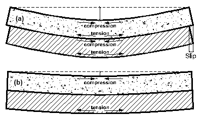
Fig. 5. Simply supported beam under transversal loading: (a) no composite action; (b) full composite action
CONNECTION SYSTEMS
Mechanical Properties of Connection Systems
One of the major challenges facing TCC structures is the design of the connection system. To characterize the mechanical behavior of a connection system, it is necessary to consider its stiffness, strength, and ductility. Moreover, because bridges are subjected to cyclic loading due to traffic oscillations, the possible degradation of the mechanical properties of connection systems caused by fatigue must also be considered. For each different type of connection, these properties can be experimentally measured through shear tests (Table 2).
The stiffness of a connection system, given by its slip modulus K, influences the level of composite action, i.e., the value of γ. Alternatively to K, the smeared slip modulus, k = K / s, i.e., the slip modulus per unit length, can be used (Van der Linden 1999; Ceccotti 2002), particularly to compare the effectiveness of different connection systems.
With the increase of k and, consequently, of the level of composite action, (EI)ef also increases, tending asymptotically to a maximum (EI)ef,max as k approaches infinity, as illustrated in Fig. 6, for a practical case with a concrete layer with cross-section of 1000 x 200 mm, a glulam beam with cross-section of 200 x 800 mm, and Econcrete=3Etimber. This figure shows that (EI)ef also tends to a minimum (EI)ef,min ≈ (EI)ef,max/4 when k approaches zero. This means that above a certain level, the increase of the connection stiffness becomes almost useless, having a minor effect on the effective bending stiffness. Also, below a certain value of the connection stiffness, composite action becomes negligible.

Fig. 6. Relationship between effective bending stiffness of a TCC beam and the smeared slip modulus of the connection
The connection strength, given by its ultimate load Fu, limits the longitudinal shear between timber and concrete. This property is particularly important in bridges, as opposed to other structures such as floors, due to the high concentrated traffic loads.
The ductility of a connection, considered by its ultimate deformation capacity δu, is also an important mechanical characteristic – it reduces the risks of a brittle failure (Clouston et al.2005), allows for load redistribution among the fasteners, and increases the load-bearing capacity and ultimate deformation capacity of the composite structure. Because the maximum slip in the timber-concrete interface is inherently small, the ultimate deformation capacity of the connections is generally adequate. However, this should always be checked (Dias and Jorge 2011).
Types of Connection Systems
Research on connection systems suitable for TCC bridge construction dates back to the 1940s (McCullough 1943) and 1970s (Pincus 1970). However, during the last few years, a significant increase in research on this topic has occurred, with a wide range of connection systems specifically for bridge construction presently under investigation in different parts of the world. These investigations include shear tests of TCC connection systems and, often, bending tests of TCC beam or panel prototypes incorporating such connection systems.
The connectors can be metal fasteners, notches in the timber or a combination of the two. More recently, some authors started to investigate the use of gluing technology in connection systems applied to bridges. Regarding their spatial distribution, connectors can be categorized as either discrete or continuous.
Discrete connection systems with metal fasteners are the most generalized. Mascia and Soriano (2004) studied the mechanical performance of connection systems composed of nails and screws (Fig. 7a, b), respectively, and concluded that nails provide a satisfactory and efficient connection, which is easier to apply and cheaper than screws. Astori et al. (2007) investigated the use of screws together with steel springs (Fig. 7c), to reduce stress concentration around the screws, finding them suitable for bridge applications. An investigation carried out at the University of São Paulo (Molina and Calil Jr 2008), studied connection systems with dowels fastened in holes drilled at an angle of 90º to the timber grain (Fig. 7d). At the University of NSW, Australia, Benítez (2000) investigated two other types of discrete connection systems with metal fasteners, circular hollow sections together with screws (CHS) and universal column sections (UCS) (Fig. 7e, f); both have shown a high stiffness and load-bearing capacity. Simon et al. (2008) from Bauhaus-University Weimar, Germany, also developed a stiff connection. It consists of a horizontal steel plate (HSP) inserted into the timber and welded studs on the concrete side (Fig. 7g). Two different versions of this connector were investigated: the first had two studs welded to 2- and 3-cm-thick steel plates, while the second had four studs plus a 5-cm trapezoidal rim within the timber welded to a 2-cm-thick steel plate on the concrete side. Increasing the thickness of the plate from 2 to 3 cm increased the load-bearing capacity of the connector. However, no load increase was verified for higher thicknesses. The specimens with two studs showed ductile deformation, while the others exhibited brittle fracture. Tommola et al. (1999) investigated the possibility of using rebars to produce X-connectors (Fig. 7h), consisting of rebars placed crosswise and glued into 45º inclined holes drilled in timber (Dӧhrer and Rautenstrauch, 2006b; Molina and Calil Jr. 2008; and Aldi and Kuhlmann 2010). These connections have exhibited good ductility and a quite acceptable slip modulus and load-bearing capacity. Miotto and Dias (2008) investigated connection systems made of rebars of two different diameters glued into timber holes drilled at a 45º angle to the timber grain (Fig. 7i). The results regarding the efficiency of this connection system were quite encouraging, with their stiffness being influenced by the diameter of the rebars. This investigation included a connection system with a perforated steel plate (PSP) inserted and glued into the timber (Fig. 7j). Although this connection system was stiffer than the connection with rebars, it exhibited a brittle fracture. A similar connection system, a “T” steel plate with an end plate (TSP) (Fig. 7k), was developed at Helsinki University of Technology (Mäkipuro et al. 1996). Its indoor and outdoor mechanical behaviors were compared, showing that, due to weathering, it becomes brittle and there is an average 84% reduction of its load-bearing capacity.
Discrete connection systems with metal fasteners are often combined with notches cut into the upper surface of the timber beams, which get filled when concrete is poured. Mäkipuro et al. (1996) tested connection systems made with rebars glued into timber holes drilled at an angle of 45º to the timber grain together with notches (Fig. 7l). The mechanical properties of these specimens were much better than those of similar specimens without notches. Moreover, because the production of these notches is easy and cheap, their use is recommended. Yttrup (2009) combined notches with dowels (Fig. 7m), and compared this connection system with only timber notches or only dowels, concluding that the most effective design is the one combining notches and dowels. There were other tests performed on connection systems made only of notches. This is the case of the grooved connection (Fig. 7n), tested by Dӧhrer and Rautenstrauch (2006b), revealing a satisfactory mechanical behavior, including ductile failure. This connection was also studied at the University of Stuttgart, Germany (Aldi and Kuhlmann 2010), confirming the previous satisfactory results with the exception of the mode of failure, which was brittle and due to a crack that appeared between the concrete notch and the upper edge of the timber.
Continuous connection systems such as metal plates can also be used. Bathon et al. (2006b) at the University of Wiesbaden, Germany, investigated the HBV connector previously mentioned when describing the support systems (Fig. 7o). They tested specimens with one, two, and three rows of metal plates and concluded that the group effect increases both the strength and stiffness of the connection system. The connection showed a ductile behavior, with failure always occurring at the metal plates.
The third type of connection systems are the glued connections: because they present a continuous distribution, the shear forces on the timber-concrete interface are evenly distributed, avoiding the local stress concentrations which are inevitable with discrete connections. Moreover, glued connections ensure a rigid connection between timber and concrete, i.e., no slip is observed at their interface. On the other hand, glued connections introduce the possibility of brittle failure.
Brunner et al. (2007) investigated the behavior of glued connections using a “wet” production process in which fresh concrete is poured onto still wet adhesive. Although the excellent mechanical characteristics previously mentioned were confirmed, the authors concluded that the use of “wet” glued connections is still not recommended because it is difficult to ensure an adequate thickness of the glue layer, namely in the concrete pouring areas. A more common use of glued connections is the assembling of the timber beams to a precast concrete slab (Le Roy et al. 2009; Ben Mekki and Toutlemonde 2011). This “dry” glued connection avoids the problem of the glue layer thickness, but it can only be applied to prefabricated TCC structures.
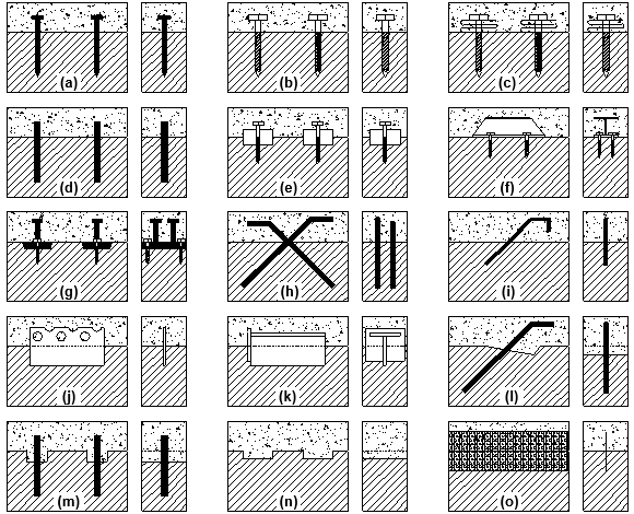
Fig. 7. Connection systems (left – longitudinal section, right – cross section): (a) nails; (b) screws; (c) screws + springs; (d) dowels; (e) CHS + screws; (f) UCS; (g) HSP + studs; (h) X-connector; (i) rebars; (j) PSP; (k) TSP; (l) rebars + notches; (m) dowels + notches; (n) grooved connection; (o) HBV
Table 2. Mechanical Properties of Connection Systems (Mean Values)

Connection System Fatigue
Some of the connection systems mentioned above were subjected to fatigue tests by applying repeated loading cycles (Table 2). One of the first studies on the fatigue of TCC connection systems, in this case the X-connector, was conducted at the Helsinki University of Technology (Mäkipuro et al. 1996). The results showed that under cyclic loading, the steel bars soon began to lose their strength, and the initial slip grew up to 2.5 mm, endangering the composite action. In an attempt to enhance the behavior of this connection system, Tommola et al. (1999) combined the X-connector with notches, see Table 2(h), obtaining a 30% improvement in connection strength and a significant increase in connection stiffness. Fatigue tests on X-connectors were also carried out by Molina and Calil Jr. (2008) and Aldi and Kuhlmann (2010).
Weaver et al. (2004) performed fatigue load cycles on TCC specimens and TCC beams with dowels. Even though there was no reduction of load-bearing capacity or ductility, the stiffness decreased and the midspan deflection increased, indicating fatigue damage, mainly during the first million cycles. The fatigue behavior of dowels was also studied by Molina and Calil Jr. (2008). Benítez (2000) reported fatigue tests on two connection systems: the circular hollow section and the universal column section. Aldi and Kuhlmann (2010) and Balogh et al. (2012) studied the fatigue behavior of TCC specimens with a grooved connection. TCC specimens with horizontal steel plates together with studs and HBV connectors were also subjected to fatigue load cycles (Dӧhrer and Rautenstrauch 2006a; Bathon and Bletz 2010).
Even though a reasonable number of different types of connection systems suitable for bridges have already been investigated, the fatigue behavior of connection systems requires further research because, even though some codes, e.g., Eurocode 1, Part 2 (CEN 2003), provide rules for estimating the fatigue action on bridges, a method to verify the fatigue of the connections in TCC structures is still missing.
STRUCTURAL BEHAVIOR – CASE STUDIES
Because the application of TCC structures in bridge construction is a relatively recent technique, load tests under normal service conditions have to be carried out (i) to find out if either aging time or long-term loading have some negative effect on their behavior and (ii) to validate the theoretical models used in the analysis and design steps. However, because this type of test requires a lot of preparation and is expensive, only a few have been performed so far.
The Uusisalmi Bridge, in Finland, whose connection system combines X-connectors and notches, was tested for service loads immediately after its construction and three years later (Salokangas and Jutila 1999). The maximum timber-concrete interface slip measured was 0.05 mm, a negligible value that attests to the soundness of the connection system. The measured deck midspan deflection was less than 1/1500 of the span in the first test and even smaller in the second test, both much smaller than the limiting values given in Eurocode 5, Part 2 (CEN 2004c). The second quasi-static test was accompanied by (i) a dynamic impact test of a moving vehicle, to determine the natural frequencies and maximum accelerations of the bridge deck, (ii) the measure of the moisture content of timber elements, which was found to be acceptable and to have stabilized, and (iii) a visual inspection, which detected some aesthetic damage to the outermost surface of the beams caused by direct solar radiation.
Static load tests with a loaded truck on the Campus II USP Bridge (Brazil), conducted nine months after its construction, were reported by Góes and Calil Jr. (2006). The main goal of the tests was the validation of the accuracy of the numerical analysis results. The measured deflections of 10.2 mm at bridge deck midspan, around 1/1200 of the span, were quite satisfactory in practical terms and close to the theoretically estimated values.
Field load tests were also performed to assess the service behavior of Quiaios Bridge, in Portugal, four years after its construction (Dias et al. 2011), to validate the design assumptions and to evaluate the accuracy of the models. Two types of loading were used: a loaded truck representing vehicle loads, and the arm of an excavator simulating a point load. The measured relative slip between timber and concrete was very low, about 0.05 mm, confirming the good performance of the connection system (X-connectors with notches). The measured deflection at bridge deck midspan, corresponding to 1/3680 of the span, was higher than the numerical prediction, but excellent in terms of bridge service conditions.
All the case studies presented were designed assuming linear-elastic behavior of the structural components, and the strong correspondence between experimental and theoretical results seems to prove that the service behavior of TCC bridge decks can be based on the results of a linear-elastic analysis. The measured slip values for Uusisalmi Bridge and Quiaios Bridge were far from the ultimate deformation capacity of their common type of connection system (about 3 mm, see Table 2). The field tests reported in the literature clearly indicate that TCC decks show a proper mechanical behavior under service loads.
Concerning the long-term behavior of TCC bridge structures and the influence of the time-dependent properties of the materials on the overall performance of these structures, some studies have shown that further investigations might help devising more effective solutions (Bathon and Bletz 2006; Dӧhrer and Rautenstrauch 2007; Balogh et al. 2010). An interesting possibility is the design of field load tests, which might be incorporated into the maintenance plans. The knowledge resulting from such tests may be crucial in determining if more accurate design methods should be developed.
SUMMARY
Usage of TCC solutions in bridge construction has significantly increased over the past twenty years. This general trend can be explained by (i) the growing concern with sustainability issues, that is, the economical and environmental virtues of TCC bridges satisfy the sustainability requirements that the construction industry must abide by at present, (ii) the better mechanical and durability characteristics of this structural solution when compared with solely timber bridges, and (iii) the recent technological innovations in the timber industry applied to TCC structures, e.g., off-site modular construction.
The main technological innovations regarding TCC structures and their applica-tion to bridge construction are related to connection systems. This can be easily explained because the composite behavior of TCC structures is based on the connection between timber and concrete. From the connection systems identified in this review article, the most frequently used in TCC bridges are dowels and the X-connector. The method usually applied to the analysis of TCC structures assumes that all components (timber, concrete, and connectors) have a linear-elastic behavior. Eurocode 5 (EU), AASHTO Specifications for Highway Bridges (USA), and the Timber Bridge Manual (Australia) are the only known structural codes that refer to the design of TCC bridges. Field tests carried out under service conditions revealed (i) an excellent performance of TCC bridges and (ii) the appropriateness of using common linear structural models to predict the behavior of TCC decks under service loads.
Although there is already a relevant amount of research on the application of TCC solutions to bridges and considerable knowledge has been acquired, this technological field is far from exhausted. It is expected that future research will focus on the long-term behavior of TCC bridges under service loads, including the analysis of the effects of concrete creep, and on the fatigue behavior of the connection systems.
ACKNOWLEDGEMENTS
The authors gratefully acknowledge the funding provided by the Portuguese Foundation for Science and Technology (FCT) with Research Grant No. SFRH/BD/ 44908/2008 and Project Grant No. PEst-C/EEI/UI0308/2011 and by the Science and Innovation Operational Program, co-financed by the European Union Fund FEDER through the Research Project No. PTDC/ECM/099833/2008.
REFERENCES CITED
Aasheim, E. (2000). “Development of timber bridges in the Nordic countries,” Proc. of the 6th World Conference on Timber Engineering, Vancouver, Canada.
AASHO. (1944). “Standard Specifications for highway bridges (4th Ed.),” American Association of State Highway Officials, Washington, USA.
Aldi, P., and Kuhlmann, U. (2010). “Fatigue strength of timbre-concrete composite bridges: Determination of a S-N-line for the grooved connection and the “X-connector”,” Proc. of the 11th World Conference on Timber Engineering, Trentino, Italy.
Astori, R., Barrios D’Ambra, R., Solari, F., and Kosteski, L. (2007). “Numerical-experimental analysis of a composite timber-concrete section,” Mecánica Computacional, XXVI, 111-128. [in Spanish].
Balogh, J., Fragiacomo, M., Gutkowski, R., Atadero, R., and Ivanyi, P. (2012). “Fatigue behavior of notched connections in wood-concrete composites,” Proc. of the 12th World Conference on Timber Engineering, Auckland, New Zealand.
Balogh, J., Miller, N., Fragiacomo, M., and Gutkowski, R. (2010). “Time-dependent behavior of composite wood-concrete bridges made from salvaged utility poles,” Proc. of the 11th World Conference on Timber Engineering, Trentino, Italy.
Bathon, L., and Bletz, O. (2006). “Long term performance of continuous wood-concrete-composite systems,” Proc. of the 9th World Conference on Timber Engineering, Portland, USA.
Bathon, L., and Bletz, O. (2010). “Fatigue of single span wood-concrete-composite bridges,” Proc. of the 11th World Conference on Timber Engineering, Trentino, Italy.
Bathon, L., Bletz, O., and Bahmer, R. (2006a). “Concrete bearings – A new design approach in wood-concrete-composite applications,” Proc. of the 9th World Conference on Timber Engineering, Portland, USA.
Bathon, L., Bletz, O., and Bahmer, R. (2006b). “Retrofit of timber bridges – A system approach using prefabricated wood-concrete-composite elements,” Proc. of the 9th World Conference on Timber Engineering, Portland, USA.
Ben Mekki, O., and Toutlemonde, F. (2011). “Experimental validation of a 10-m-span composite UHPFRC-carbon fibers-timber bridge concept,” Journal of Bridge Engineering 16(1), 148-157.
Benítez, M. F. (2000). “Development and testing of timber/concrete shear connectors,” Proc. of the 6th World Conference on Timber Engineering, Vancouver, Canada.
Bouhaya, L., Roy, R. L., and Feraille-Fresnet, A. (2009). “Simplified environmental study on innovative bridge structure,” Environmental Science & Technology 46(6), 2066-2071.
Brunner, M., Romer, M., and Schnüriger, M. (2007). “Timber-concrete-composite with an adhesive connector (wet on wet process),” Materials and Structures 40(1), 119-126.
Calil Jr, C. (2006). Brazilian Handbook for the Design and Construction of Timber Bridges, Suprema, São Carlos, Brazil. [in Portuguese].
Cárdenas, M., Schanack, F., and Ramos, O. R. (2010). “Design, construction and testing of a composite glued timber-concrete structure to be used in bridges,” Revista De La Construccion9(2), 63-75. [in Spanish].
Ceccotti, A. (2002). “Composite concrete-timber structures,” Progress in Structural Engineering and Materials 4(3), 264-275.
CEN. (2003). “Eurocode 1: Actions on structures – Part 2: Traffic loads on bridges,” European Committee for Standardization, Brussels, Belgium.
CEN. (2004a). “Eurocode 2: Design of concrete structures – Part 1-1: General rules and rules for buildings,” European Committee for Standardization, Brussels, Belgium.
CEN. (2004b). “Eurocode 5: Design of timber structures – Part 1-1: General rules and rules for buildings,” European Committee for Standardization, Brussels, Belgium.
CEN. (2004c). “Eurocode 5: Design of timber structures – Part 2: Bridges,” European Committee for Standardization, Brussels, Belgium.
CEN. (2013). “EN 335: Durability of wood and wood-based products – Use classes: definitions, application to solid wood and wood-based products,” European Committee for Standardization, Brussels, Belgium.
Clouston, P., Bathon, L. A., and Schreyer, A. (2005). “Shear and bending performance of a novel wood-concrete composite system,” Journal of Structural Engineering 131(9), 1404-1412.
Cone, C. M. (1963). “A composite timber-concrete bridge,” TDA Bulletin, 1(9).
Dias, A. M. P. G. (2005). “Mechanical behaviour of timber-concrete joints,” PhD thesis. Delft University of Technology, Delft, Netherlands.
Dias, A. M. P. G. (2012). “Analysis of the Nonlinear behavior of timber-concrete connections,” Journal of Structural Engineering 138(9), 1-10.
Dias, A. M. P. G., Ferreira, M., Jorge, L., and Martins, H. (2011). “Timber-concrete practical applications – Bridge case study,” Proceedings of the ICE – Structures and Buildings 164(2), 131-141.
Dias, A. M. P. G., and Jorge, L. F. C. (2011). “The effect of ductile connectors on the behaviour of timber-concrete composite beams,” Engineering Structures 33(11), 3033-3042.
Duwadi, S. R., and Ritter, M. A. (1997). “Timber bridges in the United States,” Public Roads 60(3), 32-40.
Dӧhrer, A., and Rautenstrauch, K. (2006a). “Connectors for timber-concrete composite-bridges,” Proc. of the 35th Meeting of Working Commission W18 – Timber Structures, Rotterdam, Netherlands.
Dӧhrer, A., and Rautenstrauch, K. (2006b). “The construction of road bridges as timber-concrete composites,” Proc. of the 9th World Conference on Timber Engineering, Portland, USA.
Dӧhrer, A., and Rautenstrauch, K. (2007). “Long-term behaviour of timber-concrete composite bridges,” Proc. of IABSE Symposium Weimar 2007 – Improving Infrastructure Worldwide, Weimar, Germany.
Falk, B. (2009). “Wood as a sustainable building material,” Forest Products Journal 59(9), 6-12.
Fjellström, P.-A., Tengs, A., Salokangas, E., and Jutila, A. (2002). “Monitoring of four new timber bridges,” Nordic Timber Council. Stockholm, Sweden.
Flach, M., and Frenette, C. D. (2004). “Wood-concrete-composite-technology in bridge construction,” Proc. of the 8th World Conference on Timber Engineering, Lahti, Finland, 289-294.
Góes, J. L. N., and Calil Jr, C. (2006). “Field load test behavior of composite timber and concrete bridge,” Proc. of the 9th World Conference on Timber Engineering, Portland, USA.
Gutkowski, R., Brown, K., Shigidi, A., and Natterer, J. (2004). “Investigation of notched composite wood–concrete connections,” Journal of Structural Engineering 130(10), 1553-1561.
Kreuzinger, H. (1995). “Mechanically jointed beams and columns,” Timber Engineering – STEP 1, Centrum Hout, Almere, Netherlands.
Le Roy, R., Pham, H. S., and Foret, G. (2009). “New wood composite bridges,” European Journal of Environmental and Civil Engineering 13(9), 1125-1139.
Lee, A. G. (1999). “Bridge option for forest roads: A composite timber beam and concrete deck bridge,” Tasforests 11, 69-76.
Limam, A., Mathon, C., Vincensini, M. P., and Deperraz, G. (2006). “Wood-concrete beam: A new concept for short span bridge constructions,” Proc. of the 9th World Conference on Timber Engineering, Portland, USA.
Mäkipuro, R., Tommola, J., Salokangas, L., and Jutila, A. (1996). Wood-Concrete Composite Bridges, Nordic Timber Council. Stockholm, Sweden.
Mascia, N. T., and Soriano, J. (2004). “Benefits of timber-concrete composite action in rural bridges,” Materials and Structures 37(2), 122-128.
McCullough, C. B. (1943). “Oregon tests on composite (timber-concrete) beams,” Journal of the American Concrete Institute 14(5), 429-440.
Meierhofer, U. (1993). “A timber/concrete composite system,” Structural Engineering International 3(2), 104-107.
Meierhofer, U. A. (1996). “Timber bridges in Central Europe, yesterday, today, tomorrow,” Proc. of the National Conference on Wood Transportation Structures, Madison, USA, 22-26.
Mettem, C. (2003). “Structural timber-concrete composites – Advantages of a little known innovation,” The Structural Engineer, 81(4), 17-19.
Miotto, J., and Dias, A. (2008). “Glulam-concrete composite structures: Experimental investigation into the connection system,” Proc. of the 10th World Conference on Timber Engineering, Miyazaki, Japan.
Molina, J. C., and Calil Jr, C. (2008). “Dynamic analysis on glued steel bar connectors for composed log-concrete deck bridges,” Proc. of the 10th World Conference on Timber Engineering, Miyazaki, Japan.
Natterer, J. (1998). “Tendencies in bridge construction,” Proc. of the 5th World Conference on Timber Engineering, Montreux, Switzerland, 100-107.
Natterer, J. (2002). “New technologies for engineered timber structures,” Progress in Structural Engineering and Materials 4(3), 245-263.
Natterer, J., Herzog, T., and Volz, M. (1998). “Built in timber 2,” Presses polytechniques et universitaires romandes, Lausanne, Switzerland. [in French].
Nolan, G. “Experience with concrete overlayed bridges in Tasmania,” <http://oak.arch.utas.edu.au/research/bridge/sem2.asp> (4 Nov., 2009).
Petersen, A. K., and Solberg, B. (2002). “Greenhouse gas emissions, life-cycle inventory and cost-efficiency of using laminated wood instead of steel construction. Case: beams at Gardermoen airport,” Environmental Science & Policy 5(2), 169-182.
Pincus, G. (1970). “Behaviour of wood-concrete composite beams,” Journal of the Structural Division 96(10), 2265-2279.
Pischl, R., and Schickhofer, G. (1993). “The Mur River wooden bridge, Austria,” Structural Engineering International 3(4), 217-219.
Rautenstrauch, K., Mueller, J., and Simon, A. (2010). “The first timber-concrete composite road bridge in Germany,” Proc. of the 11th World Conference on Timber Engineering, Trentino, Italy.
Richart, F. E., and Williams, C. B. (1943). “Tests of composite timber-concrete beams,” Journal of the American Concrete Institute 14(4), 253-276.
Rodrigues, J., Providência, P., and Dias, A. (2010). “Use of composite timber-concrete bridges solutions in Portugal,” Proc. of the International Conference on Timber Bridges 2010, Lillehammer, Norway, 67-78.
Rodrigues, J., Providência, P., and Dias, A. M. P. G. (2013). “Sustainability and life-cycle assessment of timber-concrete composite bridges,” (Manuscript submitted for publication).
RTA (2008). Timber Bridge Manual, Roads and Traffic Authority of NSW, Grafton, Australia.
RUBNER Ingenieurholzbau S.p.A. <http://www.holzbau.rubner.com/en.html> (Dez. 2010).
Salokangas, L., and Jutila, A. (1999). “Follow-up Tests of the Uusisalmi Bridge – Wood-concrete composite bridges,” Nordic Timber Council. Stockholm, Sweden.
Seiler, J. F., and Keeney, W. D. (1933). “New type of composite beam and design of composite slab highway bridge deck,” Wood Preserving News 1, 3-19.
Simon, A., Haedicke, W., Mueller, J., and Rautenstrauch, K. (2008). “Development of a new connector type for hybrid timber bridges,” Proc. of the 10th World Conference on Timber Engineering, Miyazaki, Japan.
Soriano, J., and Mascia, N. T. (2009). “Timber-concrete composite structures: A rational technique for bridges of vicinal roads,” Ciência Rural 39(4), 1260-1269. [in Portuguese].
Steinberg, E., Selle, R., and Faust, T. (2003). “Connectors for timber–Lightweight concrete composite structures,” Journal of Structural Engineering 129(11), 1538-1545.
Tommola, J., Salokangas, L., and Jutila, A. (1999). Tests on Shear Connectors, Nordic Timber Council, Stockholm, Sweden.
Van der Linden, M. L. R. (1999). “Timber-concrete composite floor systems,” PhD thesis. Delft University of Technology. Delft, Netherlands.
Wacker, J. P., and Smith, M. S. (2001). Standard Plans for Timber Bridge Superstructures, General Technical Report FPL-GTR-125, United States Department of Agriculture. Madison, USA.
Weaver, C. A., Davids, W. G., and Dagher, H. J. (2004). “Testing and analysis of partially composite fiber-reinforced polymer-glulam-concrete bridge girders,” Journal of Bridge Engineering 9(4), 316-325.
Yeoh, D., Fragiacomo, M., De Franceschi, M., and Boon, K. H. (2011). “State of the art on timber-concrete composite structures: Literature review,” Journal of Structural Engineering137(10), 1085-1095.
Yttrup, P. “Concrete and timber composite construction for enhanced strength, stiffness and service life for timber bridges,” <http://oak.arch.utas.edu.au/research/bridge/sem3.asp> (11 Nov., 2009).
Article submitted: July 11, 2013; Peer review completed: October 7, 2013; Revised version received and accepted: October 28, 2013; Published: November 1, 2013.