Abstract
In this paper, weldability of magnesium alloys by friction stir welding (FSW) method which is difficult to join by the fusion welding have been investigated experimentally and numerically. To this end, the connection of magnesium alloys was performed using different welding parameters. AZ31 Mg-alloy plates were friction stir welded at rotation speed of 1200 rev/min and translational speeds of 80,100,120,140 mm/min. Temperature evolution in the weld zone during welding was measured by using embedded K-type thermocouples. The temperature measurements on both advancing and retreading sides were performed by ten thermocouples. Tensile and Vickers hardness tests were conducted to evaluate the mechanical properties and the hardness distribution on the weld, respectively. During FSW, heat is generated by the friction and plastic deformation. Knowledge of the temperature distribution is requisite since mechanical properties and microstructure are substantially affected by the heat generation. It was observed that the heat generated during the FSW process was increasing and the grain structure was refined as the translational speed was decreasing. In the finite element analyses, modeling of the FSW process were carried out by ANSYS software to determine the temperature and stress distributions in the welded joint during FSW. An APDL (ANSYS Parametric Design Language) code was developed to simulate FSW process. Transient nonlinear finite element analyses were performed at two stages which the first step is thermal analysis which heat transfer from the pin and shoulder to the plates was modeled and the second is the structural analysis which the temperature data obtained from the thermal analysis in the first stage is used.
Keywords:
Friction Stir Welding; AZ31 Magnesium Alloy; Finite Element Method; Mechanical Properties
1 INTRODUCTION
Friction Stir Welding (FSW), which has been developed over the past twenty years is used extensively nowadays. FSW was invented by The Welding Institute (TWI) of UK in 1991 as a solid-state joining technique, and it was initially applied for aluminum alloys. The application of FSW is not complex (Mishra and Ma, 2005Mishra R.S.,Ma Z.Y., (2005). Frictionstirweldingandprocessing. Mater SciEng R, 50: 1-78.). In FSW process is a specifically projected as a rotating cylindrical tool, including a pin and a shoulder, is plunged into the workpiece. The tool is then traversed in the welding direction. The soften material caused by the rotating shoulder generate heat, the material under the processed zone exposes intense plastic deformation and dynamically recrystallized fine grain structure (Darras et al., 2007Darras B.M., Khraisheh, M.K., Abu-Farha F.K., Omar M.A., (2007). Friction stir processing of commercial AZ31 magnesium alloy. J Mater Process Tech. 191: 77-81.).
Magnesium alloys are one of the lightest structural materials and have gained increased attention in recent years for applications in transport industries, such as automotive industry, where the weight saving hence fuel consumption is a major concern. They are mainly used for light-weight parts of transport systems which operate at high speeds, such as autos and high speed trains (Cam, 2011Cam G., (2011). Friction stir welded structural materials: beyond Al-alloys. Int Mat Rev, 56: 1, 1-48.). Weight reduction in the aircraft industry has increased researching field using magnesium alloys to substitute for aluminum alloys in some parts. Also this alloys have outstanding to a high strength to weight ratio. Although formability of magnesium alloys at low temperature have limited because of their hexagonal close packed structure, they have good formability at high temperature. Magnesium alloys are also attractive due to their electromagnetic interference shielding properties and their recyclability (Commin et al., 2009Commin L., Dumont M., Masse J.-E., Barrallier L., (2009). Friction stir welding of AZ31 magnesium alloy rolled sheets: Influence of processing parameters. Acta Mater, 57, 326-334.). Most Mg-alloys can be joined by arc welding processes. However, there are some difficulties in welding these alloys, especially the cast grades. The major problems encountered in welding of Mg-alloys are the presence of porosity and the emission of large volumes of non-toxic fumes in arc welding.
There are numerous experimental and numerical studies on the investigation of the welding performance of the plates joined by the friction stir welding method. In the most of the experimental examinations, first, researchers tried to obtain optimum parameters for best welding performance. However, (Gharacheh et al., 2006Gharacheh M.A., Kokabi A.H., Daneshi G.H., Shalchi B., Sarrafi R., (2006). The influence of the ratio of rotational speed/traverse speed (ω/v) on mechanical properties of AZ31 friction stir welds. Int J Mach Tool Manu, 46: 1983-1987.) determined some of important parameters effecting welding performance such as axial tool pressure (P), rotational speed (ω) and traverse speed (v) on weld properties. (Xunhong and Kuaishe, 2006Xunhong, W., Kuaishe, W., (2006). Microstructure and properties of friction stir butt-welded AZ31 magnesium alloy.Mater SciEng A, 431: 114-117.) aimed to obtain the best parameters for FSWed AZ31 Mg alloy joint with excellent appearance and no distortion in their study. They pointed out that tensile strength of the FSWed AZ31 plate could get 93% that of the base material when process parameters were selected as 1500 rpm rotating speed, 90 mm/min translation speed and 150 N welding pressure. (Albakri et al., 2013Albakri A.N., Mansoor B., Nassar H., Khraisheh M.K., (2013). Thermo-mechanical and metallurgical aspects in friction stir processing of AZ31 Mg alloy- A Numerical and experimental investigation. J Mater Process Tech, 213: 279-290.) investigated FSW of AZ31 Mg alloy by numerical modeling and experiments. They developed a 3D CFD model to determine the effects of FSW process parameters on temperature, material flow and strain rate. They showed the asymmetric nature of temperature distribution and material movements and their effects on flow during the FSW process so slightly higher temperatures in the range of 20-40 K were developed on the advancing side of the sheet as compared to the retreating side under all processing conditions. They also reported a combination of high translation and low rotational tool speeds were ideal to cause effective grain refinement. (Darras, 2012Darras B.M., (2012). A Model to predict the resulting grain size of friction-stir-processed AZ31 magnesium alloy. J Mater Eng Perform, 21(7): 1243-1248.) referred that more grain refinement can be achieved at lower rotational speeds. This is believed to be related to the thermal histories associated with the process because more heat is generated at higher rotational speeds and therefore, more grain growth takes place.
(Wen et al., 2012Wen W., Kuaishe W., Qiang G., Nan W., (2012). Effect of friction stir processing on microstructure and mechanical properties of cast AZ31 magnesium alloy. Rare Metal Mat Eng, 41(9): 1522-1526.) investigated microstructure and mechanical properties on cast AZ31 magnesium alloys and they obtained grain refinement and homogenous structure in welding zone because of FSW process. (Cao and Jahazi, 2009Cao X., Jahazi M., (2009). Effect of welding speed on the quality of friction stir welded butt joints of a magnesium alloy. Mater Design, 30: 2033-2042, 2009.) studied about effect of various welding speed of FSWed AZ31B-H24 magnesium alloys and they showed defect, microstructure, hardness and tensile strength. (Yang et al., 2013Yang J., Wang D., Xiao B.L., Ni D.R., Ma Z.Y., (2013). Effects of rotationrates on microstructure, mechanicalproperties, andfracturebehavior of frictionstir-welded (FSW) AZ31 magnesiumalloy. Metall Mater Trans A: 517-530.) carried out FSW process on rolled AZ31 magnesium alloys with three rotation speeds and a constant translational speed. Also they researched grain refinement in welding zone, fracture features and ultimate tensile strength. (Chowdhury et al., 2012Chowdhury S.H., Chen D.L., Bhole S.D., Cao X., Wanjara P., (2012). Friction Stir Welded AZ31 Magnesium Alloy: Microstructure, Texture, and Tensile Properties.Metall Mater Trans A, 44A: 323-336.) performed FSW process on AZ31B-H24 magnesium alloys. They tried to characterize the microstructure, texture and tensile properties and they reported that rotational rate has stronger effect on the yield stress than ultimate tensile stress. (Chang et al., 2004Chang, C.I., Lee C.J., Huang J.C., (2004). Relationship between grain size and Zener-Holloman parameter during friction stir processing in AZ31 Mg alloys. Scripta Mater, 51: 509-514, 2004.) examined that the relationship between the grain size and the applied working strain rate and temperature for FSW welded AZ31 magnesium alloys. (Chai et al., 2014Chai F., Zhang D., Li Y., (2014). Effect of thermal history on microstructures and mechanical properties of AZ31 magnesium alloy prepared by friction stir processing. Materials, 7: 1573-1589.) carried out two type FSW process on hot-rolled AZ31 magnesium alloys. They applied FSW in air and under water. They investigated thermal distribution on workpiece, microstructure and mechanical properties. (Suhuddin et al., 2009Suhuddin U.F.H.R., Mironov S., Sato Y.S., Kokawa H., Lee C.W., (2009). Grain structure evolution during friction-stir welding of AZ31 magnesium alloy. Acta Mater, 57: 5406-5418.) performed FSW process on 2 mm thickness AZ31 magnesium alloys and they studied on grain structure evolution during welding also material flow. (Padmanaban et al., 2010Padmanaban G., Balasubramanian V., Sarin Sundar J.K., (2010). Influences of Welding Processes on Microstructure, Hardness, and Tensile Properties of AZ31B Magnesium Alloy. J Mater Eng Perform, 19: 155-165.) carried out three different welding method (tungsten arc welding, friction stir welding and laser beam welding) on AZ31B magnesium alloys. They compared to the results of each technique about microstructure, tensile properties and hardness. (Fu et al., 2012Fu R.D., Ji H.S., Li Y.J., Liu L., (2012). Effect of weld conditions on microstructures and mechanical properties of friction stir welded joints on AZ31B magnesium alloys. SciTechWeldJoi, 17:174-179.) investigated the rotational direction of FSW tool to effect of welding joints and tensile properties. They reported that the joints which performed by higher rotational speed have better tensile properties. (Soundararajan et al., 2005Soundararajan, V., Zekovic, S., Kovacevic, R., (2005). Thermo-mechanical model with adaptive boundary conditions for friction stir welding of Al 6061. Int J Mach Tool Manu. 45(14): 1577-1587.) developed a thermomechanical model with both tool and workpiece using mechanical loading with thermal stress to predict the effective stress development.
The objective of this study is to investigate the effect of the rotation a land translational speeds on the mechanical properties both experimentally and numerically.
2 MATERIAL AND METHOD
2.1 Experimental Study
In the experimental study, tensile tests, metallography and Vickers micro hardness measurements of FSWed AZ31 Mg-alloy plates were carried out. AZ31 Mg-alloy plates with a thickness of 6.1 mm were used in the FSW process. The plates of 194 mm × 175 mm were joined by FSW using weld parameters indicated in Table 1 at a CNC milling machine at Department of Mechanical Engineering in Dokuz Eylul University (BATUL Laboratory).
Figure 1 shows the view of the FSW process. The welding trials were used clamping and steel-backing plate. The tool used in the study was manufactured from H13 tool steel. Friction stir welding tools must have some special features such as ambient and elevated temperature strength, elevated temperature stability, wear resistance, fracture toughness. H13 is a chromium-molybdenum hot-worked air-hardening steel and is well known with its good high-temperature strength, thermal fatigue resistance and wear resistance (Mishra and Mahoney, 2007Mishra R.S., Mahoney M.W., “Friction Stir Welding and Processing”, ASM International, 2007.). H13 chromium hot-work steel is widely used in hot and cold work tooling applications. The shoulder diameter was 20 mm. The pin was threaded with a diameter of 8 mm (M8). For the metals and alloys having high melting point, the heat generated by friction and stirring may be inadequate to soften and plasticize the material around the pin and shoulder. Therefore, preheating or additional external heating sources can help the material flow and welding process. Preheating of theworkpiecebeforeweldingshould be beneficialforimprovingweldingspeedandminimizingtoolwear (Jabbari, 2013Jabbari M., “Effect of the Preheating Temperature on Process Time in Friction Stir Welding of Al 6061-T6”, Journal of Engineering, Vol. 2013, pp. 1-5, 2013.).In this study, pre-heat was provided by holding of the tool to be rotated but not to be translated at the beginning of the welding process for 40 s. Pin used in the experimental study can be seen in Figure 2.
Figure 3 shows the measurement setup used to determine the temperature histories on the plate during the welding operation. Positions of the thermocouples are shown in Figure 4. Thermocouples were placed near the shoulder of the pin. Temperature values obtained by the measurements were compared with those predicted by the numerical analyses. In the experiments, K-type thermocouples with a diameter of 0.9 mm were used to determine the temperature histories on the plate during FSW. Holes with a diameter of 3 mm were drilled on both sides of the workpiece to accommodate the thermocouples. The thermocouples were embedded in the holes. The distance between sequent thermocouples is 45 mm. Thermocouples N1 to N5 were located on the advancing side of the workpiece whereas N6 to N10 were on the retreating side of the workpiece.
2.2 Numerical Study
In the numerical analyses, the thermomechanical analyses were carried out using ANSYS commercial software. These analyses were carried out in two stages. Transient thermal analysis is the first stage followed by nonlinear transient structural analysis in the second stage. Since the problem involves nonlinear analysis, full Newton-Raphson option is used to solve the nonlinear equations. The thermomechanical coupled three-dimensional model was used in the numerical analyses. Detailed explanations about the numerical models and stages of the numerical study were given in previous study (Serindag et al., 2014Serindag, H.T.,GorenKiral, B., Kadayifci, Z.A., (2014). Finite element analysis of frictionstirweldedaluminumalloy AA6061-T6 joints. Materialprufung 56(11-12): 937-944.). Torque required to rotate the tool, heat generated by the shoulder and pin were determined in order to use them as the boundary conditions in the finite element analyses (Serindag et al., 2014Serindag, H.T.,GorenKiral, B., Kadayifci, Z.A., (2014). Finite element analysis of frictionstirweldedaluminumalloy AA6061-T6 joints. Materialprufung 56(11-12): 937-944., Vepakomma, 2006Vepakomma, K.H., (2006). Three dimensional thermal modeling of friction stir processing. The Florida State University College of Engineering, MSc Thesis., Schmidt et al., 2004Schmidt, H., Hattel, J., Wert, J., (2004). An analytical model for the heat generation in friction stir welding. Model Simul Mater Sc, 12, 143-157.). Figure 5 shows the finite element model of the AZ31 Mg-alloy workpiece generated by ANSYS software.
APDL (ANSYS Parametric Design Language) was used to develop a subroutine for a transient moving heat source model. Transient finite element analyses were performed considering moving heat source. Heat source during welding were considered as the friction between the rotating tool and the welded workpieces. In modeling the thermal analyses, the moving heat sources of the shoulder and the pin were represented as moving the heat generation. Figure 6 shows the boundary conditions used in the thermal and structural finite element analyses.
Boundary conditions applied on workpiece (Serindag et al., 2014Serindag, H.T.,GorenKiral, B., Kadayifci, Z.A., (2014). Finite element analysis of frictionstirweldedaluminumalloy AA6061-T6 joints. Materialprufung 56(11-12): 937-944.).
Mechanical and physical properties of the AZ31 Mg alloy change with the temperature; so in the nonlinear finite element analyses, material properties were defined depending on the temperature. Tables 2 and 3 show the thermal conductivity, k and heat capacity, Cp values of AZ31 Mg-alloy depending on temperature used in the thermal analyses (Gok and Aydin, 2013Gök, K., Aydın, M., (2013). Investigations of frictions tir welding process using finite element method. Int J AdvManufTech, 68, 775-780., Yang et al., 2011Yang H., Huang L., Zhan M., (2011). Hot forming characteristics of magnesium alloy AZ31 and three-dimensional FE modelling and simulation of the hot splitting spinning process. Magnesium Alloys-Design, Processing and Properties, 367-388.). Table 4 presents the elasticity modulus, Poisson’s ratio and thermal expansion coefficient values depending on the temperature. Figure 7 shows the stress-strain curves of AZ31 used in the nonlinear structural analyses under different ambient conditions. Stress-strain curves are used in the structural analyses (Gok and Aydin, 2013Gök, K., Aydın, M., (2013). Investigations of frictions tir welding process using finite element method. Int J AdvManufTech, 68, 775-780.).
Stress-strain curves depending temperature (Gok and Aydin, 2013Gök, K., Aydın, M., (2013). Investigations of frictions tir welding process using finite element method. Int J AdvManufTech, 68, 775-780.).
Variation of thermal conductivity of AZ31 with respect to temperature (Gok and Aydin, 2013Gök, K., Aydın, M., (2013). Investigations of frictions tir welding process using finite element method. Int J AdvManufTech, 68, 775-780.).
Variation of heat capacity of AZ31 with respect to temperature (Yang et al., 2011Yang H., Huang L., Zhan M., (2011). Hot forming characteristics of magnesium alloy AZ31 and three-dimensional FE modelling and simulation of the hot splitting spinning process. Magnesium Alloys-Design, Processing and Properties, 367-388.).
Mechanical properties of AZ31 with respect to temperature (Gok and Aydin, 2013Gök, K., Aydın, M., (2013). Investigations of frictions tir welding process using finite element method. Int J AdvManufTech, 68, 775-780.).
3 RESULTS
In the present study, the modeling of friction stir welding was carried out using ANSYS commercial software. APDL (ANSYS Parametric Design Language) code was developed for transient thermal analyses. Transient thermal finite element analyses were performed in order to obtain the temperature histories in the welded AZ31 Mg alloy plates during the welding operation. A moving heat source with a heat distribution simulating the heat generated from the friction between the tool shoulder and the work piece was used in the heat transfer analysis. To compare the results obtained by the numerical analyses, experiments were performed. First, the temperature histories were obtained by using the K-type thermocouple.
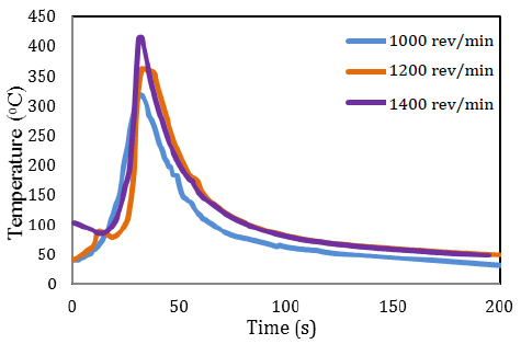
Figures 8-10 show the temperature histories of the thermocouples with respect to welding time in various locations with respect to time during the FSW process. As seen from the figures, temperature values increase with increasing the rotational speed of the pin. In order to ensure a better evaluation of the measurement results, the temperature values for the node defined as N4 are selected and Figure 11 is drawn for the same time scale. The maximum values of the temperature histories for the rotational speeds of 1400 rev/min, 1200 rev/min and 1000 rev/min are 414.9oC, 360.8oC and 314.9oC, respectively.
Temperature measurements for the cases of transverse speed of 120 mm/min and rotational speed of 1000 rev/min.
Temperature measurements for the cases of transverse speed of 120 mm/min and rotational speed of 1200 rev/min.
Temperature measurements for the cases of transverse speed of 120 mm/min and rotational speed of 400 rev/min.
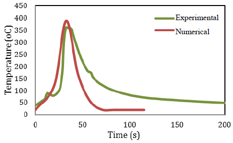
Figure 12 presents the variation of temperature in location N4 obtained by the transient finite element analyses. As seen from the figure, temperature increases as the rotational speed increases as observing from the measurements. The maximum temperature values are 414.95oC, 389.02oC and 327.02oC for the rotational speeds of 1400 rev/min, 1200 rev/min and 1000 rev/min, respectively. Similar tendency as in the experiments is observed. Figures 13-15 show the comparison of the numerical and experimental temperature values determined for N4. Despite both the numerical and experimental maximum temperature values are close to each other, some discrepancies are seen in the temperature values during the cooling. The reason is that the finite element analyses are performed in the ideal and steady environment conditions where as the heat transfer cannot be controlled in the experiments.
Numerical and experimental temperature variation for the case of rotational speed 1000 rev/min.
Numerical and experimental temperature variation for the case of rotational speed 1200 rev/min.
Numerical and experimental temperature variation for the case of rotational speed 1400 rev/min.
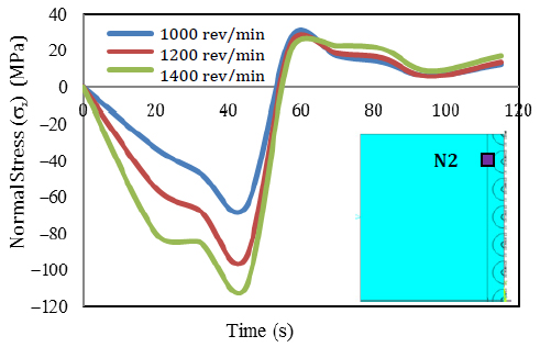
Normal stress (σx) histories at location N2 can be seen in Figure 16. It is revealed that normal stress, σx changes from compressive values to tensile values during the welding. As seen from the figure, when the rotational speed increases, the stress also increases similar to the temperature values.
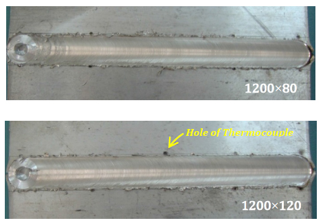
The welding trials of the AZ31 Mg alloy plates were conducted using a CNC milling machine. Effect of the rotational and transverse speeds indicated in Table 1 on the weld performance was investigated. As a result of the first stage of experiments performed, no weld defect took place in the joint produced with the weld parameter of 1200 rev/min. Figure 17 shows some welded plates joined at the rotational speed of 1200 rev/min. At the second stage of the experiments, the welding of the plates was performed using weld parameters of 80, 100, 120 and 140 mm/min and 1200 rev/min.
3.1 Tensile Properties
Figure 18 shows the stress-strain curves of the tensile-tests of the specimen extracted from welded AZ31 Mg alloy plate. Tensile tests were conducted using a universal tensile machine with a load capacity of 100 kN. All tensile tests were carried out based on ASTM E8/E8M-11 standard at room temperature using a rate of 1 mm/min. As seen from the figure, all tensile specimens exhibit brittleness.
Stress-strain curves of AZ31 for 1200 rev/min 80 mm/min, 100 mm/min, 120 mm/min, 140 mm/min.
Table 5 gives the summary of the results obtained from all the tensile tests. All tensile test specimens failed in the heat affected zone as seen from Figure 19. The joints exhibit about 55% joint efficiency as seen from the table except specimen 1200/140. The elongation of the joints was about 9-10% except specimen 1200/140.
3.2 Microstructural Aspects
When the welded joints were investigated macrographs by a microscopy, some weld defects were observed (Figure 20). As it is well known, welding of magnesium alloys is hard to other structural materials so it was come up some typical problem such as porosity because of hydrogen dissolves completely in the heating process and is separated out while temperature decreases (Liu, 2010Liu, L., (2010). Welding and joining of magnesium alloys. Woodhead Publishing.). The generated heat and plastic deformation rate are very important during the welding. It was revealed that the dimension of the weld defect decreases as the transverse speed decreases. These weld defects affected the welding performance inherently.
Metallography specimens were extracted from joints for microstructural examinations. It is explained that metallurgical changes of friction stir welded magnesium alloys and effect of welding parameters to the evolution of microstructure. For this purpose, after grinding and polishing, the specimens were etched using 20 ml acetic acid, 20 ml distilled water, 3 gr picric acid and 50 ml ethanol for 3-5 s.
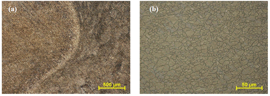
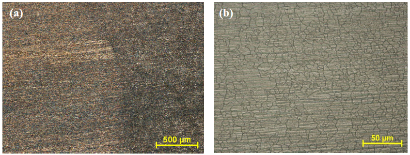
The micrographs of base metal and welded joints are given in Figure 21 and Figures 22-25, respectively. When the welded joints were investigated by a microscopy, grain size structure of base metal are changed into the grain refinement in the stirring zone duetodynamicrecrystallization. The joints performed with a rotational speed of 1200 rev/min, transverse speed of 80 mm/min, contain finer grains in the stirring zone compared to other joints. But stirring zone in other joints shows similar grain structure, the size of grain structure changed slight. One of the reasons of emerged this formation was generated heat during the welding. Because, transverse speed effect the generated heat end plastic deformation. If the transverse speed is increase the grain structure is change slight. Especially, the joints performed with transverse speed of 140 mm/min was threw this situation into sharp relief.
Microstructural view of the welded specimen produced at 1200 rev/min - 80 mm/min a) transition zone b) stir zone.
Microstructural view of the welded specimen produced at 1200 rev/min - 100 mm/min a) transition zone b) stir zone.
Microstructural view of the welded specimen produced at 1200 rev/min - 120 mm/min a) transition zone b) stir zone.
Microstructural view of the welded specimen produced at 1200 rev/min - 140 mm/min a) transition zone b) stir zone.
3.3 Hardness
Vickers micro hardness measurements were carried out on the specimens along the centerline across the joint using a load of 100 g for loading time of 10 s. Figure 26 shows the hardness profiles obtained from the welded joints. As seen from the figure, hardness increases in the weld regions of all the joints. The increase in the hardness is very similar in all the joints produced at different transverse speeds. On the other hand, even if just a bit a hardness loss occurred in the stir and heat affected zones. The lowest hardness value in the stir zone was displayed on the joints produced at the transverse speed of 100 mm/min. When the transverse speed of 80 mm/min was used, the hardness of welding zone is the most close to that of the base metal. The hardness of the heat affected zone is close to that of base metal for all the joints. Vickers hardness value of base metal is about 70 HV.
4 CONCLUSIONS
The following conclusions can be drawn from the present study:
-
FSW of the AZ31 Mg-Alloy plates can be carried out at the rotational speed of 1200 rev/min and the transverse speeds of 80, 100, 120 and 140 mm/min.
-
Rotational speed of the pin affects more the temperature distribution in the weld region than the transverse speed of the pin.
-
As the rotational speed increases, temperature near the weld region as well as normal and transverse stresses increases.
-
There is good agreement in the temperature results obtained by experiments and numerical analyses. Discrepancies in the numerical and experimental temperature values during the cooling of the metal occur since there is not enough information about the convection and ambient temperature may change during the trials.
-
It is revealed that mechanical properties of the welded joints improve at the low transverse speeds.
-
Although tensile strength is low, the specimen produced at the transverse speed of 140 mm/min display the most suitable distribution in terms of the hardness.
-
It is seen that the welding performance increases as both low transverse speed and high rotational speed increase.
REFERENCES
- Albakri A.N., Mansoor B., Nassar H., Khraisheh M.K., (2013). Thermo-mechanical and metallurgical aspects in friction stir processing of AZ31 Mg alloy- A Numerical and experimental investigation. J Mater Process Tech, 213: 279-290.
- Cam G., (2011). Friction stir welded structural materials: beyond Al-alloys. Int Mat Rev, 56: 1, 1-48.
- Cao X., Jahazi M., (2009). Effect of welding speed on the quality of friction stir welded butt joints of a magnesium alloy. Mater Design, 30: 2033-2042, 2009.
- Chai F., Zhang D., Li Y., (2014). Effect of thermal history on microstructures and mechanical properties of AZ31 magnesium alloy prepared by friction stir processing. Materials, 7: 1573-1589.
- Chang, C.I., Lee C.J., Huang J.C., (2004). Relationship between grain size and Zener-Holloman parameter during friction stir processing in AZ31 Mg alloys. Scripta Mater, 51: 509-514, 2004.
- Chowdhury S.H., Chen D.L., Bhole S.D., Cao X., Wanjara P., (2012). Friction Stir Welded AZ31 Magnesium Alloy: Microstructure, Texture, and Tensile Properties.Metall Mater Trans A, 44A: 323-336.
- Commin L., Dumont M., Masse J.-E., Barrallier L., (2009). Friction stir welding of AZ31 magnesium alloy rolled sheets: Influence of processing parameters. Acta Mater, 57, 326-334.
- Darras B.M., (2012). A Model to predict the resulting grain size of friction-stir-processed AZ31 magnesium alloy. J Mater Eng Perform, 21(7): 1243-1248.
- Darras B.M., Khraisheh, M.K., Abu-Farha F.K., Omar M.A., (2007). Friction stir processing of commercial AZ31 magnesium alloy. J Mater Process Tech. 191: 77-81.
- Fu R.D., Ji H.S., Li Y.J., Liu L., (2012). Effect of weld conditions on microstructures and mechanical properties of friction stir welded joints on AZ31B magnesium alloys. SciTechWeldJoi, 17:174-179.
- Gharacheh M.A., Kokabi A.H., Daneshi G.H., Shalchi B., Sarrafi R., (2006). The influence of the ratio of rotational speed/traverse speed (ω/v) on mechanical properties of AZ31 friction stir welds. Int J Mach Tool Manu, 46: 1983-1987.
- Gök, K., Aydın, M., (2013). Investigations of frictions tir welding process using finite element method. Int J AdvManufTech, 68, 775-780.
- Jabbari M., “Effect of the Preheating Temperature on Process Time in Friction Stir Welding of Al 6061-T6”, Journal of Engineering, Vol. 2013, pp. 1-5, 2013.
- Liu, L., (2010). Welding and joining of magnesium alloys. Woodhead Publishing.
- Mishra R.S., Mahoney M.W., “Friction Stir Welding and Processing”, ASM International, 2007.
- Mishra R.S.,Ma Z.Y., (2005). Frictionstirweldingandprocessing. Mater SciEng R, 50: 1-78.
- Padmanaban G., Balasubramanian V., Sarin Sundar J.K., (2010). Influences of Welding Processes on Microstructure, Hardness, and Tensile Properties of AZ31B Magnesium Alloy. J Mater Eng Perform, 19: 155-165.
- Schmidt, H., Hattel, J., Wert, J., (2004). An analytical model for the heat generation in friction stir welding. Model Simul Mater Sc, 12, 143-157.
- Serindag, H.T.,GorenKiral, B., Kadayifci, Z.A., (2014). Finite element analysis of frictionstirweldedaluminumalloy AA6061-T6 joints. Materialprufung 56(11-12): 937-944.
- Soundararajan, V., Zekovic, S., Kovacevic, R., (2005). Thermo-mechanical model with adaptive boundary conditions for friction stir welding of Al 6061. Int J Mach Tool Manu. 45(14): 1577-1587.
- Suhuddin U.F.H.R., Mironov S., Sato Y.S., Kokawa H., Lee C.W., (2009). Grain structure evolution during friction-stir welding of AZ31 magnesium alloy. Acta Mater, 57: 5406-5418.
- Vepakomma, K.H., (2006). Three dimensional thermal modeling of friction stir processing. The Florida State University College of Engineering, MSc Thesis.
- Wen W., Kuaishe W., Qiang G., Nan W., (2012). Effect of friction stir processing on microstructure and mechanical properties of cast AZ31 magnesium alloy. Rare Metal Mat Eng, 41(9): 1522-1526.
- Xunhong, W., Kuaishe, W., (2006). Microstructure and properties of friction stir butt-welded AZ31 magnesium alloy.Mater SciEng A, 431: 114-117.
- Yang H., Huang L., Zhan M., (2011). Hot forming characteristics of magnesium alloy AZ31 and three-dimensional FE modelling and simulation of the hot splitting spinning process. Magnesium Alloys-Design, Processing and Properties, 367-388.
- Yang J., Wang D., Xiao B.L., Ni D.R., Ma Z.Y., (2013). Effects of rotationrates on microstructure, mechanicalproperties, andfracturebehavior of frictionstir-welded (FSW) AZ31 magnesiumalloy. Metall Mater Trans A: 517-530.
Publication Dates
-
Publication in this collection
Jan 2017
History
-
Received
13 June 2016 -
Reviewed
02 Sept 2016 -
Accepted
14 Nov 2016