
Abstract
Textile Reinforced Mortar (TRM), also known as Fabric Reinforced Mortar or Fabric Reinforced Cementitious Matrix, composites are an emerging technology for the external repair and strengthening of existing structures. For most applications, the effectiveness of the TRM reinforcement relies on its bond performance. This recommendation identifies the best practice to characterize the bond behaviour of TRM. A shear bond test method is proposed to determine the peak axial stress (associated with the maximum load that can be transferred from the structural member to the externally bonded TRM reinforcement), the stress–slip relationship and the failure mode that controls the TRM-to-substrate load transfer capacity. Guidelines on specimen manufacturing, experimental setup, test execution, and determination of test results are provided.
1 Introduction
Textile Reinforced Mortar (TRM) composites consist of a textile bonded by means of an inorganic matrix to the external surface of existing structures for repair or strengthening purposes. Textiles are made of either continuous fibre bundles of glass, carbon, basalt, aramid, or polyparaphenylene benzobisoxazole (PBO) and arranged in the form of open meshes (generally bidirectional grids), or steel cords or ropes (which are unidirectional). Textiles with natural fibres (e.g., flax, hemp) are also under development for TRM applications. To improve durability and textile-to-matrix bond, fibre bundles can be coated or pre-impregnated, while steel cords are galvanized (zinc coated) or made of stainless steel. Cement, lime, cement/lime, alkali-activated alumino-silicate, or geopolymer mortars (possibly including short fibres and/or polymeric additives) are used as matrices. As an alternative to TRM, the acronyms Fabric Reinforced Mortar (FRM) and Fabric Reinforced Cementitious Matrix (FRCM) are also used in the scientific literature, whereas Steel Reinforced Grout (SRG) is generally adopted for systems that employ steel textiles.
TRMs offer the same advantages of fibre reinforced polymers (FRPs), such as high strength-to-weight ratio, relatively fast and easy installation, and versatility (possibility of being applied in many different configurations). Moreover, the inorganic matrices employed in TRMs instead of the organic (e.g., epoxy) matrices of FRPs result in better behaviour of the composite at elevated temperatures and ensure easier and faster installation on uneven or wet substrates, with no risks for the workers due to the absence of toxic volatile compounds. Finally, the use of lime-based mortars, as well as of some alkali-activated alumino-silicate or geopolymer mortars, ensures the vapour permeability and physical/chemical compatibility with historic masonry substrates required for applications related to architectural heritage [1, 2] (Online Resource 1).
In a large number of structural applications, including the strengthening of masonry walls, the strengthening of arches and vaults, and the strengthening of lintels and eaves, the effectiveness of the strengthening work relies on the TRM-to-substrate bond behaviour, which, therefore, needs to be characterized for the design of the reinforcement and for the assessment of the retrofitted structural member. Experimental investigations (e.g., [3,4,5,6,7]) have shown that, differently from FRPs, the TRM-to-substrate bond failure may take place not only within the substrate, but also within the thickness of the composite. The TRM-to-substrate load transfer mechanism depends upon the bond between matrix and substrate, the fabric-to-matrix adhesion/interlocking and the fibre-to-fibre bond. Accordingly, the load transfer capacity may be affected by the textile architecture, the coating or pre-impregnation of the fibres, the mechanical characteristics and thickness of the matrix, the properties of the substrate (strength and Young’s modulus, roughness, moisture content), as well as by the quality of the application and the curing conditions.
This recommendation identifies the best practice to characterize the bond behaviour of Textile Reinforced Mortars, based on the knowledge gained so far, including the recent developments achieved within the activities of the Rilem TC 250-CSM: Composites for the Sustainable Strengthening of Masonry. A shear bond test method to characterize the TRM-to-substrate bond behaviour, related to the termination (end) of the TRM strip, is proposed. The test provides (i) the peak axial stress, referred to the cross-sectional area of the load-aligned (longitudinal) fibres of the textile, which is associated to the maximum load that can be transferred from the structural member to the externally bonded TRM reinforcement, (ii) the axial stress–slip relationship, the slip being the relative displacement between the substrate and the textile at the loaded end of the bonded area, and (iii) the failure mode that controls the TRM-to-substrate load transfer capacity.
Test results may be used for the mechanical characterization of externally bonded TRM reinforcements, possibly within certification protocols.
2 Scope
The aim of this recommendation is to describe a standardized shear bond test method to characterize the TRM-to-substrate bond behaviour. The axial stress–slip relationship of a TRM strip applied onto a substrate prism and subjected to a load parallel to the composite-to-substrate interface is obtained. Possible effects of additional in-plane or out-of-plane stress components (due to misalignments, other external loads, curved substrates, etc.) are not considered. The recommendation is only valid for quasi-static monotonic testing. The peak axial stress attained in the shear bond test, the axial stress–slip relationship, and the failure mode, are determined from test data. Bond tests are meant to be carried out on a TRM system with a given layout/grid spacing and surface mass density of the textile, installed in one or two plies with a given mortar matrix. The results obtained from the test should be considered valid only for the TRM system and substrate under investigation and cannot be directly extended or extrapolated to different composites or substrate materials.
3 Referenced standards
The following standards are applicable within the scope of this Recommendation:
ISO 9513:1999: Metallic materials—Calibration of extensometers used in uniaxial testing.
ISO 7500-1:2004: Metallic materials—Verification of static uniaxial testing machines—Part 1: Tension/compression testing machines—Verification and calibration of the force-measuring system.
4 Definitions
- Bonded area:
-
Area of TRM strip in contact with the substrate (B × L, as in width × length). The thickness of the TRM strip is denoted by T.
- Effective bond length:
-
Minimum length of the bonded area in the longitudinal direction beyond which a quasi-stabilization of the peak axial stress is observed, i.e., an increase in bond length is not associated to a significant increase in peak axial stress.
- Effective textile width (wf):
-
Product of number of load-aligned yarns per textile layer and the mid-yarn (or mid-cord/mid-rope) spacing (normal to the load application direction).
- Exploitation ratio (η):
-
Ratio between the peak axial stress attained in the bond test (fb) and the tensile strength (ft) of the composite: η = fb/ft.
- Loaded end:
-
End of the bonded area closer to the load application fixture.
- Mean ultimate shear stress (τbm):
-
Maximum value of the mean shear stress at the composite-to-substrate interface, calculated the peak load divided by the bonded area: τbm = Fb/(B × L).
- Peak axial stress (fb):
-
Maximum axial stress in the textile attained in the bond test, calculated as the peak load divided by the cross-sectional area of all load-aligned (longitudinal) fibres: fb = Fb/Af.
- Peak load (Fb):
-
Maximum load attained in the test.
- Peak slip (sb):
-
Slip corresponding to the peak axial stress.
- Slip (s):
-
Relative displacement between the textile and the substrate at the loaded end of the bonded area.
- Tensile strength (ft):
-
Tensile strength of the TRM composite, along the same direction as the one used in the bond test, derived from uniaxial monotonic tensile tests (not in the scope of this recommendation, see [8]); the tensile strength refers to the area of the fibres.
- Textile area (Af):
-
Net cross-sectional area of the textile, calculated as the product of the effective textile width and its equivalent thickness normal to the direction of load: Af = wf × tf.
- Equivalent textile thickness (tf):
-
Equivalent thickness of the fibres parallel to the load application direction, assuming fibres to be smeared along the effective textile width, wf. tf is either provided by the supplier or computed as the surface mass density of the textile (i.e., of the fibres parallel to the load application direction) divided by the bulk density of the material of the dry fibres (weight of coating or impregnation material not included).
5 Test specimen
5.1 Geometry
-
1.
Shear bond tests are carried out on prismatic straight substrates, such as concrete block, brick masonry, tuff masonry, stone masonry. If the TRM employs a commercial system (i.e., textile plus mortar provided by the same manufacturer), then the substrates are proposed by the supplier as perspective field applications of the system (Online Resource 2).
-
2.
The TRM strengthening system is installed on one side of the substrate prism with one of the directions of the fibres parallel to the longitudinal axis of the specimen and symmetric to the centreline of the specimen width-wise (Fig. 1). The portion of the substrate to which the system is applied is termed bonded area. A portion of bare textile is left unbonded on one side of the bonded area.
Fig. 1 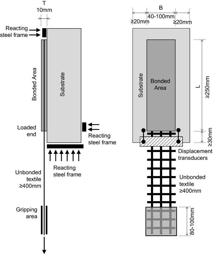
Geometry of the specimen
-
3.
For most cases (porous substrates), TRM application is carried out on a saturated substrate. If the TRM comprises a commercial system, the instructions provided by the supplier in the product technical data sheet must be observed in the installation. In particular, any required preliminary actions (wetting with water, brushing, etc.) and specific surface preparation procedures (bush hammering, consolidation with potassium silicate or others, application of primer to promote adhesion, etc.) should be followed and stated in the test report.
-
4.
The thickness of the TRM reinforcement (T) is commonly equal to 10 mm. If the TRM comprises a commercial system, the thickness shall be the one required in the installation manual. Thickness larger than 30 mm should be avoided. The thickness shall be kept constant over the entire bonded area. The textile shall be placed in the middle of the thickness.
-
5.
The width of the bonded area (B) should be at least 40 mm. It should be an integer multiple of the grid spacing and should include at least three yarns/cords.
-
6.
The length of the bonded area (L) should be longer than the effective bond length, to ensure that the TRM-to-substrate load transfer capacity is fully exploited. Experimental outcomes [9] have shown that shear bond tests can be performed with a bond length of 300 mm for most of the TRM systems currently available. Bond lengths shorter than 250 mm may be insufficient and are therefore not recommended. On the other hand, significantly longer bond lengths could be used, but it should be considered that, in case of failure by textile slippage, this may lead to higher peak loads due to the textile-to-mortar friction (interlocking) that is activated where the textile has debonded from the matrix.
-
7.
In order to reduce edge effects, the distance between the lateral edge of the bonded area and that of the substrate should be at least 20 mm. Moreover, the distance between the start of the bonded region at the loaded end (i.e., on the end where load is applied) and the nearest edge of the substrate should be at least 30 mm.
-
8.
During manufacturing, particular attention should be paid in the regularity of the reinforcement and in the planarity and parallel arrangement of fibre bundles/cords. To this aim, a pre-load (one that produces an axial stress to the load-aligned fibres of no more than 10 N/mm2) can be applied to the textile during mortar curing.
-
9.
If the TRM systems comprises two plies, careful attention should be paid to their parallel arrangement during installation.
-
10.
In order to reduce possible normal stresses at the reinforcement-to-substrate interface, which may be caused by slight misalignments, the length of the unbonded textile should be at least 400 mm, including the length of the portion of the textile gripped within the clamping wedges.

5.2 Curing and storage
Curing should last at least 28 days or, in case of commercial systems, as specified in the product technical data sheet. In the curing phase, adequate relative humidity conditions should be ensured to minimize the development of differential shrinkage, which could cause cracking and/or premature detachment of the TRM strip from the substrate. To this aim, curing can be made in a humidity-controlled chamber; as an alternative, the bonded area can be covered with wet clothes and/or with plastic film, and kept in plastic bags. Prior to testing, the specimen should be stored in standard laboratory conditions (approximately 20–25 °C and 50–60% R.H.) for at least 7 days. Should special curing regimes be followed, these will be described in the test report.
6 Test condition and equipment
6.1 Environment
The tests are carried out in laboratory environment, as referred to in Sect. 5.2.
6.2 Testing machine
Tests are carried out under displacement control, with a universal testing machine, provided with suitable capacity and able to perform tests at a rate of 0.2 mm/min or less. The accuracy of the extensometers should be in agreement with ISO 9513 and the force measuring system in agreement with ISO 7500-1.
6.3 Test setup
-
1.
Tests are performed with a push–pull single-lap shear setup. Amongst the numerous setups proposed in the scientific literature (including double-lap setups with single or double substrate prism, and bending setup), this is the simplest one in terms of specimen manufacturing and handling, and requires the monitoring of only one bonded area. Moreover, the load applied to the reinforcement is directly provided by the load cell. On the other hand, it requires particular attention to the relative alignment of the steel frame and the specimen, both during preparation and during test execution [9], as well as in the alignment of the unbonded textile and of the displacement transducers (Fig. 1).
-
2.
The specimen is placed in a steel frame (made of plates to form an angle of 90°), which is stiff enough to avoid rotations and distortions. The frame should be designed to avoid the rotation of the specimen (Online Resource 3). Reacting plates can be used to this aim [9]. The frame should preferably be fixed to the fixed part of the testing machine, while the unbonded textile should be clamped in wedges on the other part, and pulled. A careful positioning of the specimen is necessary to ensure load alignment with the pulled textile strip and minimize the effect of eccentricities, namely the generation of spurious normal stresses at the substrate-to-matrix interface.
-
3.
The loaded end of the textile should be clamped in a way that guarantees a homogeneous distribution of the clamping stresses and the avoidance of slippage phenomena within the clamps. For this purpose, tabs made of a variety of materials (e.g., aluminium, steel, or FRP) can be used. Tabs should be of a width equal to the effective width of the textile and a length of 80–100 mm.
-
4.
The unbonded textile can be impregnated (e.g., with resin or mortar) to improve the distribution of the load width-wise. Nevertheless, test results suggest that the peak axial stress is not significantly affected by the impregnation of the unbonded textile [3,4,5,6,7, 9].
6.4 Measuring devices
-
1.
The load (F) is recorded by a load cell with suitable capacity, resolution and accuracy (to be certified).
-
2.
In order to calculate the slip (s), displacements are measured by means of two displacement transducers with suitable resolution and accuracy (to be certified), that are applied to the specimen near the loaded end of the TRM reinforcement, one per side of the TRM.
-
3.
Due to possible occurrence of brittle phenomena, the sampling frequency should be at least 5 Hz.
7 Test procedure
7.1 Preparation and installation of specimens
-
1.
Prior to testing, the TRM strip is measured in at least three different sections with instruments having accuracy within 1% of the mortar thickness. Measurements are reported and should not differ from the nominal ones by more than ± 10% for both the width (B) and the thickness (T).
-
2.
Specimen is placed in the setup taking care of the alignment between the textile and the applied load.
-
3.
Displacement measuring instruments are installed.
7.2 Test execution
-
1.
Tests are carried out under displacement control. The control parameter should be the displacement measured by the displacement transducer integrated in the testing machine or by another transducer applied to the specimen to record the slip.
-
2.
A pre-load equal to 5% of the expected peak load can be applied before the start of the test.
-
3.
The displacement is increased monotonically up to failure at a machine stroke rate comprised between 0.15 and 0.30 mm/min.
-
4.
At least five samples, nominally identical and manufactured at the same time, should be tested.
8 Evaluation of test results
8.1 Stress–slip relationship
-
1.
The main test result is the axial stress–slip relationship, presented in the form of x–y-diagrams with slip on the x-axis and stress on the y-axis. The TRM-to-substrate response generally exhibits an initial linear phase, followed by a non-linear phase up to the attainment of a peak stress value, and a post-peak phase in which the increase of slip is associated to a decrease of the stress (a schematic plot is shown in Fig. 2).
Fig. 2 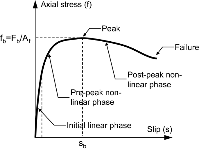
Schematic axial stress–slip relationship
-
2.
The axial stress (f) is obtained as the load divided by the cross section area of the load-aligned fibres of the textile. The peak axial stress (fb) is the maximum stress value attained in the shear bond test, referred to the cross-sectional area of load-aligned (longitudinal) fibres.
-
3.
The slip (s) shall be calculated as the average of the displacements measured by the two displacement transducers. The elastic elongation of the unbonded textile comprised between the loaded end of the bonded area and the section of the textile that is monitored by the displacement transducers has to be removed from the recorded displacement. The slip can be due to slippage of the textile to the matrix-to-substrate relative strain and displacement, or to a combination of these two. Using the instrumentation described herein, the sum of the two contributions is measured. Additional displacement transducers and/or contactless measurement techniques (e.g., the Digital Image Correlation) could be used to measure each contribution individually. The peak slip (sb) is the slip value corresponding to the peak axial stress fb.

8.2 Failure mode
The failure mode is observed and provided in the test report. Failure modes are classified as follows: (A) debonding with cohesive failure of the substrate; (B) debonding at the matrix-to-substrate; (C) debonding at the textile-to-matrix interface; (D) textile slippage within the matrix, with or without cracking of the outer mortar layer; (E1/E2) tensile rupture of the textile (meaning partial or complete rupture of one or more fibre yarns) out of the bonded area or within the matrix (with telescopic failure of the bundle), respectively (Fig. 3). Mixed failure mode may take place and this should be specified in the test report.

Failure modes
Failure mode A usually occurs when a strong matrix (e.g., cement or geopolymer-based, with organic additives, etc.) is bonded to a weak substrate (e.g., tuff unit). Failure mode B usually takes place on relatively smooth surfaces and/or may be associated with limited substrate preparation or unfavourable curing conditions. Failure mode C is governed by the amount the mortar through the voids between fibre bundles or cords, and is often exhibited by TRM systems comprising textiles with small grid/cord spacing. Failure mode D usually takes place when dry fibre bundles (not provided with coating or pre-impregnation) or smooth ropes, characterized by a relatively weak bond/interlocking with the matrix, are used. Finally, TRM systems comprising relatively weak textiles with small equivalent thickness may exhibit failure mode E1 (generally when fibre bundles are provided with pre-impregnation or coating) or failure mode E2 (when dry textiles are used).
9 Test report
The test report should include at least the following information:
-
1.
General information
-
i.
Origin and description of the test specimens: constituents and supplier(s) of TRM system, type, geometry and mechanical properties of the substrate, mechanical properties of textile and mortar matrix, as stated in the technical data sheet of the supplier or determined by mechanical characterization tests on constituent materials (not in the scope of this recommendation).
-
ii.
Specimen geometry: dimensions of the bonded area and distance from the edges of the substrate prism, number of textile layers, length of the unbonded textile, cross-sectional area of the textile.
-
iii.
Preliminary actions and specific surface preparation procedures observed before and during TRM installation. Pre-tensioning applied during mortar curing.
-
iv.
Curing and storage conditions: temperature in °C and relative humidity in %.
-
v.
Age at testing of the specimens.
-
vi.
Detailing of the gripping method for the unbonded textile.
-
vii.
Laboratory identity (institution, location) and characteristics of the instrumentation: testing machine (type and load capacity), load cell (accuracy and resolution), displacement transducers/extensometer (gauge length, accuracy and resolution). Date of the test.
-
viii.
Control parameter and displacement rate. Pre-tensioning applied.
-
i.
-
2.
Test results
-
i.
Axial stress–slip response curve (stresses being referred to the cross-section of the textile Af).
-
ii.
Peak load and axial peak stress, and corresponding mean ultimate shear stress and slip (Fb, fb, τbm, sb).
-
i.
Exploitation ratio of tensile strength, in percent, defined as η = fb/ft, ft being the tensile strength of the TRM system derived from direct tensile tests. Direct tensile tests can be carried out following the recommendation of RILEM TC 232-TDT [8] or other adequate experimental procedures [9].
-
ii.
Failure mode, according to the classification provided in Fig. 2.
-
i.
-
3.
Results should be provided for each specimen. Mean, standard deviation and coefficient of variation of each parameter should also be calculated for the set of specimens.
References
Papanicolaou CG, Triantafillou TC, Karlos K, Papathanasiou M (2007) Textile Reinforced Mortar (TRM) versus FRP as strengthening material of URM walls: in-plane cyclic loading. Mater Struct 40(10):1081–1097. https://doi.org/10.1617/s11527-006-9207-8
de Felice G, De Santis S, Garmendia L, Ghiassi B, Larrinaga P, Lourenço PB, Oliveira DV, Paolacci F, Papanicolaou CG (2014) Mortar-based systems for externally bonded strengthening of masonry. Mater Struct 47(12):2021–2037. https://doi.org/10.1617/s11527-014-0360-1
Caggegi C, Carozzi FG, De Santis S, Fabbrocino F, Focacci F, Hojdys L, Lanoye E, Zuccarino L (2017) Experimental analysis on tensile and bond properties of PBO and Aramid Fabric Reinforced Cementitious Matrix for strengthening masonry structures. Compos Part B Eng 127:175–195. https://doi.org/10.1016/j.compositesb.2017.05.048
Carozzi FG, Bellini A, D’Antino T, de Felice G, Focacci F, Hojdys L, Laghi L, Lanoye E, Micelli F, Panizza M, Poggi C (2017) Experimental investigation of tensile and bond properties of Carbon-FRCM composites for strengthening masonry elements. Compos Part B Eng 128:100–119. https://doi.org/10.1016/j.compositesb.2017.06.018
De Santis S, Ceroni F, de Felice G, Fagone M, Ghiassi B, Kwiecień A, Lignola GP, Morganti M, Santandrea M, Valluzzi MR, Viskovic A (2017) Round Robin Test on tensile and bond behaviour of Steel Reinforced Grout systems. Compos Part B Eng 127:100–120. https://doi.org/10.1016/j.compositesb.2017.03.052
Leone M, Aiello MA, Balsamo A, Carozzi FG, Ceroni F, Corradi M, Gams M, Garbin E, Gattesco N, Krajewski P, Mazzoti C, Oliveira DV, Papanicolaou CG, Ranocchiai G, Roscini F, Saenger D (2017) Glass Fabric Reinforced Cementitious Matrix: tensile properties and bond performance on masonry substrate. Compos Part B Eng 127:196–214. https://doi.org/10.1016/j.compositesb.2017.06.028
Lignola GP, Caggegi C, Ceroni F, De Santis S, Krajewski P, Lourenço PB, Morganti M, Papanicolaou C, Pellegrino C, Prota A, Zuccarino L (2017) Performance assessment of basalt FRCM for retrofit applications on masonry. Compos Part B Eng 128:1–18. https://doi.org/10.1016/j.compositesb.2017.05.003
RILEM Technical Committee 232-TDT (Chair: Wolfgang Brameshuber) (2016) Recommendation of RILEM TC 232-TDT: test methods and design of textile reinforced concrete. Mater Struct 49(12):4923–4927. https://doi.org/10.1617/s11527-016-0839-z
De Santis S, Carozzi FG, de Felice G, Poggi C (2017) Test methods for Textile Reinforced Mortar systems. Compos Part B Eng 127:121–132. https://doi.org/10.1016/j.compositesb.2017.03.016
Author information
Authors and Affiliations
Corresponding author
Ethics declarations
Conflict of interest
The authors declare that they have no conflict of interest.
Additional information
TC Membership:
Chairman: G. de Felice, Italy, Roma Tre University, Rome.
Secretary: D.V. Oliveira, Portugal, University of Minho, Guimarães.
Members: M.A. Aiello, Italy; M.C. Bignozzi, Italy; M. Briffaut, France; C. Caggegi, France; G. Cardani Italy; P. Casadei, Italy; F. Ceroni, Italy; M. Corradi, Italy; T. D’Antino, Italy; S. De Santis, Italy; L. De Lorenzis, Italy; M. Gams, Slovenia; E. Garbin, Italy; L. Garmendia, Spain; N. Gattesco, Italy; B. Ghiassi, Netherlands; Ł. Hojdys, Poland; M. Imbimbo, Italy; E. Kamseu, Italy; P. Krajewski, Poland; A. Kwiecień, Poland; M. Leone, Italy; G.P. Lignola, Italy; P.B. Lourenço, Portugal; G. Manfredi, Italy; C. Mazzotti, Italy; V. Mechtcherine, Germany; F. Micelli, Italy; C. Modena, Italy; M. Motavalli, Switzerland; C. Papanicolaou, Greece; C. Poggi, Italy; A. Prota, Italy; E. Sacco, Italy; A. Saisi, Italy; T. Stryszewska, Poland; C. Tedeschi, Italy; T. Triantafillou, Greece; M.R. Valluzzi, Italy; E. Verstrynge, Belgium; A. Viskovic, Italy; B. Zając, Poland.
Other contributors: C. Carloni Italy; A. Nanni, USA; M. Panizza, Italy.
Acknowledgements: This recommendation was prepared by a working group within RILEM TC-250 CSM coming from thirteen laboratories. The draft was approved by the all TC members (see the list below). The contributions by the other contributors (cited below) to the work of the TC are gratefully acknowledged.
Electronic supplementary material
Below is the link to the electronic supplementary material.
Rights and permissions
About this article

Cite this article
de Felice, G., Aiello, M.A., Caggegi, C. et al. Recommendation of RILEM Technical Committee 250-CSM: Test method for Textile Reinforced Mortar to substrate bond characterization. Mater Struct 51, 95 (2018). https://doi.org/10.1617/s11527-018-1216-x
Received:
Accepted:
Published:
DOI: https://doi.org/10.1617/s11527-018-1216-x