


Introduction
There is a wide variety of intriguing connections between ice structure at the molecular level and the macroscopic characteristics of ice. for example, differential rates of ice growth on the basal vs prism planes determine the crystal morphology in snow (Reference LibbrechtLibbrecht, 2005). snow crystal morphology can then impact a range of physical properties. similar connections exist between the molecular and the macroscopic scales for sea ice. despite the enormous dimensions of sea ice, its formation is a molecular process, and the importance of a microscopic description has been recognized (Reference Eicken, Thomas and DieckmannEicken, 2003). the details of salt rejection upon freezing are important not only to sea-ice physics, but to sea-ice surface structure. the exclusion of salt from freezing sea ice results in the creation of brine drainage channels, which influence the macroscopic properties such as the sea-ice tensile strength, and thus its deformation and cracking as a result of large-scale sea-ice motion (Reference Shibkov, Golovin, Zheltov, Korolev and LeonovShapiro and weeks, 1993). salt exclusion from freezing ultimately leads to frost flower formation (Reference PruppacherPerovich and richter-menge, 1994), which is implicated in a number of photochemical processes above sea-ice surfaces. frost flowers on refrozen leads have been hypothesized to represent an important mechanism for halogen release into the atmosphere (Reference Rankin, Wolff and MulvaneyRankin and others, 2000), which results in very active surface chemistry in the arctic, hypothesized to result in transformations that lead to deposition of atmospheric mercury into the ocean (Reference S.E.Lindberg and others, 2002). indeed, there is an intriguing connection between sea-ice surface structure and sea salt found in ice cores, as discussed by Reference Shapiro, Weeks, Dempsey, Baezant, Rajapakse and SunderRankin and others (2004). it is thus clear that the disposition of the ionic components of sea water upon freezing has substantial implications for seawater salinity, sea-ice physics, and overlying atmospheric chemistry and composition.
Here we present a molecular dynamics (md) simulation study of the growth of hexagonal ice from an existing ice–water and ice–brine interface at supercooled conditions. to our knowledge, this is the first set of complete simulations that predict hexagonal ice growth from brine solution. for the growth from pure water, this paper is a continuation of our previous publication on ice growth with explicit ice/water/vapor interfaces (Reference Carignano, Shepson and SzleiferCarignano and others, 2005). for the case of growth from salt solutions, we obtain a slower growth rate than in the pure water system, an intermediate metastable state and a clustering of the ions upon freezing. this work has some similarities with the work of Reference Vrbka and JungwirthVrbka and jungwirth (2005), in which they studied brine rejection from cubic ice. also, thermodynamics and structural properties of ions at a stable ice/water interface, i.e. with no appreciable freezing or melting, were recently studied by the haymet group (Reference Bryk and A.D.J.Bryk and haymet, 2004; Reference Vrbka and JungwirthSmith and others, 2005).
When ice is put in contact with brine at supercooled conditions, the ice grows, rejecting the ions to the solution, which in turn becomes more concentrated. if the temperature is above the eutectic temperature (–21˚c for nacl), pockets of concentrated solution will be left as liquid, confined within the pure ice (Reference Cho, Shepson, Barrie, Cowin and ZaveriCho and others, 2002). for temperatures lower than the eutectic temperature, T e, the ions will be trapped in the solid lattice, although Reference Cho, Shepson, Barrie, Cowin and ZaveriCho and others (2002) report some disordered water even at T < T e . the results presented here correspond to sub-eutectic conditions, where complete freezing is achieved.
Hexagonal ice is a very anisotropic crystal, consisting of a stack of basal planes of molecules arranged in hexagons. perpendicular to the basal planes are the prismatic planes (primary and secondary) (Reference HobbsHobbs, 1974). the binding energy is weaker among the basal planes than among prismatic planes. consequently, the growth and melting kinetics may depend on which plane is the ice–liquid interface. here we consider the ice growth on both the basal and primary prismatic planes. as was discussed by us (Reference Carignano, Shepson and SzleiferCarignano and others, 2005), in the absence of ions there is a different molecular mechanism of growth on the basal plane than on the prismatic plane. in the system with ions, our results suggest that for the prismatic plane there is an intermediate metastable state before complete freezing.
Md simulation is a computational method by which the time evolution of all the molecules in a model system is calculated by solving newton’s equation of motion (Reference Frenkel and SmitFrenkel and smit, 1996). the starting point is an initial configuration for the system, i.e. the initial coordinates for all the atoms in the system. the initial velocities are randomly assigned following the maxwell distribution for the desired temperature. an interaction model potential has to be provided, from which the forces acting on every particle can be calculated. then, considering that these forces are constant during a very small time interval, the new positions and velocities can be calculated. the size of this time interval, or time-step, is usually of the order of 10–15 s (femtoseconds). typical total simulation times are of the order of 10–8 s (tens of nanoseconds). md is a very successful technique commonly used in many different classes of systems, from biological solutions to metallic alloys. md simulations applied to the ice growth problem are still in their infancy (Reference Bryk and HaymetBryk and haymet, 2002; Reference Matsumoto, Saito and OhmineMatsumoto and others, 2002; Reference Perovich and Richter-MengeNada and others, 2004; Reference Carignano, Shepson and SzleiferCarignano and others, 2005). the reason is twofold: first, water models were developed for the treatment of systems at room temperature, and thus were not adequate for simulations at low temperatures. only recently has more attention been paid to the problem of a good model for ice simulations (Reference Nada, van der Eerden and FurukawaNada and van der eerden, 2003; Reference Abascal, Sanz, Fernández and VegaAbascal and others, 2005). second, until very recently computers were not fast enough to be able to simulate a system with a sufficient number of molecules to display the freezing process. this paper is a contribution to the microscopic understanding of interfacial ice formation in the presence of ions.
Model System and Methods
We performed md simulations on two different systems. system a is composed of 1536 water molecules, and system b contains 1530 water molecules, 3 na+ and 3 cl– ions. the initial configuration for both systems has 768 water molecules forming hexagonal ice, and the rest of the molecules in liquid state. the initial coordinates for proton-disordered hexagonal ice were taken from Reference Hayward and ReimersHayward and reimers (1997). for system b, the ions are initially placed on the liquid phase by removing six water molecules, resulting in a solution concentration of 0.2m (approximately 12 ppt). the initial coordinates for the ions were selected so that they form a staggered pattern. however, this ordering is completely lost in the first few picoseconds of simulations and has no biasing effect on the subsequent trajectory. a typical initial configuration for system b is displayed in figure 1. periodic boundary conditions were imposed in all three cartesian directions, so we can think of the system as an infinite succession of ice slabs and liquid layers. for both systems, we have considered two cases for the interface between the ice and the liquid. in one, the basal plane of the ice is facing the liquid. in the other, the ice–liquid contact is at the primary prismatic plane of the hexagonal ice. the simulations were done at constant temperature, pressure and number of particles. therefore, the volume of the simulation box fluctuates during the run. as the freezing of the system progresses, the volume of the system increases accordingly due to the lower density of the ice.

Fig. 1. Initial configuration for system B, with the interface at the prismatic plane of the ice. The initial staggered position of the ions is randomized in a few picoseconds and does not affect the generality of our results. Full periodic boundary conditions are applied.
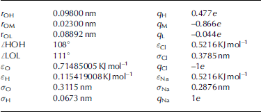
For the water molecule we have used a model with six interaction sites (Reference Nada, van der Eerden and FurukawaNada and van der eerden, 2003). three of these sites are the three atoms of the water, and three sites are point charges. the model is based on a rigid molecular architecture. a point charge m is located on the bisector of the hoh angle. the remaining two charges, l1 and l2, are located on the plane perpendicular to the plane of the atoms and containing the point m. of these six sites, the three atoms interact through a lennard-jones 6-12 potential. the o atom is electrically neutral, the two h atoms carry a positive charge, and m, l1 and l2 carry a negative charge. a detailed description of the model can be found in Reference Nada, van der Eerden and FurukawaNada and van der eerden (2003) and Reference Carignano, Shepson and SzleiferCarignano and others (2005). table 1 summarizes the water geometry and all interaction parameters. for system b, the ions are modeled as a lennard-jones site carrying a unit charge. the total potential energy of the system is
Table 1. Geometric and interaction parameters for the six-site water model and ions. Combination rules are: σij = σi+σj/2 i j , Spherical cut-off is imposed at r = 1 nm, with a switching function acting for r > 0.85 nm. No long-range corrections are applied
Where the sum runs over all the different site pairs corresponding to different molecules.
The melting temperature of the six-site water model was estimated to be 271±9 k (Reference Nada, van der Eerden and FurukawaNada and van der eerden, 2003). this result was obtained by free energy integration using monte carlo simulations. however, in our constant-pressure coexistence simulations, we observe freezing at temperatures as high as 284 k. the simulations presented here were done at 266 k. this corresponds to up to –18˚c of supercooling, close to the (experimental) eutectic temperature for nacl. since complete freezing is achieved in each case, we regard our simulation temperature as being below the eutectic temperature for the model solution that we consider.
Results
A total of twelve trajectories have been simulated, three for each of the cases considered here. the results within each case are consistent with the normal statistical fluctuations of the simulations. we start analyzing our results with the pure-water case, system a. figure 2 shows the average number of ice layers as a function of time for both interfacial planes, prismatic and basal. we discriminate between ice and liquid molecules by calculating a short time average of the number of hydrogen bonds, as explained in Reference Carignano, Shepson and SzleiferCarignano and others (2005). the growth rate is approximately constant for both cases, with the prismatic plane growing faster than the basal plane, aswas previously found for growth in the presence of a free surface. the final configuration has all the molecules forming ice. the resulting growth rate in our simulation is of the order of 50 cms–1 for the prismatic plane and 35 cm s–1 for the basal plane. experimental determinations of ice-growth rates gave values of 10cm s–1 for 15˚c of supercooling (prup-pacher, 1967; Reference Smith, Bryk and HaymetShibkov and others, 2003). these experiments actually measure the tip velocity of a growing ice crystal in a variety of morphologies. our simulations correspond to a planar front. therefore it is only reasonable to expect agreement in the order of magnitude of the growth rate.

Fig. 2. Average number of ice layers (calculated as the number of ice molecules divided by 96, the number of molecules in a layer) as a function of time for system A, when the interface is at the basal plane (solid line) and at the prismatic plane (dashed line). These results are representative of the findings over a set of three trajectories for each case.
The time evolution of the density of the system is displayed in figure 3. the initial density corresponds to the ice/water system, so is a weighted average of the density of the two phases. as the solidification progresses, the density decreases to the value corresponding to pure ice, 920.5 kgm–3. the simulations were done at constant pressure by coupling the system to a parrinello–rhaman semi-isotropic barostat. the compressibility on the direction perpendicular to the interface (z axis) corresponds to the water, while the higher ice compressibility acts on the directions parallel to the interface (x, y axis). therefore, the volume fluctuations are mainly along the z axis.

Fig. 3. The total density of the system as a function of time for system A, when the interface is at the basal (solid line) and at the prismatic (dashed line) plane. The large fluctuations are common to all the simulated trajectories.
It is interesting to note that when the growth is at the basal plane, the new ice tends to show stacking faults, i.e. some of the basal sheets are displaced half a unit cell from the expected position. therefore the new ice has some planes forming cubic ice and some planes forming hexagonal ice. this is a remarkable result, since it is well known that glassy water freezes like cubic ice (Reference Johari, Fleissner, Hallbrucker and MayerJohari and others, 1994), to then slowly relax to hexagonal ice. the water model that we are using is not completely glassy at 266 k, but has a slow mobility as discussed in Reference Carignano, Shepson and SzleiferCarignano and others (2005). in figure 4 we show a typical final configuration of the system, where several stacking faults are visualized. this fault formation is also observed in the simulations of system b, with ions.

Fig. 4. On the left side of the figure the initial ice remains in the original hexagonal conformation, characterized by the zigzag of the path from cell to cell. The new ice, on the right, grows forming chunks of cubic ice. This behavior is also observed when ions are present in the solution. The line indicates the stacking faults.
System b contains three ion pairs. the interaction parameters for these ions are given in table 1. the use of these parameters is justified by the ion–water pair distribution functions in liquid water, which reasonably agree with experimental and previous simulation results.
The growth rate found for system b is smaller than that corresponding to the same temperature for system a. the number of molecules in the ice phase as a function of time is displayed in figure 5 for two representative trajectories for the basal and prismatic planes. a simple explanation for the lower rate is that the presence of the ions depresses the freezing point, and then the degree of supercooling is smaller in the salty system than in the pure water system. it is interesting to note that the initial growth is faster in the prismatic plane than for the basal plane. then, at intermediate times, the growth on the prismatic plane stops and the system remains in a metastable state for approximately 2 ns. this behavior was reproduced in different trajectories, but the duration of the metastable state is different for every trajectory, the longest being 5 ns. for all the analyzed trajectories, the metastable state was reached in approximately 2.5 ns, which corresponds to the growth of four new ice layers. this time is likely to be a characteristic of the simulation cell, and related to the number of molecules in liquid state remaining in the system (see below). in order to understand this behavior, we calculated all the inter-ion distances as a function of time. careful examination of these distances reveals that complete freezing is only achieved when all the ions in the system are paired, or forming clusters. this pairing or clustering reduces the entropy of the liquid phase, allowing the crystallization.

Fig. 5. The average number of ice layers as a function of time for the basal plane (solid line) and prismatic plane (dashed line). The total growing time is in both cases longer than the corresponding time for system A (see Fig. 2). The basal system, however, grows at a nearly linear rate at all times. The prismatic system gets trapped in a metastable state with a duration that is different for different trajectories.
The question that arises is why there is a metastable state when the interface is at the prismatic plane, but not when the interface is at the basal plane. a speculative answer follows from the different mechanism of ice formation on both planes. as has been previously reported (Reference Nada and FurukawaNada and furukawa, 1996; Reference Carignano, Shepson and SzleiferCarignano and others, 2005), the growth on the basal plane is by a layer-by-layer mechanism, while on the prismatic plane it is disorganized but faster. these two different mechanisms result in a smooth ice/water interface on the basal plane during the growth, but a rough interface
For the prismatic plane. the rough interface offers many spots where the ions may temporarily bond, delaying in this way the pairing with the other ion. our system is not large enough to account for this delay in an average way, and thus our simulation yields a metastable state whose duration depends on the particular trajectories. this explanation is plausible, but still needs to be proven with more calculations.
Two typical final configurations for system b are displayed in figures 6 (prismatic) and 7 (basal). we draw two main conclusions from these figures. first, the ice is perfect hexagonal ice in all the prismatic systems except for the small perturbations next to the ions. for the basal interface, system b also exhibits stacking faults in the final configuration as does system a. the second conclusion is that the ions are always participating in a cluster formation. in one case (fig. 6), the six ions form three ion pairs. in the other case (fig. 7), the ions form two clusters, each with three atoms. a full characterization of the final structure of the ions requires a much bigger system than the one that we have simulated. however, our results consistently show cluster formation, and no isolated ions were found in the final state for all the trajectories analyzed.

Fig. 6. Typical final configuration for system B with the interface at the prismatic plane. There are no defects in the ice in this case, except for small perturbations near the ions. All the ions in this case participate in a pair at the point of freezing.

Fig. 7. Final configuration of system B, with basal interface. In this case, the ions form two similar clusters. The line indicates the stacking faults common to all simulations with basal interface. In all the trajectories that we have studied for system B, there were no isolated ions at the end of the simulation.
Conclusions
We have presented a md simulation study of the ice growth from supercooled water and brine. this is the first study where hexagonal ice is grown from a brine solution. our results indicate that in the pure-water systems, ice growth is faster on the prismatic face of the ice than on the basal plane. for ice growth from salt solution, ion pairing and clustering plays an important role in the crystallization process and rates. two main effects are observed. first, the ions delay the solidification process on both types of interfaces studied. second, when the interface is at the prismatic plane, ion pairing competes with adsorption of the ions to the rough growing ice/water interface. in all cases studied for growth on the basal plane, the resulting ice displays a number of stacking faults forming small portions of cubic ice. on the other hand, when ice grows on the prismatic plane, the new ice is perfect hexagonal ice. we believe that the requirement for ion pairing to form ice is due to the very large gain in free energy of solvation in the liquid water that prevents the formation of ice with individual ions. the reduction of electrostatic energy by ion pairing enables a more suitable environment for the formation of ice.
This is an initial simple approximation to a microscopic description of the complex problem of sea-ice formation. the next steps should include other important ingredients present in this process, such as heat flux upon freezing and convection effects. work in this direction is in progress.
Acknowledgements
M.a.c. thanks e.e. avila for interesting discussions during the completion of this work. p.b.s. recognizes support from the us national science foundation (grant no. 0325361-opp).


