Validation for CFD Simulation in Rod Bundles With Split-Vane Spacer Grids Based on LDA Measurement
 Jinbiao Xiong
 Chuan Lu2
  Wenhai Qu
- 1School of Nuclear Science and Engineering, Shanghai Jiao Tong University, Shanghai, China
- 2State Key Laboratory of Reactor System Design Technology, Nuclear Power Institute of China, Chengdu, China
Laser Doppler anemometry (LDA) measurement of axial flow velocity and pressure drop measurement has been carried out in a 5 × 5 rod bundle installed with two split-mixing-vane grids. The measured results are utilized to validate the CFD simulation. The realizable and non-linear k-ε turbulence model is utilized in the CFD computation, while the two-layer wall treatment is employed with both models. Mesh sensitivity investigation shows that the pressure drop is weakly affected by local mesh refinement in the spacer grid, while its effect on the velocity in the near wake of spacer grid is apparent. The validation shows that prediction on the mean axial velocity is relatively poor in the near wake of the spacer grid where the measured result shows relatively smooth distribution of axial velocity. Refinement of mesh in the spacer grid eliminates some peaks for the non-linear model. Comparing with the effect of mesh refinement, the difference caused by the turbulence models is relatively weak in the near wake region. In the far-wake region it is still difficult to judge which model shows definite superiority to the other. For pressure drop, prediction of non-linear k-ε is closer to the experiment.
Introduction
Turbulent flow in the fuel assemblies of nuclear reactors significantly affects heat transfer and pressure drop performances which are the essential factors in the research and design (R&D) of advanced fuel assembly. Computation fluid dynamics (CFD) analysis has been extensively applied in screening and optimizing the design of spacer grid of rod-bundle fuel assembly in pressurized water reactors (PWRs). For example, Ikeda (Ikeda, 2014) utilized CFD analysis in the design of high-efficiency spacer grid to increase the critical heat flux (CHF) performance. It has also been well-recognized that the best practices should be complied with in the CFD analysis to obtain the high-fidelity results (Mahaffy et al., 2014).
In order to understand the flow structure in rod-bundle geometry and to obtain CFD-grade data to validate CFD methodology, numerous experiments on flow measurement in rod bundles have been carried out. Krauss et al. investigated large-scale quasi-periodic fluctuations in the enlarged tight-lattice bundles based on the three dimensional (3D) flow measurement utilizing the hot-wire probe with x-wire (Krauss and Meyer, 1998; McClusky, 2004) employed the particle image velocimetry (PIV) to measure the cross flow induced by split mixing vane in one of the subchannels in the 5 × 5 rod bundle. With their experimental data, Smith III et al. validated their CFD methodology (Smith et al., 2002). Dominguez-Ontiveros et al. (2012) utilized the two-dimensional time-resolved PIV (2D TR-PIV) to measure the flow field in a 5 × 5 rod bundle with spacer grid. With the laser Doppler anemometry (LDA) Conner et al. (2013a) obtained the cross flow in rod bundle with the same configuration as Dominguez-Ontiveros et al.'s. Dominguez-Ontiveros et al.'s and Conner et al.'s experimental data has been included in the CFD benchmark database (Conner et al., 2013b). With the aid of telecentric optic Xiong et al. (2018a) measured the 2D cross flow in a 5 × 5 rod bundle with 2D PIV. More recently, Qu et al. (2019a,b,c) carried out the high-fidelity PIV measurement in rod bundle with split mixing vanes.
For the sake of establishing the best practices for CFD analysis on flow in rod-bundle fuel assembly, two international collaborative CFD benchmark activities, i.e., OECD/NEA KAERI MATiS-H benchmark (Lee et al., 2012), EPRI-NESTOR benchmark (Wells et al., 2015) and IAEA benchmark (Xiong et al., 2018b), have been carried out. Step-by-step experimental activities are on-going in Shanghai Jiao Tong University to provide the high-quality CFD validation data. Experimental measurement of turbulent flow in a 3 × 3 rod bundle is first carried out for CFD validation (Xiong et al., 2014a). Following the 3 × 3 rod bundle experiment, the flow field in the 6 × 6 rod bundle installed with simple ring-type grids is measured with the LDA and utilized for CFD validation (Xiong et al., 2014b). In this paper, the turbulent flow in the 5 × 5 rod bundle is measured in the downstream of spacer grid with split-type mixing vanes using the LDA. The CFD methodology is validated based on the experiment result.
Experiment
Hydraulic Facility and Test Section
The flow measurement experiments have been carried out on the MEdium-Scale Hydraulic (MESH) facility in Shanghai Jiao Tong University which is shown in Figure 1. In the test facility two parallel pumps supply the water flow rate as high as 225 m3/h. The bypass line is utilized to adjust the flow rate through the test section line. The flow meter with measurement error <1% is installed on the test section line to measure the flow rate. A heat exchanger is installed to remove the pump heat from the main loop.
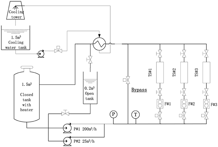
Figure 1. Schematic of test facility utilized in the experiment (Xiong et al., 2014b).
Figure 2 shows the vertical cross-sectional and three-dimensional (3D) view of 5 × 5 rod bundle test section in which the 9.5 mm-in-diameter rods are squarely arrayed with the pitch of 12.6 mm. The rod bundle, 1,156 mm in length, is vertically installed in the housing channel which has the inner dimension of 65 × 65 mm. A honeycomb flow straightener, 50 mm in height, is installed upstream of the rod bundle, in order to remove the upstream effect of elbow and adapter and to achieve relatively uniform flow distribution in the cross section. On the bottom support plat of rod bundle the circular and oval holes are drilled to distribute the flow more uniformly across the rod bundle. The cone-shaped bottom end is manufactured on each rod to facilitate assembling. In the rod bundle two spacer grids with split mixing vanes, 33 mm in height, are installed. Z = 0 is defined on the top surface of bottom support plate. The first spacer grid locates 410 mm above the bottom support plate, i.e., Z = 410 mm. The distance between the first and second spacer grid is 300 mm. Upstream and downstream of the first spacer grid one measurement window is fabricated, respectively. Both windows are 65 × 120 mm in size. Downstream of the second spacer grid the acrylic channel is utilized. On the top of the test section a water tank is installed where water flows away from the three circumferential outlets.
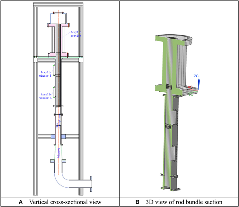
Figure 2. Geometry of the rod-bundle test section. (A) Vertical cross-sectional view. (B) 3D view of rod bundle section.
Velocity and Pressure Measurement
The pressure drop over the span of the first spacer grid is measured between Z = 344 and 677mm with the differential pressure transducer YOKOKAWA EJA110A. The five-beam Dantec FiberFlow Laser Doppler Anemometry (LDA) is employed for flow measurement. However, due to the blockage of rods, only the axial velocity component is measured with the green laser (λ = 514.5 nm). The 5 μm Dantec polyamide particle, 1.03 g/cm3 in density, is utilized as the seeding particle. At each sample point the measurement is stopped when either of the two conditions is satisfied, i.e., the maximum number of samples reaches 5,000 or the sampling time is 60 s. Axial velocity is measured over two cross sections upstream of the first spacer grid, i.e., Z = 165 and 205 mm and over three cross sections downstream of the first spacer grid, i.e., Z = 460, 490, and 520 mm. The downstream cross sections are, respectively 2.54Dh, 5.08Dh, and 7.62Dh downstream of the spacer grid. The measured points on each cross section are shown as black dots in Figure 3. There are nine measuring lines and 45 measuring points on each line.
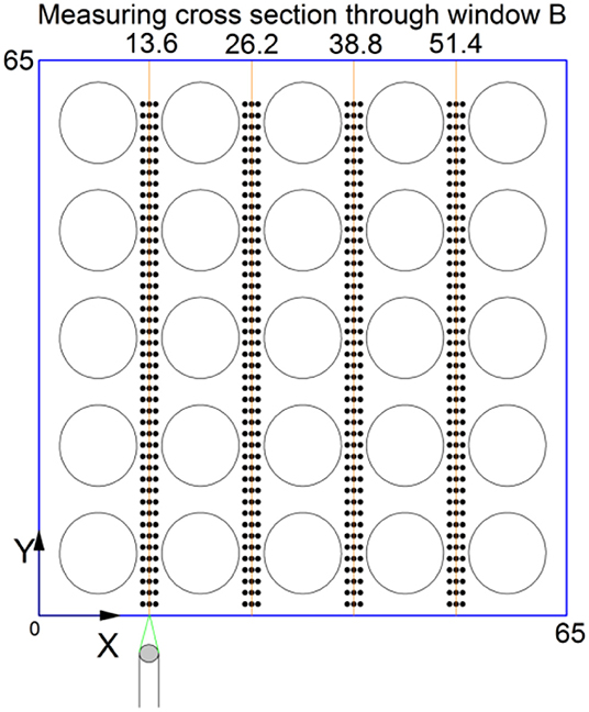
Figure 3. Measuring position in the cross section downstream of the first spacer grid.
Figure 4 presents an example of measured instantaneous velocity samples at one of the measuring positions. Based on the instantaneous velocity, the mean velocity is derived via
where the transit time weighting is utilized. N is the number of valid samples; wi is the ith instantaneous axial velocity; Δti is the transit time through the measurement volume of the ith sampled particle. The transit time weighting is also used while deriving the root mean square of fluctuating velocity, i.e.,
where .
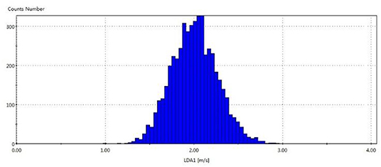
Figure 4. Example of sampled velocity distribution.
Error Estimation
Several sources of error have been recognized in LDA measurement.
Type 1: Velocity bias, i.e., more high velocity particles are sampled than the low velocity ones. This type of error is minimized by introducing transit time weighting method, which has been introduced above.
Type 2: Misalignment of the laser beams can lead to non-uniform spacing of fringe model. This error is mitigated by alignment with a pin-hole which is 50 μm in diameter.
Type 3: Velocity gradient bias resulted from velocity gradient in the measurement volume. While using the lens with focal length of 310 mm, the measurement volume of LDA is an ellipsoid whose axis lengths are 50, 800, and 50 μm, respectively. For two-dimensional flows the error of mean velocity caused by velocity gradient bias can then be quantified as follows
Type 4: Uncertainty due to limited sampling number. The 95% confidence bound of mean velocity can be estimated with
while the 95% confidence bound of RMS velocity can be calculated with
The velocity gradient bias is proportional to the measurement volume size and the second derivatives of velocity. However, quantification of the bias is difficult since lack of data on the second derivatives. Here, we take the 95%-confidence-bound uncertainty as the error bound.
Experiment Results
The experiment is carried out at the bulk velocity of 3 m/s. The temperature in the test section is 21°C. The Reynolds number is 3.6 × 10⁴. The axial velocity is measured from both windows. Figure 5 compares the measured axial velocity at two cross sections upstream of the first spacer grid, i.e., Z = 165 mm (14 Dh) and 205 mm (17.4 Dh), with the data obtain by Chang et al. (2012) who measured the flow in the cross section 90 Dh downstream of the spacer where the flow can be regarded as fully developed. The comparison shows that our measured data on the plane Z = 205 mm matches with Chang et al.'s fully developed data. In the fully developed condition the velocity distribution become even more non-uniform. There is an apparent peak of axial velocity in the center of wall subchannel when the flow is fully developed. Due to the higher velocity, the turbulence intensity in the wall subchannel becomes stronger due to turbulence production in the vicinity of wall. In the contrast the turbulence intensity in the inner subchannel is weaker in the full developed condition. The estimated error is also shown in Figure 5. We can see that the mean velocity has been well-measured while the uncertainty of the RMS velocity is relatively large.
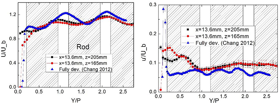
Figure 5. Comparing the present result with Chang et al.'s data (Chang et al., 2012).
Through the upper window which is downstream of the first spacer grid axial velocity is measured on the three horizontal planes. The measured mean and RMS velocity are shown in Figures 6, 7. Apparent similarity has been observed between the first and third measured zones and between the second and fourth measured zones. The disturbance by the spacer grids decays in the plane further from the spacer grid. However, its effect is still remarkable on the plane Z = 515 mm. The uncertainty of mean velocity is large at the positions where y is large. It is resulted from the low sampling data rate when the measured position is far away from the visualization window. However, the largest relative error is estimated to be within 2%.
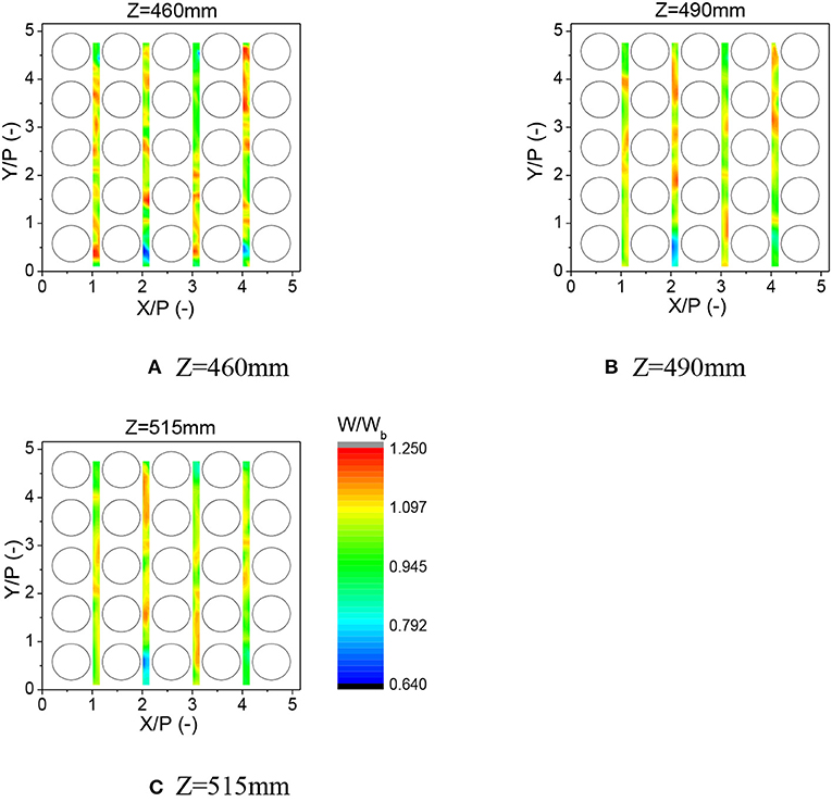
Figure 6. Evolution of axial mean velocity distribution downstream of the mixing-vane spacer grid (Re = 3.6 × 10⁴). (A) Z = 460 mm. (B) Z = 490 mm. (C) Z = 515 mm.
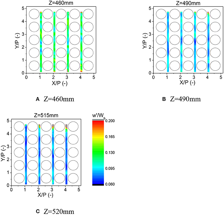
Figure 7. Evolution of axial root mean square velocity distribution downstream of the mixing-vane spacer grid (Re = 3.6 × 10⁴). (A) Z = 460 mm. (B) Z = 490 mm. (C) Z = 520 mm.
CFD Validation
Based on the continuous validation efforts, Westinghouse and AREVA developed their best practice guidelines (BPGs) for CFD simulation of flow in rod-bundle fuel assembly. Conner et al. summarized the Westinghouse best practices in reference (Conner et al., 2015), including the recommendation for mesh size and model selection. Martin et al. (2015) presented AREVA's best practices in the EPRI-NESTOR benchmark, which includes utilization of a modified quadratic k-ε model, trimmed mesh with the base size of 0.3 mm and two prism layers which guarantee the y+ is around 65 in the majority of the domain. CD-adapco validated their best practices for rod-bundle flow simulation in the EPRI-NESTOR benchmark in which Brewster et al. (2015) used a hex-dominated trimmed cell mesh with the base size of 0.3 mm and the constraints of 0.075 mm minimum mesh dimension. Brewster et al. (2015) selected a high y+ implementation of non-linear quadratic k-ε turbulence model with standard wall function.
In this study the CFD computation is carried out with STAR CCM+. As shown in Figure 8A, the computation domain is 996 mm in height and includes two spans of spacer grid. The inlet boundary of domain locates 315 mm upstream of the first spacer grid, while the outlet boundary is 315 mm downstream of the second spacer grid. The realizable k-ε model and the non-linear (quadratic) k-ε model are validated. At the inlet boundary the uniform velocity distribution is assumed, while the outlet boundary is pressure-outlet type. On the wall boundary the two-layer wall treatment is utilized which blends a one-equation model with the two-equation k-ε model. The one-equation model is activated in the vicinity of the wall and solves for k, while ε is algebraically calculated according to the distance from the wall. The second-order upwind scheme is utilized for the convection term of all the equations.
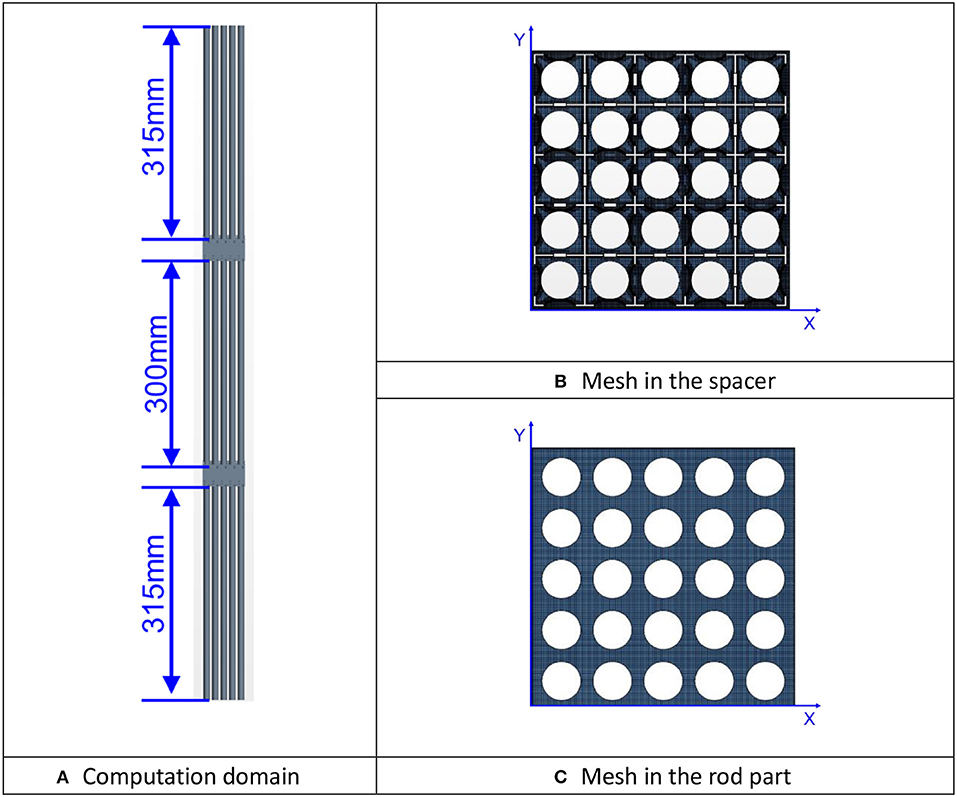
Figure 8. The computation domain and the cross section of mesh. (A) Computation domain. (B) Mesh in the spacer. (C) Mesh in the rod part.
Mesh Sensitivity
The meshing strategy of trimmed mesh with prism layer is employed for the region of spacer grid, while the extruder is utilized to generated the mesh in the bare rod parts. In order to improve mesh quality, the dimples and springs on the spacer grid have been extruded out to avoid the unacceptable narrow gaps where the spacer grid contacts the rods. Exactly the same meshing parameters have been configured for the two spacer grids. In order to generate conformal mesh at the interface while extruding the mesh, the periodic interface is utilized for the mesh solver. The cross-sectional view of mesh in the spacer grid and rod bundle section are shown in Figures 8B,C. Two meshes are utilized to show the mesh sensitivity. The major difference between the two meshes in the spacer grid part.
The overall configuration of two meshes are collectively given in Table 1. According to the recommendation by AREVA and CD-adapco, the base size which controls the bulk flow mesh size is set as 0.3 mm. The prism layer on the wall surface affects y+ value which can affect the applicability of wall treatment or function. Since the two-layer wall treatment is utilized in the computation, the value of y+ at first wall cell should avoid the transition of the two layer (y+ ≈ 11.3) because the accuracy of two-layer model is relatively poor there. Here one prism layer is utilized. The thickness of prism layer is 0.045 and 0.075 mm, respectively for two meshes. Comparing with the mesh #2, the mesh #1 also significantly refined the surface mesh size on the spacer grid which will leads to much finer mesh near the spacer grid surface. The cell number in mesh #1 is 96 million, and 36 million in mesh #2.
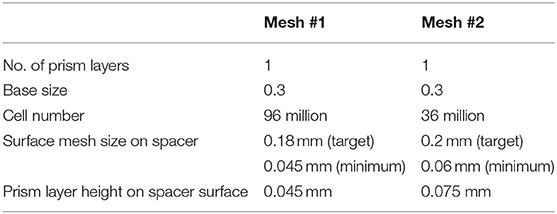
Table 1. Configuration of mesh for sensitivity analysis.
Figure 9 presents the sensitivity of pressure drop on mesh refinement in the section of spacer grid. We can see that the influence of mesh refinement on the pressure drop is generally negligible and mainly observed in the bare rod part near the inlet. The effect of mesh refinement on the velocity is much more pronounced, as shown in Figure 10. However, such effect decays in the far downstream. It is also observed that the non-linear k-ε model shows stronger sensitivity on mesh refinement than the realizable k-ε model.
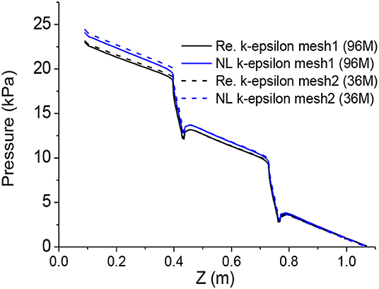
Figure 9. Mesh sensitivity on pressure drop along the line (X, Y) = (0,0).
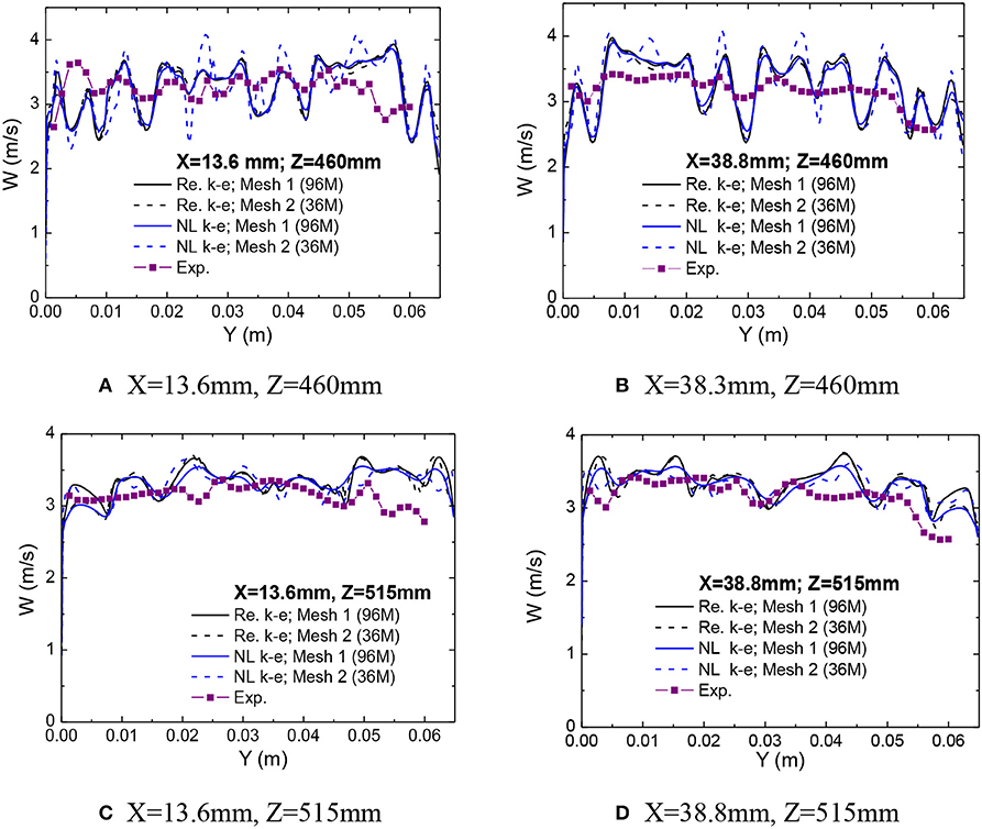
Figure 10. Validation of the computed axial velocity. (A) X = 13.6 mm, Z = 460 mm. (B) X = 38.3 mm, Z = 460 mm. (C) X = 13.6 mm, Z = 515 mm. (D) X = 38.8 mm, Z = 515 mm.
Velocity
Since only the axial flow velocity component is measured, direct comparison on the turbulence intensity is not possible here. Hence, the measured axial velocity is compared in Figure 10. The comparison is carried out along the line x = 13.6 and 38.3 mm on the two measuring planes, i.e., Z = 460 and 515 mm. From Figure 10, we can see that the prediction on the mean axial velocity is relatively poor in the cross section closer to the spacer grid, i.e., Z = 460 mm. In Figure 10B the computations show more small-scale flow structures while the measured result shows relatively smooth distribution of axial velocity. It should be noted that the refinement of mesh in the spacer grid eliminates some peaks for the non-linear model, which emphasize the importance of mesh quality in the complex geometry. Fortunately, such effect only signifies in the near wake of spacer grid. It should also be noted that the measurement volume of LDA is an ellipsoid in which the long axis is about 1 mm and the short axis is about 0.05 mm. Hence, the obtained velocity is average value in the measurement volume. Hence, the local variation can be smeared in the LDA measurement. Comparing with the effect of mesh refinement, the difference caused by the turbulence models is relatively weak in the near wake region. In the far-wake region it is still difficult to judge which model shows definite superiority to the other.
The cross flow is of great interest for inter-subchannel mixing analysis. The predicted cross flow downstream of the two spacer grids is shown in Figure 11. We can see that the vortices can be predicted with the non-linear k-ε model. A pair of small vortices appear in the diagonal of the subchannel which merges into a big one in the downstream. And the intensity of cross flow decays from 5Dh to 25Dh downstream of a spacer grid. Comparing the cross flow downstream of 1st and 2nd spacer grids, we can observe negligible difference, which implies little effect of upstream flow condition on the flow downstream of spacer grid.
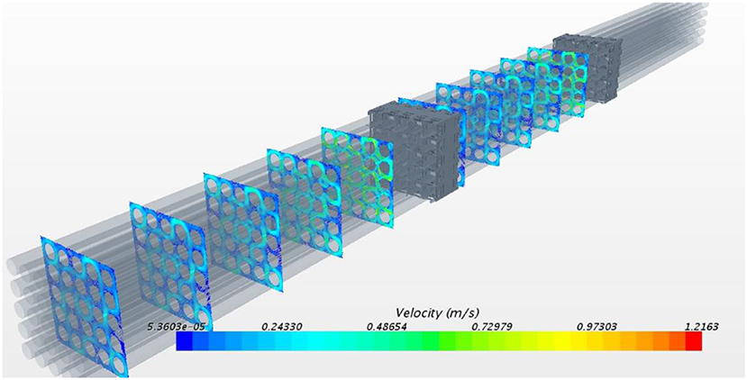
Figure 11. Predicted cross flow with non-linear k-ε model at 5Dh, 10Dh, 15Dh, 20Dh, 25Dh downstream of spacer grid.
Pressure Drop
Pressure drop is an important factor to consider when evaluating design of spacer grid, and hence an important parameter to predict with the CFD simulation. The calculated pressure drop with different models and different meshes are compared with the experiment measurement in Figure 12. The mesh refinement in the spacer grid region shows weak effect on pressure drop (2% to 4%). However, refinement of mesh reduces the pressure drop for both models. We can see that the non-linear k-ε predicts the pressure drop close to the experiment, when the mesh is refined.
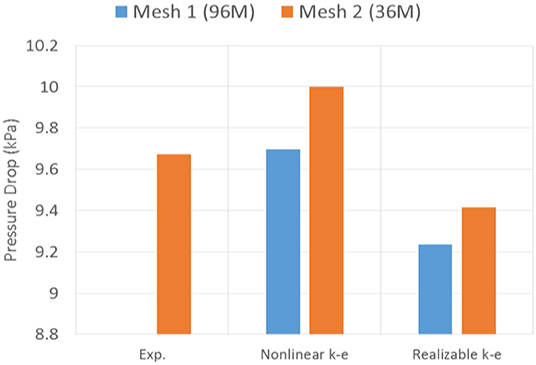
Figure 12. Comparison on pressure drop prediction.
Conclusion
The flow field is measured in a 5 × 5 rod bundle installed with split-type mixing vane grids with laser Doppler anemometry (LDA) downstream of the spacer grid. The measured results are utilized to validate the CFD simulation based on the commercial CFD code, Star-CCM+. The realizable and non-linear k-ε turbulence model is utilized in the CFD computation, while the two-layer wall treatment is employed with both models. The mesh sensitivity investigation shows that the pressure drop is weakly affected by the mesh refinement, while its effect on the velocity is apparent. The validation shows that prediction on the mean axial velocity is relatively poor in the near wake of the spacer grid where the measured result shows relatively smooth distribution of axial velocity. Refinement of mesh in the spacer grid eliminates some peaks for the non-linear model. Comparing with the effect of mesh refinement, the difference caused by the turbulence models is relatively weak in the near wake region. In the far-wake region it is still difficult to judge which model shows definite superiority to the other. For pressure drop, prediction of non-linear k-ε is closer to the experiment.
Data Availability Statement
The datasets generated for this study are available on request to the corresponding author.
Author Contributions
JX carried out the CFD simulation and prepared the manuscript. CL and WQ provided their suggestion on the contents of the manuscript.
Funding
The authors would like to express their gratitude to the fund of National Natural Science Foundation of China (No. 51676120).
Conflict of Interest
The authors declare that the research was conducted in the absence of any commercial or financial relationships that could be construed as a potential conflict of interest.
References
Brewster, R., Carpenter, C., Volpenhein, E., Baglietto, E., and Smith, J. (2015). “Application of CD-adapco best practices to NESTOR OMEGA MVG benchmark exercises using STAR-CCM+,” in The 16th International Topical Meeting on Nuclear Reactor Thermal Hydraulics (NURETH-16) (Chicago, IL). p. 13164.
Chang, S. K, Kim, S., and Song, C. H. (2012). “OECD/NEA—KAERI rod bundle CFD benchmark exercise test,” in 4th OECD/NEA-IAEA Workshop Experimental Validation and Application of CFD and CMFD Codes in Nuclear Reactor Technology (CFD4NRS-4) (Daejon).
Conner, M. E., Dominguez-Ontiveros, E. E., and Hassan, Y. A. (2013a). “Advanced hydraulic benchmark data for PWR mixing vane grid,” in The 15th International Topical Meeting on Nuclear Reactor Thermal-Hydraulics (Pisa). p. NURETH15–039.
Conner, M. E., Hassan, Y. A., and Dominguez-Ontiveros, E. E. (2013b). Hydraulic benchmark data for PWR mixing vane grid. Nucl. Eng. Des. 264, 97–102. doi: 10.1016/j.nucengdes.2012.12.001
Conner, M. E., Karoutas, Z. E., and Xu, Y. (2015). “Westinghouse CFD modeling and results for EPRI NESTOR CFD round robin exercise of PWR rod bundle testing,” in The 16th International Topical Meeting on Nuclear Reactor Thermal Hydraulics (NURETH-16). (Chicago, IL). p. 13601.
Dominguez-Ontiveros, E. E., Hassan, Y. A., Conner, M. E., and Karoutas, Z. (2012). Experimental benchmark data for PWR rod bundle with spacer-grids. Nucl. Eng. Des. 253, 396–405. doi: 10.1016/j.nucengdes.2012.09.003
Ikeda, K. (2014). CFD application to advanced design for high efficiency spacer grid. Nucl. Eng. Des. 279, 73–82. doi: 10.1016/j.nucengdes.2014.02.013
Krauss, T., and Meyer, L. (1998). Experimental investigation of turbulent transport of momentum and energy in a heated rod bundle. Nucl. Eng. Des. 180, 185–206. doi: 10.1016/S0029-5493(98)00158-7
Lee, J. R., Kim, J., and Song, C. H. (2012). “Synthesis of OECD/NEA-KAERI rod bundle benchmark exercise,” in 4th OECD/NEA-IAEA Workshop Experimental Validation and Application of CFD and CMFD Codes in Nuclear Reactor Technology (CFD4NRS-4) (Daejon). p. KN-02.
Mahaffy, J., Chung, B., Dubois, F., Ducros, F., Graffard, E., Heitsch, M., et al. (2014). Best Practice Guidelines for the use of CFD in Nuclear Reactor Safety Applications-Revision. NEA/CSNI/R(2014)11. Organisation for Economic Co-operation and Development.
Martin, M., Keheley, T., Goodheart, K., Hatman, A., and Chatelain, A. (2015). “Validation of AREVA's best practices in the round robin CFD benchmark,” in The 16th International Topical Meeting on Nuclear Reactor Thermal Hydraulics (NURETH-16) (Chicago, IL). p. 13220.
McClusky, H. L. (2004). Mapping of the lateral flow field in typical subchannels of a support grid with vanes. J. Fluid. Eng. 125, 987–996. doi: 10.1115/1.1625688
Qu, W., Wang, Z., Xiong, J., and Cheng, X. (2019a). Experimental study of cross flow and lateral pressure drop in a 5 × 5 rod bundle with mixing vane spacer grid. Nucl. Eng. Des. 353:110209. doi: 10.1016/j.nucengdes.2019.110209
Qu, W., Xiong, J., Chen, S., and Cheng, X. (2019b). High-fidelity PIV measurement of cross flow in 5 × 5 rod bundle with mixing vane grids. Nucl. Eng. Des. 344, 131–143. doi: 10.1016/j.nucengdes.2019.01.021
Qu, W., Xiong, J., Chen, S., Qiu, Z., Deng, J., and Cheng, X. (2019c). PIV measurement of turbulent flow downstream of mixing vane spacer grid in 5 × 5 rod bundle. Ann. Nucl. Energy 132, 277–287. doi: 10.1016/j.anucene.2019.04.016
Smith, L. D., Conner, M. E., Liu, B., Dzodzo, B., Paramonov, D. V., Beasley, D. E., et al. (2002). “Benchmarking computational fluid dynamics for applicatoin to PWR fuel,” in 10th International Conference on Nuclear Engineering (Arlington, VA). p. ICONE10–22475.
Wells, D. M., Peturaud, P., and Yagnik, S. K. (2015). “Overview of CFD round robin benchmark of the high fidelity fuel rod bundle NESTOR experimental data,” in The 16th International Topical Meeting on Nuclear Reactor Thermal Hydraulics (NURETH-16) (Chicago, IL). p. 13173.
Xiong, J., Cheng, R., Lu, C., Chai, X., Liu, X., and Cheng, X. (2018b). CFD simulation of swirling flow induced by twist vanes in a rod bundle. Nucl. Eng. Des. 338, 52–62. doi: 10.1016/j.nucengdes.2018.08.003
Xiong, J., Qu, W., Wu, Z., and Cheng, X. (2018a). PIV measurement of cross flow in a rod bundle assisted by telecentric optics and matched index of refraction. Ann. Nucl. Energy 120, 540–545. doi: 10.1016/j.anucene.2018.06.024
Xiong, J., Yu, Y., Yu, N., Fu, X., Cheng, X., and Yang, Y. (2014b). Experimental investigation on anisotropic turbulent flow in a 6 × 6 rod bundle with LDV. Nucl. Eng. Des. 278, 333–343. doi: 10.1016/j.nucengdes.2014.08.004
Keywords: rod bundle, split-type mixing vane, Laser Doppler anemometer (LDA), CFD validation, two-equation turbulence model
Citation: Xiong J, Lu C and Qu W (2020) Validation for CFD Simulation in Rod Bundles With Split-Vane Spacer Grids Based on LDA Measurement. Front. Energy Res. 8:43. doi: 10.3389/fenrg.2020.00043
Received: 10 January 2020; Accepted: 03 March 2020;
Published: 24 March 2020.
Edited by:
Mingjun Wang, Xi'an Jiaotong University, ChinaReviewed by:
Xiaochang Li, Harbin Engineering University, ChinaMuhammad Saeed, East China University of Technology, China
Copyright © 2020 Xiong, Lu and Qu. This is an open-access article distributed under the terms of the Creative Commons Attribution License (CC BY). The use, distribution or reproduction in other forums is permitted, provided the original author(s) and the copyright owner(s) are credited and that the original publication in this journal is cited, in accordance with accepted academic practice. No use, distribution or reproduction is permitted which does not comply with these terms.
*Correspondence: Jinbiao Xiong, xiongjinbiao@sjtu.edu.cn