Design and Analysis of Commercially Viable Free-Space Optical Communication Link for Diverse Beam Divergence Profiles
 Harjeevan Singh1
  Rajan Miglani
 Gurjot Singh Gaba
- 1Department of Electronics and Communication Engineering, University Institute of Engineering, Chandigarh University, Mohali, India
- 2School of Electronics and Electrical Engineering, Department of Electronics and Communication Engineering, Lovely Professional University, Phagwara, India
- 3School of Computer Science, Mohammed VI Polytechnic University, Ben Guerir, Morocco
- 4Department of Computer Science, College of Computers and Information Technology, Taif University, Taif, Saudi Arabia
With an exponential increase in the use of smart devices and with increasing demand for high-speed data applications, the Radio Frequency and Microwave links will find themselves almost incapable of meeting this deficit. Free-space optical (FSO) links are poised to take the leading role as communication systems for futuristic needs in providing cost-effective and high-speed connectivity to end-users. However, on the flip side, the reliability of FSO links has an intrinsic relationship with the characteristics of the atmospheric channel. During the propagation, the atmospheric adversities result in the geometrical spreading of the FSO beam which in turn has consequential degrading effects on the link performance. In this work, an FSO communication system based on practical, commercial, and realistic parameters has been proposed with the intent of accurately determining the co-relation between different beam divergence profiles and overall link performance. For different beam divergence profiles, the proposed link has been evaluated for reference bit error rate (BER) of 10–9 which is an ideal condition for delivering high-speed data access to the end-users. During the analysis, the practical constraints related to the trade-off between the maximum possible link range and beam divergence have also been optimized. The findings of this work will be crucial for engineers and designers in configuring FSO links for improved link range and reliability.
Introduction
Different multimedia applications have exploded their popularity in recent years, generating massive amounts of mobile data and requiring high data-rate wireless access networks. Systems having a large capacity, high security, very little latency, incredibly low consumption of power, massive interconnection of devices and optimal quality of experience (QoE) are all features of the next 5G technology [1]. In particular, 5G communication envisions ultra-dense heterogeneous networks that allow for hundreds of times more wireless device connectivity and transmission rate than existing wireless networks. As a result, backhaul connectivity having high-capacity is necessary for 5G and beyond networks to provide low end-to-end delays, less consumption of power, and access networks having high speed and high-density levels. In addition to this, it has become very difficult to manage an enormous volume of data for 5G mobile connectivity, necessitating the deployment of robust communication networks to ensure the quality of service (QoS) for various users [2]. The use of radio frequency (RF) in wireless communications is widely accepted, even though spectrum resources are limited. The Internet of Things (IoT) is a concept that enables resource sharing, monitoring, sensing, and real-time-based communications in a vast network of smart devices for business, industrial, social and medical purposes [3–6]. The rapid rise of the Internet of Everything (IoE) or Internet of Things (IoT) technologies has resulted in an exponential rise in the count of physical smart devices, which are connected to the internet [7, 8]. As a result, IoT devices produce a massive quantity of user data, and managing such a huge amount of data is a challenging task. It is expected that the existing available electromagnetic frequency range will be insufficient to fulfill the bandwidth requirements of 5G mobile networks and serve the massive requirements of the IoT paradigm as well. In addition to this, the existing RF technology has a limited spectrum range, as well as restrictions due to regulations regarding the usage of the frequency spectrum and a high amount of interference from other frequency signals. Moreover, the RF sub-bands of the frequency spectrum are currently fully utilized by cellular operators, television transmission, and microwave-based communication links. Researchers are looking into millimeters and nanometer waves, for providing high-speed wireless services, as an alternative to RF-based wireless networks due to the disadvantages of RF-based wireless networks. As a result, in the context of communication-based on optical wireless links, the academician and researchers have diverted their attention towards the license-free optical wireless transmission as a potential substitute of RF technology for highly dense future networks having huge capacity. FSO technology is capable of fulfilling the requirements of enormous bandwidth and high data rates of future generation mobile networks having diverse notable qualities such as very less consumption of power, low cost, less latency, high data transmission rates, and broad frequency spectrum [9].
Unlike RF carriers, which are limited in their spectrum utilization, optical carriers do not need any license for transmission, making them an appealing option for applications having requirements of high network capacity and large bandwidth. FSO technology uses high-frequency optical carrier signals to send data from transmitter to receiver through atmospheric medium [10]. To transmit the information signal successfully, the line of sight (LOS) condition is essential for the FSO transmitter and receiver [11]. Because of its exceptionally high transmission rates, high security of data signal, bandwidth, reduced equipment dimensions (1/10th of the diameter of RF-based antenna), lesser consumption of power (almost half of RF technology), license-free transmission, easy installation, and the huge amount of bandwidth [12, 13], FSO technology is considered to be the upcoming frontier for broadband links having ultra-speed. It works in the visible and infrared range and offers LOS communication because of its narrow signal beamwidth [14]. The basic operating principle of FSO communication is identical to optical fibers-based communication, except that instead of using a directed optical fiber, the modulated data signal is transferred through an unguided channel. The earliest development of FSO communication began approximately 50 years ago for applications based on the space and defense sector when the US military employed sunlight-powered devices to relay telegraph signals from one location to another. Alexander Graham Bell developed the first wireless telephone system in 1876 through conversion of the sound signal to an electrical signal and transmitting this voice signal over a distance of a few feet and the sunlight acted as a carrier signal for this voice transmission. This telephone system became the first wireless telephone system in the world, and it was given the name of “photo-phone.” FSO technology advanced significantly after Hughes Research Laboratories of Malibu, California developed the first operational laser [15].
FSO has become increasingly important for several terrestrial applications during the last decade. Figure 1 illustrates the design of the terrestrial FSO system, installed on the top of two buildings. FSO can also be used for connecting Local Area Networks (LANs), Metropolitan Area Networks (MANs), providing backhaul network support for mobile wireless networks, and communication systems based on optical fibers. Despite these benefits, the performance of FSO communication links is strongly influenced by atmospheric weather conditions [14]. The FSO signal gets absorbed and scattered due to suspended tiny particles of the atmospheric channel like smoke particles, dust particles, aerosols, and haze particles [16]. In addition to these, the FSO signal also gets attenuated due to atmospheric conditions like fog, rain, snow, turbulence, etc. As a consequence of these atmospheric channel conditions, the availability of the FSO link suffers a lot and the FSO link might become unavailable in case of severe weather conditions. Hence, the atmospheric conditions limit the performance of FSO links and are one of the major hurdles faced by these optical wireless communication links.
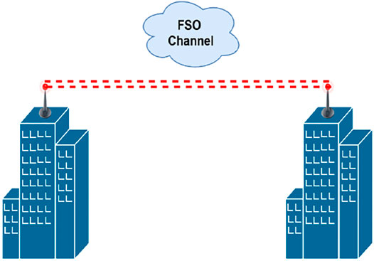
FIGURE 1. Schematic of terrestrial FSO system.
The rest of the paper has been structured as follows: The previous literature related to the divergence of FSO signal along with the contribution of this study will be explained in Related Work and Research Motivation. The mathematical model for explaining the phenomenon of beam divergence of the FSO signal will be discussed in Mathematical Modeling of Beam Divergence. In System Design, we have discussed the system design of the FSO communication system based on practical and commercial FSO link parameters. The results and discussions regarding the influence of divergence of the FSO beam on the performance characteristics of the designed FSO system will be elaborated in Results and Discussions. On the other hand, the conclusion of this study will be discussed in Conclusion.
Related Work and Research Motivation
In addition to atmospheric losses of FSO signal due to absorption, scattering, and other dynamic conditions of the atmosphere, the optical beam also suffers from the limitation of beam divergence as it propagates towards the receiver end. Consequently, the receiver of the FSO system will not be able to receive a portion of the transmitted FSO beam, resulting in beam divergence loss. The authors in [17] have analyzed the beam divergence of the FSO signal and concluded that the diffraction at the receiver aperture causes divergence of the optical beam as the optical signal travels through the atmospheric medium. Unless the receiver collecting aperture is expanded or receiver diversity is used, the attenuation losses due to beam divergence increase as the link length increases. Similarly, the degradation of the FSO signal due to beam divergence has been highlighted in [18] and it has been recommended that the divergence of the FSO beam must have a good match with the telescope’s field of view at the receiver to minimize the beam divergence losses. The authors in [19] have flagged the highly dynamic nature of the atmospheric channel and concluded that it is not feasible to control the atmospheric attenuation of the FSO signal. On the other hand, beam divergence is one of the parameters that can be controlled for improving the performance of the FSO link. The power loss of the FSO signal due to beam divergence has been discussed in [20] and it has been concluded that the beam divergence limits the operating range of the FSO signal. Hence, the beam divergence angle should be controlled carefully during the installation of FSO links, so that the power of the FSO signal should not fall drastically with the transmission distance as a result of the spreading of the FSO signal. Furthermore, the wider angle of beam divergence has been suggested in [21] for short-range based FSO links for removing the misalignment errors. Similarly, the dependence of the geometrical losses on the beam divergence angle has been elaborated in [22, 23] and it has been concluded that the geometrical losses should be reduced by controlling the beam divergence losses so that the total overall attenuation of the FSO signal should be minimized. On the other hand, the precise pointing mechanism has been suggested in [24] for FSO systems having narrow-angle of beam divergence to maintain the line-of-sight based condition. The authors in [25] have discussed the impairment of the FSO link due to divergence of the FSO signal and suggested the adjustment of beam divergence angle dynamically at the transmitter for increasing the power efficiency of the FSO communication system. In addition to this, it has been recommended that the aperture of the receiver lens should be configured as per the divergence of the FSO beam and the range of the FSO link to increase the efficiency of the power link budget. The authors in [26] have advocated the minimum divergence angle as an important feature of the FSO transmitter. The large divergence angles of the FSO beam have been preferred in [27] for easy and quick installation of the FSO communication system. Additionally, the large divergence angles also allow transmitting more power ensuring the safety of human eyes. The divergence of the FSO beam has been mentioned as one of the major challenges for the long-range FSO communications systems [28].
Therefore, it motivates us to extend the work of analyzing the behavior of FSO system under different beam divergence profiles as follows: 1) To design a typical FSO communication system for a practical, commercial, and real-life-based application scenario, 2) To further examine the effects of different profiles of beam divergence on the performance characteristics of FSO system by considering practical and realistic link parameters of FSO transmission, 3) To estimate the maximum achievable link distances of designed FSO system, corresponding to beam divergence profiles of commercial as well as practical FSO systems, by taking into account the practical limitation of the trade-off between the maximum achievable link range and beam divergence. The findings of this study can contribute significantly in providing recommendations to the communication engineers for estimating the optimal divergence angles and the corresponding maximum feasible ranges of FSO links, during the installation of FSO links.
Mathematical Modeling of Beam Divergence
Beam divergence is an essential aspect in designing FSO communication links for transferring data at high transmission rates. Diffraction of light results in divergence of the optical beam before the receiver aperture. Because the transmitted FSO signal is not completely captured by the receiver of the FSO system, it leads to beam divergence loss and results in the loss of information signal. Moreover, these losses increase significantly as the transmission range of the FSO system is increased. Consequently, a suitable beam divergence profile should be adopted in practical scenarios, and diversity schemes can also be employed for enhancing the performance of FSO links.
It’s worth noting that sky radiance can occur at any time of day or night, and is influenced by the receiver’s height, cloud thickness, air particle concentration, and solar irradiation. The amount of sky radiance, in particular, is substantially determined by the geometrical position of the FSO receiver, earth, and Sun. Because even a minor misalignment between the transceivers of the FSO system can result in failure of the FSO link, controlling the line of sight directivity for FSO beam propagating at a narrow-angle of divergence is critical. Furthermore, the beam wandering effect can induce pointing loss by shifting the transmitted beam out of the propagation path. In any event, aiming inaccuracy can significantly lower the values of received optical power and signal-to-noise ratio, leading to an increased bit error rate (BER) and an increased risk of FSO connection failure. Installation of vibration-free FSO devices must be handled with care, and proper bandwidth control must be maintained to compensate for residual jitter. Particularly at visible wavelengths, pointing inaccuracy restricts the performance of the FSO links as the BER and outage of the FSO link increase significantly. The degree of divergence of the FSO signal, along with the optical beam’s shape, are the significant parameters in assessing the performance efficiency of the FSO links, particularly in terms of link margin. FSO typically employs two kinds of beams: the Gaussian beam and the top-hat beam [19]. The standard Gaussian beam is produced by the laser resonant cavity as a natural consequence. The majority of lasers emit Gaussian beams with point-source spatial properties and the Gaussian beam profile has been suggested for the FSO communications [29]. Single-mode lasers, for example, emit very narrow Gaussian beams, and the single-mode optical fibers connected to such lasers give output that is Gaussian as well.
The intensity of the optical signal reduces to 1/e2 of the maximum value at beam spot radius
Where
Where λ represents the wavelength of the optical beam and
The optical beam’s intensity at a radial distance of r from the optical axis can be defined as follows:
Where
Since the peak value of the Gaussian beam’s optical intensity is twice the value of the average value of intensity and the value of total power is equivalent to the multiplication of area of the beam spot and average intensity, we can define the relationship between the total power of the optical beam
The value of incident power (P) on the circular lens of the receiver having an aperture diameter equal to D at a link range of L is given as follows:
In a practical scenario, due to large values of divergence angle (θ ≥ 1) and radius of beam spot
The propagation loss can be calculated by substituting Eq. 7 into Eq. 9 as follows:
System Design
We have designed the commercial applications-based FSO communication system, considering the practical scenario of FSO transmission. The data is transmitted from the FSO transmitter towards the receiver using a high-frequency laser beam through the atmospheric medium. The modulation of the data signal is achieved with an optical signal, acting as a high-frequency carrier, generated by the laser source before transmission to the receiver of the FSO system. Direct modulation or external modulation techniques are two of the most extensively used modulation techniques. The direct modulation approach takes place within the resonator of the laser, and the modulation of the signal is based on the various changes caused due to various additive input components as they affect the optical signal’s intensity levels [23]. On the contrary, the external modulation process happens outside of the resonator of the laser source, and it is highly dependent on the polarization as well as refractive dualism phenomena. A driver circuit will be used in conjunction with the modulators to control the current flowing through the optical source. Laser diodes are generally more preferable in comparison to light-emitting diodes due to their high monochromatic nature, coherence, and highly directional characteristics. Furthermore, the laser diodes generate optical signals having a fixed relationship of phase between the various points of electromagnetic wave.
As depicted in Figure 2, the designed FSO communication system comprises a transmitter, FSO medium, and a receiver. A bit sequence generator, also known as pseudo-random binary sequence generator (PRBS), is included in the optical transmitter for generating random bit sequences. Following the logical signal generated by the bit sequence generator, the input digital information signal is transformed into the electrical domain by the NRZ pulse generator. The transmitter of the FSO communication system also employs an optical source, which generates a signal in the near-infrared region and it acts as the carrier signal for FSO communication. The Mach-Zehnder modulator is responsible for modulating the electrical signal from the NRZ pulse generator with a high-frequency optical carrier signal generated by the laser source. The transmission of the FSO signal towards the receiver takes place through the free space channel. The designed FSO system is transmitting at an operational wavelength of 1552.5 nm having a transmission power equal to 10 dBm. The FSO signal received at the receiver section is focused on a photodetector, which is further responsible for converting the optical domain to the electrical domain. Avalanche photodiode is the photodetector used in the designed FSO system for detecting the incoming FSO beam. For removing the high-frequency noise components of the FSO signal, a low pass filter has been incorporated in the receiver, and on the other hand, a BER analyzer is used to visualize the received information signal.
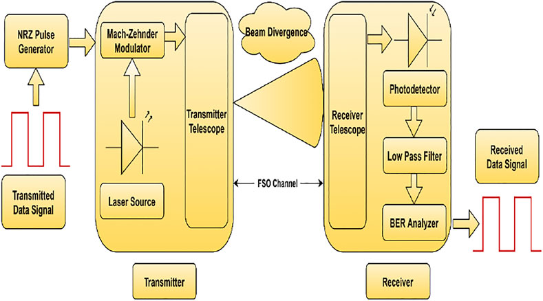
FIGURE 2. Proposed system design of commercial applications-based FSO communication system.
Results and Discussions
The designed system has been configured according to the link parameters of a typically practical and commercial FSO system, specified in Table 1 [17, 20, 32–34]. In addition to this, the link parameters of the designed system have been benchmarked with peer literature for ensuring the proximity to realistic FSO link conditions. The transmission rate of the designed FSO system has been configured as 10 Gbps. In addition to this, the FSO signal’s wavelength of operation has been set to 1552.5 nm for the designed FSO system. The aperture diameter of the transmitter has been set to 5 cm, while the aperture diameter of the receiver is 20 cm.
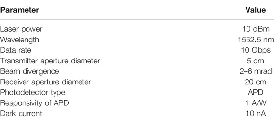
Figure 3 illustrates the optical spectrum of FSO signals at the different stages of signal transmission. The transmission power of the FSO system has been set to 10 dBm and the optical spectrum of the FSO beam after the modulation stage and before the transmission over the FSO channel has been depicted in Figure 3A. The spectrum’s peak signifies that the optical power level of the FSO beam is around 5.75 dBm. After transmission over the FSO signal, the optical spectrum has demonstrated a reduction in signal power. In the case of beam divergence equal to 2 mrad, the optical spectrum has a peak signal power of −24.6 dBm as illustrated in Figure 3B. Furthermore, with an increase in beam divergence from 2 to 4 mrad and 6 mrad, the optical spectrum illustrates a further reduction in signal power as illustrated in Figures 3C,D, respectively.
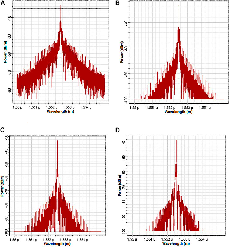
FIGURE 3. Optical Spectrum of designed FSO system: (A) at the transmitter (B) at the receiver (beam divergence of 2 mrad) (C) at the receiver (beam divergence of 4 mrad) (D) at the receiver (beam divergence of 6 mrad).
To further elaborate the FSO signal’s power levels for different beam divergence scenarios, the variation in the received signal power for different link ranges of the designed FSO system has been represented in Figure 4. The received power has witnessed a significant decline as the link distance is incremented from 0.5 to 5 km. On the other hand, the received power is comparatively higher for the FSO system operating with beam divergence equal to 2 mrad as compared to the FSO system operating with a beam divergence of 4 and 6 mrad. For FSO link transmitting at an operating range of 4 km, the received power of the FSO system has been recorded as −26.2, −32.2, and −35.6 dBm corresponding to beam divergence of 2 mrad, 4 mrad, and 6 mrad, respectively. By increasing the divergence of the FSO beam, the receiver of the FSO system is not able to collect enough FSO signal, and consequently, the value of received power decreases. Hence, the beam divergence profile for the FSO link should be controlled so that the reliable detection of the FSO signal is possible at the receiver end.
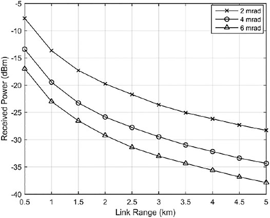
FIGURE 4. Received Power vs. Link Range for different beam divergence scenarios.
The signal-to-noise ratio (SNR) has also witnessed significant variation as the beam divergence of the FSO system is varied, as depicted in Figure 5. SNR is also a significant figure of merit for the FSO system as it defines the levels of the signal power and noise power in the received signal. For the lower beam divergence, the SNR values of the FSO system are satisfactory and the deterioration in the SNR values of the FSO system is observed as the beam divergence increases. The SNR values of the designed FSO system, at an operating range of 4 km, are 16.78, 12.5, and 7.3 dB corresponding to beam divergence values of 2 mrad, 4 mrad, and 6 mrad respectively.
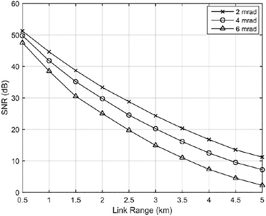
FIGURE 5. SNR vs. Link Range for different beam divergence scenarios.
Figure 6 has illustrated the variation of the quality factor of the FSO system for various scenarios of beam divergence as the operating transmission range of the FSO system is increased from 0.5 to 5 km. The quality factor is a comprehensive performance metric for measuring the quality of the optical signal and provides the qualitative description of the FSO receiver’s performance, after being deteriorated with adverse channel effects. As depicted in Figure 6, the quality factor of the designed system is quite high for beam divergence of 2 mrad and the values of quality factor have demonstrated deterioration as the beam divergence is increased. For the designed FSO system having a transmission range of 4 km, the quality factor of the designed FSO system for beam divergence of 2 mrad, 4 mrad, and 6 mrad is 28, 13.3, and 6.45, respectively. Table 2 depicts the performance analysis of the designed FSO system for various beam divergence profiles and it has been noticed that the performance of the FSO system for lower beam divergence scenario has an edge over the performance of the system during the high beam divergence scenario.
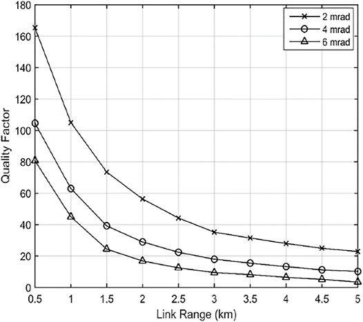
FIGURE 6. Quality Factor vs. Link Range for different beam divergence scenarios.
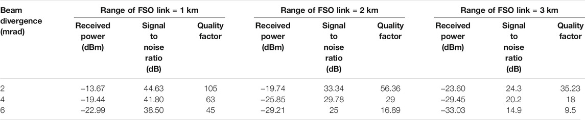
TABLE 2. Analysis of performance characteristics of designed FSO system for different beam divergence scenarios.
Figure 7 illustrates the bit error rate (BER) performance of the designed FSO system for different beam divergence profiles. It has been noticed that the BER performance of the FSO system degrades as the transmission distance of the link is increased. In addition to this, the BER performance gets deteriorated as the beam divergence is increased from 2 to 6 mrad. The maximum achievable link range of the designed system for a reference BER of 10–9 is 8 km. On the contrary, the maximum deliverable link range of the FSO system reduces as the beam divergence increases. Consequently, the maximum achievable link distance of FSO, for a reference BER of 10–9, is 6.6 and 4.5 km for beam divergence of 4 and 6 mrad, respectively. Hence, the maximum possible link range of the FSO system can be controlled by the variation in the FSO beam divergence. For longer operating ranges of the FSO link, the higher beam divergence of the FSO signal imposes a performance constraint on the FSO system. As the operating range of the FSO system is a very crucial factor, utmost care should be taken for controlling beam divergence of the optical beam while configuring the FSO system for a particular link range. Table 3 represents the maximum attainable link distance of the FSO system for different beam divergence profiles.
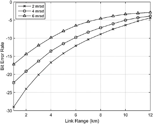
FIGURE 7. Bit Error Rate vs. Link Range for different beam divergence scenarios.

TABLE 3. Maximum achievable link ranges of designed FSO system for different beam divergence scenarios.
The eye diagrams of the designed FSO system transmitting at a range of 3 km have been depicted in Figure 8 for beam divergence of 2 mrad, 4 and 6 mrad. An eye diagram is a measure of intersymbol interference between the bits of the signal. The shape of the eye diagram is purely rectangular in case of ideal transmission and has a maximum opening. On the other hand, its shape gets distorted due to channel impairments and leads to erroneous interpretation of information signals. As depicted in Figure 8A, the eye diagram has a maximum opening indicating less deterioration of data signal due to the small beam divergence of 2 mrad. But as the beam divergence is increased to 4 and 6 mrad, the eye diagrams in Figures 8B,C have demonstrated the degradation of the information signal and the eye height has also been reduced due to higher divergence of the optical beam.
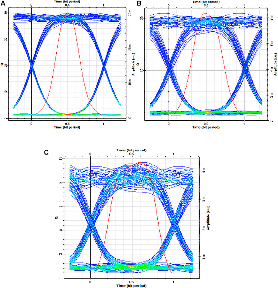
FIGURE 8. Eye diagrams of designed FSO system at a link range of 3 km for beam divergence of (A) 2 mrad (B) 4 mrad (C) 6 mrad.
Table 4 illustrates the comparison of the proposed system design with previous works. The proposed system, which is based on practical and commercial link parameters, has delivered promising results for different beam divergence profiles. The FSO link investigated here operates at a nominal power level of 10 dBm, ensuring the safety of humans working around in the vicinity of the installed link. Moreover, considering market available hardware used in FSO link installation necessitates a reasonable balance between transmission power and available bandwidth as both of these parameters share inverse relation with each other. Therefore, high transmission power may although help in mitigating attenuation and divergence losses, but it also limits the overall transmission capacity of the link. In such a situation the 10 Gbps data rate of the proposed link is not only practically viable but also sufficient enough to suit the needs of last-mile connectivity. Furthermore, the beam divergence of the proposed design is of the order of 6 mrad which is very closely related to divergence conditions which a commercial FSO link reported in [20, 32]. Our investigations have also revealed that in comparison to peer literature considered here, the proposed link is capable of delivering a very descent link range, sufficient enough for last-mile connectivity.
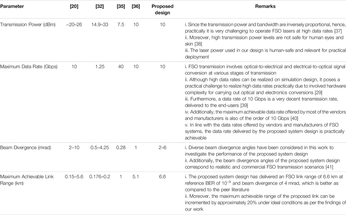
TABLE 4. Comparison of proposed system design with previous work.
Conclusion
We have designed an FSO communication system for a typically practical, commercial, and real-life-based application scenario. Furthermore, the performance characteristics of the FSO system have been examined for different profiles of beam divergence, typically used in commercial FSO systems. The transmission power of FSO link has been set to 10 dBm with an operating wavelength of 1552.5 nm. It has been noticed that the performance characteristics of the designed system degrade as the beam divergence increases from 2 to 6 mrad. At the transmission range of 4 km, the received power has fallen from −26.2 dBm (in case of beam divergence of 2 mrad) to −35.6 dBm (in case of beam divergence value of 6 mrad) as the beam divergence is increased from 2 to 6 mrad. In addition to this, it has been observed that the maximum achievable link distance also gets affected by the change in beam divergence. Since there is always a compromise between the maximum achievable link range and beam divergence of the FSO system, the maximum possible link distances of the designed FSO system have been calculated in this study by considering this performance constraint for different beam divergence profiles. The maximum achievable link distances, for a reference bit error rate of 10–9, get reduced from 8 to 4.5 km as the beam divergence is increased from 2 to 6 mrad, respectively. Although the FSO systems operating with small beam divergence have performed well, the performance of systems can degrade severely due to the slightest alignment issues between the transmitter and the receiver in the case of very small beam divergence. Consequently, the FSO systems should be equipped with automatic tracking and pointing mechanism to avoid link failures in such scenarios. Hence, the beam divergence of the FSO systems is a very crucial factor for FSO links and it should be controlled accordingly so that the information signal can be transmitted reliably over the atmospheric channel. The findings of this research study can be used as recommendations during the installation of practical FSO links to predict the performance of the FSO system and estimate the maximum possible range of FSO links for various beam divergence profiles.
Data Availability Statement
The raw data supporting the conclusion of this article will be made available by the authors, without undue reservation.
Author Contributions
HS: Conceptualization, methodology, investigation, visualization, formal analysis, writing-original draft, resources. RM: Investigation, methodology, visualization, supervision. NM: Methodology, resources, supervision. GG: Visualization, investigation, supervision. MM: Investigation, formal analysis, funding acquisition. SA: Visualization, investigation, funding acquisition.
Funding
This research was funded by Taif University Researchers Supporting Project (TURSP) under number (TURSP-2020/73), Taif University, Taif, Saudi Arabia.
Conflict of Interest
The authors declare that the research was conducted in the absence of any commercial or financial relationships that could be construed as a potential conflict of interest.
Publisher’s Note
All claims expressed in this article are solely those of the authors and do not necessarily represent those of their affiliated organizations, or those of the publisher, the editors and the reviewers. Any product that may be evaluated in this article, or claim that may be made by its manufacturer, is not guaranteed or endorsed by the publisher.
References
1. Morocho-Cayamcela ME, Lee H, Lim W. Machine Learning for 5G/B5G Mobile and Wireless Communications: Potential, Limitations, and Future Directions. IEEE Access (2019) 7:137184–206. doi:10.1109/ACCESS.2019.2942390
2. Esmail MA, Ragheb AM, Fathallah HA, Altamimi M, Alshebeili SA. 5G-28 GHz Signal Transmission over Hybrid All-Optical FSO/RF Link in Dusty Weather Conditions. IEEE Access (2019) 7:24404–10. doi:10.1109/ACCESS.2019.2900000
3. Shafique K, Khawaja BA, Sabir F, Qazi S, Mustaqim M. Internet of Things (IoT) for Next-Generation Smart Systems: A Review of Current Challenges, Future Trends and Prospects for Emerging 5G-IoT Scenarios. IEEE Access (2020) 8:23022–40. doi:10.1109/ACCESS.2020.2970118
4. Masud M, Gaba GS, Choudhary K, Hossain MS, Alhamid MF, Muhammad G. Lightweight and Anonymity-Preserving User Authentication Scheme for IoT-Based Healthcare. IEEE Internet Things J (2021) 1. doi:10.1109/JIOT.2021.3080461
5. Masud M, Gaba GS, Alqahtani S, Muhammad G, Gupta BB, Kumar P, et al. A Lightweight and Robust Secure Key Establishment Protocol for Internet of Medical Things in COVID-19 Patients Care. IEEE Internet Things J (2021) 8:15694–703. doi:10.1109/JIOT.2020.3047662
6. Masud M, Gaba GS, Choudhary K, Alroobaea R, Hossain MS. A Robust and Lightweight Secure Access Scheme for Cloud Based E-Healthcare Services. Peer-to-peer Netw Appl (2021) 14:3043–57. doi:10.1007/s12083-021-01162-x
7. Ding J, Nemati M, Ranaweera C, Choi J. IoT Connectivity Technologies and Applications: A Survey. IEEE Access (2020) 8:67646–73. doi:10.1109/ACCESS.2020.2985932
8. Masud M, Alazab M, Choudhary K, Gaba GS. 3P-SAKE: Privacy-Preserving and Physically Secured Authenticated Key Establishment Protocol for Wireless Industrial Networks. Computer Commun (2021) 175:82–90. doi:10.1016/j.comcom.2021.04.021
9. Huang L, Liu S, Dai P, Li M, Chang G-K, Shi Y, et al. Unified Performance Analysis of Hybrid FSO/RF System with Diversity Combining. J Lightwave Technol (2020) 38:6788–800. doi:10.1109/JLT.2020.3018125
10. Aveta F, Refai HH, Lopresti PG. Cognitive Multi-Point Free Space Optical Communication: Real-Time Users Discovery Using Unsupervised Machine Learning. IEEE Access (2020) 8:207575–88. doi:10.1109/ACCESS.2020.3038624
11. Kashif H, Khan MN, Altalbe A. Hybrid Optical-Radio Transmission System Link Quality: Link Budget Analysis. IEEE Access (2020) 8:65983–92. doi:10.1109/ACCESS.2020.2981661
12. Chaleshtory ZN, Gholami A, Ghassemlooy Z, Sedghi M. Experimental Investigation of Environment Effects on the FSO Link with Turbulence. IEEE Photon Technol Lett (2017) 29:1435–8. doi:10.1109/LPT.2017.2723569
13. Hong Y-Q, Kwon D-H, Choi J-Y, Ha I-H, Shin W-H, Han S-K. SOA-based Multilevel Polarization Shift On-Off Keying Transmission for Free-Space Optical Communication. Photonics (2021) 8:100–8. doi:10.3390/photonics8040100
14. Guiomar FP, Lorences-Riesgo A, Ranzal D, Rocco F, Sousa AN, Fernandes MA, et al. Adaptive Probabilistic Shaped Modulation for High-Capacity Free-Space Optical Links. J Lightwave Technol (2020) 38:6529–41. doi:10.1109/JLT.2020.3012737
15. Kaushal H, Jain VK, Kar S. Free Space Optical Communication. 1st ed. New Delhi, India: Springer (2017). doi:10.1007/978-81-322-3691-7
16. Chauhan S, Miglani R, Kansal L, Gaba GS, Masud M. Performance Analysis and Enhancement of Free Space Optical Links for Developing State-Of-The-Art Smart City Framework. Photonics (2020) 7:132. doi:10.3390/photonics7040132
17. Kaushal H, Kaddoum G. Optical Communication in Space: Challenges and Mitigation Techniques. IEEE Commun Surv Tutorials (2017) 19:57–96. doi:10.1109/COMST.2016.2603518
18. Anbarasi K, Hemanth C, Sangeetha RG. A Review on Channel Models in Free Space Optical Communication Systems. Opt Laser Technology (2017) 97:161–71. doi:10.1016/j.optlastec.2017.06.018
19. Bloom S, Korevaar E, Schuster J, Willebrand H. Understanding the Performance of Free-Space Optics [Invited]. J Opt Netw (2003) 2:178–200. doi:10.1364/JON.2.000178
20. Garlinska M, Pregowska A, Masztalerz K, Osial M. From Mirrors to Free-Space Optical Communication-Historical Aspects in Data Transmission. Future Internet (2020) 12:179–18. doi:10.3390/fi12110179
21. Mansour A, Mesleh R, Abaza M. New Challenges in Wireless and Free Space Optical Communications. Opt Lasers Eng (2017) 89:95–108. doi:10.1016/j.optlaseng.2016.03.027
22. Alkholidi A, Altowij K, Das N. Effect of Clear Atmospheric Turbulence on Quality of Free Space Optical Communications in Western Asia. In: Optical Communications Systems. 1st ed. Rijeka, Croatia: Intech (2012). doi:10.5772/35186
23. Al-gailani SA, Mohd Salleh MF, Salem AA, Shaddad RQ, Sheikh UU, Algeelani NA, et al. A Survey of Free Space Optics (FSO) Communication Systems, Links, and Networks. IEEE Access (2021) 9:7353–73. doi:10.1109/ACCESS.2020.3048049
24. Ghassemlooy Z, Arnon S, Uysal M, Xu Z, Cheng J. Emerging Optical Wireless Communications-Advances and Challenges. IEEE J Select Areas Commun (2015) 33:1738–49. doi:10.1109/JSAC.2015.2458511
25. Son IK, Mao S. A Survey of Free Space Optical Networks. Digital Commun Networks (2017) 3:67–77. doi:10.1016/j.dcan.2016.11.002
26. Chowdhury MZ, Hossan MT, Islam A, Jang YM. A Comparative Survey of Optical Wireless Technologies: Architectures and Applications. IEEE Access (2018) 6:9819–40. doi:10.1109/ACCESS.2018.2792419
27. Leitgeb E, Gebhart M, Birnbacher U, Sheikh Muhammad S, Chlestil C. Applications of Free Space Optics for Broadband Access. In: Proceedings of the Optical Networks & Technologies Conference; 18-20 October 2004; Pisa, Italy. Springer (2005). p. 579–86. doi:10.1007/0-387-23178-1_75
28. Trichili A, Cox MA, Ooi BS, Alouini M-S. Roadmap to Free Space Optics. J Opt Soc Am B (2020) 37:A184–201. doi:10.1364/JOSAB.399168
29. Khalighi MA, Uysal M. Survey on Free Space Optical Communication: A Communication Theory Perspective. IEEE Commun Surv Tutorials (2014) 16:2231–58. doi:10.1109/COMST.2014.2329501
30. Andrews LC, Phillips RL. Laser Beam Propagation through Random Media. 2nd ed. Bellingham, Washington: SPIE Press (2005). doi:10.1117/3.626196
31. Prokes A. Atmospheric Effects on Availability of Free Space Optics Systems. Opt Eng (2009) 48:066001–10. doi:10.1117/1.3155431
33. Mikołajczyk J, Bielecki Z, Bugajski M, Piotrowski J, Wojtas J, Gawron W, et al. Analysis of Free-Space Optics Development. Metrol Meas Syst (2017) 24:653–74. doi:10.1515/mms-2017-0060
34. Liang P, Zhang C, Nebhen J, Chaudhary S, Tang X. Cost-Efficient Hybrid WDM-MDM-Ro-FSO System for Broadband Services in Hospitals. Front Phys (2021) 9:1–7. doi:10.3389/fphy.2021.732236
35. Yeh C-H, Guo B-S, Chang Y-J, Chow C-W, Gu C-S. Bidirectional Free Space Optical Communication (FSO) in WDM Access Network with 1000-m Supportable Free Space Link. Opt Commun (2019) 435:394–8. doi:10.1016/j.optcom.2018.11.060
36. Yaseen MA, Abass AK, Abdulsatar SM. Enhancing of Multiwavelength Free Space Optical Communication System via Optimizing the Transceiver Design Parameters. Opt Quant Electron (2020) 52:1–20. doi:10.1007/s11082-020-02498-z
37. Miglani R, Malhotra JS, Majumdar AK, Tubbal F, Raad R. Multi-Hop Relay Based Free Space Optical Communication Link for Delivering Medical Services in Remote Areas. IEEE Photon J. (2020) 12:1–21. doi:10.1109/JPHOT.2020.3013525
38. O'Brien DC, Katz M. Optical Wireless Communications within Fourth-Generation Wireless Systems [Invited]. J Opt Netw (2005) 4:312–22. doi:10.1364/JON.4.000312
39. Ghassemlooy Z, Popoola W, Rajbhandari S. Optical Wireless Communication: System and Channel Modelling with Matlab. 2nd ed. Boca Raton, FL, USA: CRC Press (2019). doi:10.1201/9781315151724
40. SONAbeam E. SONAbeam (2021). Available at: http://www.fsona.com/prod/SONAbeam_E_Plus.pdf (Accessed November 1, 2021).
Keywords: BER (bit error rate), SNR (signal noise ratio), link range, beam divergence, commercial FSO system, received power
Citation: Singh H, Miglani R, Mittal N, Gaba GS, Masud M and Aljahdali S (2021) Design and Analysis of Commercially Viable Free-Space Optical Communication Link for Diverse Beam Divergence Profiles. Front. Phys. 9:778734. doi: 10.3389/fphy.2021.778734
Received: 17 September 2021; Accepted: 22 November 2021;
Published: 10 December 2021.
Edited by:
Leontios Stampoulidis, Leo Space Photonics R&D, GreeceReviewed by:
Tongyi Zhang, Xian Institute of Optics and Precision Mechanics (CAS), ChinaHaozhe Wang, Massachusetts Institute of Technology, United States
Copyright © 2021 Singh, Miglani, Mittal, Gaba, Masud and Aljahdali. This is an open-access article distributed under the terms of the Creative Commons Attribution License (CC BY). The use, distribution or reproduction in other forums is permitted, provided the original author(s) and the copyright owner(s) are credited and that the original publication in this journal is cited, in accordance with accepted academic practice. No use, distribution or reproduction is permitted which does not comply with these terms.
*Correspondence: Rajan Miglani, rajanmiglani1028@gmail.com