Fatigue Life Assessment Method for Prestressed Concrete Sleepers
 Ruilin You
 Dan Li
 Chayut Ngamkhanong
 Rims Janeliukstis3
- 1Railway Engineering Institute, China Academy of Railway Sciences, Beijing, China
- 2Birmingham Centre for Railway Research and Education, School of Civil Engineering, The University of Birmingham, Edgbaston, United Kingdom
- 3Department of Civil Engineering, Riga Technical University, Riga, Latvia
- 4Department of Civil Engineering, School of Engineering, The University of Birmingham, Birmingham, United Kingdom
Concrete sleepers are one of the most important applications of a railway track system. Researchers have previously studied the impact load characteristics and ultimate load carrying capacity of a prestressed sleeper, but research on the fatigue life of prestressed concrete sleepers is limited. Fatigue damage of a prestressed concrete sleeper is mainly due to the accumulation of defects caused by the repeated load of wheel–rail interaction. Fatigue load, fatigue characteristics, and the existing design methods of prestressed concrete sleeper are summarized in this paper. The commonly used fatigue assessment methods of concrete structures are also evaluated. Based on the results of former research, this article presents a convenient fatigue life assessment method for a prestressed concrete sleeper and contrasts with the test results. The insight information gained can be used to evaluate the service performance and predict the fatigue life of the concrete sleeper, as well providing design flexibility and broadening the design principle. The outcome of this study may also improve the rail track maintenance and inspection criteria, in order to establish an appropriate track condition monitoring network in practice.
Introduction
The railway sleeper is a vital railway component that lies between the rail and the ballast (Zhao et al., 2007). The important functions of sleepers include the following: uniform transfer and distribution of loads from the rail foot to ballast bed, provision of an anchorage for the fastening system, and the restraining of lateral, longitudinal, and vertical movement of the rails (Kaewunruen, 2007; Kaewunruen et al., 2017). The sleepers can be manufactured using timber, concrete, steel, or other engineering materials (Esveld, 2001; Remennikov et al., 2011), and concrete is commonly used around the world.
Since railways play an increasingly important role in the transport system, the demand for sleepers has been increasing over time. The International Federation for Structural Concrete (2006) conducted a worldwide survey of annual demands for different types of sleepers in rail networks and the results are presented in Table 1 (Ferdous and Manalo, 2014).
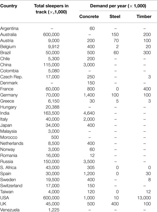
Table 1. Sleepers in rail networks (Ferdous and Manalo, 2014).
Table 1 illustrates that concrete is the dominant material for sleepers worldwide. It makes up more than 50% of the total demand for sleepers. Long service life, flexible sharp design, and being simple to manufacture are the specific advantages of concrete sleepers (Sadeghi and Babaee, 2006; Kaewunruen et al., 2016). A typical railway laying concrete sleeper is shown in Figure 1.
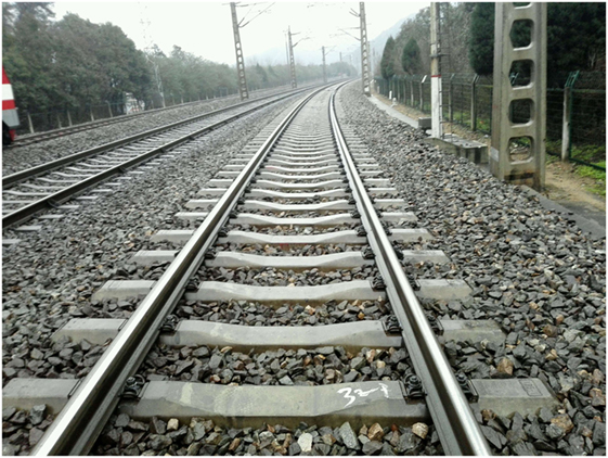
Figure 1. Railway with concrete sleepers.
At present, the permissible stress (or allowable stress) method is adopted in many countries in the manufacturing of concrete sleeper design (AS1085.14, 2003; American Railway Engineering and Maintenance-of-Way Association, 2012). This method relies on the permissible stress of materials and uses a load factor to increase the static axle load to consider dynamic effects (Kaewunruen et al., 2012). Since the permissible stress method does not take into account the dynamic load accurately, while also underestimating the strength of the material, much research has been performed to develop the limit states design approach for concrete sleeper (Wang, 1996; Wakui and Okuda, 1997; Gustavson, 2002). The concept of the limit states design is based on a probabilistic model of the resistance and loads factors and it takes into account a reliable distribution statistic of loads and resistance (Remennikov et al., 2011).
To determine the ability to hold the geometry of a railway line, most railway organizations use a criterion to judge whether the sleeper is valid or not. Therefore, any cracking that leads to a sleeper’s inability to keep the geometry of a railway line has to be considered as failing this criterion. The states of a concrete sleeper can be divided into the following limit states (Leong, 2007; Kaewunruen et al., 2012, 2014).
Ultimate Limit State
The ultimate limit state is caused by a single one-off event, such as a severe wheel flat or derailment accident, which generates an extremely high load, capable of causing the concrete sleeper to fail. This severe event can cause severe cracking at the railseat or at the midspan, and a failure from this event would fit with the ultimate limit state failure definition.
Fatigue Limit State
Fatigue limit state is a time-dependent limit state where a single concrete sleeper accumulates damage progressively over years until it reaches a critical state, where it is considered to have reached failure. Such failures could come from progressive damage (such as abrasion or cracking) from repeated wheel–rail interaction forces over its lifetime.
Serviceability Limit State
Serviceability limit state is a limit state where concrete sleepers are beginning to impose some restrictions or tolerances on the operational capacity of the track, such as sleeper deformations, track stiffness changing, and rail displacement. The serviceability limit state failure of a single sleeper is rarely, if ever, a cause of a speed restriction or a line closure. However, when a cluster of sleepers fail, an operational restriction is usually applied until the problem is rectified.
In the past, a lot of countries have investigated concrete sleepers using numerical models, field studies, and experimental test methods. Researchers from Australia, Canada, Japan, and Sweden have also carried out numerical and experimental studies into the responses of prestressed concrete sleepers under impact load, in order to develop the limit states design approach (Wang, 1996; Wakui and Okuda, 1997; Kaewunruen, 2007). Fatigue properties of materials, such as concrete, reinforced steel, and prestressed steel, under fatigue loading are well established (Hanson et al., 1974; CEB-FIP, 1988; American Association of State Highway and Transportation Officials, 1989; CEB-FIP M 90, 1993; EC2, 2005; AS3600, 2009; Japan Society of Civil Engineers, 2010). A lot of fatigue characteristics of railway bridges are also studied (Li et al., 2001; Olsson and Pettersson, 2010). Recently, some fatigue experiment tests of concrete sleepers have been done (Koh et al., 2016; Parvez and Foster, 2017). However, there was relatively little work carried out on fatigue life assessment of prestressed concrete sleepers.
The main objectives of this paper are to review the reporting on the main characteristics of fatigue failure and fatigue load of prestressed concrete and present the fatigue resistance of prestressed concrete. Then, this article will provide a method to evaluate the service performance and predict the fatigue life of the concrete sleeper, which will be useful for the concrete sleeper design and the rail track maintenance in practice.
Fatigue Failure in Concrete Sleepers
Fatigue failure can be defined as a failure that occurs below the stress limit of a material when it has been exposed to repeated loadings (Thun, 2006). The effects of fatigue are based on the following considerations (Grubb et al., 2007):
• The magnitude of the stress range;
• The type and quality of the structural details;
• The number of applications (or cycles) of this stress range.
The fatigue phenomenon was first observed in steel constructions. In 1830, Albert performed fatigue tests on welded mine hoist chains. The research work concerning fatigue of concrete and concrete structures started at about the turn of the 19th century. After this, much work concerning fatigue in concrete structures has been performed in many countries (Gylltoft, 1983).
The most common problems related to concrete sleepers in North America and worldwide are 94 surveyed and ranked in Table 2 (Stuart, 2013; Ferdous and Manalo, 2014).
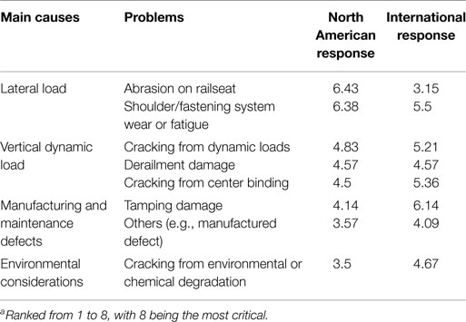
Table 2. Critical problems related to concrete sleepersa (Stuart, 2013; Ferdous and Manalo, 2014).
From Figure 2, we can see that deterioration, abrasion, and cracking are the main problems related to concrete sleepers (Murray and Cai, 1998). While abrasion and chemical degradation are not pure structural actions, cracking is considered ordinarily as the failure criterion to define fatigue state for concrete sleepers in design process. The main types of crack of concrete sleepers are shown in Figures 2–4.
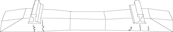
Figure 2. Cracks near the railseat.
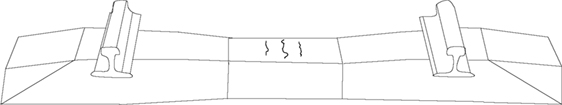
Figure 3. Cracks at the center of the sleeper.
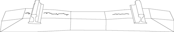
Figure 4. Longitudinal cracks of the sleeper.
Fatigue Load and Current Design Methodologies
For concrete sleepers, cracking may develop due to excessive flexural, shear, or bond stresses (Hawkins and Shah, 1982). However, the progression of cracking depends on the fatigue load and the resistance of the material. The fatigue load of a concrete sleeper is the wheel–rail interaction force, which can be divided into dynamic load and impact load (Van Dyk et al., 2017). The dynamic load is the additional load due to the effects of normal wheel–rail interactions. The impact load is created by the track and vehicles through wheel or track’s irregularities (Kaewunruen and Remennikov, 2009b, 2013; Van Dyk et al., 2017).
Dynamic Load
It is well know that dynamic load is used commonly in the design process of railway tracks and railway applications. The dynamic load considers the dynamic wheel–rail interaction in normal situations; it does not include the extreme impact factor (IF) in railways. Dynamic load is usually related to the train speed and is used for the permissible stress design method. The dynamic wheel load is generally expressed as a function of the static wheel load (Eq. 1) (Doyle, 1980):
where Pd is the dynamic wheel load, ∅ is the dynamic wheel load factor (∅ > 1), and Ps is the static wheel load.
Railway engineers around the world have recommended several formulas and parameters for calculating the dynamic wheel load factor. Based on field data, the expression used for the calculation of the dynamic factor ∅ is typically developed empirically and is always expressed in terms of train speed (Doyle, 1980; Van Dyk et al., 2017).
Talbot (1953), Clarke (1957), and the South African Railways (1974) proposed an equation to calculate the dynamic factor that incorporates train speed and the wheel diameter (Doyle, 1980; Hay, 1982). Indian Railways (1974) proposed the dynamic factor by incorporating train speed and track modulus (Srinivasan, 1969). Eisenmann (1972) used a statistical approach to propose a dynamic factor that incorporates train speed and the condition of the track (Esveld, 2001). UIC (1965) developed the most comprehensive dynamic factor, which incorporates the train speed, track geometry, track age, curve radius, superelevation, cant deficiency, vehicle suspension, and center of gravity of the vehicle (Birmann, 1965). The Deutsche Bahn (Germany Railways, 1943) began using an equation (when the train speed is no more than 200 km/h) to calculate the dynamic factor only using train speed (Schramm, 1961). British Railways developed a dynamic factor in the 1970s, which related to a vehicle’s unsprung mass, track stiffness, and train speed (Doyle, 1980). In 1968, the Washington Metropolitan Area Transit Authority prepared an equation where the dynamic factor only depended on the train speed, using subsequent recommended standards for transit track work (Prause et al., 1974). The American Railway Engineering and Maintenance-of-Way Association defines the speed factor for concrete sleeper design in chapter 30. When checking the strength of a railway track in China, the dynamic factor, the speed coefficient, and the wheel load shift coefficient in curves are all taken into account. When calculating the load of sleepers at a railseat, a lateral force coefficient should be also considered (Xiufang Chen, 2017). Table 3 shows a summary of the main recommendations for the dynamic wheel load factor.
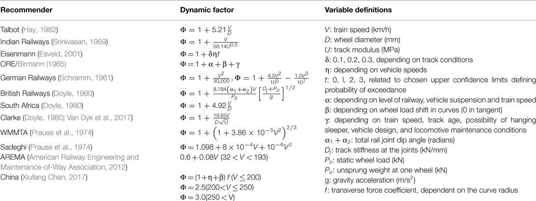
Table 3. Recommended relationship for dynamic coefficient factors (Doyle, 1980; Van Dyk et al., 2017).
With some reasonable assumptions and accordingly simplified parts of the factor, the design dynamic factors, increasing with speed, are displayed in Figure 5 (Doyle, 1980; Van Dyk et al., 2017).
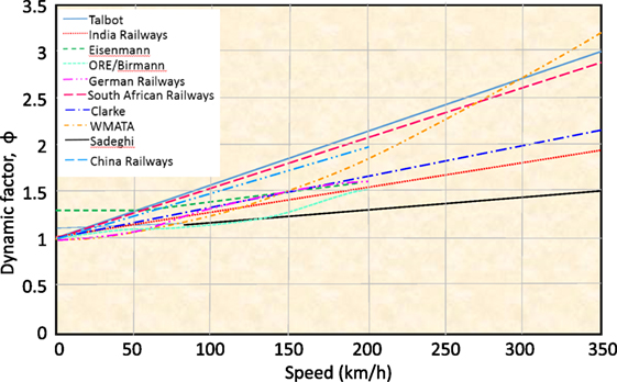
Figure 5. Design dynamic factors increasing due to speed (Doyle, 1980; Van Dyk et al., 2017).
Brandon J. Van and J. Riley Edwards used field test data on Amtrak’s Northeast Corridor to evaluate the dynamic factor (Van Dyk et al., 2017). After removing the abnormal data or some recoded in error, the relationship between the dynamic factors and the train speeds is evaluated as follows (Van Dyk et al., 2017):
Impact Load
It is not unusual that railway tracks suffer from impact loads, which are caused by the wheel–rail interactions associated with the abnormalities in the wheels or rails (Kaewunruen and Remennikov, 2006, 2009a,b, 2007) The magnitude of the impact loads on the railseat of concrete sleepers greatly exceeds the static wheel load. The value of the impact load is not only related to the train speed, but is also dependent on causes of such loads (e.g., wheel flats, out-of round wheels, wheel corrugation, short and long wavelength rail corrugation, dipped welds and joints, pitting, and shelling) (Kaewunruen and Remennikov, 2013). It should be noted that impact capacity of concrete sleepers on the railseat can be reduced due to the modification for add-on fixture in practice and surface abrasions (Ngamkhanong et al., 2017a,b,c,d).
Wakui and Okuda (1997) measured the axle-box acceleration of a wheel-set axle-box to study the characteristics of impact loads. They found that the impact load can be simplified as a shock pulse acting after the static wheel load is removed; the duration of impact wheel loading ranges widely from 1 to 10 ms.
Brandon J. Van Dyk and J. Riley Edwards used the wheel impact load detector (WILD) data to evaluate the IF of the North American railway (Van Dyk et al., 2017). The sites of WILD are typically constructed on well-maintained tangent railway track structures with concrete sleepers. The actual wheel loading at Union Pacific Rail Road’s Gothenburg, Nebraska, shows that the IF is related to the axle load of the train. Moreover, part of the impact of the wheel load is very large and even exceeds the static wheel load five times (Table 4).
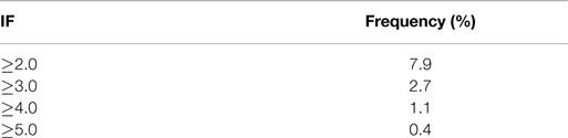
Table 4. The probability of different impact factors (IFs) from statistical data (Van Dyk et al., 2017).
Queensland University of Technology (2004), Australia also did a comprehensive investigation of actual impact loads. Nearly six million passing wheels on different heavy haul mineral lines were measured in the investigation. The static axle load of the test train ranged from 26 to 28 t, including full-load and no-load conditions. Figure 6 shows the statistical result of field test wheel loads obtained from the rail line in North Queensland of Australia (Leong, 2007).
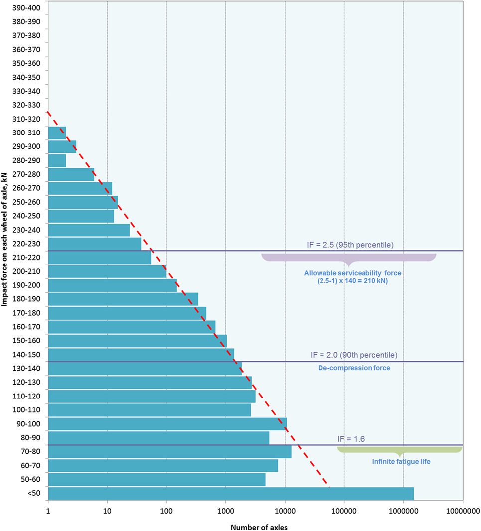
Figure 6. Typical impact force statistical data on track at Braeside (Leong, 2007).
Based on the return periods and consequences of changing operational characteristics and the statistical data, the impact force factor (ki) is calculated for the sites as below:
where R is the return period (years); V, velocity.
The relationships between the return periods (R) and the impact forces I (kN) could be expressed as:
Current Design Methodologies of Concrete Sleepers
In current practice, the structural design process for concrete sleepers consists of the following steps (Grassie, 1984):
• Analysis of dynamic load coefficient;
• Calculating sleeper railseat loads;
• Assuming the support conditions of the sleeper;
• Calculating the bend moment of the critical sections of the sleeper.
Countries or regions with rapid development of railway transportation have promulgated the design method of concrete sleepers for their own railway tracks. American Railway Engineering and Maintenance-of-Way Association (2012), Euro Norm (CEN, 2009), International Union of Railways (UIC, 2004), Australian Standard (AS1085.14, 2003), and Chinese Railway (2015) all provide formal recommendations on the analysis portion of the concrete design process. Table 5 provides a comparison of different analysis methods mentioned above.
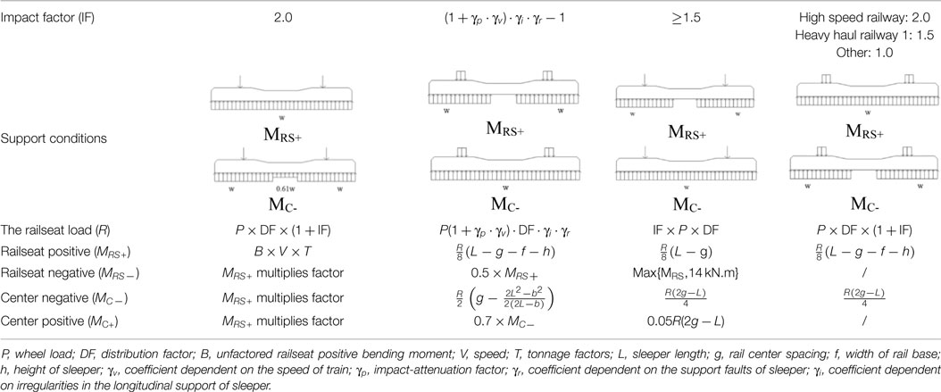
Table 5. Comparison of different analysis methods for concrete sleepers (standard gauge).
Fatigue Properties of Materials
Concrete
Fatigue of concrete is a progressive process of microcrack initiation and propagation toward to the point at which failure occurs. The mechanical properties of concrete will change under repeated cyclic loading, such as permanently increasing strain on the concrete, causing the stiffness to decrease. Cyclic loading may also cause a concentration of stress at the prestressed wires’ surface, which can lead to sudden fracture (Mallet, 1991; Parvez and Foster, 2017).
In the 1970s, a lot of research regarding concrete fatigue analysis was done for the construction of offshore structures in Scandinavia, which suffered severe repeated loads due to the tide Da Mata Bilé and Student1. The fatigue performance of concrete is commonly represented on graphs, with stress ranges plotted against the failure cycles number (Keynia, 1998). To assess fatigue performance, the Goodman diagram has been developed (Figure 7) (Keynia, 1998; Sadeghi and Fathali, 2007). is the allowable compressive stress of concrete, Nf is the number of allowable load cycles, σt is the maximum stress caused by a dead load, and σh is the maximum stress caused by both live and dead loads.
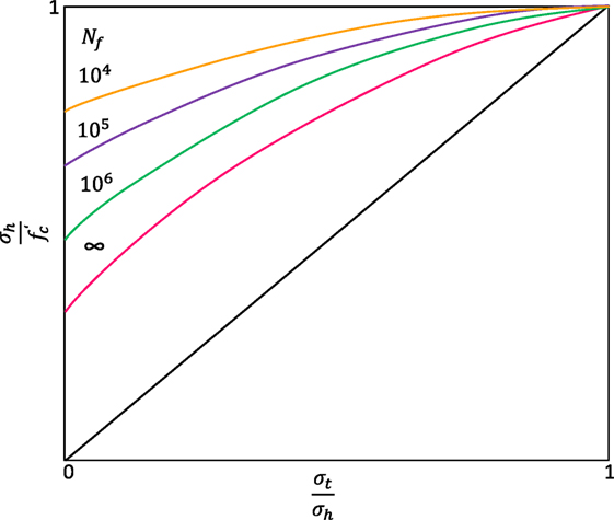
Figure 7. The Goodman diagram.
The fatigue reference compressive strength fck,fat of concrete (fib Model Code 2010) is calculated based on the characteristic compressive strength fck as follows:
In Eq. 5 and is a coefficient which depends on the time under high sustained loads t − t0 (days). The expression of βcc(t) from Eq. 6 describes the strength of the concrete, which is developing with time, in which s depends on the cement strength class and t equals to the age of concrete age (in days) (Lantsoght et al., 2016).
The typical S–N curves of concrete under pure compression are shown in Figure 8. N is the number of cycles causing fatigue failure in plain concrete
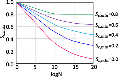
Figure 8. S–N curves for concrete under pure compression (fib Model Code 2010).
Prestressed Steel
In the fib Model Code 2010, the characteristic fatigue strength function for prestressed steel consists of two different slope segments (see Figure 9). The parameters of the prestressed steel’s S–N curve are shown in Table 6. is the stress range obtained from a characteristic fatigue strength function.
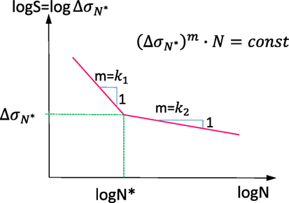
Figure 9. S–N curves for steel (fib Model Code 2010).
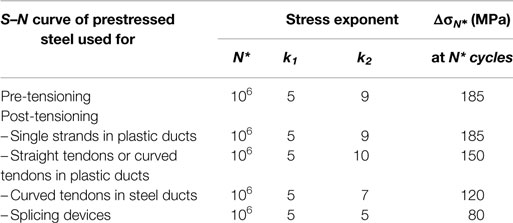
Table 6. Parameters of prestressed steel’s S–N curves (fib Model Code 2010).
Fatigue Assessment Methods
There are two methods commonly used for fatigue verification: the damage accumulation method and the damage equivalent stress method.
The Damage Accumulation Method
Extending Miner’s rule, the damage accumulation method is used in many design codes (BS5400, 1980; EC2, 2005). In this method, the cumulative damage accumulation under variable amplitude loading for a particular sample of stress history is calculated as an equivalent fatigue stress with constant amplitude (Rao and Talukdar, 2003)
In the above equation DI is the cumulative damage index, Dj is the incremental damage, nj is the number of cycles at stress range Srj, Nj is the number of cycles at constant stress range Srj to cause fatigue failure, kb is the stress range number blocks in the histogram over which summation is carried out. The process of evaluating the cumulative damage index has been repeated for all the simulated response samples and the average value is used to find the fatigue life Lf using:
The Damage Equivalent Stress Method
The Damage Equivalent Stress Method, presented in Annex NN of EN 1992-2:2005, is a simplified method compared to the Cumulative Damage Method. This method is used to evaluate the fatigue safety of structures, based on an equivalent fatigue stress with constant amplitude. This assessment method is applicable to reinforced and prestressed steel for road and railway bridges.
The obtained stresses are multiplied by damage equivalent factors, which are dependent on different infected factors. The expression of damage equivalent factor is given as follows:
In the above equation, φfat is the damage equivalent IF, which is dependent on the surface roughness. λs,1 is a factor related to damaging effect of traffic and dependent on the critical length of the influence line or area. λs,2 is a factor that is controlled by the traffic volume. λs,3 is a factor that is dependent on the design life of the bridge. λs,4 is a factor used for bridges that are loaded by more than one lane.
Fatigue Assessment Methods for Concrete Sleeper
All the methods above are commonly used for the fatigue life assessment of bridges. Because of the periodic impact load, the fatigue assessment process for concrete sleepers is different from bridges. At present, there is not a suitable fatigue assessment method for concrete sleepers.
Based on field tests and laboratory test results, Wakui and Okuda (1997) proposed a method for evaluating the fatigue life of a prestressed concrete sleeper, according to a prestressed steel rupture, due to impact load, by using the following procedure:
• Construct a cumulative frequency distribution curve of wheel loading.
• Calculate the sleeper flexural moments by the equations based on test data and engineering experience to get the cumulative frequency curve of loads.
• Evaluate the fatigue life that a prestressed concrete sleeper imposes, resorting to the cumulative frequency distribution curve of prestressed steel stress, the fatigue resistance of the prestressed steel and Miner’s hypothesis.
Kaewunruen and Remennikov (2009a,b) did a lot of research regarding the response of prestressed concrete sleepers under impact loads. By using the concept of damage accumulation, they presented a method for predicting the residual life of concrete sleepers under repeated impact loads, using the relationships between the cumulative damage of sleepers and given impact loads.
Based on laboratory tests, the relationships between the cumulative damage index and the impact loads in different track environments are shown in Figure 10. The damage index in the figure is the ratio between the maximum crack length cmax caused by the bending moment and the total depth (d) of the sleeper. This ratio is used to quantify and classify the damage states of concrete sleepers subjected to impact loads. Based on the test results, the damage index can also be used to predict the residual life of concrete sleepers.
Figure 10. Damage index of concrete sleepers in different track environments.
Case Study: Fatigue Life Assessment for Prestressed Concrete Sleeper
Parvez and Foster (2017) have done some experiments about the fatigue behavior of prestressed concrete sleepers. Based on their test results, this paper will assess the life of the prestressed concrete sleepers subjected to fatigue loading. In the calculation process, the fatigue failure of sleepers is judged by the fracture of the prestressed steel.
Experimental Specimen and Program
The tested concrete sleepers comply with the requirements of AS 1085.14. Each sleeper consisted of 18 prestressed wires with 26.4 kN prestressed force per wire, loss of prestress is calculated as 12%. The geometry details are given in Table 7, and the railseat section can be seen in Figure 11.
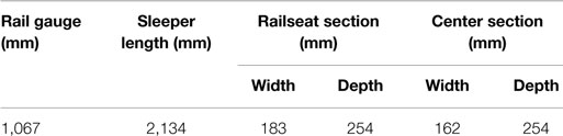
Table 7. Dimensions of the test sleepers (Parvez, 2015; Parvez and Foster, 2017).
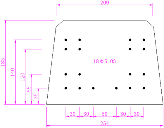
Figure 11. Railseat section of sleeper (millimeter) (Parvez, 2015; Parvez and Foster, 2017).
The fatigue test almost followed the set up that was specified in AS 1085.14 (Figure 12). In order to make sure the sleeper failed below three million cycles, the upper limit of fatigue load was increased to 240 kN (36% higher than specified standard value). The fatigue test load protocol can be seen in Figure 13.
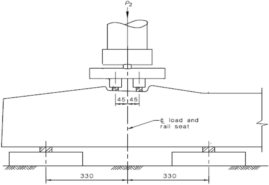
Figure 12. Fatigue test set up (millimeter).
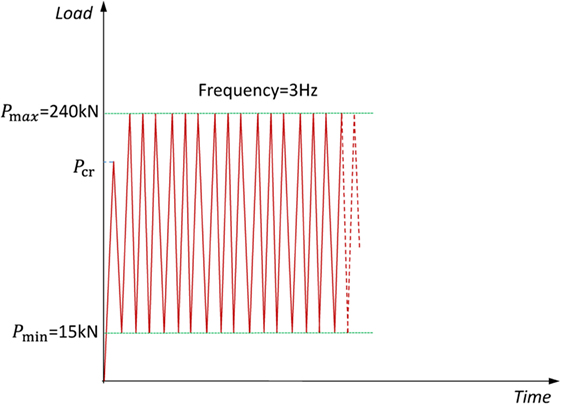
Figure 13. Fatigue test load protocol.
Properties of the materials
The properties of materials can be seen in Table 8.
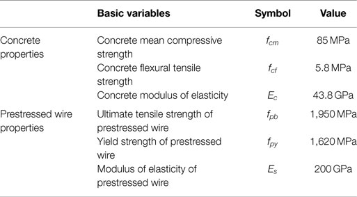
Table 8. Properties of the materials (Parvez, 2015; Parvez and Foster, 2017).
Calculation of Fatigue Life
Cracking Load Calculation
Modulus of elasticity ratio of prestressed wire and concrete ne = Es/Ec = 4.57.
Area of single prestressed wire Aps = 19.9 mm2.
Total area of prestressed wires Ap = ne ⋅ Aps = 357.7 mm2.
Area of concrete section Ac = 42,141.2 mm2.
Distance from the soffit to the center of gravity of the concrete, yc = 88.1 mm.
Distance from the soffit to the center of gravity of the prestressed wires, yp = 83.9 mm.
Transformed area:
First moment about the bottom fiber:
Distance of the centroidal axis of transformed area from the soffit:
Eccentricity of the centroid of prestressed force:
Inertia moment of transformed section:
Initial prestress pre-wire:
Effective prestress pre-wire:
Before cracking, the strains at different levels in the sleeper varied linearly with depth and the concrete stress at the bottom fiber due to the prestress force can be calculated as:
Cracking moment :
Cracking load:
The comparison between the theoretical and experiment results are shown in Table 9.
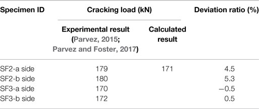
Table 9. Comparison of cracking load.
Calculation of Fatigue Life
With progression in the sleeper’s cracks, the neutral axis of concrete section will change, when the section is fully cracked, the prosperity of the section can be calculated as follows:
• Transform the area of concrete section, AcII;
• Positive first moment about the transformed area, SpcII;
• Trial the center of gravity for the effective transformed concrete section as follows, where ycg is the distance from the center of gravity of the effective transformed area to the top of the section;
Effective moment of inertia:
Where the quantity Ms is the maximum bending moment at the section:
Tension stress range in the first layer prestress wire at the bottom:
The failure cycle of the prestressed steel under constant amplitude cyclic loading is estimated based on fib Model Code 2010 (Figure 10) and is represented by Eqs. 27 and 28:
Where Δσ is the stress range in the prestressed steel, is the stress range at N* cycles, which is given in Table 6. Since the fatigue test data are significantly scattered and are influenced by the sample size and loading frequency, the S–N curve is considered as an engineering factor. The curve in fib Model Code is expected to be a safe assumption. Hence, the parameters given in Table 6 are used for design. The parameters are, however, lower bound to test the data and are appropriately conservative (Loo et al., 2010). For comparison with test results, however, mean values are needed to provide a best estimate of the response. Loo et al. (2010) suggested that the mean value for reinforced steel is 290 MPa, and Parvez and Foster (2015) suggested that the mean value is 300 MPa for the prestressed steel. In this case study, consider as 300 Mpa:
The comparison between the theoretical and experiment results are shown in Table 10.
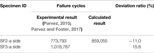
Table 10. Comparison of fatigue life.
Conclusion
Prestressed concrete sleepers are the most common and important component of railway track systems. There are many factors that cause the failure of prestressed concrete sleepers, in which cracking is commonly considered as a failure criterion defining fatigue failure state. The fatigue damage of the prestressed concrete sleepers is mainly due to the cumulative accumulation caused by the fatigue load from trains. In order to evaluate the fatigue lifetime of the prestressed concrete sleepers, the following aspects of work need to be carried out:
• Statistical analysis of fatigue dynamic load, impact load from the train and bending moment of prestressed concrete sleeper;
• Study of the fatigue characteristics of prestressed concrete sleepers (including S–N curves of concrete and steel bars) and their materials;
• Development of reasonable fatigue life discrimination criteria, according to the load moment and material characteristics, to calculate the fatigue life of a prestressed concrete sleeper.
For the detailed prediction of the fatigue life of the prestressed concrete sleeper, a great deal of theoretical analyses, laboratory tests, and field tests are still required. This paper reviewed the reports on the main characteristics of fatigue failure and fatigue load of prestressed concrete, in the presence of the fatigue resistance of prestressed concrete. This article also presents a convenient fatigue life assessment method for prestressed concrete sleepers. The outcome of this study can be used to evaluate the service performance and predict the fatigue life of concrete sleepers, as well as to help to engineer and improve concrete sleeper design and maintenance.
Author Contributions
RY wrote the manuscript with support from other authors, and developed the theoretical formalism, performed the analytic calculations. SK gave very useful comments on this manuscript. DL makes a contribution to the information for the fatigue failure in concrete sleepers. CN made a contribution to review current design methodologies. RJ made a contribution to the fatigue life assessment case study.
Conflict of Interest Statement
The authors declare that the research was conducted in the absence of any commercial or financial relationships that could be construed as a potential conflict of interest.
Acknowledgments
The first author wishes to thank China Academy of Railway Sciences (CARS) for financial sponsorship of the collaborative project at the University of Birmingham (UoB). The first author also wishes to gratefully acknowledge the help from the Birmingham Centre for Railway Research and Education (BCRRE) at work in the UoB. All authors send special thanks to the European Commission for H2020-MSCA-RISE, Project No. 691135 “RISEN: Rail Infrastructure Systems Engineering Network”, which enables a global research network that tackles the grand challenge in railway infrastructure resilience (Kaewunruen et al., 2016) and advanced sensing (www.risen2rail.eu).
Footnote
- ^Da Mata Bilé, C. E., and Student, M. Fatigue Assessment in Railway Prestressed Concrete Bridges. Lisboa. Available at: https://fenix.tecnico.ulisboa.pt/downloadFile/395145010485/artigo_55003.pdf (accessed in 2017).
References
American Association of State Highway and Transportation Officials. (1989). Guide Specifications for Fatigue of Steel Bridges. Washington, DC: American Association of State Highway and Transportation Officials.
American Railway Engineering and Maintenance-of-Way Association. (2012). AREMA-Manual for Railway Engineering, Chap. 30. USA: American Railway Engineering and Maintenance-of-Way Association.
AS1085.14. (2003). AS1085.14-2003 Railway Track Material – Part 14: Prestressed Concrete Sleepers. Australia: Standards Australia.
AS3600. (2009). Australian Standard. AS3600 Design of Concrete Structures. Australia: Standards Australia.
Birmann, F. (1965). Paper 5: Track Parameters, Static and Dynamic, Proceedings of the Institution of Mechanical Engineers, Conference Proceedings. London, UK: SAGE, 73–85.
BS5400. (1980). BS5400 Steel, Concrete and Composite Bridges, Part 10: Code of Practice for Fatigue. United Kingdom: British Standards Institution.
CEB-FIP. (1988). Fatigue of Concrete Structures: State of the Art Report. Dubrovnik: Bulletin D’information, du Béton, No 188.
CEB-FIP M 90. (1993). Design of Concrete Structures. CEB-FIP Model Code 1990. London: British Standard Institution.
CEN. (2009). 13230-1, Railway Applications-Track-Concrete Sleepers and Bearers-Part 1: General Requirements. London: British Standard.
Chinese Railway. (2015). Q/CR 9130-2015-Provisional Code for Limit State Design Method of Railway Track. China: Chinese Railway.
Doyle, N. F. (1980). Railway Track Design: A Review of Current Practice. Occasional Paper, No. 35. Canberra: Bureau of Transport Economics, Commonwealth of Australia.
EC2. (2005). Design of Concrete Structures—Part 2: Concrete Bridges Design and Detailing Rules. United Kingdom: British Standard.
Ferdous, W., and Manalo, A. (2014). Failures of mainline railway sleepers and suggested remedies – review of current practice. Eng. Fail. Anal. 44, 17–35. doi: 10.1016/j.engfailanal.2014.04.020
Grassie, S. L. (1984). Dynamic Modelling of Railway Track and Wheelsets. UK: Department of Engineering, University of Cambridge.
Grubb, M. A., Corven, J. A., Wilson, K. E., Bouscher, J. W., and Volle, L. E. (2007). Load and Resistance Factor Design (LRFD) For Highway Bridge Superstructures-Design Manual. Washington, DC: Federal Highway Administration.
Gustavson, R. (2002). Structural Behaviour of Concrete Railway Sleepers. Göteborg: Chalmers University of Technology.
Gylltoft, K. (1983). Fracture Mechanics Models for Fatigue in Concrete Structures. Luleå: Luleå Tekniska Universitet.
Hanson, J. M., Ballinger, C. A., and Linger, D. (1974). Considerations for design of concrete structures subjected to fatigue loading. ACI J. 71, 97–120.
Hawkins, N., and Shah, S. (1982). American Concrete Institute Considerations for Fatigue. ZÜrich: International Association for Bridge and Structural Engineering, 41–50.
Japan Society of Civil Engineers. (2010). Standard Specifications for Concrete Structures-2007 “Design”. Japan: Japan Society of Civil Engineers.
Kaewunruen, S. (2007). Experimental and Numerical Studies for Evaluating Dynamic Behaviour of Prestressed Concrete Sleepers Subject to Severe Impact Loading. Wollongong: University of Wollongong.
Kaewunruen, S., Gamage, E. K., and Remennikov, A. M. (2016). Structural behaviours of railway prestressed concrete sleepers (crossties) with hole and web openings. Proc. Eng. 161, 1247–1253.
Kaewunruen, S., and Remennikov, A. (2007). Experimental and Numerical Studies of Railway Prestressed Concrete Sleepers under Static and Impact Loads. Civil Computing. 3, 25–28.
Kaewunruen, S., and Remennikov, A. (2013). On the residual energy toughness of prestressed concrete sleepers in railway track structures subjected to repeated impact loads. Electron. J. Struct. Eng. 13, 41–61.
Kaewunruen, S., Remennikov, A., and Murray, M. H. (2012). Limit states design of railway concrete sleepers. Proc. Inst. Civil Eng. Trans. 165, 81–85.
Kaewunruen, S., and Remennikov, A. M. (2006). Sensitivity analysis of free vibration characteristics of an in situ railway concrete sleeper to variations of rail pad parameters. J. Sound Vib. 298, 453–461. doi:10.1016/j.jsv.2006.05.034
Kaewunruen, S., and Remennikov, A. M. (2009a). Impact capacity of railway prestressed concrete sleepers. Eng. Fail. Anal. 16, 1520–1532. doi:10.1016/j.engfailanal.2008.09.026
Kaewunruen, S., and Remennikov, A. M. (2009b). Progressive failure of prestressed concrete sleepers under multiple high-intensity impact loads. Eng. Struct. 31, 2460–2473. doi:10.1016/j.engstruct.2009.06.002
Kaewunruen, S., Remennikov, A. M., and Murray, M. H. (2014). Introducing a new limit states design concept to railway concrete sleepers: an Australian experience. Front. Mater. 1:8. doi:10.3389/fmats.2014.00008
Kaewunruen, S., You, R., and Ishida, M. (2017). Composites for timber-replacement bearers in railway switches and crossings. Infrastructures 2, 13. doi:10.3390/infrastructures2040013
Keynia, A. M. (1998). Structural Analysis of Reinforced Concrete. Iran: Isfahan University of Technology Press.
Koh, T., Shin, M., Bae, Y., and Hwang, S. (2016). Structural performances of an eco-friendly prestressed concrete sleeper. Constr. Build. Mater. 102, 445–454. doi:10.1016/j.conbuildmat.2015.10.189
Lantsoght, E. O., van der Veen, C., and de Boer, A. (2016). Proposal for the fatigue strength of concrete under cycles of compression. Constr. Build. Mater. 107, 138–156. doi:10.1016/j.conbuildmat.2016.01.007
Leong, J. (2007). Development of a Limit State Design Methodology for Railway Track. Brisbane: Queensland University of Technology.
Li, Z., Chan, T. H., and Ko, J. M. (2001). Fatigue analysis and life prediction of bridges with structural health monitoring data—part I: methodology and strategy. Int. J. Fatigue 23, 45–53. doi:10.1016/S0142-1123(00)00068-2
Loo, K. Y. M., Foster, S., and Smith, S. (2010). Fatigue Behaviour of CFRP-Repaired Corroded RC Beams. Ph.D. thesis, School of Civil and Environmental Engineering, The University of New South Wales, Sydney, Australia.
Mallet, G. P. (1991). Fatigue of Reinforced Concrete, State of the Art Review/2, Transport and Road Research Laboratory. London: HMSO, 8.
Murray, M., and Cai, Z. (1998). Literature Review on the Design of Railway Prestressed Concrete Sleeper. Australia: RSTA research report.
Ngamkhanong, C., Li, D., and Kaewunruen, S. (2017a). “Impact capacity reduction in railway prestressed concrete sleepers with surface abrasions,” in World Multidisciplinary Civil Engineering – Architecture – Urban Planning Symposium, (Prague, Czech Republic: IOP Publishing Ltd).
Ngamkhanong, C., Li, D., and Kaewunruen, S. (2017b). “Impact capacity reduction in railway prestressed concrete sleepers with vertical holes,” in Building up Efficient and Sustainable Transport Infrastructure 2017 (BESTInfra2017). IOP Conference Series: Materials Science and Engineering, No. 1, vol. 236, (Prague: IOP Publishing).
Ngamkhanong, C., Kaewunruen, S., and Remennikov, A. (2017c). “Static and dynamic behaviours of railway prestressed concrete sleepers with longitudinal through hole,” in 3rd International Conference on Innovative Materials, Structures and Technologies. IOP Conference Series: Materials Science and Engineering, (Riga, Latvia: IOP Publishing).
Ngamkhanong, C., Li, D., Remennikov, A., and Kaewunruen, S. (2017d). “Capacity reduction in railway prestressed concrete sleepers due to dynamic abrasions,” in 15th East-Asia Pacific Conference on Structural Engineering and Construction, (Xi’an, China: Tongji University).
Olsson, K., and Pettersson, J. (2010). Fatigue Assessment Methods for Reinforced Concrete Bridges in Eurocode. Comparative Study of Design Methods for Railway Bridges. Göteborg: Chalmers University of Technology.
Parvez, A. (2015). Fatigue Behaviour of Steel-Fibre-Reinforced Concrete Beams and Prestressed Sleepers. Sydney: The University of New South Wales.
Parvez, A., and Foster, S. J. (2017). Fatigue of steel-fibre-reinforced concrete prestressed railway sleepers. Eng. Struct. 141, 241–250. doi:10.1016/j.engstruct.2017.03.025
Prause, R., Meacham, H., Harrison, H., John, T., and Glaeser, W. (1974). Assessment of Design Tools and Criteria for Urban Rail Track Structures, Vol. 1. Report No. UMTA-MA-06-0025-74-3. Urban Mass Transit Administration.
Rao, V., and Talukdar, S. (2003). Prediction of fatigue life of a continuous bridge girder based on vehicle induced stress history. Shock Vib. 10, 325–338. doi:10.1155/2003/309413
Remennikov, A. M., Murray, M. H., and Kaewunruen, S. (2011). Reliability-based conversion of a structural design code for railway prestressed concrete sleepers. Proc. Inst. Mech. Eng. F 226, 155–173. doi:10.1177/0954409711418754
Sadeghi, J., and Babaee, A. (2006). Structural optimization of B70 railway prestressed concrete sleepers. Iran. J. Sci. Technol. Trans. B Eng. 30, 461–473. doi:10.22099/IJSTC.2013.773
Sadeghi, J., and Fathali, M. (2007). Deterioration analysis of concrete bridges under inadmissible loads from the fatigue point of view. Sci. Iran. 14, 185–192.
Stuart, C. (2013). International Concrete Crosstie and Fastening System Survey. Washington, DC: Research Results.
Thun, H. (2006). Assessment of Fatigue Resistance and Strength in Existing Concrete Structures. Luleå: Luleå Tekniska Universitet.
Van Dyk, B. J., Edwards, J. R., Dersch, M. S., Ruppert, C. J. Jr., and Barkan, C. P. (2017). Evaluation of dynamic and impact wheel load factors and their application in design processes. Proc. Inst. Mech. Eng. F 231, 33–43. doi:10.1177/0954409715619454
Wakui, H., and Okuda, H. (1997). A study on limit state design method for prestressed concrete sleepers. Doboku Gakkai Ronbunshu 1997, 35–54. doi:10.2208/jscej.1997.557_35
Wang, N. (1996). Resistance of Concrete Railroad Ties to Impact Loading. Vancouver: University of British Columbia.
Keywords: railway, fatigue load, prestressed concrete sleeper, fatigue life, assessment method
Citation: You R, Li D, Ngamkhanong C, Janeliukstis R and Kaewunruen S (2017) Fatigue Life Assessment Method for Prestressed Concrete Sleepers. Front. Built Environ. 3:68. doi: 10.3389/fbuil.2017.00068
Received: 03 June 2017; Accepted: 18 October 2017;
Published: 15 November 2017
Edited by:
Hua Chen, Railway Technical Research Institute, JapanReviewed by:
Cheul Kyu Lee, Korea Railroad Research Institute, South KoreaSamer Dessouky, University of Texas at San Antonio, United States
Makoto Ishida, Nippon Koei Co., Ltd., Japan
Copyright: © 2017 You, Li, Ngamkhanong, Janeliukstis and Kaewunruen. This is an open-access article distributed under the terms of the Creative Commons Attribution License (CC BY). The use, distribution or reproduction in other forums is permitted, provided the original author(s) or licensor are credited and that the original publication in this journal is cited, in accordance with accepted academic practice. No use, distribution or reproduction is permitted which does not comply with these terms.
*Correspondence: Ruilin You, youruilin0731@126.com