Electrically conductive polyaniline-coated electrospun poly(vinylidene fluoride) mats
 Claudia Merlini1*
  Guilherme Mariz de Oliveira Barra1*
  Sílvia Daniela Araújo da Silva Ramôa1
 Giseli Contri1
 Rosemeire dos Santos Almeida2
 Marcos Akira d’Ávila2
  Bluma G. Soares3
- 1Department of Mechanical Engineering, Universidade Federal de Santa Catarina, Florianópolis, Brazil
- 2School of Mechanical Engineering, Universidade Estadual de Campinas (UNICAMP), Campinas, Brazil
- 3Instituto de Macromoléculas, Universidade Federal do Rio de Janeiro, Rio de Janeiro, Brazil
Electrically conductive polyaniline (PANI)-coated electrospun poly(vinylidene fluoride) (PVDF) mats were fabricated through aniline (ANI) oxidative polymerization on electrospun PVDF mats. The effect of polymerization condition on structure and property of PVDF/PANI mats was investigated. The electrical conductivity and PANI content enhanced significantly with increasing ANI concentration due to the formation of a conducting polymer layer that completely coated the PVDF fibers surface. The PANI deposition on the PVDF fibers surface increased the Young modulus and the elongation at break reduced significantly. Attenuated total reflectance-Fourier transform Infrared spectroscopy revealed that the electrospun PVDF and PVDF/PANI mats display a polymorph crystalline structure, with absorption bands associated to the β, α, and γ phases.
Introduction
The development of electrospun mats based on intrinsically conducting polymer (ICP), such as polypyrrole (PPy) and polyaniline (PANI) is interesting due to the possibility of combining the optical, electrical, and magnetic properties of ICP with the three-dimensional fiber network of the electrospun mats (Merlini et al., 2014a). Additionally, the electrospun mats display very large surface area (Merlini et al., 2014b) small pore size and very high porosity (Chronakis et al., 2006), superior mechanical performances (e.g., stiffness and tensile strength), and surface functionalities when compared with any other known form of the material (Huang et al., 2003).
Conducting polymer electrospun mats have been produced by different approaches. The first one is the direct electrospinning, in which fibers are electrospun from a conducting polymer suspension (MacDiarmid et al., 2001; Yu et al., 2008b; Srinivasan et al., 2010) or a mixture comprising insulating polymer and ICP suspension in a common solvent (Norris et al., 2000; Bagheri and Aghakhani, 2012; Lin et al., 2012; Merlini et al., 2014b). It is well know that ICP are insoluble in the most organic solvents, hence it is difficult to obtain an electrospun mat of neat ICP. On the other hand, the electrospinning of an insulating polymer and ICP suspension is an easy alternative to produce conducting electrospun mats with good mechanical properties, but lower electrical conductivities are obtained when compared with those found for electropun ICP (Yu et al., 2008a; Merlini et al., 2014b; Sarvi et al., 2014). The second one is an indirect technique, in which the insulating polymer is electrospun and after that, the polymer fiber mat is coated with the ICP through in situ oxidative polymerization (Ji et al., 2010; Yu et al., 2011; Aznar-Cervantes et al., 2012; Chen et al., 2013). The in situ oxidative polymerization consists to swell the insulating polymer mat in a monomer or oxidant aqueous solution. The polymerization is carried out by adding an oxidant or monomer solution in the vessel containing monomer or oxidant and the polymer mat (Malinauskas, 2001). By choosing the appropriated reaction conditions, such as the monomer concentration, oxidant-to-monomer molar ratio, reaction temperature and time, the polymerization takes place preferentially on the polymer fiber mat (Merlini et al., 2014a). The deposition of ICP on electrospun mats through in situ oxidative polymerization provides the possibility of obtaining a new hybrid material that displays functional properties not available in any single material. ICP-coated electrospun insulating polymer mats can display electrical conductivity similar to neat ICP without a significant reduction on the mechanical properties of insulating matrix (Huang et al., 2004; Merlini et al., 2014a).
Among the ICP, PANI has been widely studied and used in many technological fields because of relatively high conductivity (σ) (emeraldine salt form σ >1 S cm−1) (Huang et al., 2004), redox reversibility, and environmental stability. Furthermore, its easy polymerization and low monomer cost are also attractive (Chen et al., 2013). According to the desired properties, a wide range of insulating polymers can be electrospun and used as template for PANI coating. Among insulating polymers, the poly(vinylidene fluoride) (PVDF) is a suitable polymer for development of electrospun conductive mats due to its unique pyroelectric/piezoelectric features, mechanical properties, and easy processability (Huang et al., 2010; Merlini et al., 2014a). In our previous study (Merlini et al., 2014a), conductive PPy-coated PVDF mats with electro-sensitive properties were prepared through pyrrole (Py) oxidative polymerization on electrospun PVDF mats. However, to our best knowledge, there are no studies concerning on the PANI-coated PVDF. Based on this context, the focus of this study is to develop PANI-coated electrospun PVDF mats through aniline (ANI) oxidative polymerization on the electrospun PVDF fibers surface, by using Iron (III) chloride hexahydrate (FeCl3⋅H2O) as oxidant. The influence of synthesis condition, such as monomer concentration and reaction time, on the structure and physical properties was investigated.
Experimental
Materials
Aniline (analytical grade, Merck) was distilled under vacuum and stored in a refrigerator. Iron (III) chloride hexahydrate (FeCl3⋅6H2O) (analytical grade, Vetec) was used without further purification. PVDF commercially designated Solef 11010/1001 was kindly supplied by Solvay do Brasil Ltda. Dymethylformamide (DMF) (99.8%) and acetone (99.5%), both P.A.–ACS reagents, were purchased from Synth. Hydrochloric acid, ACS reagent grade, 37%, was purchased from Nuclear.
Preparation of PVDF Mats by Electrospinning
Poly(vinylidene fluoride) was dissolved in DMF under stirring for 2 h at 70°C, resulting in a solution of 20 wt%. After cooling to room temperature, acetone was added to the solution under stirring in a DMF/acetone proportion of 75/25 by weight. The solution was electrospun through a 5 mL syringe (needle with internal diameter of 0.5 mm) using a syringe pump (KD-100, KD Scientific) at a flow rate 2.5 mL h−1. The electric field was generated using a high voltage supply (Testtech), which generates DC fields from 0 to 30 kV. The positive pole was connected to the syringe needle and the collector plate was grounded. PVDF fibers mats were obtained using an electric potential of 15 kV and needle-collector distance of 30 cm, at 25°C and humidity of 54%.
Polyaniline Coating
Poly(vinylidene fluoride) mats obtained by electrospinning were coated with PANI through the in situ oxidative polymerization, using Iron (III) chloride hexahydrate (FeCl3⋅6H2O), as an oxidant. First, dried electrospun PVDF mats with width of 20 mm and length of 35 mm were immersed in 0.062 L of hydrochloric acid solution (HCl 0.1 mol L−1) under stirring at room temperature and then an appropriate amount of ANI was added. After 10 min, the FeCl3⋅6H2O dissolved in 0.05 L of HCl acid solution was slowly added. In order to achieve the optimal reaction condition, the polymerization was performed using different ANI concentrations (0.05–0.5 mol L−1) and reaction times (from 3 to 24 h). The oxidant-to-monomer molar ratio was 3/1. After the reaction, PANI-coated PVDF mats were washed thoroughly with HCl solution in order to extract the byproducts and wastes of the reaction and vacuum dried at room temperature. The samples were denoted as PVDF/PANI [x], where x represents the ANI concentration in the polymerization medium. For comparison, neat PANI was also synthesized using similar methodology, by using 0.05 mol L−1 of ANI and 6 h of reaction.
Characterization
Electrical conductivity measurements of PANI and PANI-coated electrospun PVDF mats were performed using the four probe standard method with a Keithley 6220 current source to apply the current and a Keithley Model 6517A electrometer to measure the potential difference. For neat PVDF, the measurements were performed using a Keithley 6517A electrometer connected to a Keithley 8009 test fixture. Sample measurements were performed at least five times at room temperature.
The morphology of the samples was analyzed using a scanning electron microscope (SEM), Zeiss–Evoma-15. The samples were coated with gold and observed using an applied tension of 10 kV.
An elemental analysis (carbon, hydrogen, and nitrogen) was performed with a Perkin–Elmer CHN 2400 analyzer. The combustion process was held at 925°C using pure oxygen (99.995%).
The tensile properties of electrospun PVDF and PANI-coated electrospun PVDF fibers mats with thicknesses in the range 500 μm were performed in a Dynamic mechanical analyzer (Q-800, TA Scientific) equipped with clamp for films. The analysis was performed six times for each sample on different specimens, with speed of 3 mm min−1 at room temperature. The tensile strength at break, Young’s modulus, and elongation at break were calculated from the stress–strain curves.
Attenuated total reflectance-Fourier transform infrared spectroscopy (ATR-FTIR) was performed in a Bruker spectrometer, model TENSOR 27, in the range of 4000–600 cm−1 by accumulating 32 scans at a resolution of 4 cm−1.
Thermogravimetric analysis (TGA) were carried out on a STA 449 F1 Jupiter® (Netzsch) instrument at a heating rate of 10°C min−1, from 35 to 700°C, under nitrogen flow of 50 cm3min−1.
Results and Discussion
The effect of the ANI content on the electrical conductivity was investigated in order to produce PANI-coated electrospun PVDF mats with the highest electrical conductivity using the lowest ANI content. Figure 1 shows the electrical conductivity and digital photographs of PVDF/PANI mats with different ANI concentrations after 6 h of reaction. From the photographs, it is possible to observe that the color of mats changes from white (neat PVDF) to green, and dark green with increasing the monomer concentration. The PVDF/PANI mat synthesized by using ANI concentration of 0.05 mol L−1 displays an irregular coating on the PVDF surface and consequently lower electrical conductivity of (2.6 ± 0.3) × 10−5 S cm−1 is obtained. However, with increasing the monomer concentration the electrical conductivity of the mats increases significantly. When ANI content used in the polymerization is higher than 0.2 mol L−1, the electrical conductivity of the PVDF/PANI mats is 16 orders of magnitude higher than that found for the neat PVDF [(3.2 ± 0.4) × 10−16 S cm−1], which is quite similar to that found for the neat PANI (3.3 ± 0.2 S cm−1). On the other hand, for ANI content up to 0.5 mol L−1, the polymerization also occurs outside of the PVDF fibers mats, due to the large amount of monomer in the reaction medium. This result indicates that a monomer concentration corresponding to 0.3 mol L−1 is enough to producing efficient coating of the membranes with electrical conductivity quite similar to that found for the neat PANI.
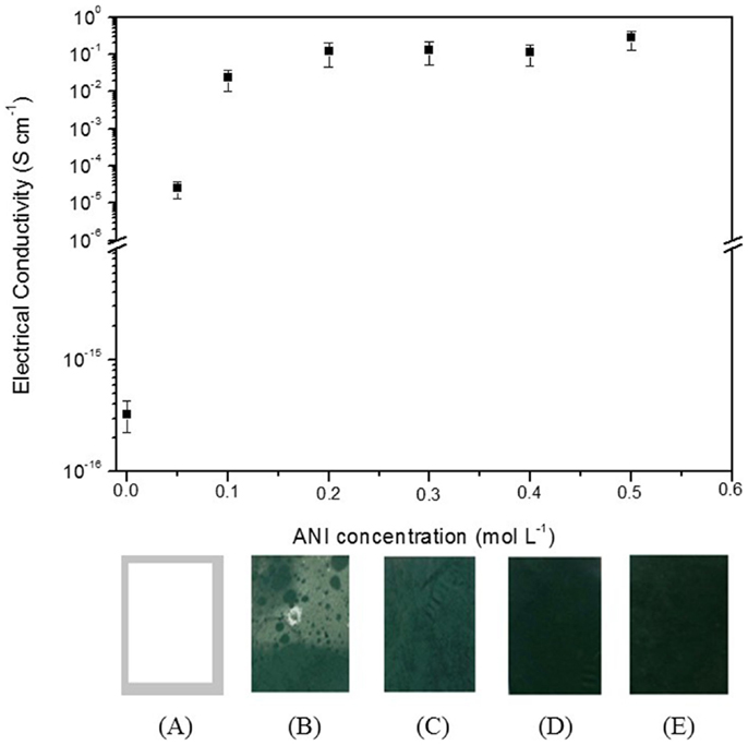
Figure 1. Electrical conductivity of PVDF/PANI mats as function of aniline concentration in the polymerization medium. Digital photographs of (A) PVDF and PVDF/PANI mats with monomer concentration of (B) 0.05 mol L−1, (C) 0.1 mol L−1, (D) 0.3 mol L−1, and (E) 0.5 mol L−1.
The influence of polymerization time on the electrical conductivity of PVDF/PANI was also evaluated (Figure 2) by using a monomer concentration of 0.3 mol L−1. During polymerization, the PVDF mats turn from white to green within 3 h of reaction, indicating a PANI coating on the PVDF fibers. However, this membrane displays a slightly low electrical conductivity. After 6 h, the electrical conductivity does not depend on the reaction time and remaining practically constant.
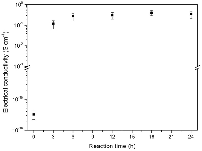
Figure 2. Electrical conductivity as function of reaction time of PVDF/PANI mats obtained with aniline concentration of 0.3 mol L−1.
The SEM micrographs of PVDF/PANI mats obtained by using different ANI concentration in the polymerization and electrospun PVDF are shown in Figure 3. The electrospun PVDF mat (Figure 3A) is constituted of three-dimensional network structure with randomly oriented fibers, with diameter of 0.8 ± 0.2 μm. The PVDF/PANI mats synthesized through different ANI concentration (Figures 3B–D) comprising PANI continuous layer on the PVDF fibers surfaces. With increasing the ANI content, the conducting layer thickness increases and some PANI in the form of agglomerates can be observed on the fiber surfaces (Figure 3D). This morphology is responsible for the electrical conductivities of the membranes, which are quite similar to that found for neat PANI.
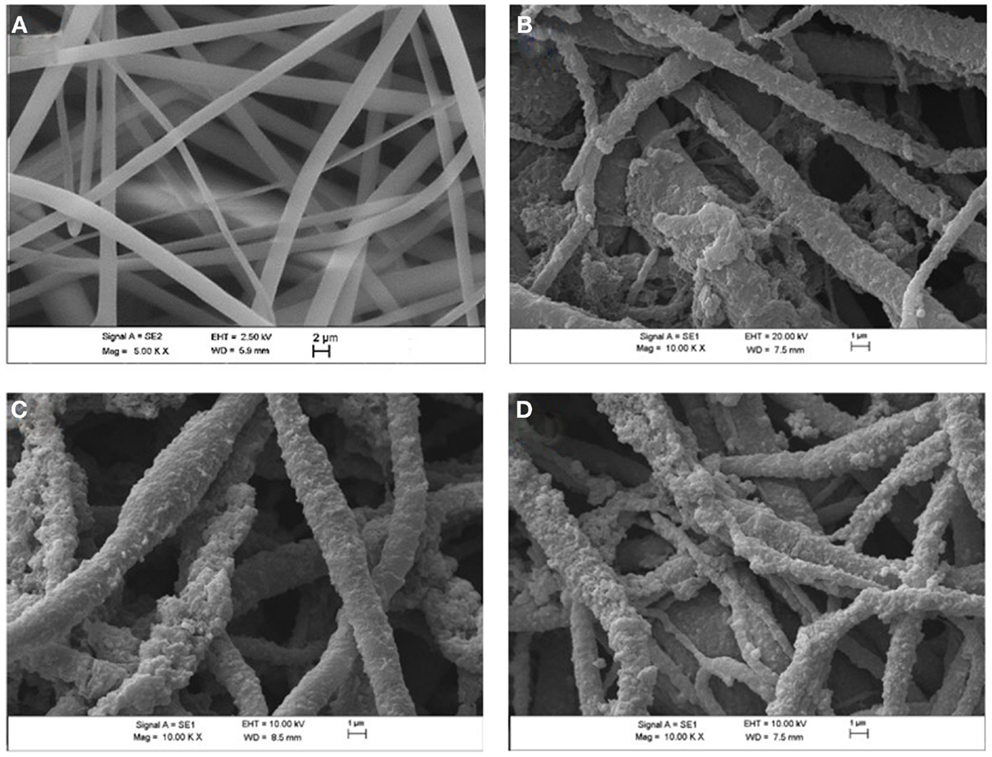
Figure 3. Scanning electron microscope micrographs of (A) electrospun PVDF mats, (B) PVDF/PANI [0.1], (C) PVDF/PANI [0.3], (D) PVDF/PANI [0.5] after 6 h of reaction.
Table 1 shows the elemental analysis obtained by CHN, the PANI content estimated by elemental analysis and the tensile properties of PVDF before and after coating with PANI. Considering that nitrogen is absent in the PVDF structure, the PANI amount incorporated on the PVDF surface during the in situ oxidative polymerization was determined by the nitrogen difference in the neat PANI and PANI-coated PVDF fibers mats, according to the procedure described in the literature (Merlini et al., 2014b). The PANI amount deposited on the PVDF fibers increases significantly with increasing monomer concentration. PVDF/PANI mats exhibit PANI content of 11.6, 28.4, and 39.8 wt% for ANI concentration of 0.1, 0.3, and 0.5 mol L−1, respectively. PVDF/PANI [0.1] membrane displays small amount of PANI and hence, it presents lower electrical conductivity [(2.4 ± 0.4) × 10−2 S cm−1] than that found for membranes with higher PANI content. On the other hand, PVDF/PANI mats with approximately 28 and 40 wt% of PANI display electrical conductivity quite similar to that found for neat PANI. This behavior indicates that for these ANI concentrations, a uniform layer is formed on the fiber mats reaching maximum electrical conductivity of 0.1 S cm−1.
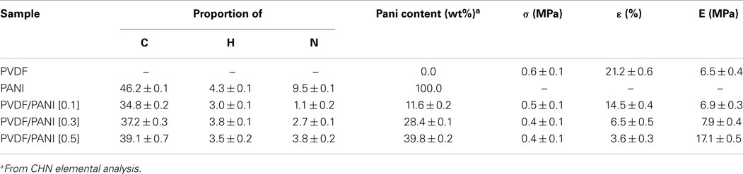
Table 1. Elemental analysis, PANI content, and tensile properties of electrospun PVDF, PVDF/PANI mats.
Figure 4 shows the representative stress–strain curves of electrospun PVDF and PANI-coated PVDF mats. PVDF mat shows typical ductile behavior with 21.2 ± 0.6% of elongation at break, while the tensile strength and Young modulus are 0.6 ± 0.1 and 6.5 ± 0.4 MPa, respectively. The tensile strength of the PANI-coated PVDF composites remains almost the same, regardless the amount of ANI used in the synthesis, as shown in the Table 1. On the other hand, a significant increase in the Young modulus and a decrease in elongation at break are observed with increasing the PANI concentration. These results may be attributed to the rigidity of PANI and to the presence of adhered PANI layers that improve the interfiber bonding, reducing the mobility of the PVDF fibers.
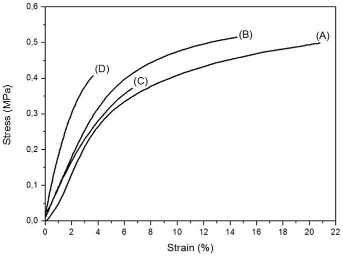
Figure 4. Representative stress–strain curves of (A) electrospun PVDF mats, (B) PVDF/PANI [0.1], (C) PVDF/PANI [0.3], and (D) PVDF/PANI [0.5].
The thermogravimetric curves of PANI, electrospun PVDF, and PVDF/PANI mats are reported in Figure 5. The electrospun PVDF mat exhibits only one weight loss at 469°C (midpoint from DTG), which is attributed to the decomposition of polymer chains with a residual weight of 30.5% at 700°C (Zhong et al., 2012; Ramôa et al., 2014). The neat PANI presents two main weight loss stages. The first stage with maximum at 105°C is related to the presence of moisture. The second one with weight loss from 277°C up to 390°C is attributed to degradation polymer backbone. The PVDF/PANI mats start to decompose at lower temperatures than neat PVDF. The degradation profile of the PVDF/PANI [0.1] is quite similar to the PVDF. However, increasing the PANI content on the fibers surface, the onset temperature of the mats decreases. However, it is possible to observe that, the PANI deposited on the fibers surface starts to decompose at higher temperature when compared with neat PANI. This behavior can be attributed to the dipole–dipole interaction between the –F− (–C–F) groups of PVDF and the H+ (=N–H) groups of PANI (Merlini et al., 2014b).
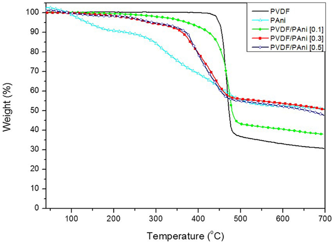
Figure 5. TG curves of neat PANI, electrospun PVDF, and PVDF/PANI mats prepared with different ANI concentrations.
The FTIR spectra of neat PANI, electrospun PVDF, and PVDF/PANI mats are shown in Figure 6. In the FTIR spectrum of PVDF, absorption bands associated to the β, α, and γ phases are identified. The absorption bands at 1402 and 876 cm−1 are attributed to the C–F stretching vibration of amorphous phase, while the bands at 1172 cm−1 assigned to the C–C bond (Gregorio and Borges, 2008; Yu and Cebe, 2009). The electrospun mats spectrum shows the presence of β phase (bands at 1274 and 837 cm−1), which offers the highest piezo-, pyro-, and ferro-electric properties and it is mainly interesting for sensing applications (Merlini et al., 2014a).The PANI spectrum exhibits absorption bands at 1540 and 1400 cm−1 associated to the quinone and benzene ring stretching deformations. The band at 1274 cm−1 corresponds to C–N+ stretching vibration (Trchová et al., 2004). The PVDF/PANI [0.1] exhibited overlapped absorption bands of both components. Furthermore, with increasing PANI content, the bands assigned to the PVDF groups practically disappear suggesting that PVDF fibers were completed coated with an external PANI layer.
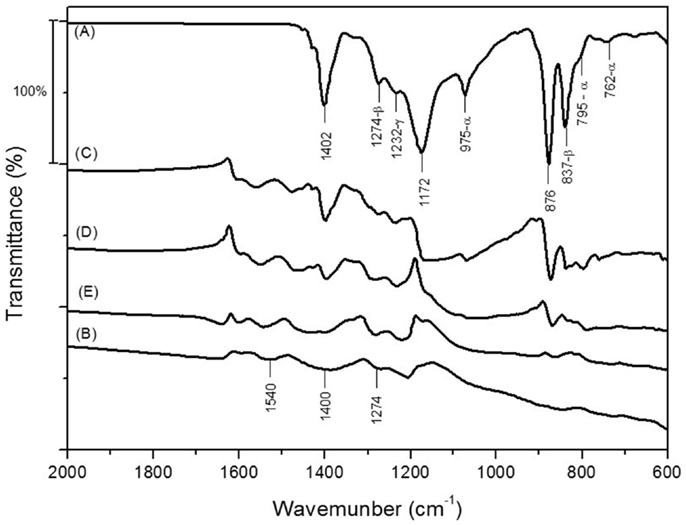
Figure 6. FTIR spectra of (A) electrospun PVDF mats, (B) neat PANI, (C) PVDF/PANI [0.1], (D) PVDF/PANI [0.3], and (E) PVDF/PANI [0.5].
Conclusion
In this study, an electrically conductive mat based on PVDF and PANI was successfully obtained through electrospinning technique and in situ oxidative polymerization. An efficient coating of the PVDF mats was obtained with ANI concentration higher than 0.1 mol L−1, wherein the fibers surface was coated with a PANI layer adhered on PVDF fibers. The electrical conductivity and the amount of PANI on the PVDF fibers surface increased with the increasing of monomer concentration. After 0.2 mol L−1 of ANI, the electrical conductivity of the PVDF/PANI mats reached a constant value, which was quite similar to that found for the neat PANI. After coating with PANI, the Young modulus enhanced significantly due to the presence of adhered PANI on the PVDF fibers, which increases the interfiber bonding. On the other hand, the elongation at break was reduced indicating that the membranes become more fragile probably because of the brittle nature of the PANI component. PVDF/PANI mats display a polymorph crystalline structure, with absorption bands associated to the β, α, and γ phases. PANI-coated electrospun PVDF mats developed in this work display, within others interesting features, three-dimensional fibers network structure, and good electrical conductivity, which demonstrates the potential to use as a chemicals sensor.
The two-step procedure described in this work, allow the development of electrospun mats with electrical conductivity similar to the neat ICP. This process is encouraged to be used when higher electrical conductivity is required, since studies in the literature (Merlini et al., 2014b) have reported that electrospun mats obtained from direct electrospinning show electrical conductivities as low as 10−15 S cm−1. Furthermore, the spinnability of the neat insulating polymer can be carry out more easily than its solution containing the ICP.
Conflict of Interest Statement
The authors declare that the research was conducted in the absence of any commercial or financial relationships that could be construed as a potential conflict of interest.
Acknowledgments
The authors gratefully acknowledge the financial support by Conselho Nacional de Desenvolvimento Científico e Tecnológico – CNPq, Coordenação de Aperfeiçoamento de Pessoal de Ensino Superior – CAPES, and Fundação de Amparo à Pesquisa e Inovação do Estado de Santa Catarina – FAPESC. We are sincerely thankful to Central Electronic Microscopy Laboratory, Santa Catarina Federal University (LCME-UFSC).
References
Aznar-Cervantes S., Roca M. I., Martinez J. G., Meseguer-Olmo L., Cenis J. L., Moraleda J. M., et al. (2012). Fabrication of conductive electrospun silk fibroin scaffolds by coating with polypyrrole for biomedical applications. Bioelectrochemistry 85, 36–43. doi: 10.1016/j.bioelechem.2011.11.008
Pubmed Abstract | Pubmed Full Text | CrossRef Full Text | Google Scholar
Bagheri H., Aghakhani A. (2012). Polyaniline-nylon-6 electrospun nanofibers for headspace adsorptive microextraction. Anal. Chim. Acta 713, 63–69. doi:10.1016/j.aca.2011.11.027
Pubmed Abstract | Pubmed Full Text | CrossRef Full Text | Google Scholar
Chen D., Miao Y. E., Liu T. (2013). Electrically conductive polyaniline/polyimide nanofiber membranes prepared via a combination of electrospinning and subsequent in situ polymerization growth. ACS Appl. Mater. Interfaces 5, 1206–1212. doi:10.1021/am303292y
Pubmed Abstract | Pubmed Full Text | CrossRef Full Text | Google Scholar
Chronakis I. S., Grapenson S., Jakob A. (2006). Conductive polypyrrole nanofibers via electrospinning: electrical and morphological properties. Polymer 47, 1597–1603. doi:10.1016/j.polymer.2006.01.032
Gregorio R., Borges D. S. (2008). Effect of crystallization rate on the formation of the polymorphs of solution cast poly(vinylidene fluoride). Polymer 49, 4009–4016. doi:10.1016/j.polymer.2008.07.010
Huang J., Virji S., Weiller B. H., Kaner R. B. (2004). Nanostructured polyaniline sensors. Chemistry 10, 1314–1319. doi:10.1002/chem.200305211
Huang W., Edenzon K., Fernandez L., Razmpour S., Woodburn J., Cebe P. (2010). Nanocomposites of poly(vinylidene fluoride) with multiwalled carbon nanotubes. J. Appl. Polym. Sci. 115, 3238–3248. doi:10.1002/app.31393
Huang Z.-M., Zhang Y. Z., Kotaki M., Ramakrishna S. (2003). A review on polymer nanofibers by electrospinning and their applications in nanocomposites. Compos. Sci. Technol. 63, 2223–2253. doi:10.1016/s0266-3538(03)00178-7
Ji L., Lin Z., Li Y., Li S., Liang Y., Toprakci O., et al. (2010). Formation and characterization of core-sheath nanofibers through electrospinning and surface-initiated polymerization. Polymer 51, 4368–4374. doi:10.1016/j.polymer.2010.07.042
Lin Q. Q., Li Y., Yang M. J. (2012). Polyaniline nanofiber humidity sensor prepared by electrospinning. Sens. Actuators B Chem. 161, 967–972. doi:10.1016/j.snb.2011.11.074
MacDiarmid A. G., Jones W. E., Norris I. D., Gao J., Johnson A. T., Pinto N. J., et al. (2001). Electrostatically-generated nanofibers of electronic polymers. Synth. Met. 119, 27–30. doi:10.1016/s0379-6779(00)00597-x
Malinauskas A. (2001). Chemical deposition of conducting polymers. Polymer 42, 3957–3972. doi:10.1016/S0032-3861(00)00800-4
Merlini C., Almeida R. S., d’Ávila M. A., Schreiner W. H., Barra G. M. O. (2014a). Development of a novel pressure sensing material based on polypyrrole-coated electrospun poly(vinylidene fluoride) fibers. Mater. Sci. Eng. B 179, 52–59. doi:10.1016/j.mseb.2013.10.003
Merlini C., Barra G. M. O., Medeiros Araujo T., Pegoretti A. (2014b). Electrically pressure sensitive poly(vinylidene fluoride)/polypyrrole electrospun mats. RSC Adv. 4, 15749–15758. doi:10.1039/C4RA01058B
Norris I. D., Shaker M. M., Ko F. K., Macdiarmid A. G. (2000). Electrostatic fabrication of ultrafine conducting fibers: polyaniline/polyethylene oxide blends. Synth. Met. 114, 109–114. doi:10.1016/s0379-6779(00)00217-4
Ramôa S. D. A. S., Merlini C., Barra G. M. O., Soares B. G. (2014). Obtenção de nanocompósitos condutores de montmorilonita/polipirrol: efeito da incorporação do surfactante na estrutura e propriedades. Polímeros 24, 57–62. doi:10.4322/polimeros.2014.051
Pubmed Abstract | Pubmed Full Text | CrossRef Full Text | Google Scholar
Sarvi A., Chimello V., Da Silva A. B., Bretas R. E. S., Sundararaj U. (2014). Novel semiconductive coaxial electrospun nanofibers. Plast. Res. Online. doi:10.2417/spepro.005274
Srinivasan S. S., Ratnadurai R., Niemann M. U., Phani A. R., Goswami D. Y., Stefanakos E. K. (2010). Reversible hydrogen storage in electrospun polyaniline fibers. Int. J. Hydrogen Energy 35, 225–230. doi:10.1016/j.ijhydene.2009.10.049
Trchová M., Šedenková I., Tobolková E., Stejskal J. (2004). FTIR spectroscopic and conductivity study of the thermal degradation of polyaniline films. Polym. Degrad. Stab. 86, 179–185. doi:10.1016/j.polymdegradstab.2004.04.011
Yu L., Cebe P. (2009). Crystal polymorphism in electrospun composite nanofibers of poly(vinylidene fluoride) with nanoclay. Polymer 50, 2133–2141. doi:10.1016/j.polymer.2009.03.003
Yu Q.-Z., Dai Z.-W., Lan P. (2011). Fabrication of high conductivity dual multi-porous poly (l-lactic acid)/polypyrrole composite micro/nanofiber film. Mater. Sci. Eng. B 176, 913–920. doi:10.1016/j.mseb.2011.05.017
Pubmed Abstract | Pubmed Full Text | CrossRef Full Text | Google Scholar
Yu Q.-Z., Shi M.-M., Deng M., Wang M., Chen H.-Z. (2008a). Morphology and conductivity of polyaniline sub-micron fibers prepared by electrospinning. Mater. Sci. Eng. B 150, 70–76. doi:10.1016/j.mseb.2008.02.008
Pubmed Abstract | Pubmed Full Text | CrossRef Full Text | Google Scholar
Yu Q. Z., Li Y., Wang M., Chen H. Z. (2008b). Polyaniline nanobelts, flower-like and rhizoid-like nanostructures by electrospinning. Chin. Chem. Lett. 19, 223–226. doi:10.1016/j.cclet.2007.12.005
Keywords: polyaniline, poly(vinylidene fluoride), electrospinnig, conductive membranes, in situ polymerization
Citation: Merlini C, Barra GMO, Ramôa SDAS, Contri G, Almeida RS, d’Ávila MA and Soares BG (2015) Electrically conductive polyaniline-coated electrospun poly(vinylidene fluoride) mats. Front. Mater. 2:14. doi: 10.3389/fmats.2015.00014
Received: 03 December 2014; Accepted: 08 February 2015;
Published online: 23 February 2015.
Edited by:
Kyriaki Kalaitzidou, Georgia Institute of Technology, USAReviewed by:
Peng-Cheng Ma, Chinese Academy of Sciences, ChinaChung Hae Park, Ecole Nationale Supérieure des Mines de Douai, France
Copyright: © 2015 Merlini, Barra, Ramôa, Contri, Almeida, d’Ávila and Soares. This is an open-access article distributed under the terms of the Creative Commons Attribution License (CC BY). The use, distribution or reproduction in other forums is permitted, provided the original author(s) or licensor are credited and that the original publication in this journal is cited, in accordance with accepted academic practice. No use, distribution or reproduction is permitted which does not comply with these terms.
*Correspondence: Claudia Merlini and Guilherme Mariz de Oliveira Barra, Department of Mechanical Engineering, Universidade Federal de Santa Catarina, Campus Universitário Trindade, Caixa Postal 476, Florianópolis, Santa Catarina 88040-900, Brazil e-mail: dra.claudiamerlini@yahoo.com.br; g.barra@ufsc.br