
Design of Particle Dampers for Laser Powder Bed Fusion


Institute of Product Development (IPeG), Gottfried Wilhelm Leibniz Universität Hannover, An der Universität 1, 30823 Garbsen, Germany
*
Author to whom correspondence should be addressed.
Appl. Sci. 2022, 12(4), 2237; https://doi.org/10.3390/app12042237
Submission received: 11 January 2022
/
Revised: 4 February 2022
/
Accepted: 18 February 2022
/
Published: 21 February 2022
(This article belongs to the Topic Additive Manufacturing)
Abstract
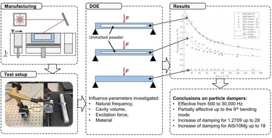
:Additively manufactured particle dampers can significantly improve component damping. However, if designed incorrectly, the damping can be worsened. For the design of additively manufactured particle dampers, there are not yet sufficient design rules and models to describe the effect due to numerous design parameters. The research question answered in this paper describes how the effect of particle damping can be characterised as a function of excitation force and excitation frequency for different cavity sizes. To characterise the effect of particle damping, a 33 full factorial test plan is constructed, and the damping is determined experimentally. It is shown that the damping can be reliably evaluated with the circle-fit method. The effect of particle damping is investigated for beams made of AlSi10Mg, 1.2709 and Ti6Al4V. As a result, a positive effect of the particle damping in a frequency range from 500 to 30,000 Hz and partly up to the 9th bending mode can be proven. It is shown that, for the first bending mode, there is an optimum at approx. 2000 Hz. For the optimum, the increase of the damping for the tool steel 1.2709 to 28 and for the aluminium alloy AlSi10Mg to 18 can be proven.
1. Introduction
The rapid development of systems in additive manufacturing towards ever-larger build spaces and build rates requires a rethink in product development [1]. In the future, the focus of Design for Additive Manufacturing (DfAM) will no longer be predominantly on components, but rather on assemblies [2,3,4,5]. In the best case, the assembly can be manufactured in one piece, according to the principle of the one-piece machine [6]. In order to realise the goal of the one-piece machine as best as possible, a multitude of physical effects must be understood and integrated into the component: so-called effect engineering [7].
In the field of additive manufacturing, especially in powder bed-based processes, the effect of particle damping represents a hitherto little-researched but very effective method for reducing vibrations [7,8,9,10,11,12,13,14,15,16,17,18,19,20]. Particle dampers produced by laser powder bed fusion (LPBF) can reduce vibrations by more than a factor of 20 in a wide frequency range [7,10,12].
In the field of product development, the use of additively manufactured particle dampers offers potential by solving the conflict between high stiffness and high damping [7,8,11]. For example, particles can be integrated in the area of the neutral fibre and components can be optimised in terms of mass, stiffness and damping. Since the mass, production time and costs hardly increase due to the functional integration of the particle damping effect in the field of additive manufacturing, this is also referred to as “damping for free” [7].
Due to numerous design parameters and interactions that are still not fully understood, research on additively manufactured particle dampers is still in its infancy [7]. As a result, detailed and universally valid design methods and tools do not yet exist. In addition, modelling is challenging due to highly non-linear properties [21,22,23]. Initial approaches to describing the effect of particle damping focus on limited parameter studies on additively manufactured primitives [7,9,10,12,13,14,16,17]. Isolated demonstrators such as cutting tool holders, braking discs or motorcycle triple clamps have also been considered [8,16,18]. The studies have in common that the transferability of the findings to other applications is missing. However, the range of possible applications for particle dampers is large. For example, conventionally manufactured particle dampers are already used to reduce vibrations in electronics, either to protect the electronics from damage (rocket launch) or to ensure high-precision measurement tasks (optical applications) [24,25]. In addition to mechanical vibrations, thermally induced vibrations are increasingly occurring in high-precision measurement tasks, which could be reduced by particle dampers [26]. Other areas of application are turbine components, antennas or surgical instruments [21].
This paper aims to identify the influence of excitation force, excitation frequency and cavity size on the effect of particle damping by developing a 33 full factorial experimental design. Beams are selected as test specimens, which are excited to vibrate from 10 to 180 N using an automated impulse hammer. The beams are manufactured in different dimensions in order to vary the natural frequency and thus characterise the frequency-dependent damping. Furthermore, in addition to the first bending mode, the higher modes are also evaluated. Thus, a frequency range from 500 Hz to 30,000 Hz can be analysed. Furthermore, it is to be analysed to what extent these findings are similar between the material classes of aluminium, steel and titanium. For this purpose, tests will be carried out on beams made of aluminium AlSi10Mg, tool steel 1.2709 and titanium Ti6Al4V. As a result of this contribution, these influencing parameters will be provided in the form of design curves. This should help the designer to reduce the vibration amplitudes to the desired level and to estimate the damping. Furthermore, these findings are to form the basis for the validation of a mechanical model for laser beam-melted particle dampers. Accordingly, initial assumptions are already being made in order to build a mechanical model that is specifically tailored to additive manufacturing.
2. Review
One possibility to increase the damping in laser beam melted structural components is to integrate the effect of particle damping [7,8,9,10,11,12,13,14,15,16,17,18,19,20]. By means of particle dampers, produced by laser powder bed fusion (LPBF), vibrations can be reduced by more than a factor of 20 in some cases [7,10,12]. The powder bed-based process allows the particles to be integrated directly into the cavities of the component during the manufacturing process, thus further increasing the high degree of functional integration. In the field of product development, the use of additively manufactured particle dampers offers potential in that the conflict of goals between high stiffness and simultaneous high damping can be solved [7,8]. For example, particles can be integrated in the area of the neutral fibre and components can be optimised in terms of mass, stiffness and damping. Figure 1 shows an exemplary manufacturing process of laser beam melted particle dampers using the example of a damped gear wheel.
With particle dampers, the energy is dissipated by combined loss mechanisms due to friction and impact processes between the particles themselves and the interaction between the particles and the wall. A schematic representation is shown in Figure 2.
In addition to the already mentioned advantages of simple and low-cost design [21] and broadband damping [7,27,28,29,30], particle dampers are characterised by good performance in harsh environmental conditions. These include, in particular, use under the influence of high temperatures [21,31,32] (from cryogenic to high-temperature applications of 2000 °C) and contamination [21,33] (oil, dust, etc.). In addition, they show hardly any wear and are low-maintenance [21]. Furthermore, particle dampers can increase component life due to the increased damping.
Due to these and other advantages, particle dampers have been used successfully for several hundred years to reduce vibrations [21]. In contrast, the use of particle dampers in additive manufacturing is not yet widespread and is described briefly below.
2.1. Applications and Research Activities
Scott-Emuakpor et al. analysed forced vibrations of particle-damped beams manufactured of Inconel 718 [12,13,19,20,34,35] and AISI 316L stainless steel [14,35]. The influence of the cavity position and number for a clamped beam are investigated. The beams are excited to vibrate by means of a shaker and the vibration response of the beam is measured with a laser vibrometer and that of the shaker with an acceleration sensor. Due to the beam clamping on the shaker, no significant increase in the component damping for the particle-filled beams could be demonstrated, such that the focus of the evaluation was placed on the second and third bending modes. It was shown that the component damping could be increased by up to a factor of six, even with a low cavity volume of only 4% in relation to the beam volume [12,34]. These results were then used to build a model based on a regression analysis [19,20,35].
Schmitz et al. investigated the effect of particle damping using laser beam melted walls of 316L by pulse hammer excitation [10]. Here, the damping was characterized as a function of cavity height for the first three modes in a frequency range up to 3000 Hz. It was found that the effect of particle damping increases with increasing cavity height as well as at higher modes. For the particle-damped sample with the largest cavity, a maximum damping ratio of particle-damped to fully-fused of 225 was realized at the third mode [10]. Furthermore, a change in the natural modes of vibration has been shown for the particle-damped components.
Künneke and Zimmer applied the performance approach of Yang [36] to evaluate the effect of particle damping independent of a main vibrating structure [17]. This made it possible to map only the dynamics of the particles and derive maps of the loss factor for the 316L material. The maps are generated for different primary volumes and void volumes. In addition, the shape of the cavity is varied (cube cuboid, cylinder and sphere). Characteristic damping bands in the investigated frequency range up to 5000 Hz could be created [17]. In further work, Künneke and Zimmer were able to demonstrate that the sound radiation of a laser beam melted anchor plate for an electromagnetic spring-applied brake could be reduced by 7.86 db(c) [16].
2.2. Design Parameter
So far, there are no reliable modelling methods for additively as well as conventionally manufactured particle dampers. This is due to both the highly nonlinear properties of particle damping and the numerous design parameters, such as frequency, excitation level, and shape of the cavity [22,23]. The best modelling approaches are realised using the discrete element method (DEM) [38]. However, due to the large number of particles, this is very computationally and time intensive and therefore not practical for millions of particles. Models with an even higher degree of simplification only consider a small number of particles, such that the particle dynamics are not sufficiently represented. The results of the substitute model are therefore only valid within a narrow parameter window. Furthermore, it is not practicable to investigate more than 20 influencing parameters in one study, as the experimental or simulation effort would be excessive [7,21]. The derivation of design recommendations is also difficult when local maxima and minima occur in the curves of the damping [7,14]. For this reason, the focus is often placed on the influencing parameters that seem to have the greatest influence on the damping. As presented in the previous section, some knowledge is already available on the design of additively manufactured particle dampers. However, these are not sufficient. For conventionally manufactured particle dampers, a number of investigation results and correlations are already available [22,23,27,28,31,32,33,38,39,40], which will be discussed in the following.
2.2.1. Excitation Level
Fowler et al. found that there is an optimum excitation level for particle damping that is specific to each application. Above or below this level, damping decreases. A crucial parameter on which the optimal excitation level depends is the size of the cavity, especially in the excitation direction [23].
2.2.2. Particle Mass
In addition to the excitation force, particle mass is one of the most important factors for energy dissipation [41]. Even a relatively low mass ratio can realize a significant reduction in amplitude [27]. Fowler et al. found that particle mass affects not only the amplitude of vibration but also the natural frequency [23]. Overall, it should be considered that by adjusting the particle mass, the packing density and number of particles are also adjusted.
2.2.3. Packing Density
The packing density is calculated from the ratio between the volume of all particles related to the volume of the cavity. If the packing density is too low, the number of particles and thus the number of friction and impact processes is low, which leads to low energy dissipation. On the other hand, when the packing density is 100%, the particles can no longer move, so the energy dissipation is also low [39]. Studies on conventionally manufactured particle dampers have shown that the optimum packing density is between 40 to 80% [39,42,43,44]. Even though in LPBF the packing density can hardly be varied, by default the packing density is in a range between 50–60% [45] and is thus in an optimal range for particle damping.
2.2.4. Dimensions/Cavities
In the cavities, the particles are compressed in the direction of gravity. This allows the particles at the bottom in particular to move less than the particles at the top. This leads to a limitation of the maximum effective cavity size in the gravitational direction [23,35]. It follows that the size of the cavity in the gravitational direction must be determined individually for each application [39]. On the other hand, the damping decreases if the size of the cavity is too small [27]. A basic recommendation is that the cavity should always be placed at the point of greatest deflection or in the region of highest kinetic energy [39].
2.3. Experimental Characterization of Damping
By means of the circle-fit method, relevant modal parameters such as the natural frequency and the damping ratio can be calculated. This method evaluates the frequency response function (FRF) near the natural frequencies and plots the result in the complex plane in the form of a Nyquist curve [46,47]. For this purpose, the real part is plotted over the imaginary part. Ideally, the points can be connected in such a way that a circle results. The corresponding calculation principles can be looked up in the relevant literature, cf. [46].
The circle-fit method has already been successfully used to characterize the effect of particle attenuation for beams made of AlSi10Mg in Ehlers et al. [7]. The beams—supported on foam—were excited to vibrate using an automated impulse hammer excitation and the damping of the first bending mode was evaluated. A frequency range from 600 Hz to 18,000 Hz was investigated. At selected frequencies, the damping was increased by a factor of 20 in some cases compared with the fully-fused beam. It was found that the damping curve is hyperbolic and can be assumed to be constant at higher forces of 100 N and above. Furthermore, vertically printed beams were found to exhibit higher particle attenuation than the horizontally printed beams. As a central result, design curves for excitation force, excitation frequency and cavity size were determined. Finally, a procedure was presented to transfer the results from the design curves to other components.
Figure 3 shows an exemplary frequency response function and the corresponding circle-fit of Ehlers et al. for a particle-damped beam [7]. Despite the nonlinear effects of particle damping, the circle-fit method could be successfully applied. However, only the immediate area of resonance could be evaluated, such that a circle section in the complex plane always resulted.
3. Experimental Methodology
In this section, the methodological procedure for characterizing the effect of particle damping is presented and builds on the preliminary work from [7,8]. As can be seen from the previous section, the effect of particle damping is an effective measure for vibration reduction. A large number of influencing and design parameters need to be considered to describe the effect. However, due to the high degree of non-linearity, modelling is challenging, so in the present work a design of experiment (DoE) of the effect in the form of an impulse hammer excitation is performed. In doing so, the design space is described exploratively on primitives (beams). The relationships established here can be applied to other dynamic systems with similar modal parameters, such as the same natural frequency. Thus, the results can also be transferred to real applications, such as cutting tool holders, motorcycle triple clamps or wheel carriers. Figure 4 shows an overview of the methodical procedure in the form of a flow chart. As a result of this paper, the influencing parameters force, frequency, cavity volume and material are available in the form of design curves. Based on these design curves, mechanical models for laser beam melted particle dampers can be built and validated in further work.
3.1. Test Plan
A cuboid beam with a cuboid cavity is chosen to characterise the effect of particle damping. By positioning the beams on a longitudinal edge, support structures in the cavity can be dispensed with due to self-supporting structures (see Figure 5). The beams are thus manufactured horizontally.
The basis of the experimental design is a 33 full factorial experimental design. This means that three influencing factors are analysed and each influencing factor has three supporting points. This results in a total of 27 parameter combinations. In order to be able to characterise the frequency-dependent course of the particle damping, the natural frequency of the beams is defined as the first parameter, which results from the geometric dimensions of the beams. The second influencing factor is the ratio ζ between particle volume and beam volume and is thus an indirect description of how much particle mass in relation to the beam mass is in the beam. Here, beams with a cavity of 0% (fully-fused beam), 10% and 20% are examined.
As a third parameter, the material is varied. The largest application areas for the production of additively manufactured end products are aerospace and the automotive industry [48]. For aerospace, aluminium or titanium alloys are particularly relevant, especially for brackets, components for electronic mounting or turbine blades (titanium). In the automotive industry, aluminium can be used for motorcycle triple clamps or brake shoe holders, for example. Furthermore, steel alloys are relevant for the additive manufacturing of gears or brake discs in the automotive industry or also for cutting tool holders in plant engineering. It should be emphasised that the initial material of the particles and the beams must be the same and only the material combination as a whole can be changed. In total, three different material classes are varied, namely aluminium AlSi10Mg, tool steel 1.2709 and titanium Ti6Al4V. In addition, two boundary conditions are introduced. The first boundary condition describes the length of the cavity and is defined as lCavity = 0.8 lbeam. Additionally, the width ratio ξ = bCavity/bbeam of the cavity has to be specified and is defined as ξ = 2.5 × ζ.
Previous studies have shown that the frequency response functions of the beams made of AlSi10Mg with dimensions of 10 × 10 × 200 mm3 were strongly influenced by the effect of particle damping. This meant that the damping could not be reliably detected [7]. For this reason, a total of four interpolation points of the natural frequency are analysed in the experimental plan (see Table 1).
In addition, two further parameters, the excitation force and the excitation direction, are varied during the experiment. The excitation force varies from 10 N to 180 N in steps of 10 N to 100 N and in steps of 40 N to 180 N. However, these values are deviated from in individual cases if, for example, the acceleration sensor reaches its saturation limit.
For the clear assignment and orientation of the beams during the test, the beam number and a coordinate system are printed on the front surfaces of all beams. The following notation is used:
- x-direction: Coater travel path
- y-direction: Perpendicular to coater travel path
- z-direction: Build direction
To transfer the results to other applications, the variables of cavity height to beam height, cavity width to beam width, cavity volume and natural frequency can be used.
Previous experiments in AlSi10Mg have shown that the standard deviation of the attenuation of three printed beams of the same topology is low [7], so that only one beam per parameter is produced in the following.
The beams were produced in nine batches, although not all batches are considered in this paper. It should be noted here that not all parameters are numbered consistently, as not all printed beams are analysed in this paper. However, with regard to research data management and comparison with other works, this numbering leads to a clear and consistent allocation.
3.2. Machine and Process Parameter
The beams with parameters 1 to 31 are made of the aluminium alloy AlSi10Mg on the LPBF system EOS M280. The beams made of tool steel 1.2709 (par. 40 to 51) are also produced on the LPBF system EOS M280. On the other hand, the beams with the titanium alloy Ti6Al4V (par 52 to 63) are produced on the LPBF system Concept Laser M2. For the production of all beams, the standard parameter sets of the respective manufacturers are selected for the respective material. The layer thickness is 30 μm for all beams. The average grain size D50 of the powders was 47 μm for the aluminium alloy, 31 μm for the steel alloy and 38 μm for the titanium alloy. The aluminium and steel alloy beams are removed from the building platform with a saw. No heat treatment is carried out. Due to the high residual stresses of titanium, before the support structures are removed, the components together with the build platform are stress-relieved for 6 h in an argon inert gas atmosphere at 840 °C and then the components are removed from the build platform by wire erosion. The support structures of the aluminium components could be broken off, whereas the support structures of the steel and titanium alloy beams were milled off. Subsequently, all components were sandblasted. In order to obtain detailed information about the packing density, CT scans of selected beams were carried out. In addition, the mass of all beams was measured in order to draw conclusions about the particle mass.
3.3. Experimental Setup
To characterise the damping, the beams are placed on foam at the ends and an acceleration sensor M353B17 from PCB Piezotronics is mounted centrally on the underside of the beam. The advantage of mounting the beams on foam is that no clamping is required and therefore, in comparison to Scott-Emuakpor et al. [12], the first beam bending mode can already be evaluated. The background to this is that parasitic friction occurs in clamped components as a result of component vibrations, which has a decisive influence on component damping. To excite the beam to vibration, an automated impulse hammer (5800SL from Dytran) is used (see Figure 6). The automation of the impulse hammer is realised by a stepper motor. This achieves a high repeat accuracy and avoids double hits. In order to be able to evaluate the manufacturing-related influence of anisotropy, the beams are excited to vibrate in both x and y directions. Furthermore, 10 different force levels per side are investigated and the hits are made centrally on the top of the beam. Using the data acquisition device VibRunner and the software m+p Analyzer from m+p international, it is possible to calculate the frequency response functions (FRF) from the recorded time data of the impulse hammer and the acceleration sensor. The damping in the frequency domain can then be calculated using the circle-fit method.
4. Results
4.1. Fully-Fused Beams
To evaluate the effect of particle damping, the fully-fused (solid) beams are first characterised. For this purpose, the frequency response function is evaluated by means of the circle-fit method near the resonance, cf. [7]. The damping curve of the fully-fused beams is shown in Figure 7 for the alloys AlSi10Mg, 1.2709 and Ti6Al4V (parameter 1, 12, 15, 18, 42, 45, 48, 51, 54, 57, 60 and 63).
Each point shown was averaged by at least five measured values at different forces. The natural frequencies were varied by the outer beam dimensions. Furthermore, slightly anisotropic material behaviour can be observed. The measured points of the natural frequency agree well with the analytical equation of the freely supported beam. The damping decreases with increasing frequency and can be approximated by a hyperbolic function. This formula relationship of the damping can also be explained by the formula relationships of the equivalent 1 degree of freedom model [7]. Using these formula relationships and Figure 7, it can be determined that the damping increases from steel to titanium to aluminium. The decisive influencing variables here are the modulus of elasticity and the density. This damping curve gives the designer an initial overview of the frequency-dependent damping of the fully-fused beams.
4.2. Particle Damped Beams
In the following section, the results of the particle-damped beams made of AlSi10Mg, 1.2709 and Ti6Al4V are presented. It starts with the analysis of the results from titanium, where an agglomeration of the powder inside the component is observed and consequently a low damping is realised. Subsequently, the focus is placed on comparisons between the damping of AlSi10Mg and 1.2709, which are divided into four measurement campaigns. The damping is evaluated from the first to the fifth bending mode in a frequency range from 500 to 30,000 Hz. For each outer beam dimension, one fully-fused and two powder-filled beams with a cavity of 10% and 20%, respectively, are manufactured. The powder-filled beams differ in the height of the cavity.
4.2.1. Titanium Beams
Compared to the beams made of AlSi10Mg and 1.2709 (Section 4.2.3, Section 4.2.4, Section 4.2.5 and Section 4.2.6), the beams made of titanium show no significant damping over the entire frequency range investigated up to 30,000 Hz. The reason for the low effect of particle damping can be attributed to the subsequent heat treatment. For the heat treatment, the titanium beams were stress-relieved for 6 h in an argon inert gas atmosphere at 840 °C. The powder in the beam was sintered by the heat treatment, so that the number of impact and friction processes during component vibrations was drastically reduced. By means of microscope images, it could be determined that the powder is strongly clumped and can be seen as a cohesive mass.
In order to improve the effect of particle damping for titanium, other strategies for heat treatment should be adopted in further work. Since no significant increase in damping could be realised by means of the particle-damped beams made of titanium (parameters 52–63), only the beams made of AlSi10Mg and 1.2709 will be analysed in the further course of the paper.
4.2.2. Determination of Particle Mass and Packing Density
Relevant parameters influencing the effect of particle attenuation are particle mass and packing density. For this reason, all beams are measured using a scale. The particle mass can then be calculated using Equation (1).
mP,x = mx − m0/V0 × Vx
From the CAD, the volumes Vx and V0 of the beams can be determined, whereas the masses mx and m0 of the printed beams can be measured with a scale. The variables marked with the index 0 indicate that they refer to the fully-fused (solid) beam, which has the same external dimensions as the particle-filled beam with the index x. The packing density ƞ can then be calculated using Equation (2).
Ƞx = ρP,x/ρ0 with ρP,x = mP,x/(V0 − Vx)
Here, ρP,x describes the equivalent density of the particle-filled cavity. It is assumed that the density of the unmelted particles corresponds to the density of the melted material. Possible influences that lead to a deviation between the theoretical and real particle mass and packing density are, on the one hand, the manufacturing deviations and, on the other hand, local porosities in the component. Table 2 shows the results for beam mass mB, particle mass mP and packing density ƞ.
4.2.3. First Measurement Campaign
In the following, the 5 × 5 × 200 mm3 beams made of AlSi10Mg and the 4.2 × 4.2 × 169 mm3 made of 1.2709 are analysed. Due to the limitations of the accelerometer, only forces up to 20 N and 25 N can be analysed. Figure 8a,b shows a selection of three frequency response functions each for an excitation force of Fz = 20 N. More detailed damping curves are shown as a function of different excitation forces and for the first, third and fifth mode in Figure 8c–h. The local maxima (resonances) in Figure 8a,b represent the odd bending modes. The local minima (anti-resonances) represent the even bending modes. Since the acceleration sensor is located at a vibration node for the even bending modes, only the odd bending modes can be evaluated. Using impulse hammer excitation, a frequency range of up to 18,000 Hz can be excited for the beams made of AlSi10Mg and up to 25,000 Hz for the beams made of 1.2709. It can be seen that the effect of particle damping is effective over the frequency range investigated. Table 3 shows the percentage reduction in amplitude due to the effect of particle damping compared to the fully-fused beam. However, the damping effect decreases from the second mode onwards.
Figure 8 also shows that the damping of the particle-damped beams increases significantly from the first to the third bending mode. Subsequently, the damping for all beams, except for the AlSi10Mg beam with a 10% cavity, decreases again for higher modes. From the results, it can be concluded that for the beams made of steel, a larger cavity consistently leads to higher damping than a smaller cavity. For the AlSi10Mg alloy, which is subject to strong fluctuations especially in the z-direction, no general statement can be made. Some of the damping curves show a characteristic curve, which can be described by a functional relationship. The damping curves are fitted by a hyperbolic function.
The damping of the particle-damped beams made of AlSi10Mg is higher for the first mode than that of the particle-damped beams made of 1.2709. However, it must be taken into account that the damping of the fully-fused beams is higher for the beams made of AlSi10Mg. Thus, the gain in damping is approximately the same for both materials. For the damping curves of the beams from the third and fifth mode, the damping values of AlSi10Mg are approx. 10 to 20% apart, whereby the tendency depends on the direction of the excitation force and cavity size. The frequency responses functions from the seventh mode onwards could no longer be reliably evaluated with the circle-fit method. However, it is evident from the frequency responses functions that the effect of particle damping can offer added value up to the 9th mode.
4.2.4. Second Measurement Campaign
In the following, the 10 × 10 × 200 mm3 beams of AlSi10Mg and the 8.4 × 8.4 × 169 mm3 of 1.2709 are analysed. A CT scan for a beam made of 1.2709 with a cavity of 20% is shown in Figure 9. It can be seen that the cavity is almost completely filled with powder. Due to the limitations of the accelerometer, only forces up to a maximum of 100 N can be analysed. Figure 10a,b shows a selection of three frequency response functions each for an excitation force of Fz = 50 N. By means of the impulse hammer excitation, a frequency range up to 30,000 Hz can be analysed. The evaluation of the measurement results showed, for all particle-damped beams, both for AlSi10Mg and 1.2709, that all frequency response functions of the first mode do not look like a classical resonance peak, as it is known from an equivalent 1 degree of freedom model. Figure 10c,d shows two exemplary frequency response functions of the particle damped beams with a cavity of 20% and an excitation force of Fz = 10 N. When using the circle-fit method to evaluate the measurement results, it was found that instead of one circle, two intertwined circles were characterised. This is an indication of further resonances in the examined frequency range, so that the circle-fit method is not suitable for the evaluation of this mode. Repositioning the beams on the foam did not change the characteristics either. By comparing the frequency responses, however, a clear reduction of the amplitude by up to 97% due to the effect of particle damping can be demonstrated (see Table 4). For this reason, the amplitude reduction was calculated for each excitation force and the factor of the amplitude reduction multiplied by the damping value of the fully-fused beams (Figure 10e,f). This made it possible to derive an equivalent damping.
In the following, the focus of the evaluation is placed on the third bending mode. For this purpose, detailed damping curves as a function of different excitation forces are shown in Figure 10g,h. For the third modes, it is noticeable that no more side resonances occur and the damping can again be reliably characterised with the circle-fit method. For the beams made of AlSi10Mg with a cavity of 10%, a direction-dependent damping characteristic is evident, whereas this does not occur for the beams made of 1.2709. The force-dependent damping curve for the beams with a cavity of 20% is approximately identical for the beams made of AlSi10Mg and 1.2709. In addition, a larger cavity leads to higher damping for both materials. The course of the damping could be described by a hyperbolic function.
In the fifth mode of the fully-fused beams made of AlSi10Mg, the frequency response functions for all force levels show a side resonance. As a result, the amplitudes of the particle-damped beams are consistently higher than those of the fully-fused beams. In the seventh mode, no pronounced resonance could be detected for the fully-fused beam. Consequently, the amplitudes of the particle-damped beams are also consistently higher than those of the fully-fused beams.
For the fifth mode of the beams from 1.2709, the damping of the fully-fused beams for an excitation in y-direction is strongly fluctuating (see Figure 11). It can be seen that the effect of particle damping in the y-direction does not make a significant contribution. On the other hand, there is an increase in damping for excitation in the z-direction. It is noticeable that the damping is higher for a small cavity. For the seventh mode, the measured values are even more subject to fluctuation, such that no significant information can be derived there.
4.2.5. Third Measurement Campaign
In the following, the 20 × 20 × 200 mm3 beams made of AlSi10Mg and the 16.9 × 16.9 × 169 mm3 made of 1.2709 are analysed. Due to the limitations of the accelerometer, only forces up to a maximum of 180 N can be analysed. Figure 12a,b shows a selection of three frequency response functions each for an excitation force of Fz = 100 N. More detailed damping curves are shown as a function of different excitation forces for the first and third mode in Figure 12c–f. By means of the impulse hammer excitation a frequency range up to 30,000 Hz can be analysed. It can be seen that the effect of particle damping is effective for the first and third mode. Table 5 shows the percentage reduction of amplitude due to the effect of particle damping compared to the fully-fused beam. The force-dependent course of the damping could be mapped by a hyperbolic function.
Several conspicuous features can be seen in the damping curves of AlSi10Mg. The damping curves for the small and large cavity are close to each other for the first mode. In the third mode, the damping curve of the small mode is even higher than the damping curve of the large cavity. One reason for both conspicuities may be the influence of the packing density (see Table 2), which is significantly lower for beam 23 than for all other beams. Furthermore, in the third mode for the small cavity only the damping in the z-direction is shown. This is due to the fact that the frequency response functions for an excitation in the y-direction could not be evaluated with the circle-fit method due to side resonances and noise.
For the first and third mode, the damping curves of AlSi10Mg and 1.2709 show good agreement for the larger cavity and for higher excitation forces. For smaller excitation forces, the damping of the beams made of 1.2709 is consistently greater. It is also noticeable that the damping of all fully-fused beams made of AlSi10Mg of the third mode is greater, especially in the y-direction. This means that the ratio of damping from particle-damped to fully-fused is greater for the beams made of 1.2709, especially for the large cavity, and thus the effect of particle damping is better. For both the beams made of AlSi10Mg and 1.2709, the damping of the third mode is lower than for the first mode.
For this measurement campaign, it can thus be seen that the damping decreases with increasing frequency. In measurement campaign 1, an opposite trend was observed, namely that the damping was highest in the second mode. This is sometimes due to the natural frequency. In measurement campaign 1, the second mode (highest damping) and the first mode of this measurement campaign are in the same order of magnitude.
4.2.6. Fourth Measurement Campaign
In the following, the 20 × 20 × 150 mm3 beams made of AlSi10Mg and the 16.9 × 16.9 × 126 mm3 made of 1.2709 are analysed. Due to the limitations of the accelerometer, only forces up to a maximum of 180 N can be analysed. Figure 13a,b shows a selection of three frequency response functions each for an excitation force of Fz = 100 N. More detailed damping curves as a function of different excitation forces for the first and third mode are shown in Figure 13c–f. By means of the impulse hammer excitation, a frequency range up to 25,000 Hz can be analysed. It can be seen that the effect of particle damping is effective for the first mode. Table 6 shows the percentage reduction of the amplitude due to the effect of particle damping compared to the fully-fused beam. The force-dependent course of the damping could be mapped by a hyperbolic function.
For the first mode, it can be seen for both materials that a higher damping can be realised due to the larger cavity. The damping curve is greater for the beams made of 1.2709 than for the beams made of AlSi10Mg.
In the third mode, the damping of the fully-fused beams in the z-direction and the particle-damped beams with a 10% cavity made of AlSi10Mg could not be characterised due to side resonances. The damping in the z-direction is higher for a small cavity. Furthermore, strong directional damping values are evident for the 20% cavity.
For the beams made of 1.2709, it can be seen that the damping in the y-direction is consistently 0.4% for the fully-fused beams, which is very high. Thus, the damping of the fully-fused beams in the y-direction is higher than the particle-damped beams with a cavity of 10% and is approximately in the same order of magnitude as the particle-damped beams with a cavity of 20%. For excitation in the z-direction, the damping of the fully-fused beams is shown to be low and the damping increases with increasing cavity size.
For the beams made of AlSi10Mg, it is shown that the damping values of the particle-damped beams of the third mode are in the same order of magnitude as that of the first mode. For the beams made of 1.2709, the damping decreases slightly from the first to the third mode.
4.2.7. Reproducibility and Error Consideration
In this section, statements are made on the reproducibility and error consideration of the results presented so far. This will be done using the beams from 1.2709 for the parameters 40–42 as an example. Figure 14a shows the force-dependent course of the damping for one hit per excitation level for these beams. The standard deviation for the small cavity is 0.02%. This leads to a relative error of 5% for a force of 140 N and a damping of 0.4%. For the large cavity, the relative error is 13.2%.
Figure 14b shows the force-dependent course of the damping for five hits per excitation level. It is noticeable that the value of the standard deviation on Figure 14a,b changes by approx. 10%, both for the small and the large cavity. This results in the relative error changing from 5% to 5.5% for the small cavity and from 13.2% to 11.7% for the large cavity. The deviation between one or five hits per excitation level is thus an order of magnitude smaller than the total error, so that one hit per excitation level is preferred in terms of result quality and experimental effort.
In Ehlers et al., several beams of AlSi10Mg were printed per parameter and the force-dependent damping was characterised [7]. It was found that the relative error due to the standard deviation is about 10%.
Thus, it can be stated for this test setup that a relative error of 10% to 15% should be considered. This is particularly relevant for the robust design of additively manufactured particle dampers.
5. Discussion
This paper shows for the first time a comparison between damping characteristics of the material classes of aluminium (AlSi10Mg) and steel (1.2709) in a frequency range from 500 to 30,000 Hz. It can be shown that the results correlate well between the material classes. The strong frequency- and force-dependent course of the damping is striking for both material classes. For high forces from 100 N, however, a constant damping curve related to the excitation force can be determined for both material classes. This constant damping measure is suitable as a design variable for determining the frequency-dependent damping. However, it should be taken into account that up to approx. 1300 Hz, the force-dependent damping increases until the asymptote is reached and decreases from 1300 Hz.
Figure 15 shows the frequency-dependent damping factor (damping of the particle-damped beams in relation to the damping of the fully-fused beams) for the first to the third mode. It is noticeable that the damping factor for the beams made of 1.2709 is significantly higher. This is mainly due to the lower damping of the fully-fused beams made of 1.2709 compared to the beams made of AlSi10Mg. Thus, with the same damping factor of the particle-damped beams of 1.2709 to AlSi10Mg, the damping factor of 1.2709 can be higher.
It can be seen that an increase in the damping factor can be realised for the first two modes by means of the effect of particle damping. However, the optimum in the damping factor of both material classes around 2000 Hz is striking. At lower frequencies, the deflection is greater for the same acceleration. Consequently, the beam deflection may be much greater than the relative movement between the particles and the beam. Xu et al. already stated that the limit value of the minimum excitation X0 × f2 should be greater than 3.5 m/s2 [49]. On the other hand, the particle deflection is too small at frequencies above 10,000 Hz. Thus, there is an optimum in the frequency range, here at 2000 Hz. Another explanation for the low damping effect at 650 Hz may be related to parasitic friction in the mounting on foam, so that the fully-fused beam already shows increased damping. To evaluate this influence, the measurements could be repeated again for beams suspended on strings.
Further, in investigations by Schmitz et al., it was found that for an impulse hammer excitation of walls (clamped on one side) the effect of particle damping at 767 Hz for a cavity of approx. 20% provides only a small added value [9]. Higher modes could be damped much better in Schmitz et al., but the higher modes of the walls differ significantly from the bending modes of the beams investigated here, so the measurements can only be compared with each other to a limited extent.
The frequency response functions of the bending modes at 1300 Hz are striking in the second measurement campaign. The frequency response functions of the beams made of AlSi10Mg as well as for 1.2709 show chaotic movements. A possible explanation could be stick-slip effects due to friction. These stick-slip effects depend on the excitation force and excitation frequency [50,51], which coincidentally occur more strongly with exactly this parameter combination. Another explanation could also be possible effects of dynamic vibration absorption, since the particle cluster has a large number of natural frequencies. One of the natural frequencies of the particle cluster could coincide with that of the beam in the parameter combination.
The 33 full factorial experimental design presented here should be extended in further work. In particular, further support points should be investigated for the natural frequency. During the evaluation of the first two measurement campaigns, disturbance variables occurred, which therefore need to be quantified by further support points. Furthermore, the cavity size and length should be investigated with more support points in order to be able to better describe the influencing variable of the cavity.
For the beams made of Ti6Al4V, it could be shown that the post heat treatment has an influence on the powder in the cavities and thus on the effect of particle damping. Overall, no significant damping could be characterised for the beams made of Ti6Al4V. Future work could investigate further strategies for post-process heat treatment or devise measures to resolve agglomeration in the post-process.
CT scans have shown that the beams are almost completely filled with powder. Accordingly, the free movement length of the particles is very small in relation to the height of the particle cluster. Using this knowledge, a mechanical model of particle damping can be built that is tailored to additive manufacturing by neglecting the free movement length. The error would thus be less than 10%. So far, the non-linear spring and damper forces due to the consideration of the free movement length have been a challenge in the modelling. These forces must be modelled as an sgn-function. Figure 16 shows a two degrees of freedom model of a particle damper for additive manufacturing. The spring stiffnesses of the individual particles can be determined using contact mechanics according to Heinrich Hertz. The total stiffness of the particles cp can be calculated from a combination of series and parallel circuits of the individual stiffnesses. The damping constant dp can then be calculated from the discrete element method (DEM). The friction force can be calculated using the calculation principles for the silo effect.
The spring stiffness c0 and the damping constant d0 can be calculated using classical methods of experimental modal analysis or mathematical models for linear systems. However, the particle dynamics are neglected. Nevertheless, the literature also shows that the particles could behave like a coherent mass in some conditions [52,53]. At least for this state of vibration, the model should have a high accuracy. How large the range (force range, frequency range and cavity size) is in which the model is valid must be clarified in further work. The further description of the model and evaluation based on the results presented here will be considered in further work. With a validated mechanical model, designers could simulate different parameter combinations within a very short time and reduce the effort of experimental tests. Another alternative for the representation of the equivalent damping would be the set-up of an FEM model. In this case, the material parameters could be calibrated by the design curves established here. This would make it possible to design more complicated components such as motorcycle triple clamps under the aspects of mass, stiffness and damping.
Based on these results, it was shown that the damping could be increased. For a dynamically loaded component, the question remains open as to whether the service life can also be improved. The low vibration amplitudes suggest this. However, the cavities have an increased surface roughness, which cannot be post-processed. Thus, in further work, the component life should be investigated on dynamic vibration test benches by testing the components until they break.
6. Conclusions
The effect of particle damping was investigated for beams made of AlSi10Mg, 1.2709 and Ti6Al4V. As a result, a positive effect of the particle damping in a frequency range from 500 to 30,000 Hz and partly up to the 9th bending mode could be proven. It was shown that for the first bending mode there is an optimum at approx. 2000 Hz. For the optimum, the increase of the damping for the tool steel 1.2709 to 28 and for the aluminium alloy AlSi10Mg to 18 could be proven. For all material classes, the force-dependent course of the damping was investigated from 10 to 180 N, whereby the damping course can be assumed to be constant from forces beyond 100 N. Using the design curves, engineers can estimate how high the damping is at selected excitation forces and frequencies, or how large the cavity must be designed so that the component vibrations can be reduced to an acceptable range.
Furthermore, an approach for setting up a mechanical model for additively manufactured particle dampers was presented, with which it is possible to simplify the high-grade non-linearities and thus the modelling. From CT scans it could be concluded that a free movement length can be neglected when modelling additively manufactured particle dampers. Accordingly, these detailed results from the 33 full-factorial experimental design serve to validate mechanical models in further work.
Author Contributions
Conceptualization, T.E. and R.L.; methodology, T.E.; software, T.E.; validation, T.E. and R.L.; formal analysis, T.E. and R.L.; investigation, T.E.; resources, T.E.; data curation, T.E.; writing—original draft preparation, T.E.; writing—review and editing, T.E. and R.L.; visualization, T.E.; supervision, R.L.; project administration, T.E.; funding acquisition, R.L. All authors have read and agreed to the published version of the manuscript.
Funding
This research received no external funding.
Institutional Review Board Statement
Not applicable.
Informed Consent Statement
Not applicable.
Data Availability Statement
The data presented in this study are available on request from the corresponding author.
Conflicts of Interest
The authors declare no conflict of interest.
References
- Ehlers, T.; Lachmayer, R.; Vajna, S.; Halle, T. Producibility. In Integrated Design Engineering; Vajna, S., Ed.; Springer International Publishing: Cham, Switzerland, 2020; pp. 287–323. ISBN 978-3-030-19356-0. [Google Scholar]
- Yang, S.; Tang, Y.; Zhao, Y.F. Assembly-Level Design for Additive Manufacturing: Issues and Benchmark. In Proceedings of the ASME 2016 International Design Engineering Technical Conferences and Computers and Information in Engineering Conference, Charlotte, NC, USA, 21–24 August 2016; American Society of Mechanical Engineers: New York, NY, USA, 2016. ISBN 978-0-7918-5010-7. [Google Scholar]
- Tang, Y.; Yang, S.; Zhao, Y.F. Sustainable Design for Additive Manufacturing through Functionality Integration and Part Consolidation. In Handbook of Sustainability in Additive Manufacturing; Muthu, S.S., Savalani, M.M., Eds.; Springer: Singapore, 2016; pp. 101–144. ISBN 978-981-10-0547-3. [Google Scholar]
- Wang, B.; Zhang, Z.; Pei, Z.; Qiu, J.; Wang, S. Current progress on the 3D printing of thermosets. Adv. Compos. Hybrid Mater. 2020, 3, 462–472. [Google Scholar] [CrossRef]
- Zhao, W.; Chen, L.; Hu, S.; Shi, Z.; Gao, X.; Silberschmidt, V.V. Printed hydrogel nanocomposites: Fine-tuning nanostructure for anisotropic mechanical and conductive properties. Adv. Compos. Hybrid Mater. 2020, 3, 315–324. [Google Scholar] [CrossRef]
- Kumke, M. (Ed.) Methodisches Konstruieren von Additiv Gefertigten Bauteilen; Springer Fachmedien Wiesbaden: Wiesbaden, Germany, 2018; ISBN 978-3-658-22208-6. [Google Scholar]
- Ehlers, T.; Tatzko, S.; Wallaschek, J.; Lachmayer, R. Design of particle dampers for additive manufacturing. Addit. Manuf. 2021, 38, 101752. [Google Scholar] [CrossRef]
- Ehlers, T.; Lachmayer, R. Design of a motorcycle triple clamp optimised for stiffness and damping. In Proceedings of the Munich Symposium on Lightweight Design 2020; Pfingstl, S., Horoschenkoff, A., Höfer, P., Zimmermann, M., Eds.; Springer: Berlin/Heidelberg, Germany, 2021; pp. 1–17, ISBN 978-3-662-63142-3. [Google Scholar]
- Schmitz, T.; Betters, E.; West, J. Increased damping through captured powder in additive manufacturing. Manuf. Lett. 2020, 25, 1–5. [Google Scholar] [CrossRef]
- Schmitz, T.; Gomez, M.; Ray, B.; Heikkenen, E.; Sisco, K.; Haines, M.; Osborne, J.S. Damping and mode shape modification for additively manufactured walls with captured powder. Precis. Eng. 2020, 66, 110–124. [Google Scholar] [CrossRef]
- Ganter, N.V.; Ehlers, T.; Gembarski, P.C.; Lachmayer, R. Additive refurbishment of a vibration-loaded structural component. Proc. Des. Soc. 2021, 1, 345–354. [Google Scholar] [CrossRef]
- Scott-Emuakpor, O.; George, T.; Runyon, B.; Holycross, C.; Langley, B.; Sheridan, L.; O’Hara, R.; Johnson, P.; Beck, J. Investigating damping performance of laser powder bed fused components with unique internal structures. In Proceedings of the ASME Turbo Expo 2018: Turbomachinery Technical Conference and Exposition, Oslo, Norway, 11 June 2018; ISBN 978-0-7918-5115-9. [Google Scholar]
- Scott-Emuakpor, O.; George, T.; Runyon, B.; Langley, B.; Sheridan, L.; Holycross, C.; O’Hara, R.; Johnson, P. Forced-response verification of the inherent damping in additive manufactured specimens. In Mechanics of Additive and Advanced Manufacturing; Kramer, S., Jordan, J.L., Jin, H., Carroll, J., Beese, A.M., Eds.; Springer International Publishing: Cham, Switzerland, 2019; Volume 8, pp. 81–86. ISBN 978-3-319-95082-2. [Google Scholar]
- Scott-Emuakpor, O.; Beck, J.; Runyon, B.; George, T. Determining unfused powder threshold for optimal inherent damping with additive manufacturing. Addit. Manuf. 2021, 38, 101739. [Google Scholar] [CrossRef]
- Ehlers, T.; Lachmayer, R. Einsatz additiv gefertigter Partikeldämpfer–eine Übersicht. In Konstruktion für die Additive Fertigung 2019; Lachmayer, R., Rettschlag, K., Kaierle, S., Eds.; Springer: Berlin/Heidelberg, Germany, 2020; pp. 123–142. ISBN 978-3-662-61148-7. [Google Scholar]
- Künneke, T.; Zimmer, D. Funktionsintegration additiv gefertigter Dämpfungsstrukturen bei Biegeschwingungen. In Additive Fertigung von Bauteilen und Strukturen; Richard, H.A., Schramm, B., Zipsner, T., Eds.; Springer Fachmedien Wiesbaden: Wiesbaden, Germany, 2017; pp. 61–74. ISBN 978-3-658-17779-9. [Google Scholar]
- Künneke, T.; Zimmer, D. Konstruktionsregeln für additiv gefertigte Partikeldämpfer/Design rules for additive manufactured particle dampers. Konstruktion 2021, 73, 72–78. [Google Scholar] [CrossRef]
- Vogel, F.A.; Berger, S.; Özkaya, E.; Biermann, D. Vibration suppression in turning TiAl6V4 using additively manufactured tool holders with specially structured, particle filled hollow elements. Procedia Manuf. 2019, 40, 32–37. [Google Scholar] [CrossRef]
- Scott-Emuakpor, O.; George, T.; Runyon, B.; Beck, J.; Sheridan, L.; Holycross, C.; O’Hara, R. Sustainability study of inherent damping in additively manufactured nickel alloy. AIAA J. 2019, 57, 456–461. [Google Scholar] [CrossRef]
- Scott-Emuakpor, O.E.; George, T.; Beck, J.; Runyon, B.D.; O’Hara, R.; Holycross, C.; Sheridan, L. Inherent damping sustainability study on additively manufactured nickel-based alloys for critical part. In Proceedings of the AIAA Scitech 2019 Forum, San Diego, CA, USA, 7–11 January 2019; American Institute of Aeronautics and Astronautics: Reston, VA, USA, 2019. ISBN 978-1-62410-578-4. [Google Scholar]
- Lu, Z.; Wang, Z.; Masri, S.F.; Lu, X. Particle impact dampers: Past, present, and future. Struct. Control. Health Monit. 2017, 25, e2058. [Google Scholar] [CrossRef]
- Mao, K.; Wang, M.Y.; Xu, Z.; Chen, T. Simulation and characterization of particle damping in transient vibrations. J. Sound Vib. 2004, 126, 202–211. [Google Scholar] [CrossRef]
- Fowler, B.L.; Flint, E.M.; Olson, S.E. Design methodology for particle damping. In Proceedings of the SPIE’s 8th Annual International Symposium on Smart Structures and Materials, Newport Beach, CA, USA, 4 March 2001; pp. 186–197. [Google Scholar]
- Veeramuthuvel, P.; Shankar, K.; Sairajan, K.K. Application of particle damper on electronic packages for spacecraft. Acta Astronaut. 2016, 127, 260–270. [Google Scholar] [CrossRef]
- Wang, S.; Lu, X.; Negi, A.; He, J.; Kim, K.; Shao, H.; Jiang, P.; Liu, J.; Hao, Q. Revisiting the reduction of thermal conductivity in nano- to micro-grained bismuth telluride: The importance of grain-boundary thermal resistance. Eng. Sci. 2021, 17, 45–55. [Google Scholar] [CrossRef]
- Yan, J.; Wei, H.; Xie, H.; Gu, X.; Bao, H. Seeking for low thermal conductivity atomic configurations in SiGe alloys with bayesian optimization. ES Energy Environ. 2020, 8, 56–64. [Google Scholar] [CrossRef]
- Papalou, A.; Masri, S.F. Performance of particle dampers under random excitation. J. Sound Vib. 1996, 118, 614–621. [Google Scholar] [CrossRef]
- Panossian, H.V. Structural damping enhancement via non-obstructive particle damping technique. J. Vib. Acoust. 1992, 114, 101–105. [Google Scholar] [CrossRef]
- Friend, R.D.; Kinra, V.K. Particle impact damping. J. Sound Vib. 2000, 233, 93–118. [Google Scholar] [CrossRef]
- Fowler, B.L.; Flint, E.M.; Olson, S.E. Effectiveness and predictability of particle damping. In Proceedings of the SPIE’s 7th Annual International Symposium on Smart Structures and Materials, Newport Beach, CA, USA, 6 March 2000; pp. 356–367. [Google Scholar]
- Saeki, M. Analytical study of multi-particle damping. J. Sound Vib. 2005, 281, 1133–1144. [Google Scholar] [CrossRef]
- Olson, S.E. An analytical particle damping model. J. Sound Vib. 2003, 264, 1155–1166. [Google Scholar] [CrossRef]
- Xiao, W.; Li, J.; Wang, S.; Fang, X. Study on vibration suppression based on particle damping in centrifugal field of gear transmission. J. Sound Vib. 2016, 366, 62–80. [Google Scholar] [CrossRef]
- Scott-Emuakpor, O.; George, T.; Runyon, B.; Holycross, C.; Sheridan, L.; O’Hara, R. Assessing Additive manufacturing repeatability of inherently damped nickel alloy components. J. Eng. Gas Turbines Power 2020, 142, 031011. [Google Scholar] [CrossRef]
- Scott-Emuakpor, O.E.; Beck, J.; Runyon, B.; George, T. Multi-Factor Model for Improving the Design of Damping in Additively Manufactured Components. In Proceedings of the AIAA Scitech 2020 Forum, AIAA Scitech 2020 Forum, Orlando, FL, USA, 6–10 January 2020; American Institute of Aeronautics and Astronautics: Reston, VA, USA, 2020. ISBN 978-1-62410-595-1. [Google Scholar]
- Yang, M.Y.; Lesieutre, G.A.; Hambric, S.A.; Koopmann, G.H. Development of a design curve for particle impact dampers. Noise Cont. Engng. J. 2005, 53, 5–13. [Google Scholar] [CrossRef]
- Biermann, D.; Meier, H.; Haberland, C.; Abrahams, H.; Metzger, M.; Steiner, M. Einsatz additiv gefertigter werkzeughalter: Optimierungspotentiale bei der drehbearbeitung von titan durch strahlgeschmolzene werkzeugaufnahmen. Wt Werkstattstech. Online Forsch. Entwickl. Prod. 2013, 103, 481–484. [Google Scholar]
- Pourtavakoli, H.; Parteli, E.J.R.; Pöschel, T. Granular dampers: Does particle shape matter? New J. Phys. 2016, 18, 73049. [Google Scholar] [CrossRef] [Green Version]
- Hollkamp, J.J.; Gordon, R.W. Experiments with particle damping. In Proceedings of the 5th Annual International Symposium on Smart Structures and Materials, San Diego, CA, USA, 1 March 1998; pp. 2–12. [Google Scholar]
- Simonian, S.S. Particle beam damper. In Proceedings of the Smart Structures & Materials ’95, San Diego, CA, USA, 26 February 1995; pp. 149–160. [Google Scholar]
- Masmoudi, M.; Job, S.; Abbes, M.S.; Tawfiq, I.; Haddar, M. Experimental and numerical investigations of dissipation mechanisms in particle dampers. Granul. Matter 2016, 18, 305. [Google Scholar] [CrossRef]
- Schmitt, M.; Kamps, T.; Seidel, C.; Reinhart, G. Affecting transmission NVH-behaviour by implementing a damping system using additive manufacturing. In Proceedings of the Lasers in Manufacturing (LiM), Munich, Germany, 26–29 June 2017. [Google Scholar]
- Dragomir, S.C.; Sinnott, M.; Semercigil, E.S.; Turan, Ö.F. Energy dissipation characteristics of particle sloshing in a rotating cylinder. J. Sound Vib. 2012, 331, 963–973. [Google Scholar] [CrossRef]
- Veeramuthuvel, P.; Sairajan, K.K.; Shankar, K. Vibration suppression of printed circuit boards using an external particle damper. J. Sound Vib. 2016, 366, 98–116. [Google Scholar] [CrossRef]
- Xiang, Z.; Yin, M.; Deng, Z.; Mei, X.; Yin, G. Simulation of forming process of powder bed for additive manufacturing. J. Manuf. Sci. Eng. 2016, 138, 081002. [Google Scholar] [CrossRef]
- Ewins, D.J. Modal Testing: Theory, Practice and Application, 2nd ed.; Research Studies Press: Baldock, UK, 2000; ISBN 9780863802188. [Google Scholar]
- Mendes Maia, N.M. Extraction of Valid Modal Properties from Measured Data in Structural Vibration. Ph.D. Thesis, Imperial College, London, UK, 1988. [Google Scholar]
- Wohlers, T.; Campbell, R.I.; Diegel, O.; Kowen, J.; Mostow, N. Wohlers Report 2021: 3D Printing and Additive Manufacturing: Global State of the Industry; Wohlers Associates: Fort Collins, CO, USA, 2021; ISBN 978-0-9913332-7-1. [Google Scholar]
- Xu, Z.W.; Chan, K.W.; Liao, W.H. An empirical method for particle damping design. Shock. Vib. 2004, 11, 647–664. [Google Scholar] [CrossRef]
- Liu, W.; Tomlinson, G.R.; Rongong, J.A. The dynamic characterisation of disk geometry particle dampers. J. Sound Vib. 2005, 280, 849–861. [Google Scholar] [CrossRef] [Green Version]
- Abbas, H.; Hai, H.; Rongong, J.; Xing, Y. Damping performance of metal swarfs in a horizontal hollow structure. J. Mech. Sci. Technol. 2014, 28, 9–13. [Google Scholar] [CrossRef]
- Sánchez, M.; Rosenthal, G.; Pugnaloni, L.A. Universal response of optimal granular damping devices. J. Sound Vib. 2012, 331, 4389–4394. [Google Scholar] [CrossRef] [Green Version]
- Sánchez, M.; Manuel Carlevaro, C. Nonlinear dynamic analysis of an optimal particle damper. J. Sound Vib. 2013, 332, 2070–2080. [Google Scholar] [CrossRef] [Green Version]
Figure 1.
Laser powder bed fusion of a particle damped gear, reprinted with permission from ref. [7]. Copyright Elsevier.
Figure 1.
Laser powder bed fusion of a particle damped gear, reprinted with permission from ref. [7]. Copyright Elsevier.

Figure 2.
Schematic diagram of an additive manufactured particle damper, according to [7].
Figure 2.
Schematic diagram of an additive manufactured particle damper, according to [7].

Figure 3.
Frequency response function (FRF) left, circle-fit right, reprinted with permission from ref. [7]. Copyright Elsevier.
Figure 3.
Frequency response function (FRF) left, circle-fit right, reprinted with permission from ref. [7]. Copyright Elsevier.

Figure 4.
Flow chart to characterise the effect of particle damping.

Figure 5.
Schematic representation of a particle filled beam on the building platform.

Figure 6.
Test setup for the characterization of particle damping, reprinted with permission from ref. [7]. Copyright Elsevier.
Figure 6.
Test setup for the characterization of particle damping, reprinted with permission from ref. [7]. Copyright Elsevier.

Figure 7.
Frequency dependent damping of fully-fused (solid) beams, parameter 1, 12, 15, 18, 42, 45, 48, 51, 54, 57, 60, 63.
Figure 7.
Frequency dependent damping of fully-fused (solid) beams, parameter 1, 12, 15, 18, 42, 45, 48, 51, 54, 57, 60, 63.

Figure 8.
Frequency response functions and force-dependent damping characteristics (1st, 3rd and 5th mode) Left: outer dimensions: 05 × 05 × 200 mm3, parameter 15–17, material: AlSi10Mg, right: outer dimensions: 4.2 × 4.2 × 169 mm3, parameter 46–48, material: 1.2709.
Figure 8.
Frequency response functions and force-dependent damping characteristics (1st, 3rd and 5th mode) Left: outer dimensions: 05 × 05 × 200 mm3, parameter 15–17, material: AlSi10Mg, right: outer dimensions: 4.2 × 4.2 × 169 mm3, parameter 46–48, material: 1.2709.

Figure 9.
CT scan of a powder-filled beam made from 1.2709, outer dimensions: 8.4 × 8.4 × 169 mm3, parameter 43, material: 1.2709.
Figure 9.
CT scan of a powder-filled beam made from 1.2709, outer dimensions: 8.4 × 8.4 × 169 mm3, parameter 43, material: 1.2709.

Figure 10.
Frequency response functions and force-dependent damping characteristics (1st, 3rd and 5th mode) Left: outer dimensions: 10 × 10 × 200 mm3, parameter 12–14, material: AlSi10Mg, right: outer dimensions: 8.4 × 8.4 × 169 mm3, parameter 43–45, material: 1.2709.
Figure 10.
Frequency response functions and force-dependent damping characteristics (1st, 3rd and 5th mode) Left: outer dimensions: 10 × 10 × 200 mm3, parameter 12–14, material: AlSi10Mg, right: outer dimensions: 8.4 × 8.4 × 169 mm3, parameter 43–45, material: 1.2709.

Figure 11.
Force-dependent damping characteristics 5th mode, outer dimensions: 8.4 × 8.4 × 169 mm3, parameter 43–45, material: 1.2709.
Figure 11.
Force-dependent damping characteristics 5th mode, outer dimensions: 8.4 × 8.4 × 169 mm3, parameter 43–45, material: 1.2709.

Figure 12.
Frequency response functions and force-dependent damping characteristics (1st and 3rd mode) Left: outer dimensions: 20 × 20 × 200 mm3, parameter 1, 23 and 25, material: AlSi10Mg, right: outer dimensions: 16.9 × 16.9 × 169 mm3, parameter 40–42, material: 1.2709.
Figure 12.
Frequency response functions and force-dependent damping characteristics (1st and 3rd mode) Left: outer dimensions: 20 × 20 × 200 mm3, parameter 1, 23 and 25, material: AlSi10Mg, right: outer dimensions: 16.9 × 16.9 × 169 mm3, parameter 40–42, material: 1.2709.

Figure 13.
Frequency response functions and force-dependent damping characteristics (1st and 3rd mode) Left: outer dimensions: 20 × 20 × 150 mm3, parameter 18–20, material: AlSi10Mg, right: outer dimensions: 16.9 × 16.9 × 126 mm3, parameter 49–51, material: 1.2709.
Figure 13.
Frequency response functions and force-dependent damping characteristics (1st and 3rd mode) Left: outer dimensions: 20 × 20 × 150 mm3, parameter 18–20, material: AlSi10Mg, right: outer dimensions: 16.9 × 16.9 × 126 mm3, parameter 49–51, material: 1.2709.

Figure 14.
Force-dependent damping characteristics—1st mode, parameter 40–42, material: 1.2709, outer dimensions: 20 × 20 × 200 mm3, left: one hit per excitation force, right: five hits per excitation force.
Figure 14.
Force-dependent damping characteristics—1st mode, parameter 40–42, material: 1.2709, outer dimensions: 20 × 20 × 200 mm3, left: one hit per excitation force, right: five hits per excitation force.

Figure 15.
Frequency-dependent damping factor.

Figure 16.
Mechanical model for laser beam melted particle dampers.


Table 1.
Test plan.
| Parameter | Material | Batch | Outer Beam Dimensions in mm | Cavity Dimensions in mm | Cavity in % | ||||
|---|---|---|---|---|---|---|---|---|---|
| Length | Height | Width | Width | Height | Length | ||||
| 1 | AlSi10Mg | 1 | 200 | 20 | 20 | Full material | |||
| 12 | AlSi10Mg | 3 | 200 | 10 | 10 | Full material | |||
| 13 | AlSi10Mg | 3 | 200 | 10 | 10 | 5 | 5 | 160 | 20% |
| 14 | AlSi10Mg | 3 | 200 | 10 | 10 | 5 | 2.5 | 160 | 10% |
| 15 | AlSi10Mg | 3 | 200 | 5 | 5 | Full material | |||
| 16 | AlSi10Mg | 3 | 200 | 5 | 5 | 2.5 | 2.5 | 160 | 20% |
| 17 | AlSi10Mg | 3 | 200 | 5 | 5 | 2.5 | 1.25 | 160 | 10% |
| 18 | AlSi10Mg | 3 | 150 | 20 | 20 | Full material | |||
| 19 | AlSi10Mg | 3 | 150 | 20 | 20 | 10 | 10 | 120 | 20% |
| 20 | AlSi10Mg | 3 | 150 | 20 | 20 | 10 | 5 | 120 | 10% |
| 23 | AlSi10Mg | 4 | 200 | 20 | 20 | 10 | 5 | 160 | 10% |
| 25 | AlSi10Mg | 4 | 200 | 20 | 20 | 10 | 10 | 160 | 20% |
| 40 | 1.2709 | 7 | 168.60 | 16.90 | 16.90 | 8.50 | 8.5 | 134.9 | 20% |
| 41 | 1.2709 | 7 | 168.60 | 16.90 | 16.90 | 8.50 | 4.25 | 134.9 | 10% |
| 42 | 1.2709 | 7 | 168.60 | 16.90 | 16.90 | Full material | |||
| 43 | 1.2709 | 7 | 168.60 | 8.40 | 8.40 | 4.20 | 4.2 | 134.9 | 20% |
| 44 | 1.2709 | 7 | 168.60 | 8.40 | 8.40 | 4.20 | 2.1 | 134.9 | 10% |
| 45 | 1.2709 | 7 | 168.60 | 8.40 | 8.40 | Full material | |||
| 46 | 1.2709 | 8 | 168.60 | 4.20 | 4.20 | 2.1 | 2.1 | 134.9 | 20% |
| 47 | 1.2709 | 8 | 168.60 | 4.20 | 4.20 | 2.1 | 1.05 | 134.9 | 10% |
| 48 | 1.2709 | 8 | 168.60 | 4.20 | 4.20 | Full material | |||
| 49 | 1.2709 | 7 | 126.40 | 16.90 | 16.90 | 8.50 | 8.5 | 99.9 | 20% |
| 50 | 1.2709 | 7 | 126.40 | 16.90 | 16.90 | 8.50 | 4.25 | 99.9 | 10% |
| 51 | 1.2709 | 7 | 126.40 | 16.90 | 16.90 | Full material | |||
| 52 | Ti6Al4V | 9 | 194.40 | 19.40 | 19.40 | 9.70 | 9.70 | 155.5 | 20% |
| 53 | Ti6Al4V | 9 | 194.40 | 19.40 | 19.40 | 9.70 | 4.85 | 155.5 | 10% |
| 54 | Ti6Al4V | 9 | 194.40 | 19.40 | 19.40 | Full material | |||
| 55 | Ti6Al4V | 9 | 194.40 | 9.70 | 9.70 | 4.85 | 4.85 | 155.5 | 20% |
| 56 | Ti6Al4V | 9 | 194.40 | 9.70 | 9.70 | 4.85 | 2.43 | 155.5 | 10% |
| 57 | Ti6Al4V | 9 | 194.40 | 9.70 | 9.70 | Full material | |||
| 58 | Ti6Al4V | 9 | 194.40 | 4.90 | 4.90 | 2.45 | 2.45 | 155.5 | 20% |
| 59 | Ti6Al4V | 9 | 194.40 | 4.90 | 4.90 | 2.45 | 1.23 | 155.5 | 10% |
| 60 | Ti6Al4V | 9 | 194.40 | 4.90 | 4.90 | Full material | |||
| 61 | Ti6Al4V | 9 | 145.80 | 19.40 | 19.40 | 9.70 | 9.70 | 116.6 | 20% |
| 62 | Ti6Al4V | 9 | 145.80 | 19.40 | 19.40 | 9.70 | 4.85 | 116.6 | 10% |
| 63 | Ti6Al4V | 9 | 145.80 | 19.40 | 19.40 | Full material | |||
Table 2.
Beam mass mB, particle mass mP and packing density ƞ of the beams.
| Material | Parameter | 1 | 12 | 13 | 14 | 15 | 16 | 17 | 18 | 19 | 20 | 23 | 25 |
| AlSi10Mg | mB [g] | 212.20 | 53.75 | 48.45 | 50.85 | 13.95 | 13.05 | 12.5 | 159 | 144.2 | 151.2 | 197.6 | 193.05 |
| mP [g] | 0 | 0 | 5.45 | 2.48 | 0 | 1.89 | ~0 | 0 | 17.00 | 8.1 | 6.62 | 23.29 | |
| ƞ [%] | 1 | 1 | 50.70 | 46.05 | 1 | 67.74 | ~1 | 1 | 53.46 | 50.94 | 31.20 | 54.88 | |
| Material | Parameter | 40 | 41 | 42 | 43 | 44 | 45 | 46 | 47 | 48 | 49 | 50 | 51 |
| 1.2709 | mB [g] | 343.90 | 360.53 | 384.00 | 87.55 | 91.05 | 93.68 | 21.75 | 22.65 | 23.75 | 261.95 | 273.75 | 288.45 |
| mP [g] | 36.70 | 14.93 | 0 | 12.61 | 6.74 | 0 | 2.75 | 1.28 | 0 | 31.19 | 14.15 | 0 | |
| ƞ [%] | 47.79 | 38.88 | 1 | 67.28 | 71.93 | 1 | 57.89 | 53.68 | 1 | 54.06 | 49.04 | 1 |
Table 3.
Amplitude reduction of the FRF and natural frequencies related to Figure 8.
Table 3.
Amplitude reduction of the FRF and natural frequencies related to Figure 8.
| Powder | Damped Beam | 1st Mode | 3rd Mode | 5th Mode | 7th Mode | 9th Mode |
|---|---|---|---|---|---|---|
| AlSi10Mg | 10% cavity | 32% | 48% | 75% | 76% | - |
| AlSi10Mg | 20% cavity | 42% | 75% | 68% | 58% | - |
| 1.2709 | 10% cavity | 62% | 91% | 48% | 14% | −49% |
| 1.2709 | 20% cavity | 69% | 96% | 77% | 59% | 63% |
| Frequency fully-fused beam | ||||||
| AlSi10Mg | 651 Hz | 3373 Hz | 8326 Hz | 14,993 Hz | - | |
| 1.2709 | 662 Hz | 3488 Hz | 8564 Hz | 15,719 Hz | 24,633 Hz | |
Table 4.
Amplitude reduction of the FRF and natural frequencies related to Figure 10.
Table 4.
Amplitude reduction of the FRF and natural frequencies related to Figure 10.
| Powder | Damped Beam | 1st Mode | 3rd Mode | 5th Mode | 7th Mode |
|---|---|---|---|---|---|
| AlSi10Mg | 10% cavity | 93% | 63% | - | - |
| AlSi10Mg | 20% cavity | 85% | 41% | - | - |
| 1.2709 | 10% cavity | 94% | 65% | −27% | −26% |
| 1.2709 | 20% cavity | 97% | 78% | −26% | −23% |
| Frequency fully fused beam | |||||
| AlSi10Mg | 1342 Hz | 6902 Hz | - | - | |
| 1.2709 | 1335 Hz | 7016 Hz | 16,506 Hz | 28,337 Hz | |
Table 5.
Amplitude reduction of the FRF and natural frequencies related to Figure 12.
Table 5.
Amplitude reduction of the FRF and natural frequencies related to Figure 12.
| Powder | Damped Beam | 1st Mode | 3rd Mode | 5th Mode |
|---|---|---|---|---|
| AlSi10Mg | 10% cavity | 87% | 43% | −79% |
| AlSi10Mg | 20% cavity | 88% | 19% | −83% |
| 1.2709 | 10% cavity | 84% | 71% | −62% |
| 1.2709 | 20% cavity | 89% | 80% | 10% |
| Frequency fully fused beam | ||||
| AlSi10Mg | 2654 Hz | 12,587 Hz | 26,220 Hz | |
| 1.2709 | 2720 Hz | 12,294 Hz | 27,129 Hz | |
Table 6.
Amplitude reduction of the FRF and natural frequencies related to Figure 13.
Table 6.
Amplitude reduction of the FRF and natural frequencies related to Figure 13.
| Powder | Damped Beam | 1st Mode | 3rd Mode |
|---|---|---|---|
| AlSi10Mg | 10% cavity | 76% | 53% |
| AlSi10Mg | 20% cavity | 68% | 41% |
| 1.2709 | 10% cavity | 83% | -82% |
| 1.2709 | 20% cavity | 85% | -30% |
| Frequency fully fused beam | |||
| AlSi10Mg | 4591 Hz | 20,276 Hz | |
| 1.2709 | 4720 Hz | 20,922 Hz | |
Publisher’s Note: MDPI stays neutral with regard to jurisdictional claims in published maps and institutional affiliations. |
© 2022 by the authors. Licensee MDPI, Basel, Switzerland. This article is an open access article distributed under the terms and conditions of the Creative Commons Attribution (CC BY) license (https://creativecommons.org/licenses/by/4.0/).
Share and Cite
MDPI and ACS Style
Ehlers, T.; Lachmayer, R. Design of Particle Dampers for Laser Powder Bed Fusion. Appl. Sci. 2022, 12, 2237. https://doi.org/10.3390/app12042237
AMA Style
Ehlers T, Lachmayer R. Design of Particle Dampers for Laser Powder Bed Fusion. Applied Sciences. 2022; 12(4):2237. https://doi.org/10.3390/app12042237
Chicago/Turabian StyleEhlers, Tobias, and Roland Lachmayer. 2022. "Design of Particle Dampers for Laser Powder Bed Fusion" Applied Sciences 12, no. 4: 2237. https://doi.org/10.3390/app12042237
Note that from the first issue of 2016, this journal uses article numbers instead of page numbers. See further details here.