
Understanding Corrosion Morphology of Duplex Stainless Steel Wire in Chloride Electrolyte


1
Department of Metallurgical and Materials Engineering, Istanbul Technical University, Istanbul 34469, Turkey
2
Department of Metallurgical and Materials Engineering, Atılım University, Ankara 06830, Turkey
3
Metal Forming Centre of Excellence, Atılım University, Ankara 06830, Turkey
4
Department of Metallurgical and Materials Engineering, Konya Technical University, Konya 42250, Turkey
*
Author to whom correspondence should be addressed.
Corros. Mater. Degrad. 2021, 2(3), 397-411; https://doi.org/10.3390/cmd2030021
Submission received: 1 June 2021
/
Revised: 5 July 2021
/
Accepted: 6 July 2021
/
Published: 7 July 2021
Abstract
:The corrosion morphology in grade 2205 duplex stainless steel wire was studied to understand the nature of pitting and the causes of the ferrite phase’s selective corrosion in acidic (pH 3) NaCl solutions at 60 °C. It is shown that the corrosion mechanism is always pitting, which either manifests lacy cover perforation or densely arrayed selective cavities developing selectively on the ferrite phase. Pits with a lacy metal cover form in concentrated chloride solutions, whereas the ferrite phase’s selective corrosion develops in diluted electrolytes, showing dependency on the chloride-ion concentration. The pit perforation is probabilistic and occurs on both austenite and ferrite grains. The lacy metal covers collapse in concentrated solutions but remain intact in diluted electrolytes. The collapse of the lacy metal cover happens due to hydrogen embrittlement. Pit evolution is deterministic and occurs selectively in the ferrite phase in light chloride solutions.
1. Introduction
The corrosion of stainless steels in most engineering applications is localised. It occurs on weak points of the microstructure that possess more defective surface passive films, often resulting in pit cavities assuming various forms. Pitting corrosion has both a stochastic [1] and deterministic character [2,3]. It is stochastic (probabilistic) because, during the exposure to a corrosive, the local electrochemistry fluctuates and forms random aggressive conditions, which have been successfully mathematically explored [4,5]. Pitting is also deterministic because of the heterogeneous nature of the microstructure and surface films forming on them [6,7]. It has been well-understood that crystallographic defects, orientations, and phases trigger the passive film’s breakdown [8,9,10].
The corrosion of duplex stainless steel is an interesting one as the parent phases (ferrite and austenite) show different corrosion resistance [11,12,13,14,15,16,17]. The chemical compositions of the ferrite and austenite phases always differ, and therefore, a selective attack on either phase is a natural and expected behaviour [18]. The ferrite is usually enriched in chromium and molybdenum, whereas the austenite is enriched in nickel, manganese and nitrogen [18]. Therefore, there is always an electrode potential difference between the two phases in corrosive electrolytes, which drives galvanic intercouples to form. Kelvin probe measurements showed Volta potential differences on the order of 40–70 mV depending on the steel’s composition and heat treatment [14,15,19,20,21,22,23,24,25].
The ferrite phase, typically, corrodes selectively in neutral and acidic chloride-bearing media [10,15,26,27,28,29]. Ferrite forms the net anode, while austenite is the net cathode in chloride environments [14,15,25,27,30,31], but this is the opposite in sulphuric acid media [32]. The ferrite phase’s corrosion potential is lower than that of austenite, despite the higher Cr and Mo concentrations in the ferrite, if nitrogen is above 0.18%; otherwise, the opposite holds true [11,12,13,17]. The austenite phase is more corrosion resistant due to higher Ni and N contents, improving its passivation ability and decreasing its oxidation rate [33,34,35]. Cold working can furthermore lead to highly susceptible localised corrosion sites [15]. There is a different load-sharing behaviour of ferrite and austenite during plastic deformation [36,37]. The austenite phase deforms more than the ferrite phase and stores the most plastic energy causing the most severe structural alterations, such as high increases in dislocation density and stacking faults [14,15,25,27,28,30,37,38]. The austenite phase becomes then highly susceptible to localised corrosion, which can even suppress the ferrite’s selective dissolution [15,25,27,28,37]. The corrosion morphology in duplex stainless steel has not been thoroughly explained. Therefore, a clearer explanation of how duplex stainless steel corrodes in chloride-containing solutions, which form the majority of most engineering applications, is needed.
Corrosion pits in stainless steels grow preferentially beneath the metal surface and often form lacy metal covers to sustain their critical chemistry over longer times [39,40,41,42]. In such cases, the actual extent of the sub-surface pitting attack is typically difficult to determine. The occurrence of lacy cover pitting was described by Ernst et al. [42] and later mathematically modelled by Ghahari et al. [40]. The chemistry of a corrosion pit is characterised by a high concentration of aggressive anions (of up to 12 M chloride) and low pH (as low as pH 0) [41,42]. The lacy cover provides a diffusion barrier and stabilises pit growth during the early pit nucleation stage [41,42]. It has also been argued that a cover is necessary for a metastable pit to become stable since otherwise, passivation of the internal pit surface would occur [41].
Initially, hemispherical pits are formed, and then they passivate near the pit mouth [42]. Repeated undercutting events occur adjacent to these passive regions, causing further metal dissolution and leading to perforated metal covers [41,42]. Pit growth occurs through radial wave propagation across the dissolving surface [43]. When pits with a lacy cover reach a critical size, the pit cover usually collapses, resulting in an open hemispherical cavity. It has remained not fully understood why the pit cover loses its mechanical integrity that results in ruptures. The pit cover is very thin, on the order of a few micrometres, and is covered by a thick anodic oxide/hydroxide layer.
Ernst and Newman [42] claimed that perforation has a deterministic character. A critical cation concentration is needed for a pit to grow, which becomes perforated when the pit bottom has formed a metal salt layer that controls the corrosion by mass transport [42]. Questions remained as to whether the microstructure can influence perforated pit covers since defects (grain boundaries, dislocation cluster networks) or inhomogeneities (grains orientations, phases) are anticipated to influence corrosion on deterministic grounds. Furthermore, there is the question of whether and how pit perforation is formed on duplex stainless steels. Pit cover formation in duplex stainless steel was observed both under immersed aqueous corrosion conditions [44] and under atmospheric thin-film chloride-containing electrolytes [27]. However, it remained unknown whether the perforated sites were related to either the ferrite or austenite in duplex stainless steel. The ferrite phase is usually more active in chloride-containing electrolytes for grades containing ≥22% Cr and ≥5% Ni with high nitrogen contents (≥0.18% N) [10,14,15,25,26,27,28,29,30,31]. In chloride near-neutral and acidic solutions, the breakdown and re-passivation potentials of the ferrite phase is usually on the order of 40–70 mV lower than the austenite phases [11,16,17]. Therefore, ferritic grains typically undergo (first) selective dissolution.
Deterministic pattern evolution of pits has not been systematically investigated on microstructural grounds [41,42]. Most studies have investigated the occurrence of lacy cover pits in austenitic stainless steels [41,42,43,45], with far less attention paid to duplex stainless steels [44]. Eguchi et al. studied pit growth kinetics and shape evolution on a lean-grade 2202 duplex stainless steel wire in an aqueous 1 M HCl medium and reported lacy cover pitting formation [44]. The perforation was related to the microstructure, with selectively dissolved ferrite grains forming the pit cover holes, with the hole diameters about the grain size [44]. There seems to be the view that duplex stainless steel’s corrosion is always the selective dissolution of the ferrite phase. However, the austenite phase’s selective corrosion is also possible when the electrolyte’s oxidising power is high enough to increase the electrode potential more elevated than the austenite’s breakdown potential, where the ferrite is passive [11,16,17,27]. Duplex stainless steels usually undergo selective dissolution and suffer from pitting either when the electrolyte’s oxidation power is enormous and/or when the microstructure is excessively deformed [10,14,15,27,28,30,37]. Ferrite and austenite grains can conjointly dissolve when the corrosion chemistry is highly aggressive [11,16,17,27]. Pitting and selective corrosion have been observed in duplex stainless steels. It should be made clear that the corrosion mechanism of selective corrosion is also pitting that occurs, however, preferentially on either phase. The work reported in this paper discusses the corrosion forms of duplex stainless steel in chloride-containing aqueous electrolytes and shows that pitting corrosion occurs by deterministic and probabilistic grounds depending on the chloride ion concentration. Particular focus is given to the nature of pit cover formation to understand the effect of microstructure. Stress is also given to the possible reasons for the destruction of the lacy pit cover. The aim is to foster an understanding of the corrosion mechanism of duplex stainless steel.
2. Experimental Section
The material investigated was grade 22Cr-5Ni (2205) duplex stainless steel wire [26] with a diameter of 630 µm and nominal composition of 22.5Cr, 5.5Ni, 3Mo, 1.5Mn, 0.5Si, 0.18N and further other alloying elements. The wire was electropolished in a mixture solution of 20% perchloric acid and 80% ethanol at 0 °C to remove residual surface stresses and achieve a smooth surface to facilitate surface characterisation. The microstructure was characterised using scanning electron microscopy (SEM) and electron backscattered diffraction (EBSD). The Gamry Interface 1010B potentiostat was used with an Ag/AgCl reference electrode (saturated) for electrochemical polarisation measurements. NaCl solutions with a concentration of 0.01 M, 0.1 M, and 1 M at 60 ± 1 °C and pH 3 (adjusted using hydrochloric acid) was used for corrosion exposure tests. The acidic chloride electrolyte with 60 ± 1 °C was chosen because of the guaranteed onset of the electrochemical breakdown of the passive film in the studied chloride solutions. Duplex stainless steels are mostly employed in corrosive chloride-containing environments, with often seawater applications. Aqueous NaCl is a well-accepted surrogate under immersion conditions, and the temperature is set to accelerate corrosion tests. The aim is not to assess the critical conditions that lead to corrosion but instead provide a mechanistic description of the corrosion morphology that develop in chloride-containing solutions. First, the open-circuit potential (OCP) was measured in a 150 mL electrolyte for 10 min. Then, the specimen was potentiodynamically polarised from −200 mV vs. OCP to 1200 mV vs. Ag/AgCl with a scan rate of 1 mV/s to obtain local passivity breakdown before the onset of transpassive dissolution. The local breakdown was observed in all solutions below 900 mV vs. Ag/AgCl. The wire was then subjected to corrosion under potentiostatic control at 900 mV vs. Ag/AgCl for various times to achieve rapid and stable corrosion progress. The intention of the latter exposure was to guarantee rapid pit formation to achieve large pits in short times for detailed characterisation. Such an aggressive condition may not be developed in real engineering applications, but lacy cover pits can form. The potentiostatic experiments served as an accelerated test for the worst-case scenario, focusing on understanding pit morphology. It should be noted that we performed many experiments at different temperatures, pH, chloride concentration, static potentials, heat treatment, and surface finish; however, this research aims to provide a mechanistic description of the corrosion morphology in chloride-containing solution only and not to describe the pitting behaviour as a function of environmental conditions. The reader is referred to other publications for understanding the pitting behaviour as a function of temperature [29,46,47,48,49], pH [32,50,51] or other environmental parameters [10,13,28,52,53,54,55,56]. After the corrosion experiments, the exposed wires were characterised using optical and electron microscopy to reveal the corrosion morphologies. Where needed, chemical analysis was performed using energy-dispersive X-ray spectroscopy (EDX) in a high-resolution SEM. We repeated the experiments a minimum of three times to achieve reproducible and statistically relevant data. Additionally, EBSD was employed to reveal the microstructural details using an accelerating voltage of 15 kV and a beam current of 6.0 nA. The EBSD scans were performed with a step size of 50 nm. For texture analysis, the generalised spherical harmonic series expansion method of Bunge [57] was used.
3. Results and Discussion
3.1. Microstructure
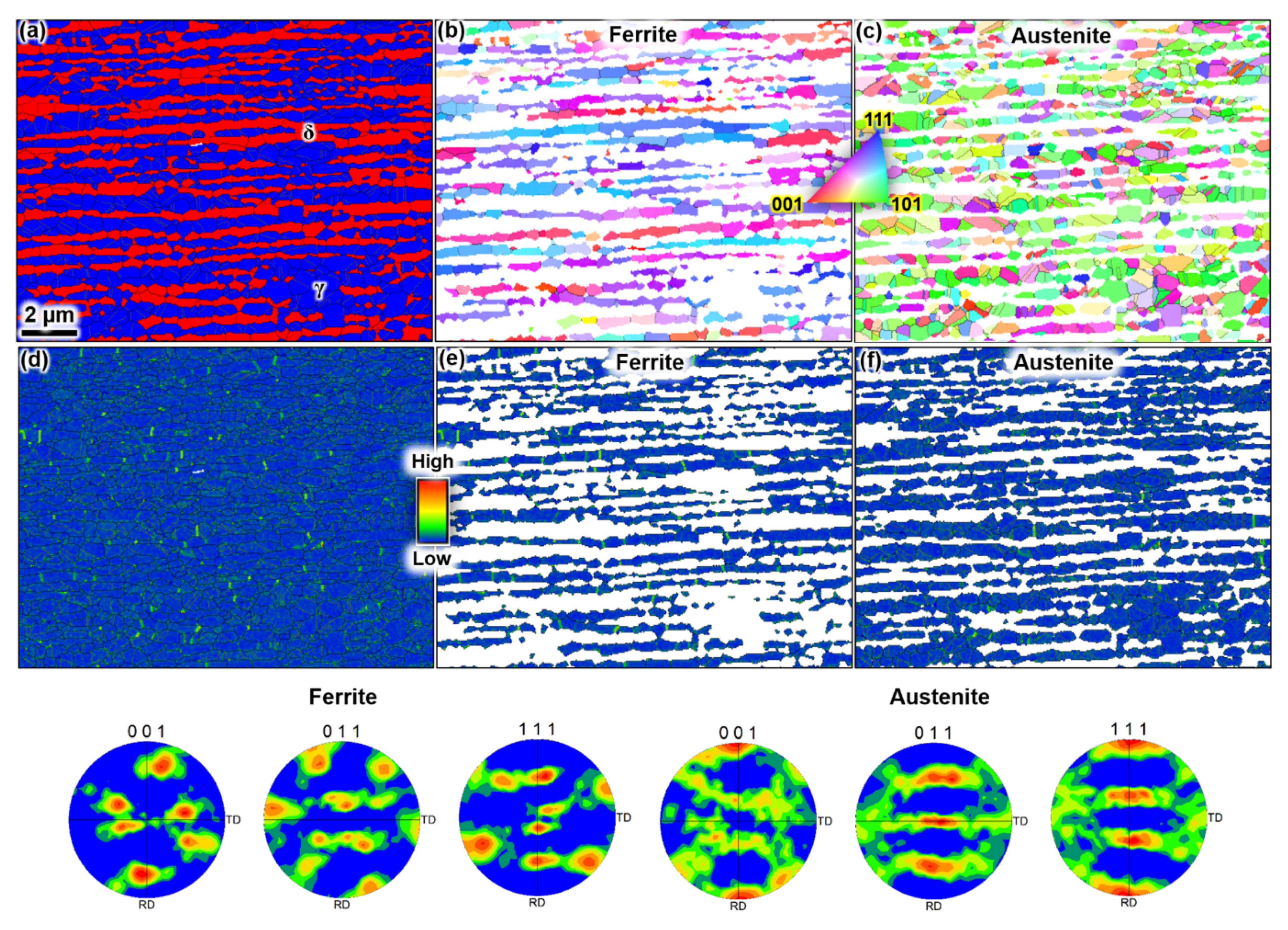
The wire duplex microstructure consisted of an approximate ratio of 50:50 ferrite and austenite, with an average grain size of 1 µm (Figure 1). Extensive local misorientation hot spots were detected on the grain and phase boundaries, indicating stored deformation energy. The ferrite and austenite grains were elongated along the rolling direction. The pole figures and inverse pole figure (IPF) maps in Figure 1 reveal that the main texture components are (111)//normal direction (ND) for the ferrite phase; and (011)//ND for the austenite phase. Those crystallographic textures are typical for deformed and recrystallized face-centred cubic (FCC) and body-centred cubic (BCC) materials. Residual deformation strains existed in both phases, as indicated by the Kernel average misorientation (KAM) maps.
3.2. Polarisation Behaviour
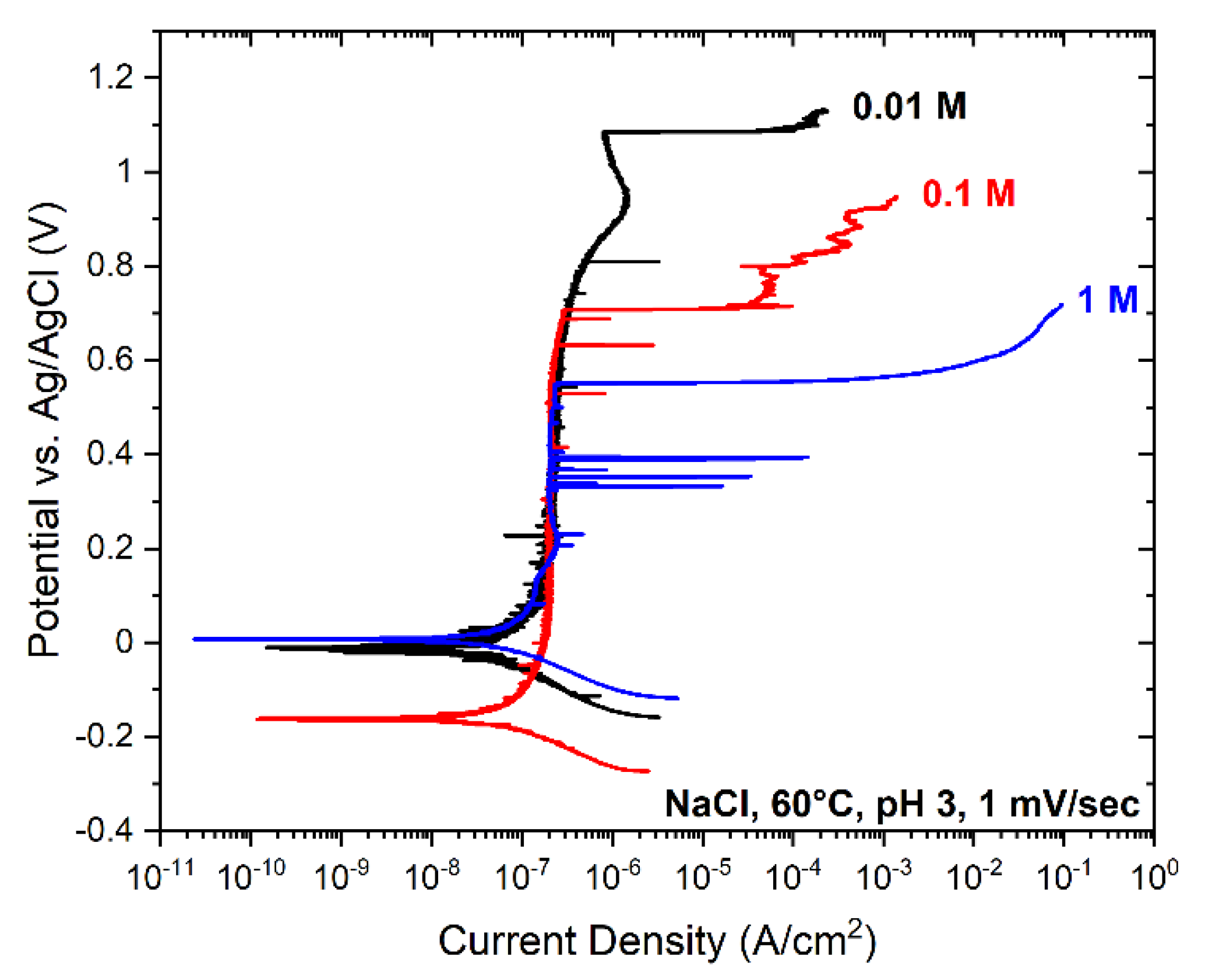
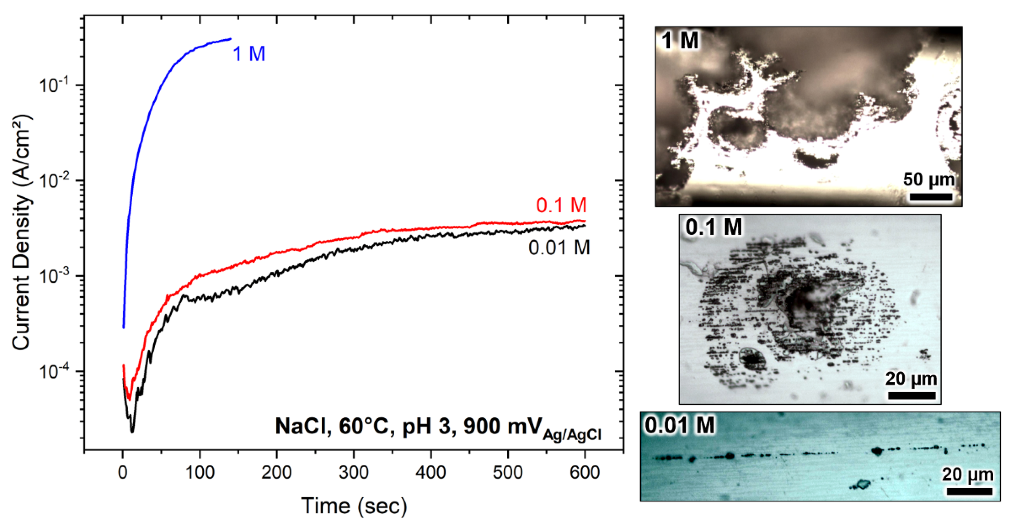
The electrochemical polarisation results performed in 0.01 M, 0.1 M, and 1 M NaCl solutions at pH 3 and 60 °C are summarised in Figure 2. The passive film’s local breakdown potential at 1 M, 0.1 M and 0.01 M solutions was 550 ± 25 mV, 700 ± 25 mV, 1100 ± 25 mV, respectively. The breakdown was facilitated by increasing chloride concentration in line with other reports [2,29,46,47,58]. In all conditions, the steel was spontaneously passive with passive corrosion currents of ~10−7 A/cm2. Grade 2205 duplex stainless steel is immune to pitting at room temperature and only suffers from pitting corrosion above the critical pitting temperature which is 40 °C [59]. Next, the steel was polarised at 900 mV vs. Ag/AgCl under potentiostatic control in the respective chloride solutions. The results are summarised in Figure 3. The currents in 0.01 M and 0.1 M chloride solutions were similar on the order of ~5 × 10⁻² A/cm2, whereas, in 1 M electrolyte, the current was two orders of magnitude higher on the order of ~0.5 A/cm2. In all cases, the currents rapidly rose, reaching high values, resulting in localised corrosion.
3.3. Corrosion Morphology
The corrosion morphologies were characterised under an optical microscope, depicted in Figure 3. From a macroscopic point of view, two distinctive corrosion forms were observed: (i) selective corrosion of the ferrite phase and (ii) large pit formation with perforated covers. The steel formed lacy cover pits in 0.1 M and 1 M solutions, whereas the ferrite’s preferential breakdown was seen in 0.01 M chloride solution, with the austenite remaining mainly passive. The large corrosion pits were far more extensive and progressed to bigger sizes in 1 M NaCl than in 0.1 M NaCl solution. The lacy cover pits were in dimensions on the order of 100–300 µm in diameter. The pit covers in 1 M solution mainly were damaged, but those formed in 0.1 M electrolyte remained primarily intact. The pit dissolution kinetics were more rapid in 1 M solution, leading to metal dissolution with high volumes, apparent from the larger cavity sizes.
The selective corrosion in duplex stainless steel is well-documented [10,11,12,13,14,15,26,27,28,30,37,60,61]. In short, the elemental partitioning of the alloying elements into the austenite and ferrite phases lead to different corrosion and breakdown potentials. The ferrite is often the weaker phase in chloride-bearing acidic and neutral solutions, and it undergoes selective corrosion while the austenite is passive. The ferrite’s breakdown potential is lower than that of the austenite despite the higher chromium content in bulk and passive film [62,63]. The lower electrochemical nobility of the ferrite phase is also manifested by 40–70 mV less noble work functions in the ferrite phase than the austenite phase [15,56]. The reason for the higher electrochemical nobility of the austenite phase is due to high nitrogen content, which is mainly partitioned into the austenite phase.
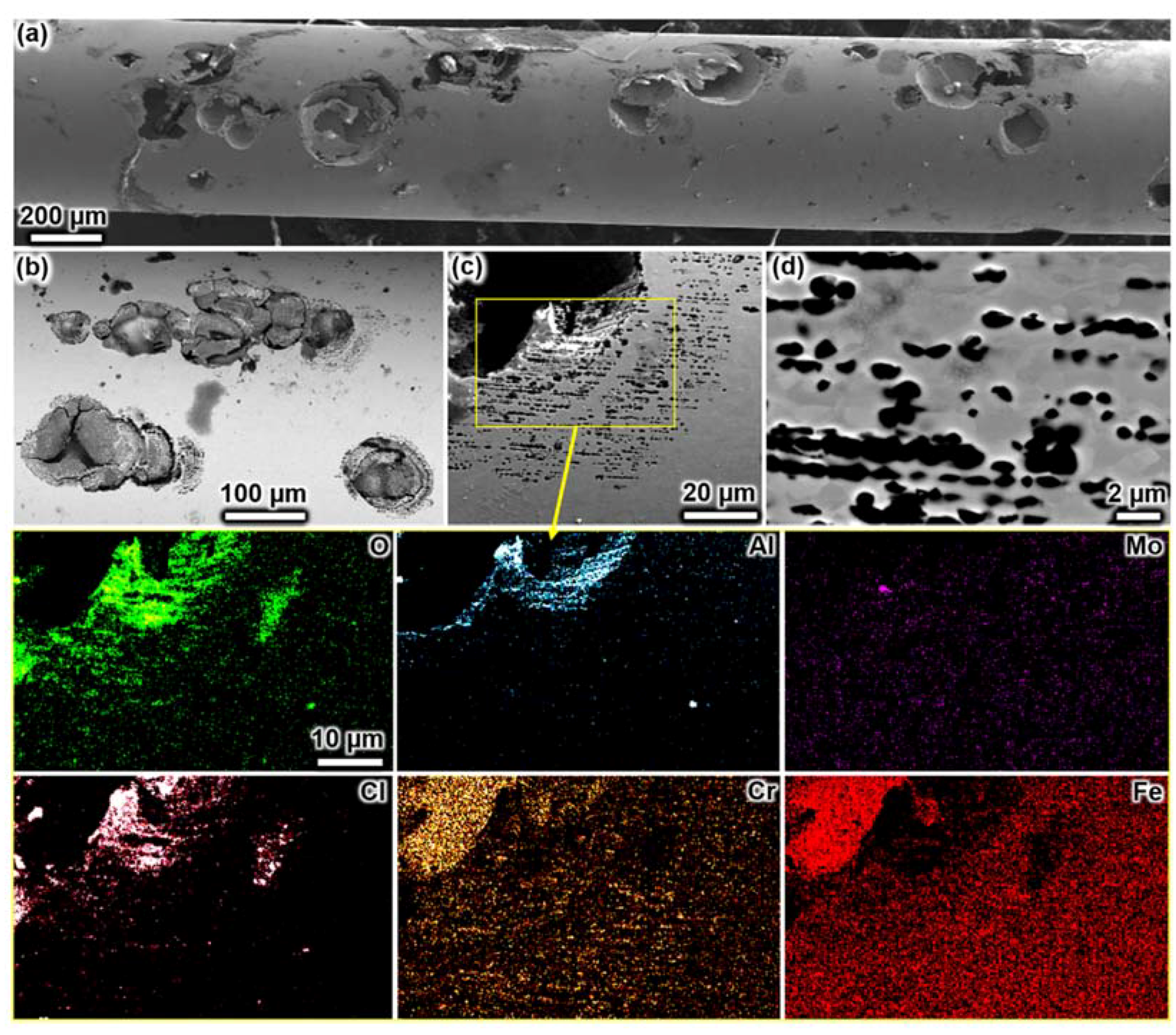
The corrosion morphology after anodic polarisation in 1 M NaCl solution is shown in Figure 4. Large discrete corrosion pits with partially destroyed perforated metal covers (Figure 4a), having cracks on the pit cover, were seen (Figure 4b). EDX mapping was performed over a cover remnant near the pit mouth (Figure 4c), revealing intense aluminium and oxygen signals. Aluminium is an impurity element originating from metallurgical purification processes and is present with silicon in the form of oxide inclusions [64]. It seems that aluminium in the inclusions preferentially oxidised and formed thick anodic oxides on the cover surface. Interestingly, dissolved aluminium seemed to redeposit on the pit cover. Seemingly, the surface anodic oxides’ thickness and composition over the pit cover differed over the entire pit area. The perforation occurred in discrete grains without, however, resulting in the dissolution of an entire grain (Figure 4c). The perforation occurred on both ferrite and austenite grains but seemingly was influenced by the grain alignment along the rolling direction. Our results do not entirely confirm Eguchi et al., who reported pit cover perforation associated with the dissolution of whole ferritic grains of lean 2202 duplex stainless steel [44]. Our interpretation of the SEM micrographs provided in their work is that the corrosion (perforation) occurred on partial grains instead of entire grains, being in line with our observations. However, it should be noted that the chemical composition and grain size of their steel wire are different from what we investigated. So, there might be compositional and grain size effects influencing the pitting behaviour. In line with Eguchi et al. [44], our work shows that the pitting in duplex stainless steel has an undercutting nature independent of the grain size.
The discussion about grain size and orientation is interesting and essential from an application point of view. It is well-known that the work function is a function of grain orientation [65,66,67]. The work function has been reported to decrease with decreasing grain size due to severe drops occurring at grain boundaries due to the highly defective nature [66]. A reduction of the grain size is usually achieved by mechanical deformation of the microstructure, which increases the number of defects (dislocation, low and high angle grain boundaries, stored energy). Therefore, fine microstructures are usually more susceptible to corrosion than coarser ones. The passive film over imperfect microstructural sites is weaker than more regular lattice regions [68]. The passive film composition has been earlier demonstrated to vary depending on the grain orientation in duplex stainless steel [62]. There can be significant compositional variations with up to 20% among ferritic and austenitic grains [62]. Therefore, the corrosion resistance changes with the microstructure and the intensity of chemical heterogeneity in duplex stainless steel.
3.4. Pit Cover Collapse and Hydrogen Embrittlement
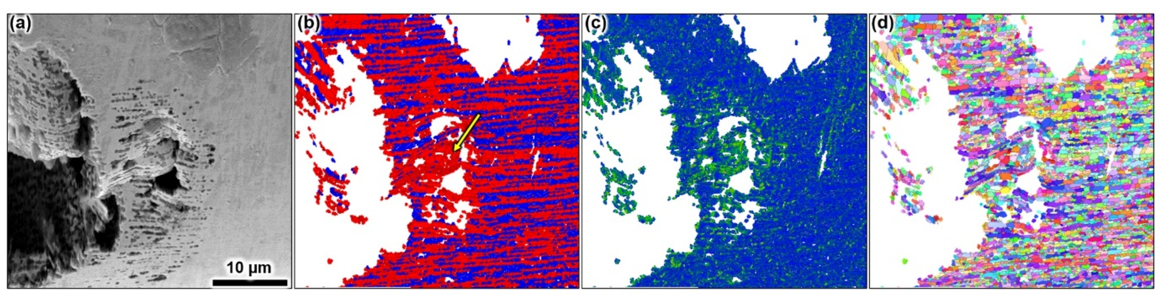
Figure 5a shows a corrosion pit (developed in 1 M solution) with a lacy cover having collapsed partially. We analysed this region with EBSD (Figure 5b–d). The local misorientation map in Figure 5c highlights strain localisation formed on the perforated cover indicating plasticity involved in the cover’s collapse (green colour code in Figure 5c). The phase map in Figure 5b shows a high density of grain boundaries, indicating heavy local plastic deformation. The phase map further indicates a large portion of ferrite around the collapsed region, as pointed by the arrow in Figure 5b, which is unusual for the studied wire microstructure.
The austenite spacing of the studied microstructure is on the order of one to four grains, corresponding to a length of a maximum of 4–5 µm. However, the austenite spacing in the highlighted region is 8–10 µm. There, a lower fraction of austenite grains was detected. The austenite grains in and around the strain hot-spot site are individual and relatively apart from each other compared to regions beyond the pit sites. The crystallographic orientation map in Figure 5d demonstrates severe plastic deformation at and in the vicinity of the collapsed pit cover area. The grains are distorted and became non-isotopically shaped. Hence, the EBSD data points towards strain-induced martensite, with the martensite being indexed as ferrite. The austenite phase is metastable and transforms when high strains far above the yield point are formed [69,70]. The necessary stress to deform austenite grains in the lacy cover can only be explained by hydrogen absorption, resulting in heavy local elastic and elastic-plastic deformation [71,72,73]. Hence, hydrogen evolution must have occurred during pitting corrosion since no other stress evolution source in the pit cover is possible. It is characteristic for pit covers to occlude the corrosion electrolyte within the pit, facilitating acidic chemistries of pH as low as 0 [41,42,74,75]. In acidic solutions, hydrogen evolution dominates the cathodic reduction, which ultimately can be absorbed by the metal. The lacy cover is a maximum of 1–2 grains thick [39]. The surface-to-volume ratio is high, causing a large flux of hydrogen absorption in the austenite, with grain and sub-grain boundaries providing rapid access to the lattice furthermore. Therefore, the pit cover collapse is not a geometric issue but instead occurs due to hydrogen embrittlement. These observations have been made for all lacy cover pits with radii larger than 50 µm on several specimens.
The pits in Figure 4 were on the order of 100 µm in diameter. We assumed hemispherical pit morphology and calculated the metal loss by considering a pit radius of 50 µm. Hence, the metal loss associated with a pit with a 100 µm diameter is 2 ng. With Faraday’s law, the liberated charge was 155 mC, and with 140 sec of potentiostatic control, the electrochemical current was 1.11 mA. Hydrogen evolution in acidic electrolytes occurs via a two-electron transfer. However, monatomic hydrogen is produced first by which adsorbed hydrogen atoms are formed. Approximately 99% of all hydrogen formed dissipates as hydrogen gas, but ≈1% can enter the microstructure. Therefore, the amount produced per liberated charge (n = 2.19) is about 4 mM, corresponding to 400 ppm. Thus, nearly 4 ppm of atomic hydrogen entered the microstructure, causing hydrogen embrittlement to occur. It has been reported that 0.7 ppm is sufficient to cause hydrogen embrittlement of high-strength steel [76]. The duplex wire has a tensile strength of ≈1100 MPa and is susceptible to hydrogen embrittlement [64]. Therefore, the cause of the cracking and collapse of the perforated metal cover over the corrosion pits must have been reasoned by hydrogen embrittlement.
Figure 6a shows a lacy cover pit observed after polarisation in 0.1 M NaCl solution. None of the pit covers collapsed and showed numerous perforations. As observed in the 1 M solution, the holes were not associated with any phase and evolved seemingly in a more stochastic manner on ferrite and austenite grains. Interestingly, the corrosion occurred on sub-grains and showed perforation sites smaller than the average grain size in both phases (Figure 6b,c). It remained unclear why some parts of grains remained passive during the pit evolution. Grains from the ferrite and the austenite phase showed similar behaviour. It seems that the corrosion chemistry was aggressive so that no selective dissolution of any phase occurred. Pit cover formation is, however, influenced by the grain alignment as seen in corrosion in the 1 M NaCl electrolyte.
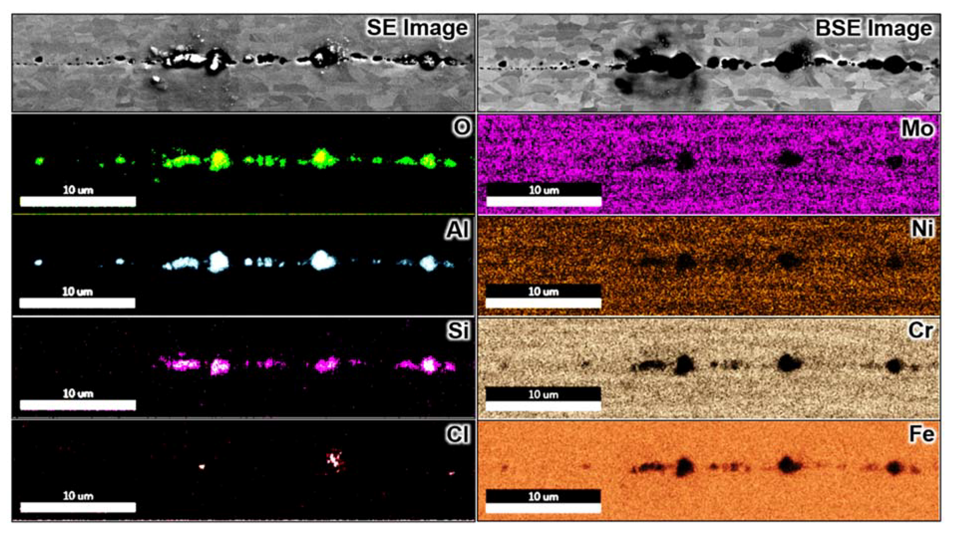
Figure 7 and Figure 8 summarise SEM and EDX analyses performed over the specimen after polarisation in 0.01 M NaCl solution. Here, no macroscopic pit cavity occurred, and only selective corrosion of the ferrite phase was observed, which progressed along the processing direction along the wire. The preferential dissolution front often spanned over the entire exposed wire surface with multiple initiation sites, with numerous densely arrayed pits forming the corrosion front of selective corrosion. The ferrite’s selective dissolution in grade 2205 duplex stainless steel has often been reported [10,15,27,28,30,37,62]. There seemed to be minor corrosion undercutting events on some sites within the selectively corroded ferrite, which spanned over a few grains perpendicular to the processing direction, as noticeable from the backscattered electron signals in Figure 7 and Figure 8, which yield information from the sub-surface. Seemingly, a corrosion pit without a lacy cover was formed during the undercutting process. Selective dissolution is less harmful than metal perforation, which creates corrosion cavities with aggressive local electrolytes. The corrosion sites of the selectively corroded wire were not deep as earlier observed on the same metal subjected to atmospheric corrosion for up to two years [26].
3.5. Selective Corrosion
The corrosion nature of both phases depends not only on the potential differences between the two phases but more on the environment’s corrosivity. The environment dictates the phases’ anodic potentials, and active, passive, and pitting behaviour for both phases in duplex stainless steels has been reported [11,16,27,32]. However, stainless steels are spontaneously passive in most chloride-containing electrolytes without the presence of passivating agents such as sulphates or nitrates, and therefore activation of duplex stainless steel does usually not occur. The oxidising power of most engineering applications (no crevice effects) is not sufficient to activate duplex stainless steel so that only pitting forms. In sulphuric acid environments, duplex stainless steel can be activated, and it has been shown that the active-to-passive behaviour of the ferrite phase occurs 50–100 mV earlier than that of the austenite phase [11,12,13,17]. Therefore, selective corrosion of the ferrite phase in chloride solutions must occur via multiple pitting events, as demonstrated by the SEM micrographs (Figure 4 and Figure 6, Figure 7 and Figure 8). Hence, the ferrite’s selective dissolution proceeded by the numerous formation sites of tiny pits, which laterally coincided (Figure 8). The mechanism of selective dissolution of the ferrite phase is not through its activation, which would cause an ‘etching effect’ of the entire ferrite phase, but is instead via a pitting mechanism. It seems that the corrosion progressed by discrete pit evolution on the ferrite phase and by undercutting events along the ferrite grains along the rolling direction, with both probably coinciding. The corrosion advanced below the surface and demonstrated the propensity for duplex stainless steel to develop undercutting metal dissolution. It seems that lateral growth is more preferred (across the processing direction) than growing towards depth. Hence, lacy cover pits only set if the corrosion electrochemistry is harsh, which occurred in more concentrated electrolytes as described above. The detected corrosion products were mainly aluminium and silicon oxides, stemming from inclusions and were produced within the corrosion front’s anodic sites. Apparently, corrosion was favoured around the inclusions, and interestingly, the inclusions were circumvented in ferritic grains. It is well-known that inclusions form incoherent boundaries with their neighbouring matrix causing preferential corrosion attack via a crevice-like mechanism [77].
3.6. Final Remarks
The pitting corrosion observed in the studied duplex stainless steel wire represents other material types of duplex stainless steel. We also observed lacy cover pitting corrosion in plate and sheet materials. However, the magnitude and propensity of the corrosion are seemingly higher in wire materials than in plates and sheets due to the higher stored energy in the microstructure. Furthermore, lacy cover pits with large dimensions are only possible under immersed conditions. The more common corrosion morphology that may occur in practice is a selective attack on the ferrite phase. The work reported here sheds light on the corrosion mechanism of duplex stainless steel. Above the critical pitting temperature, the chloride concentration determines the corrosion morphology and the severity of the corrosion attack. Hence, selective dissolution is less detrimental than lacy cover pitting. As a result, duplex stainless steels are superior corrosion resistant to single-phase stainless steel with counterpart chemical composition.
4. Conclusions
- The corrosion morphology of duplex stainless steel depends on the electrolyte’s corrosivity, which promotes either the evolution of selective corrosion of usually the ferrite phase or pits with perforated lacy covers.
- Perforated lacy metal pit covers are formed when the electrolyte is aggressive.
- Lacy cover pitting is not favoured when the chloride-ion concentration is below a threshold at which the ferrite phase’s selective dissolution occurs.
- The perforation of lacy pit covers is not associated with either the ferrite or austenite phase.
- Lacy cover pit formation occurs stochastically on grains of both phases but is influenced by the material’s processing orientation.
- The ferrite phase’s selective corrosion occurs by simultaneous pit evolution and undercutting events of a grown pit along the rolling direction.
- The collapse of the lacy pit cover is due to hydrogen embrittlement.
Author Contributions
Conceptualization, C.Ö.; methodology, C.Ö., K.D., A.B. and M.K.; software, K.D., M.K., and A.B.; validation, C.Ö. and M.Ü.; formal analysis, C.Ö., K.D., A.B. and M.K.; investigation, C.Ö., K.D., A.B. and M.K.; resources, C.Ö., K.D. and M.K.; data curation, C.Ö. and M.K.; writing—original draft preparation, C.Ö.; writing—review and editing, C.Ö., K.D., A.B., M.K. and M.Ü.; visualization, C.Ö., K.D., A.B. and M.K.; supervision, M.K.; project administration, C.Ö.; funding acquisition, C.Ö. All authors have read and agreed to the published version of the manuscript.
Funding
This research was funded by TÜBİTAK (The Scientific and Technological Research Council of Turkey) under contract number 118C227 within the program “2232: International Fellowship for Outstanding Researchers”.
Institutional Review Board Statement
Not applicable.
Informed Consent Statement
Not applicable.
Data Availability Statement
The data presented in this study are available on reasonable request from the corresponding author.
Acknowledgments
The authors are grateful to Ugitech SA (France) for providing the duplex stainless steel wire material.
Conflicts of Interest
The authors declare no conflict of interest.
References
- Shibata, T.; Takeyama, T. Stochastic Theory of Pitting Corrosion. Corrosion 1977, 33, 243–251. [Google Scholar] [CrossRef]
- Hospadaruk, V.; Petrocelli, J.V.; Hospadaruk, V.; Petrocelli, J.V. The Pitting Potential of Stainless Steels in Chloride Media. J. Electrochem. Soc. 1966, 113, 878–883. [Google Scholar] [CrossRef]
- Engelhardt, G.R.; Macdonald, D.D. Monte-Carlo Simulation of Pitting Corrosion with a Deterministic Model for Repassivation. J. Electrochem. Soc. 2020, 167, 013540. [Google Scholar] [CrossRef]
- Laycock, N.J.; Krouse, D.P.; Hendy, S.C.; Williams, D.E. Computer Simulation of Pitting Corrosion of Stainless Steels. Electrochem. Soc. Interface 2014, 23, 65–71. [Google Scholar] [CrossRef]
- Valor, A.; Caleyo, F.; Alfonso, L.; Rivas-López, D.; Hallen, J. Stochastic modeling of pitting corrosion: A new model for initiation and growth of multiple corrosion pits. Corros. Sci. 2007, 49, 559–579. [Google Scholar] [CrossRef]
- Jayalakshmi, M.; Muralidharan, V. Empirical and Deterministic Models of Pitting Corrosion—An Overview. Corros. Rev. 1996, 14, 375–402. [Google Scholar] [CrossRef]
- Macdonald, D.D.; Engelhardt, G. Predicting the future from the past in corrosion science and engineering. In Proceedings of the EUROCORR 2004: Long Term Prediction and Modeling of Corrosion, Nice, France, 12–16 September 2004. [Google Scholar]
- Schultze, J.; Lohrengel, M. Stability, reactivity and breakdown of passive films. Problems of recent and future research. Electrochimica Acta 2000, 45, 2499–2513. [Google Scholar] [CrossRef]
- Marcus, P.; Maurice, V. The Structure of Passive Films on Metals and Alloys. In Passivity of Metals and Semiconductors; Ives, M.B., Luo, J.L., Rodda, J.R., Eds.; The Electrochemical Society: Jasper Park Lodge, AB, Canada, 1999; pp. 30–64. [Google Scholar]
- Långberg, M.; Örnek, C.; Evertsson, J.; Harlow, G.S.; Linpé, W.; Rullik, L.; Carlà, F.; Felici, R.; Bettini, E.; Kivisäkk, U.; et al. Redefining passivity breakdown of super duplex stainless steel by electrochemical operando synchrotron near surface X-ray analyses. NPJ Mater. Degrad. 2019, 3, 22. [Google Scholar] [CrossRef]
- Symniotis, E. Galvanic Effects on the Active Dissolution of Duplex Stainless Steels. Corrosion 1990, 46, 2–12. [Google Scholar] [CrossRef]
- Aoki, S.; Ito, K.; Yakuwa, H.; Miyasaka, M.; Sakai, J. Potential Dependence of Preferential Dissolution Behavior of a Duplex Stainless Steel in Simulated Solution inside Crevice. Zairyo-to-Kankyo 2011, 60, 363–367. [Google Scholar] [CrossRef] [Green Version]
- Aoki, S.; Yakuwa, H.; Mitsuhashi, K.; Sakai, J.i. Dissolution Behavior of α and γ Phases of a Duplex Stainless Steel in a Simulated Crevice Solution. ECS Trans. 2010, 25, 17–22. [Google Scholar] [CrossRef]
- Ornek, C.; Walton, J.; Hashimoto, T.; Ladwein, T.L.; Lyon, S.; Engelberg, D. Characterization of 475 °C Embrittlement of Duplex Stainless Steel Microstructure via Scanning Kelvin Probe Force Microscopy and Magnetic Force Microscopy. J. Electrochem. Soc. 2017, 164, C207–C217. [Google Scholar] [CrossRef]
- Örnek, C.; Engelberg, D. SKPFM measured Volta potential correlated with strain localisation in microstructure to understand corrosion susceptibility of cold-rolled grade 2205 duplex stainless steel. Corros. Sci. 2015, 99, 164–171. [Google Scholar] [CrossRef]
- Tsai, W.-T.; Chen, J.-R. Galvanic corrosion between the constituent phases in duplex stainless steel. Corros. Sci. 2007, 49, 3659–3668. [Google Scholar] [CrossRef]
- Lee, J.-S.; Fushimi, K.; Nakanishi, T.; Hasegawa, Y.; Park, Y.-S. Corrosion behaviour of ferrite and austenite phases on super duplex stainless steel in a modified green-death solution. Corros. Sci. 2014, 89, 111–117. [Google Scholar] [CrossRef]
- Eckstein, H.-J. Korrosionsbeständige Stähle; Deutscher Verlag für Grundstoffindustrie GmbH: Leipzig, Germany, 1990. [Google Scholar]
- Bettini, E.; Kivisäkk, U.; Leygraf, C.; Pan, J. Study of corrosion behavior of a 22% Cr duplex stainless steel: Influence of nano-sized chromium nitrides and exposure temperature. Electrochim. Acta 2013, 113, 280–289. [Google Scholar] [CrossRef] [Green Version]
- Bettini, E.; Eriksson, T.; Boström, M.; Leygraf, C.; Pan, J. Influence of metal carbides on dissolution behavior of biomedical CoCrMo alloy: SEM, TEM and AFM studies. Electrochim. Acta 2011, 56, 9413–9419. [Google Scholar] [CrossRef]
- Sathirachinda, N.; Pettersson, R.; Wessman, S.; Kivisäkk, U.; Pan, J. Scanning Kelvin probe force microscopy study of chromium nitrides in 2507 super duplex stainless steel—Implications and limitations. Electrochim. Acta 2011, 56, 1792–1798. [Google Scholar] [CrossRef]
- Sathirachinda, N.; Pettersson, R.; Wessman, S.; Pan, J. Study of nobility of chromium nitrides in isothermally aged duplex stainless steels by using SKPFM and SEM/EDS. Corros. Sci. 2010, 52, 179–186. [Google Scholar] [CrossRef]
- Sathirachinda, N.; Pettersson, R.; Pan, J. Depletion effects at phase boundaries in 2205 duplex stainless steel characterized with SKPFM and TEM/EDS. Corros. Sci. 2009, 51, 1850–1860. [Google Scholar] [CrossRef]
- Sathirachinda, N.; Gubner, R.; Pan, J.; Kivisaäkk, U. Characterization of Phases in Duplex Stainless Steel by Magnetic Force Microscopy/Scanning Kelvin Probe Force Microscopy. Electrochem. Solid-State Lett. 2008, 11, C41–C45. [Google Scholar] [CrossRef]
- Örnek, C.; Engelberg, D.L. Correlative EBSD and SKPFM characterisation of microstructure development to assist determination of corrosion propensity in grade 2205 duplex stainless steel. J. Mater. Sci. 2016, 51, 1931–1948. [Google Scholar] [CrossRef]
- Örnek, C.; Léonard, F.; McDonald, S.A.; Prajapati, A.; Withers, P.J.; Engelberg, D. Time-dependent in situ measurement of atmospheric corrosion rates of duplex stainless steel wires. NPJ Mater. Degrad. 2018, 2, 10. [Google Scholar] [CrossRef] [Green Version]
- Oernek, C.; Zhong, X.; Engelberg, D. Low-Temperature Environmentally Assisted Cracking of Grade 2205 Duplex Stainless Steel Beneath a MgCl2:FeCl3Salt Droplet. Corrosion 2016, 72, 384–399. [Google Scholar] [CrossRef] [Green Version]
- Örnek, C.; Engelberg, D. Towards understanding the effect of deformation mode on stress corrosion cracking susceptibility of grade 2205 duplex stainless steel. Mater. Sci. Eng. A 2016, 666, 269–279. [Google Scholar] [CrossRef]
- Pettersson, R.; Johansson, M.; Westin, E.M. Corrosion Performance of Welds in Duplex, Superduplex and Lean Duplex Stainless Steels. In CORROSION 2013; NACE International: Houston, TX, USA, 2013. [Google Scholar]
- Örnek, C.; Idris, S.A.; Reccagni, P.; Engelberg, D.L. Atmospheric-Induced Stress Corrosion Cracking of Grade 2205 Duplex Stainless Steel—Effects of 475 °C Embrittlement and Process Orientation. Metals 2016, 6, 167. [Google Scholar] [CrossRef] [Green Version]
- Pettersson, R.F.A.; Flyg, J. Electrochemical Evaluation of Pitting and Crevice Corrosion Resistance of Stainless Steels in NaCl and NaBr; Outokumpu: Stockholm, Sweden, 2004. [Google Scholar]
- Ritter, J. The Application of Duplex Stainless Steels in Different Media. In Surface and Materials Engineering, Corrosion Laboratory; Aalen University of Applied Sciences: Aalen, Germany, 2013. [Google Scholar]
- Oldfield, J.W.; Todd, B. Room temperature stress corrosion cracking of stainless steels in indoor swimming pool atmospheres. Br. Corros. J. 1991, 26, 173–182. [Google Scholar] [CrossRef]
- Oldfield, D.J.W. Nickel effect: Lower rate of corrosion in stainless. Emerald Group Publ. Ltd. 1990, 37, 9–11. [Google Scholar] [CrossRef]
- Lu, Y.; Ives, M.; Clayton, C. Synergism of alloying elements and pitting corrosion resistance of stainless steels. Corros. Sci. 1993, 35, 89–96. [Google Scholar] [CrossRef]
- Nilsson, J.-O.; Chai, G. The physical metallurgy of duplex stainless steels. In Proceedings of the International Conference & Expo Duplex 2007, Associazone Italiana di Metallurgia (AIM), Grado, Italy, 18–20 June 2007. [Google Scholar]
- Örnek, C.; Engelberg, D. An experimental investigation into strain and stress partitioning of duplex stainless steel using digital image correlation, X-ray diffraction and scanning Kelvin probe force microscopy. J. Strain Anal. Eng. Des. 2016, 51, 207–219. [Google Scholar] [CrossRef] [Green Version]
- Örnek, C.; Burke, M.G.; Hashimoto, T.; Lim, J.J.H.; Engelberg, D.L. 475 °C Embrittlement of Duplex Stainless Steel—A Comprehensive Microstructure Characterization Study. Mater. Perform. Charact. 2017, 6, 409–436. [Google Scholar] [CrossRef]
- Ghahari, S.M.; Davenport, A.J.; Rayment, T.; Suter, T.; Tinnes, J.-P.; Padovani, C.; Hammons, J.A.; Stampanoni, M.; Marone, F.; Mokso, R. In situ synchrotron X-ray micro-tomography study of pitting corrosion in stainless steel. Corros. Sci. 2011, 53, 2684–2687. [Google Scholar] [CrossRef]
- Ghahari, S.M.; Krouse, D.P.; Laycock, N.J.; Rayment, T.; Padovani, C.; Suter, T.; Mokso, R.; Marone, F.; Stampanoni, M.; Monir, M.; et al. Pitting corrosion of stainless steel: Measuring and modelling pit propagation in support of damage prediction for radioactive waste containers. Corros. Eng. Sci. Technol. 2011, 46, 205–211. [Google Scholar] [CrossRef]
- Ernst, P.; Newman, R. Pit growth studies in stainless steel foils. II. Effect of temperature, chloride concentration and sulphate addition. Corros. Sci. 2002, 44, 943–954. [Google Scholar] [CrossRef]
- Ernst, P.; Laycock, N.; Moayed, M.; Newman, R. The mechanism of lacy cover formation in pitting. Corros. Sci. 1997, 39, 1133–1136. [Google Scholar] [CrossRef]
- Laycock, N.; Newman, R. The Use of Pitting Transients to Test Microscopic Models of Localized Corrosion. Mater. Sci. Forum 1995, 192-194, 649–662. [Google Scholar] [CrossRef]
- Eguchi, K.; Burnett, T.L.; Engelberg, D. X-Ray tomographic characterisation of pitting corrosion in lean duplex stainless steel. Corros. Sci. 2020, 165, 108406. [Google Scholar] [CrossRef]
- Burnett, T.L.; McDonald, S.A.; Gholinia, A.; Geurts, R.; Janus, M.; Slater, T.; Haigh, S.J.; Ornek, C.; Almuaili, F.; Engelberg, D.L.; et al. Correlative Tomography. Sci. Rep. 2014, 4, 4711. [Google Scholar] [CrossRef] [Green Version]
- Peguet, L.; Gaugain, A. Localized corrosion resistance of duplex stainless steels: Methodology and properties; a review paper. Revue Métallurgie 2011, 108, 231–243. [Google Scholar] [CrossRef]
- Dong, C.; Luo, H.; Xiao, K.; Sun, T.; Liu, Q.; Li, X. Effect of temperature and Cl− concentration on pitting of 2205 duplex stainless steel. J. Wuhan Univ. Technol. Sci. Ed. 2011, 26, 641–647. [Google Scholar] [CrossRef]
- Jae-Ho, S.; Jae-Bong, L. Critical Pitting Temperature of 2205 Duplex Stainless Steels Using Immersion and Electrochemical Polarization Test Methods. J. Korean Inst. Surf. Eng. 2006, 39, 18–24. [Google Scholar]
- Huang, T.-S.; Tsai, W.-T.; Pan, S.-J.; Chang, K.-C. Pitting corrosion behaviour of 2101 duplex stainless steel in chloride solutions. Corros. Eng. Sci. Technol. 2018, 53, 9–15. [Google Scholar] [CrossRef] [Green Version]
- Lothongkum, G.; Wongpanya, P.; Morito, S.; Furuhara, T.; Maki, T. Effect of nitrogen on corrosion behavior of 28Cr–7Ni duplex and microduplex stainless steels in air-saturated 3.5 wt% NaCl solution. Corros. Sci. 2006, 48, 137–153. [Google Scholar] [CrossRef]
- Prawoto, Y.; Ibrahim, K.M.; Nik, W.S.W. Effect of pH and chloride concentration on the corrosion of duplex stainless steel. Arab. J. Sci. Eng. 2009, 34, 115. [Google Scholar]
- Pettersson, R.; Johansson, E. Stress corrosion resistance of duplex grades. In Duplex World 2010; Charles, J., Ed.; Duplex Stailess Steel World: Beaunne, France, 2010. [Google Scholar]
- Bhattacharya, A.; Singh, P.M. Role of Microstructure on the Corrosion Susceptibility of UNS S32101 Duplex Stainless Steel. Corrosion 2008, 64, 532–540. [Google Scholar] [CrossRef]
- Liljas, M.; Johansson, P.; Liu, H.-P.; Olsson, C.-O.A. Development of a Lean Duplex Stainless Steel. Steel Res. Int. 2008, 79, 466–473. [Google Scholar] [CrossRef]
- Al-Hashem, A.; Caceres, P.G.; Abdullah, A.; Shalaby, H.M. Cavitation Corrosion of Duplex Stainless Steel in Seawater. Corrosion 1997, 53, 103–113. [Google Scholar] [CrossRef]
- Örnek, C.; Leygraf, C.; Pan, J. Passive film characterisation of duplex stainless steel using scanning Kelvin probe force microscopy in combination with electrochemical measurements. NPJ Mater. Degrad. 2019, 3, 8. [Google Scholar] [CrossRef] [Green Version]
- Bunge, H.-J. Texture Analysis in Materials Science: Mathematical Methods; Butterworth & Co.: Göttingen, Germany, 1982. [Google Scholar]
- Frankel, G.S. Pitting Corrosion of Metals: A Review of the Critical Factors. J. Electrochem. Soc. 1998, 145, 2186–2198. [Google Scholar] [CrossRef]
- Örnek, C.; Engelberg, D.L. Effect of “475 °C Embrittlement” on the Corrosion Behaviour of Grade 2205 Duplex Stainless Steel Investigated Using Local Probing Techniques. In Corrosion Management; The Institute of Corrosion: Northampton, UK, 2013; pp. 9–11. [Google Scholar]
- Moura, V.; Lima, L.; Pardal, J.M.; Kina, A.; Corte, R.; Tavares, S. Influence of microstructure on the corrosion resistance of the duplex stainless steel UNS S31803. Mater. Charact. 2008, 59, 1127–1132. [Google Scholar] [CrossRef]
- Nascimento, A.D.; Ierardi, M.; Kina, A.; Tavares, S. Pitting corrosion resistance of cast duplex stainless steels in 3.5%NaCl solution. Mater. Charact. 2008, 59, 1736–1740. [Google Scholar] [CrossRef]
- Långberg, M.; Zhang, F.; Grånäs, E.; Örnek, C.; Cheng, J.; Liu, M.; Wiemann, C.; Gloskovskii, A.; Keller, T.; Schlueter, C.; et al. Lateral variation of the native passive film on super duplex stainless steel resolved by synchrotron hard X-ray photoelectron emission microscopy. Corros. Sci. 2020, 174, 108841. [Google Scholar] [CrossRef]
- Långberg, M.; Örnek, C.; Zhang, F.; Cheng, J.; Liu, M.; Grånäs, E.; Wiemann, C.; Gloskovskii, A.; Matveyev, Y.; Kulkarni, S.; et al. Characterization of Native Oxide and Passive Film on Austenite/Ferrite Phases of Duplex Stainless Steel Using Synchrotron HAXPEEM. J. Electrochem. Soc. 2019, 166, C3336–C3340. [Google Scholar] [CrossRef]
- Eguchi, K.; Burnett, T.L.; Engelberg, D.L. X-ray tomographic observation of environmental assisted cracking in heat-treated lean duplex stainless steel. Corros. Sci. 2021, 184, 109363. [Google Scholar] [CrossRef]
- Li, W.; Li, D. Effect of surface geometrical configurations induced by microcracks on the electron work function. Acta Mater. 2005, 53, 3871–3878. [Google Scholar] [CrossRef]
- Li, W.; Li, D.Y. Effect of Grain Size on the Electron Work Function of Cu and Al. Surf. Rev. Lett. 2004, 11, 173–178. [Google Scholar] [CrossRef]
- Jin, Y.; Liu, M.; Zhang, C.; Leygraf, C.; Wen, L.; Pan, J. First-Principle Calculation of Volta Potential of Intermetallic Particles in Aluminum Alloys and Practical Implications. J. Electrochem. Soc. 2017, 164, C465–C473. [Google Scholar] [CrossRef]
- Nazarov, A.; Thierry, D. Application of Volta potential mapping to determine metal surface defects. Electrochim. Acta 2007, 52, 7689–7696. [Google Scholar] [CrossRef]
- Tsay, L.W.; Young, M.C.; Shin, C.-S.; Chan, S. Hydrogen-enhanced cracking of 2205 duplex stainless steel. Fatigue Fract. Eng. Mater. Struct. 2007, 30, 1228–1236. [Google Scholar] [CrossRef]
- Perdahcıoğlu, E.; Geijselaers, H.; Groen, M. Influence of plastic strain on deformation-induced martensitic transformations. Scr. Mater. 2008, 58, 947–950. [Google Scholar] [CrossRef]
- Örnek, C.; Müller, T.; Kivisäkk, U.; Zhang, F.; Långberg, M.; Lienert, U.; Hwang, K.-H.; Lundgren, E.; Pan, J. Operando time- and space-resolved high-energy X-ray diffraction measurement to understand hydrogen-microstructure interactions in duplex stainless steel. Corros. Sci. 2020, 175, 108899. [Google Scholar] [CrossRef]
- Örnek, C.; Larsson, A.; Harlow, G.S.; Zhang, F.; Kroll, R.; Carlà, F.; Hussain, H.; Kivisäkk, U.; Engelberg, D.L.; Lundgren, E.; et al. Time-resolved grazing-incidence X-ray diffraction measurement to understand the effect of hydrogen on surface strain development in super duplex stainless steel. Scr. Mater. 2020, 187, 63–67. [Google Scholar] [CrossRef]
- Örnek, C.; Larsson, A.; Harlow, G.S.; Zhang, F.; Kroll, R.; Carlà, F.; Hussain, H.; Kivisäkk, U.; Engelberg, D.L.; Lundgren, E.; et al. Metastable Precursor Structures in Hydrogen-infused Super Duplex Stainless Steel Microstructure—An Operando Diffraction Experiment. Corros. Sci. 2020, 176, 109021. [Google Scholar] [CrossRef]
- Ernst, P.; Newman, R. Explanation of the effect of high chloride concentration on the critical pitting temperature of stainless steel. Corros. Sci. 2007, 49, 3705–3715. [Google Scholar] [CrossRef]
- Newman, R.C. W.R. Whitney Award Lecture:Understanding the Corrosion of Stainless Steel. Corrosion 2001, 57, 1030–1041. [Google Scholar] [CrossRef]
- Trautmann, A.; Mori, G.; Oberndorfer, M.; Bauer, S.; Holzer, C.; Dittmann, C. Hydrogen Uptake and Embrittlement of Carbon Steels in Various Environments. Materials 2020, 13, 3604. [Google Scholar] [CrossRef]
- Jeon, S.-H.; Kim, S.-T.; Lee, I.-S.; Park, J.-H.; Kim, K.-T.; Kim, J.-S.; Park, Y.-S. Effects of copper addition on the formation of inclusions and the resistance to pitting corrosion of high performance duplex stainless steels. Corros. Sci. 2011, 53, 1408–1416. [Google Scholar] [CrossRef]
Figure 1.
EBSD analysis results showing (a) the phase distribution of ferrite (red) and austenite (blue) grains, (b) the grain orientations (IPF map) for the ferrite phase, (c) the grain orientations (IPF map) for the austenite phase, (d) local misorientation distribution (Kernel average) of the entire microstructure and (e) for the ferrite phase and (f) for the austenite phase. The pole figures in the bottom show the crystallographic texture of ferrite and austenite grains, with the colour contours showing the strength of the texture.

Figure 2.
Potentiodynamic polarisation (1 mV/s) in NaCl solutions at pH 3 and 60 °C.

Figure 3.
Potentiostatic polarisation in NaCl solutions at 60 °C, pH 3, and 900 mV vs. Ag/AgCl. The micrographs show the representative corrosion morphology after the polarisation measurement.
Figure 3.
Potentiostatic polarisation in NaCl solutions at 60 °C, pH 3, and 900 mV vs. Ag/AgCl. The micrographs show the representative corrosion morphology after the polarisation measurement.

Figure 4.
SEM images showing the corrosion morphology after potentiostatic polarisation in 1 M NaCl at 900 mV vs. Ag/AgCl at pH 3 and 60 °C (see Figure 3). The sample underwent extensive pitting corrosion. The micrograph in (a) shows numerous corrosion pits with partially collapsed lacy covers (SE image), (b) magnified view (BSE image), (c) zoomed view near the pit mouth on a perforated cover remnant, (d) magnified view of the perforated cover. The chemical maps depict the detected elements in the highlighted region in (c).

Figure 5.
SEM/EBSD analysis over a corrosion pit formed after potentiostatic polarisation at 900 mV vs. Ag/AgCl in 1 M NaCl solution at pH 3 and 60 °C. The pit shows a partially collapsed perforated lacy cover. The micrograph in (a) is the BSE image, (b) the corresponding EBSD phase map with ferrite (red) and austenite (blue), (c) the corresponding local misorientation map showing strain localisation (green), and (d) shows the corresponding grain orientations. The scale bar in (a) applies to all images.

Figure 6.
SEM analysis after potentiostatic polarisation in 0.1 M NaCl solution at 900 mV vs. Ag/AgCl at pH 3 and 60 °C. The SE image in (a) shows a perforated pit with a non-collapsed pit cover. The SE image in (b) provides a magnified view on the perforation. The image in (c) shows the same region with BSE signals. The perforation occurred on grains of both phases by a partial attack. The scale bar in (b) also applies to (c).

Figure 7.
SEM and EDX analysis over a selectively corroded region after potentiostatic polarisation in 0.01 M NaCl at 900 mV vs. Ag/AgCl at pH 3 and 60 °C. The ferrite phase underwent selective corrosion. Corrosion products (Al-Si-N-O) were formed along the corroded ferrite grains indicating selective dissolution of Al, Si, and N. Some minor undercutting dissolutions are also seen, showing fewer signals for Fe, Cr, Ni, and Mo. The rolling direction is directed to the horizontal axis of the images. The scale bar in the SE image applies to all images.

Figure 8.
SEM and EDX analysis over a selectively corroded region after potentiostatic polarisation in 0.01 M NaCl at 900 mV vs. Ag/AgCl at pH 3 and 60 °C. The images show that selective corrosion of the ferrite phase proceeded by the initiation of individual corrosion pits along the rolling direction (horizontal axis of the images). The scale bar in the chemical maps also applies to the SEM images.

Publisher’s Note: MDPI stays neutral with regard to jurisdictional claims in published maps and institutional affiliations. |
© 2021 by the authors. Licensee MDPI, Basel, Switzerland. This article is an open access article distributed under the terms and conditions of the Creative Commons Attribution (CC BY) license (https://creativecommons.org/licenses/by/4.0/).
Share and Cite
MDPI and ACS Style
Örnek, C.; Davut, K.; Kocabaş, M.; Bayatlı, A.; Ürgen, M. Understanding Corrosion Morphology of Duplex Stainless Steel Wire in Chloride Electrolyte. Corros. Mater. Degrad. 2021, 2, 397-411. https://doi.org/10.3390/cmd2030021
AMA Style
Örnek C, Davut K, Kocabaş M, Bayatlı A, Ürgen M. Understanding Corrosion Morphology of Duplex Stainless Steel Wire in Chloride Electrolyte. Corrosion and Materials Degradation. 2021; 2(3):397-411. https://doi.org/10.3390/cmd2030021
Chicago/Turabian StyleÖrnek, Cem, Kemal Davut, Mustafa Kocabaş, Aleyna Bayatlı, and Mustafa Ürgen. 2021. "Understanding Corrosion Morphology of Duplex Stainless Steel Wire in Chloride Electrolyte" Corrosion and Materials Degradation 2, no. 3: 397-411. https://doi.org/10.3390/cmd2030021