
Third-Order Sliding Mode Applied to the Direct Field-Oriented Control of the Asynchronous Generator for Variable-Speed Contra-Rotating Wind Turbine Generation Systems


Abstract
:1. Introduction
- -
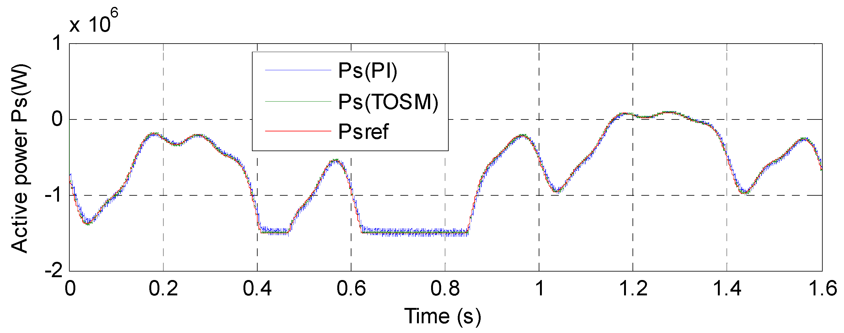
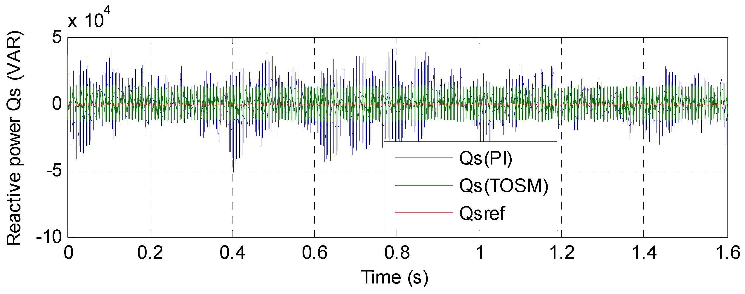
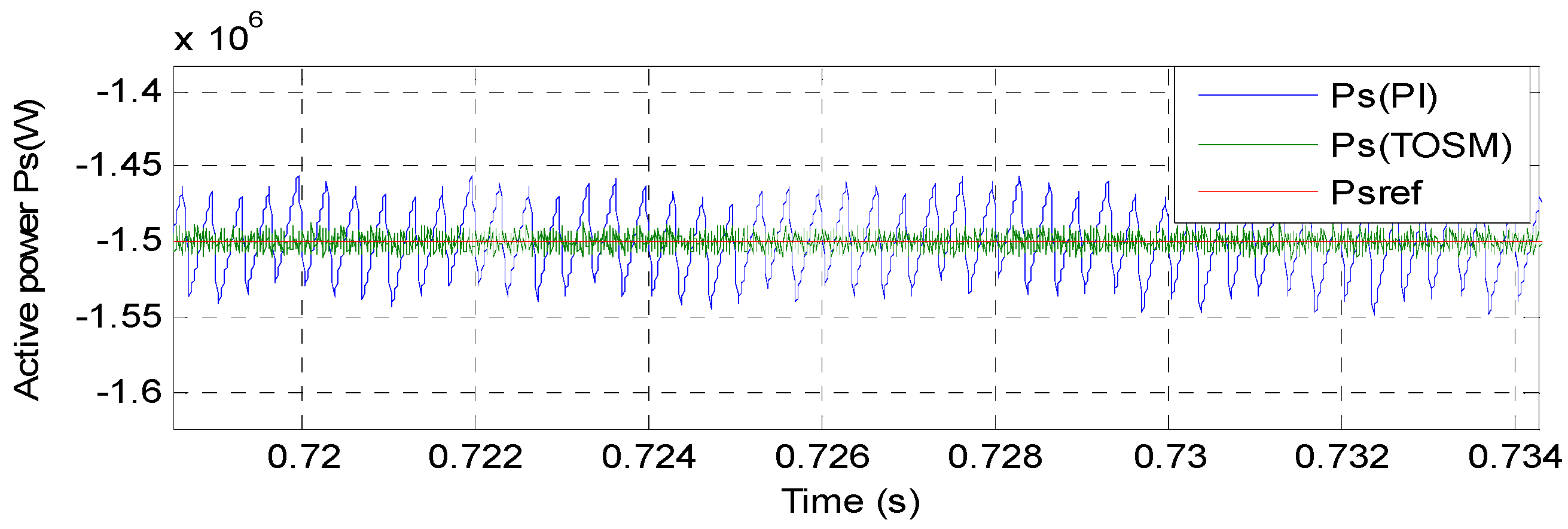
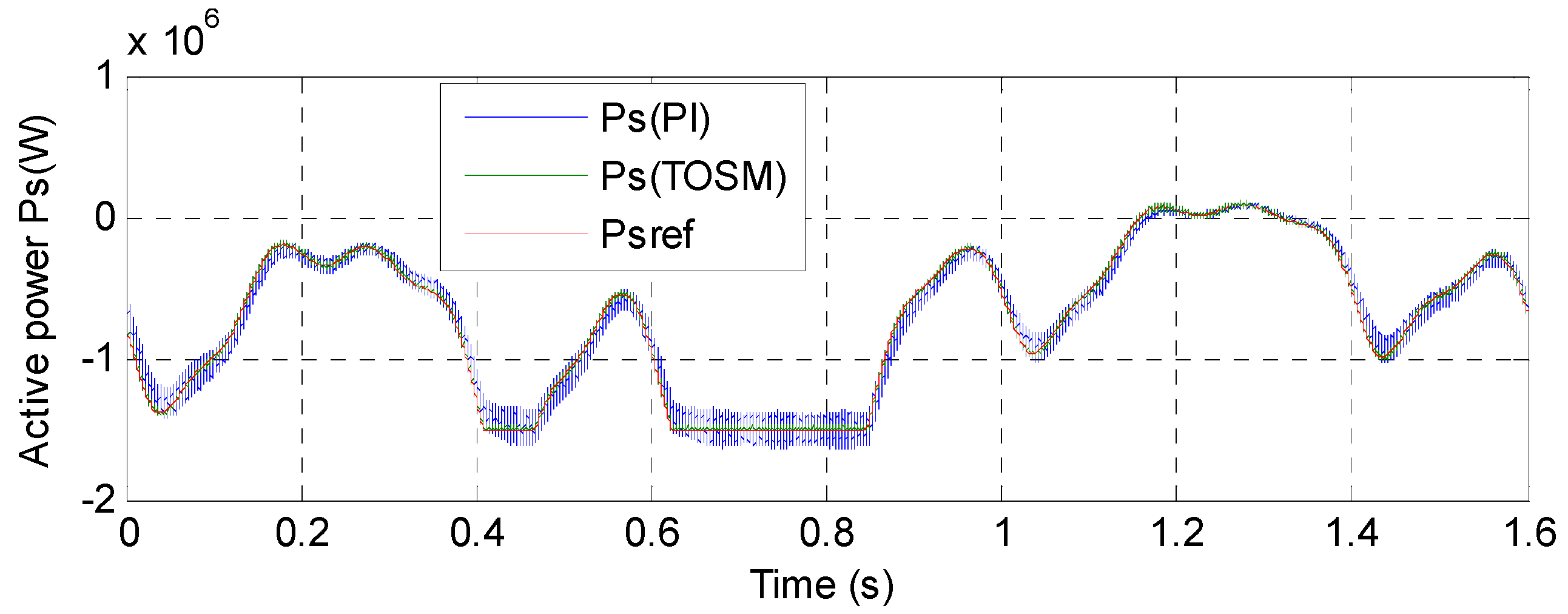
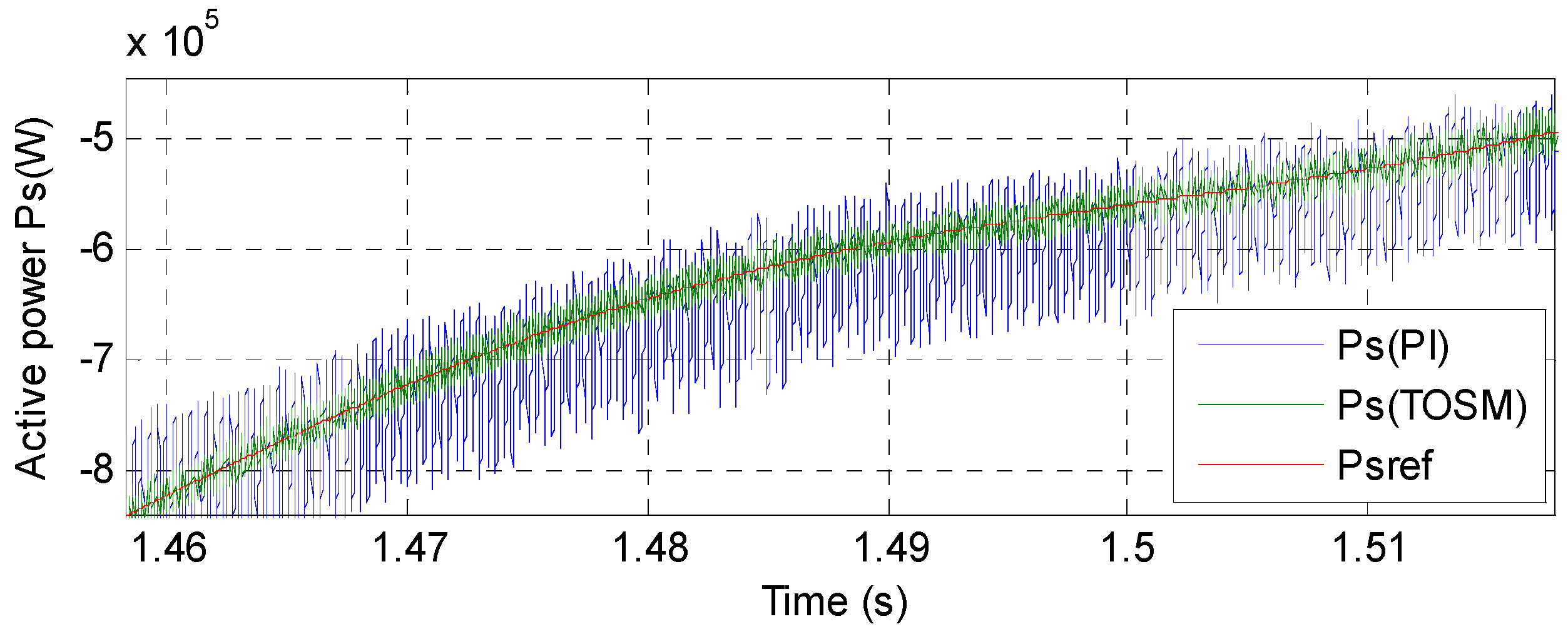
- A new TOSM controller based on the DFOC control scheme is proposed to reduce ripples of both reactive and active powers.
- -
- TOSM controllers minimize the tracking error for reactive and active powers towards the references of ASG-based variable speed CRWP systems.
- -
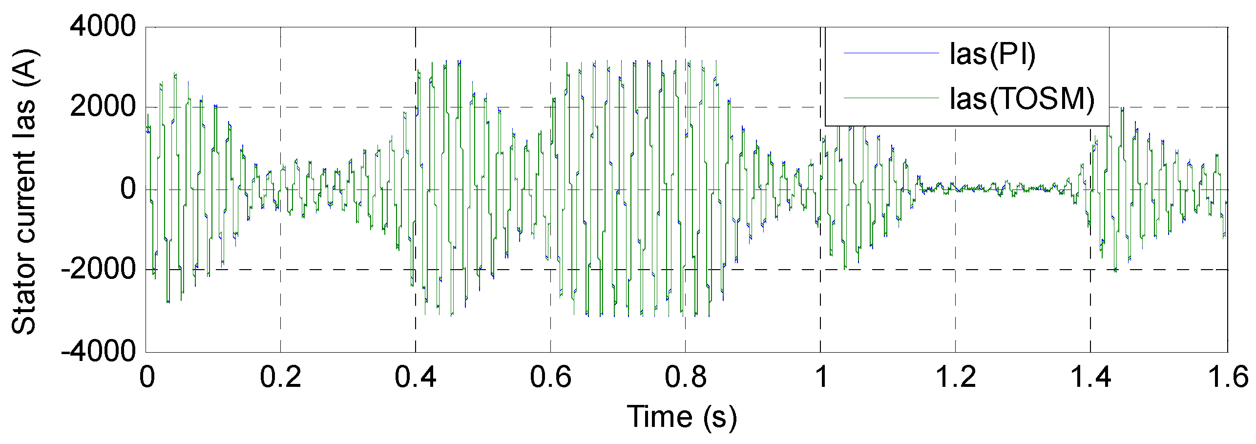
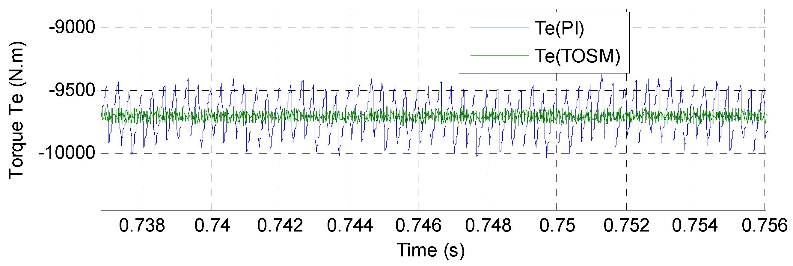
- The DFOC-TOSM control scheme with the PWM technique minimizes the THD value of torque, voltage, and active power of ASG-based variable speed CRWP.
2. CRWP Model
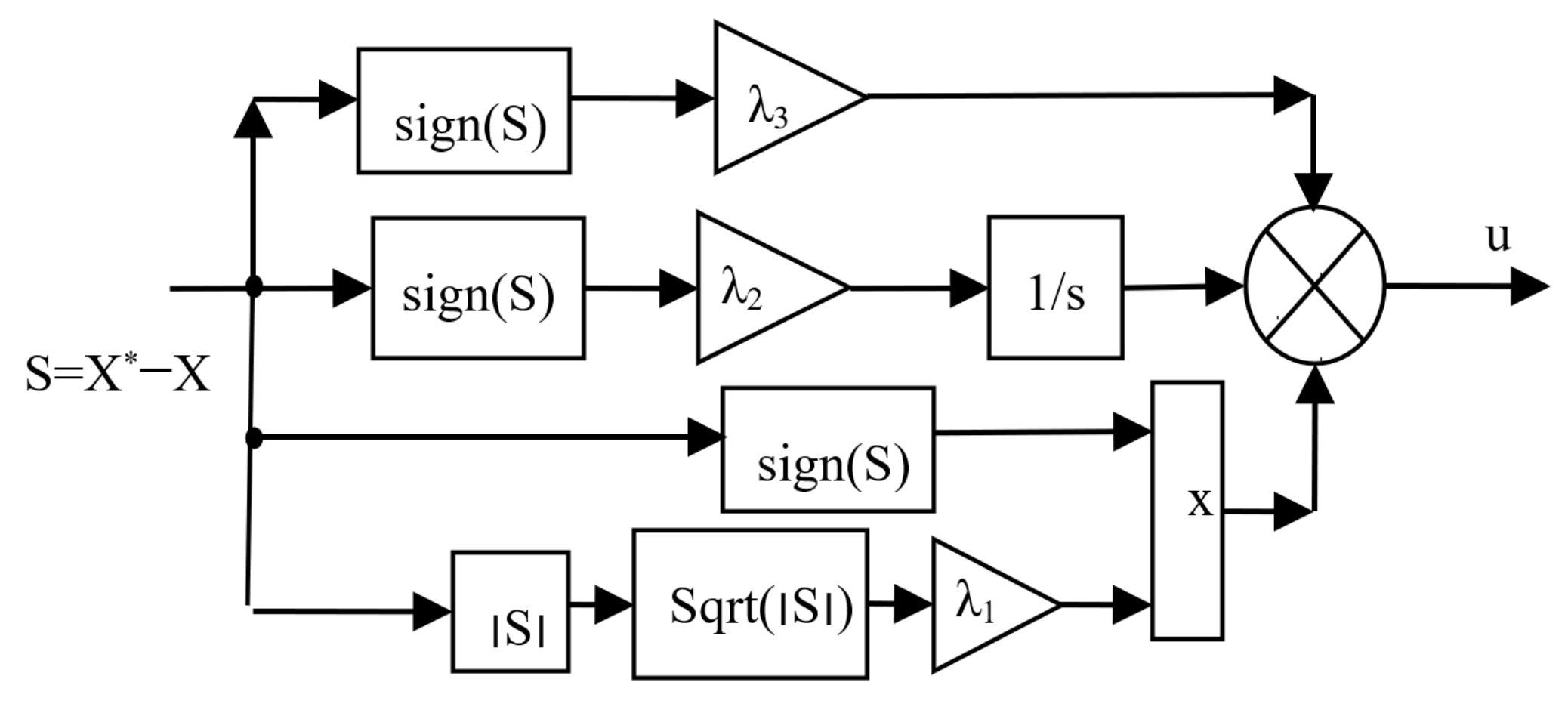
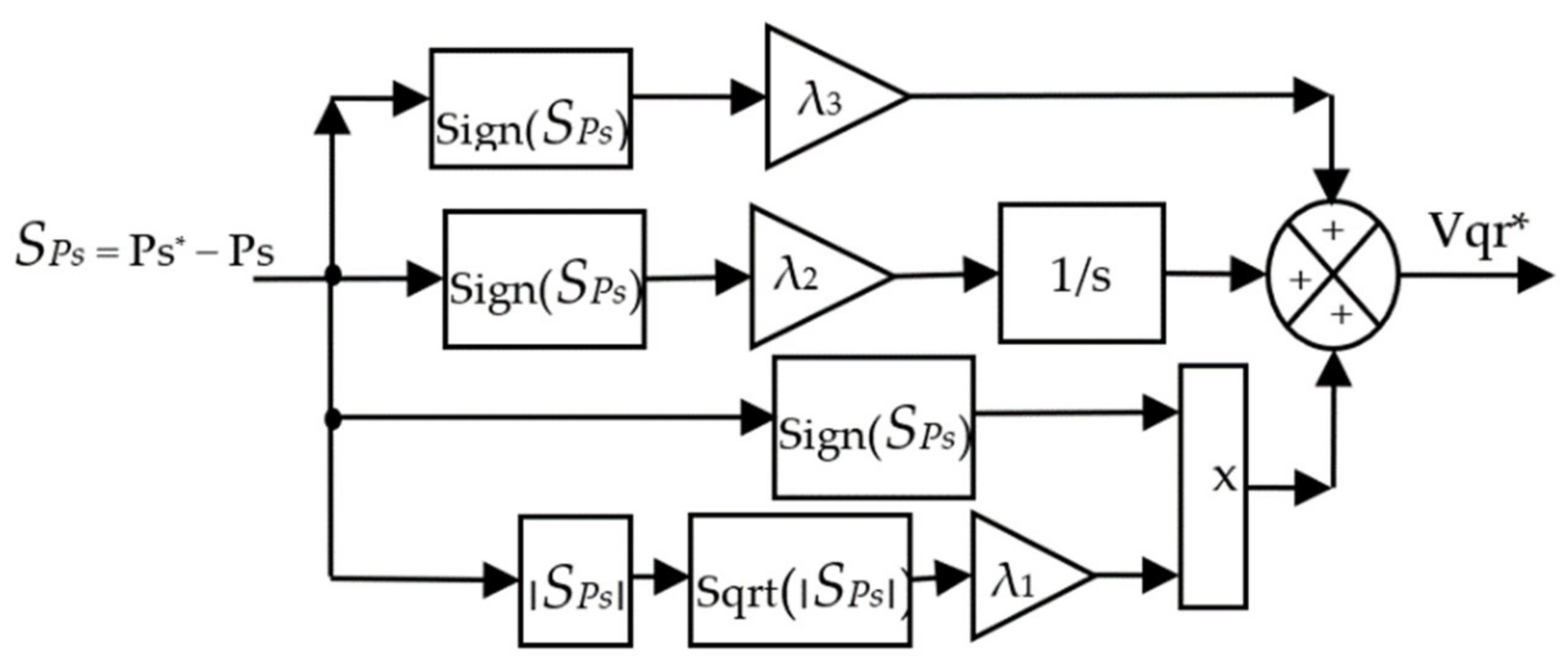
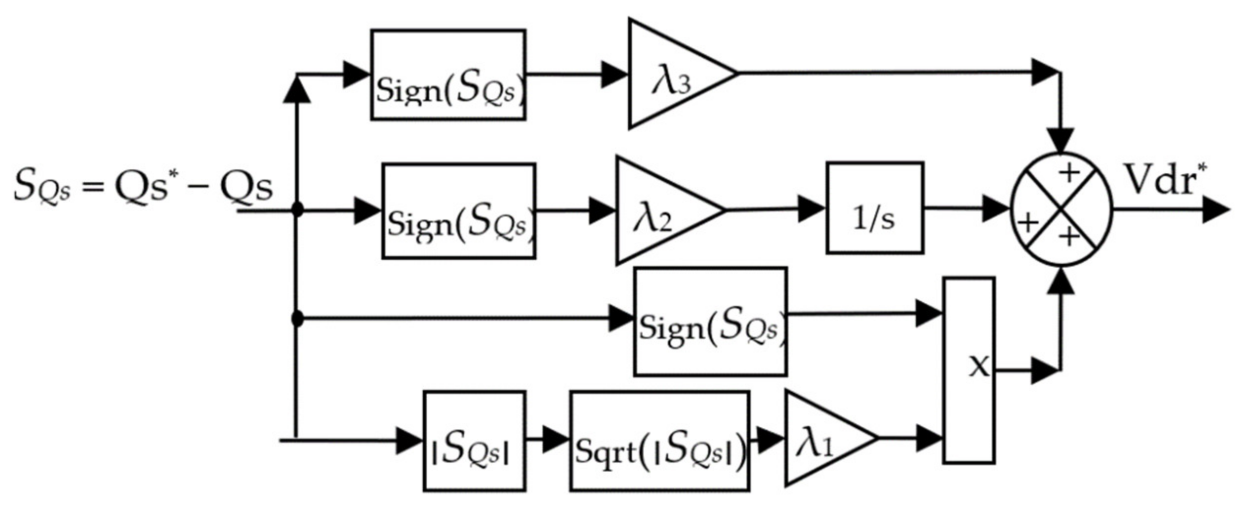
3. Third-Order Sliding Mode Control
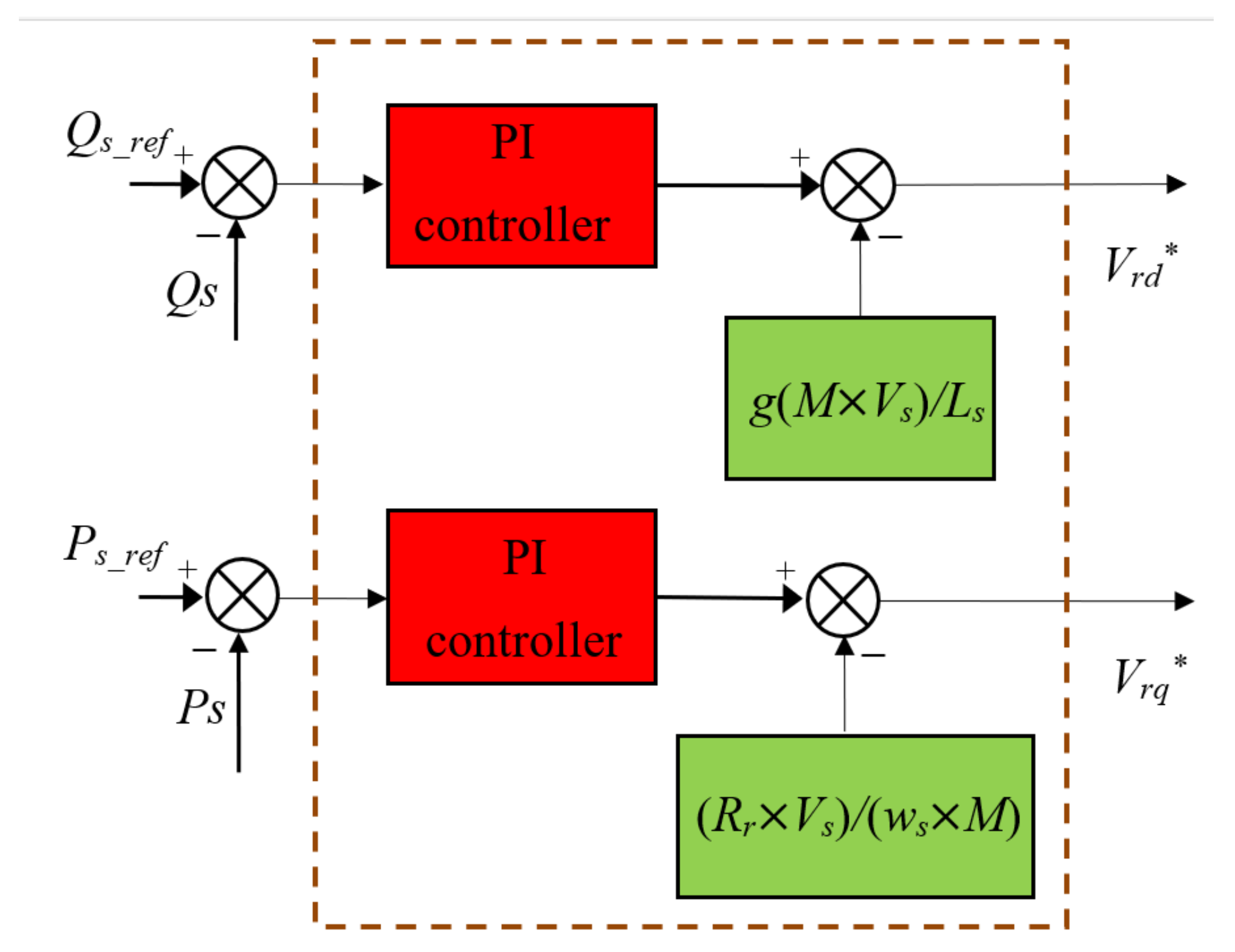
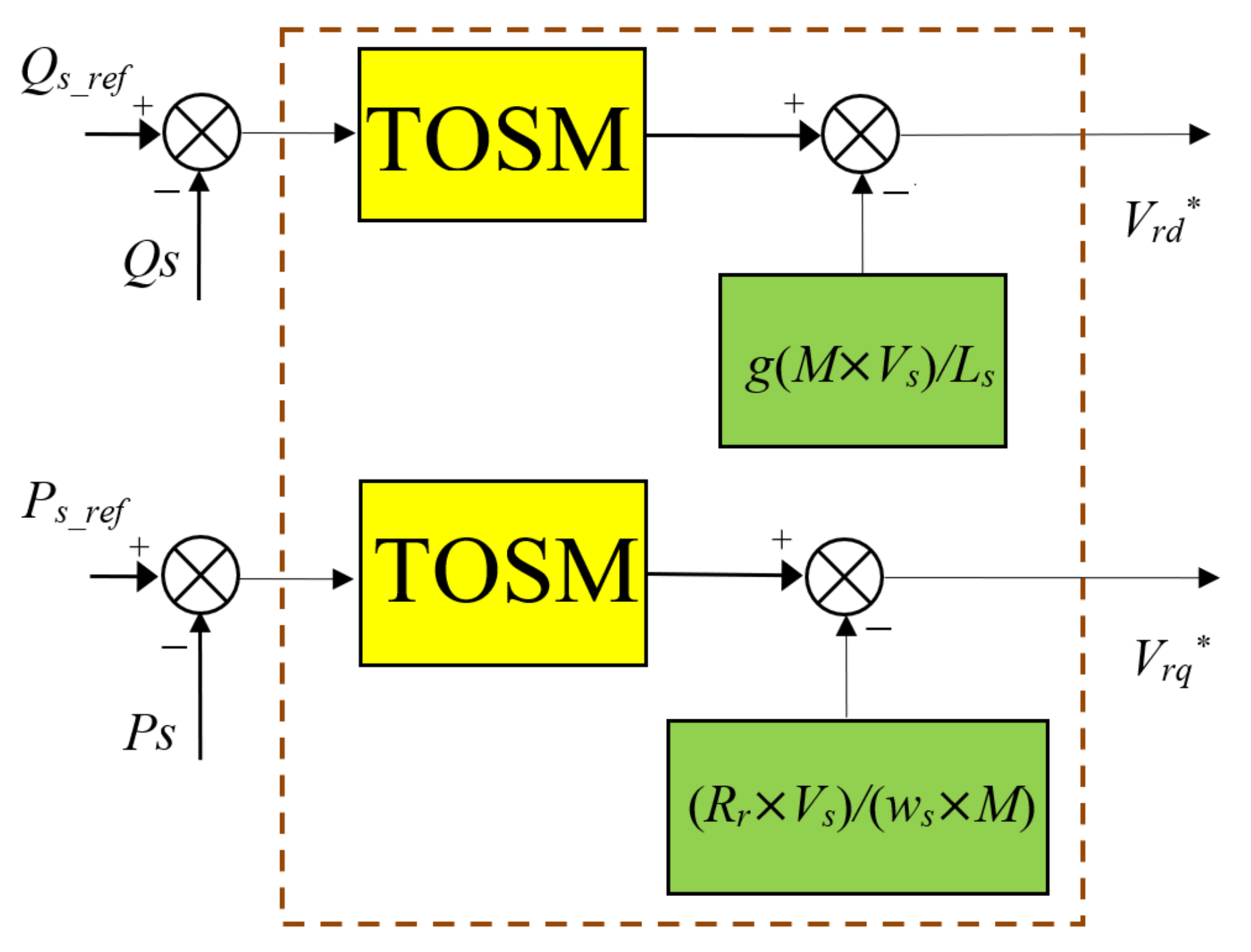
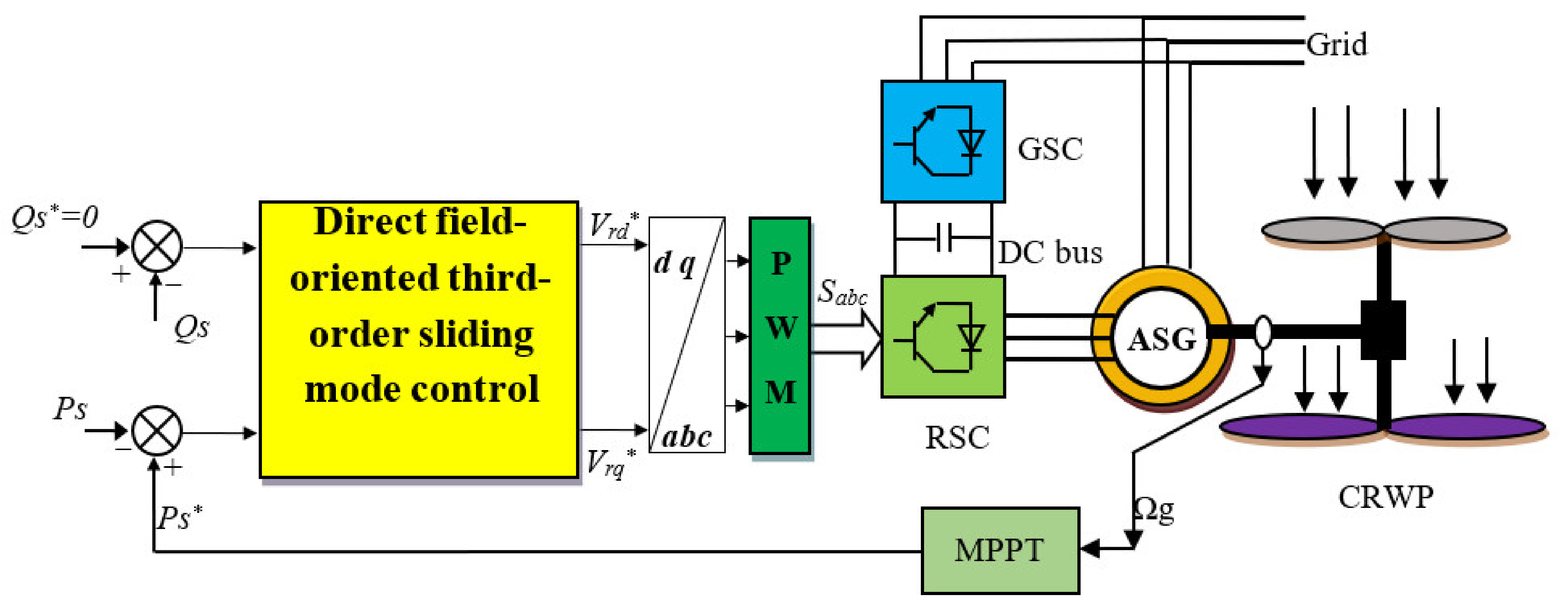
4. DFOC-TOSM Control
5. Numerical Simulation
5.1. First Test
5.2. Second Test
6. Conclusions
- A novel nonlinear controller was presented and confirmed with numerical simulation.
- A new DFOC strategy based on the proposed TOSM algorithm was presented and confirmed with numerical simulation.
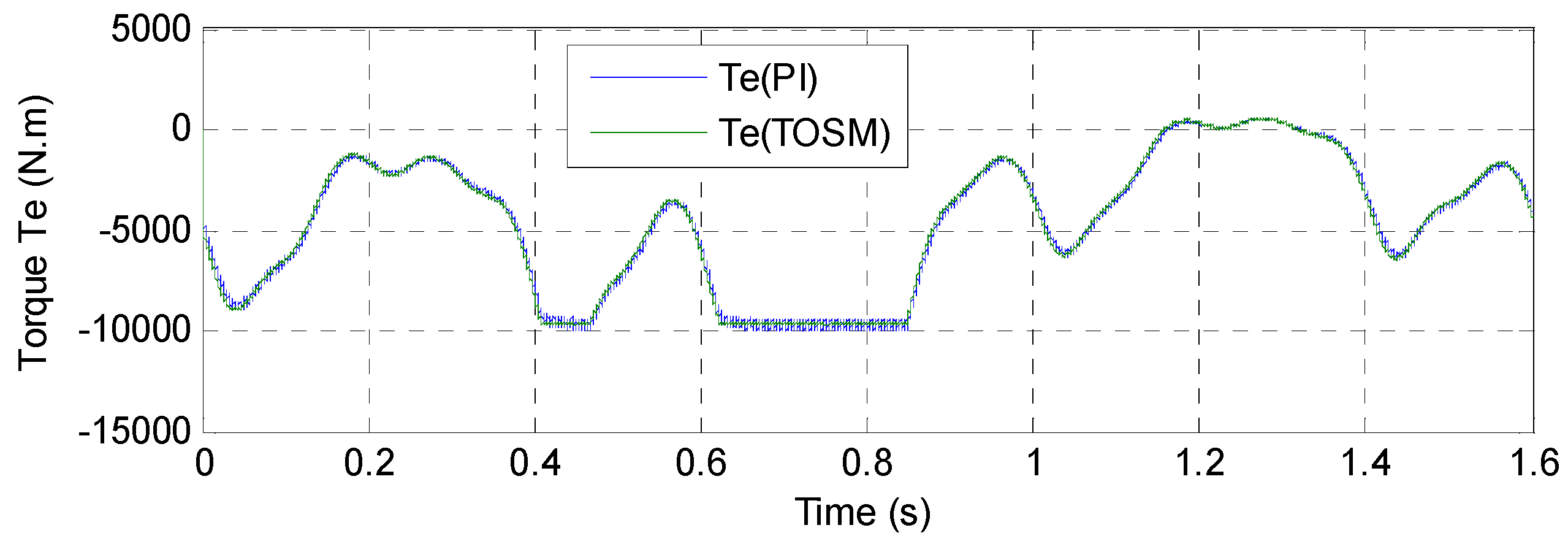
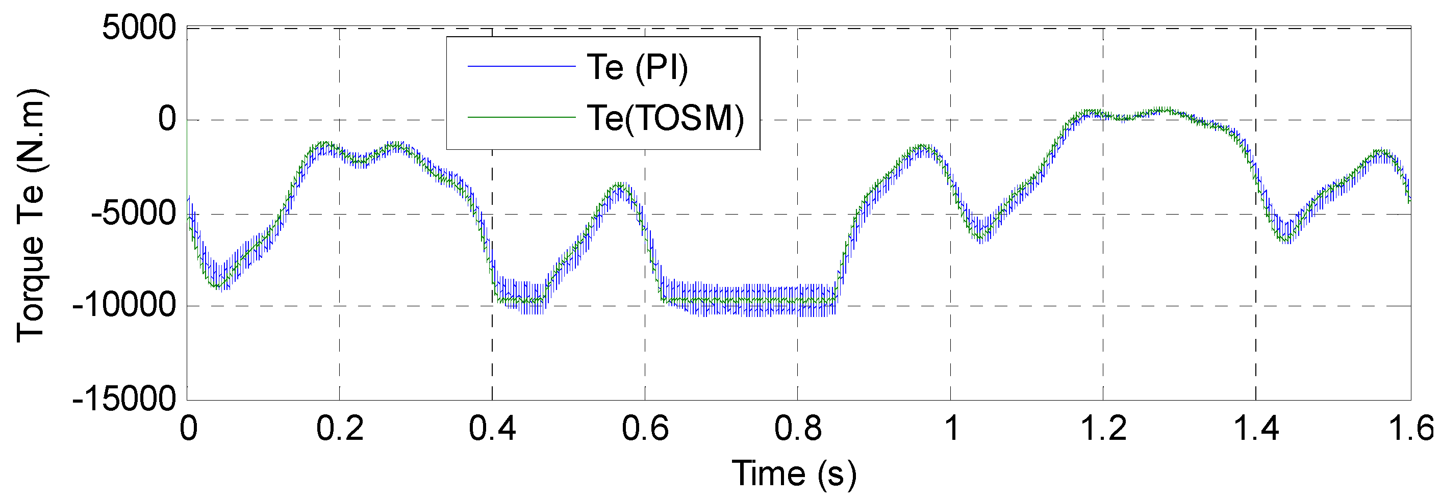
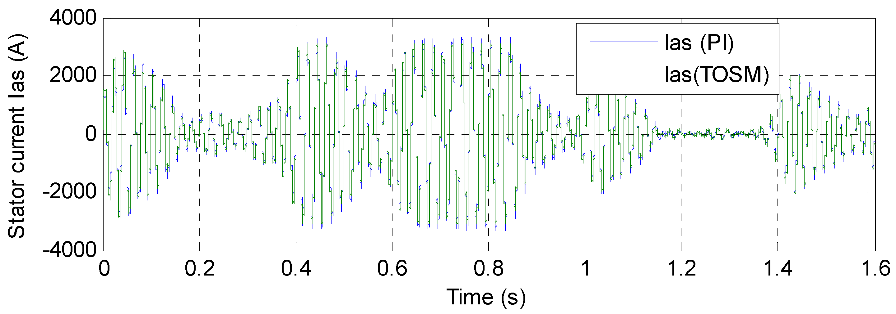
- A robust command technique was designed to minimize the ripples of current, active power, electromagnetic torque, and reactive power.
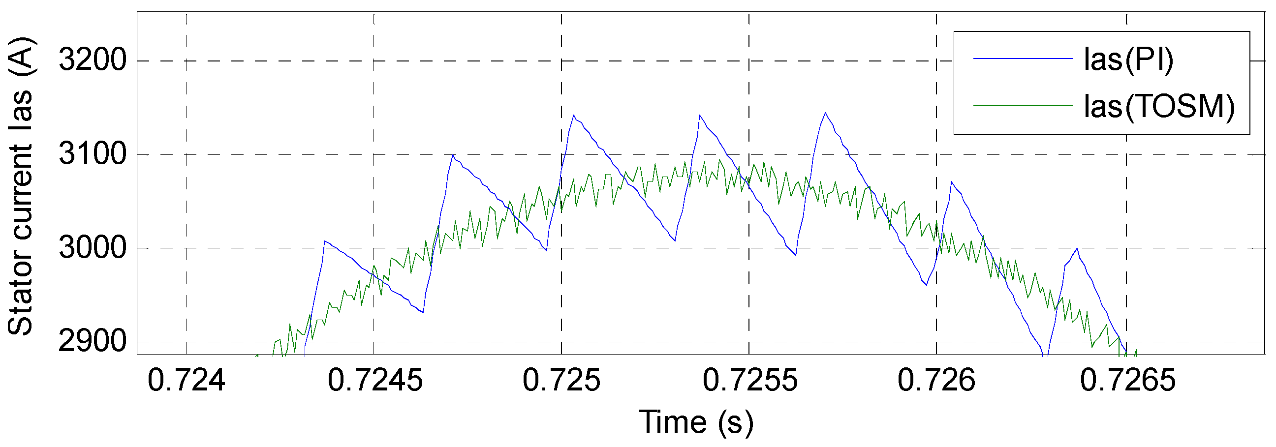
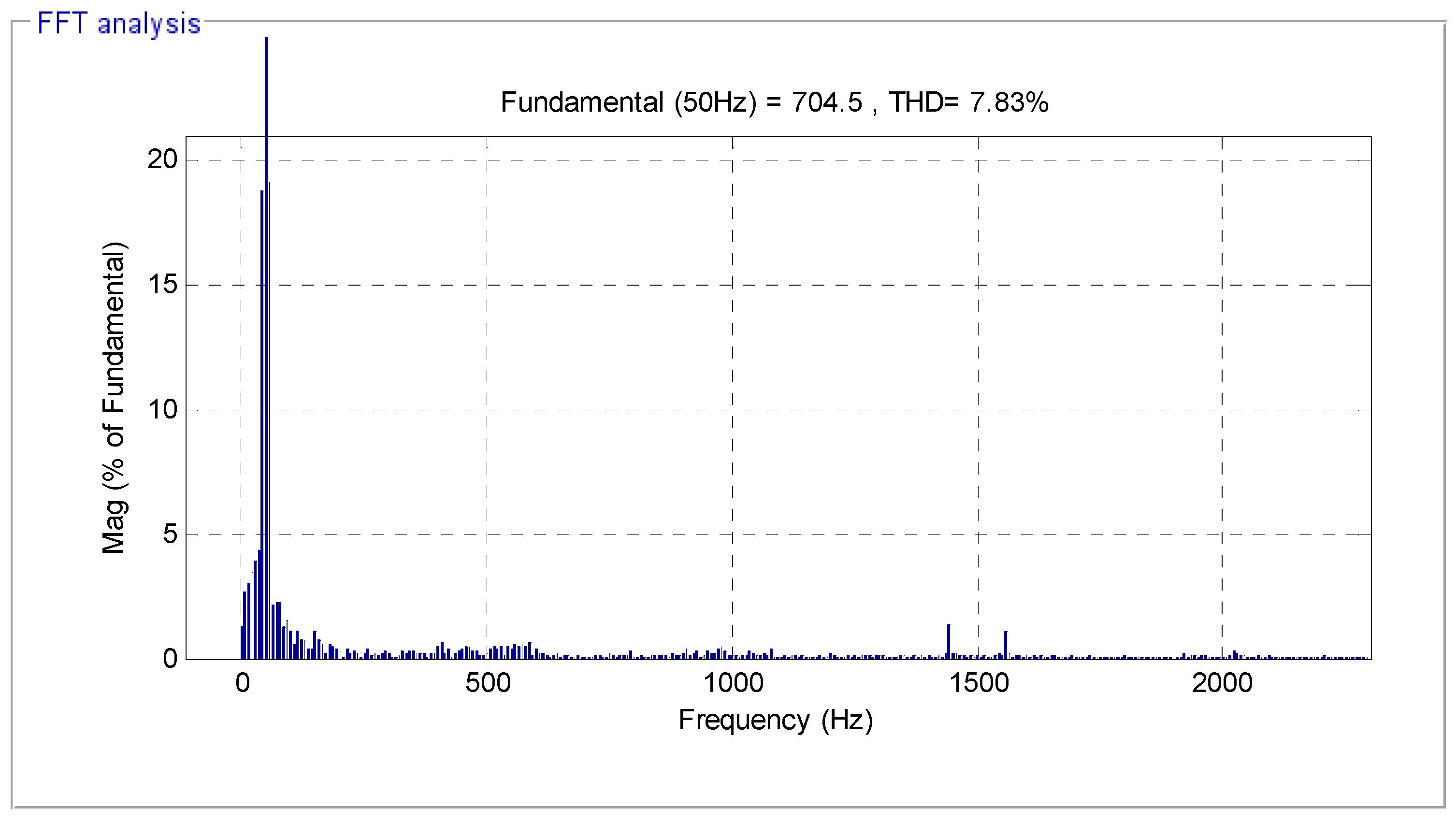
- The THD value of stator current was reduced by the proposed strategy.
Author Contributions
Funding
Institutional Review Board Statement
Informed Consent Statement
Data Availability Statement
Conflicts of Interest
References
- Xiong, L.; Li, P.; Li, H.; Wang, J. Sliding Mode Control of DFIG Wind Turbines with a Fast Exponential Reaching Law. Energies 2017, 10, 1788. [Google Scholar] [CrossRef] [Green Version]
- Levant, A. Robust exact differentiation via sliding mode technique. Automatica 1998, 34, 379–384. [Google Scholar] [CrossRef]
- Rezaei, M.M. A nonlinear maximum power point tracking technique for DFIG-based wind energy conversion systems. Eng. Sci. Technol. Int. J. 2018, 21, 901–908. [Google Scholar] [CrossRef]
- Hu, J.; Nian, H.; Hu, B.; He, Y.; Zhu, Z.Q. Direct active and reactive power regulation of DFIG using sliding-mode control approach. IEEE Trans. Energy Convers. 2010, 25, 1028–1039. [Google Scholar] [CrossRef]
- Benbouhenni, H. Sliding mode with neural network regulateur for DFIG using two-level NPWM strategy. Iran. J. Electr. Electron. Eng. 2019, 15, 411–419. [Google Scholar]
- Boudjema, Z.; Meroufel, A.; Djerriri, Y.; Bounadja, E. Fuzzy sliding mode control of a doubly fed induction generator for energy conversion. Carpathian J. Electron. Comput. Eng. 2013, 6, 7–14. [Google Scholar]
- Habib, B. ANFIS-sliding mode control of a DFIG supplied by a two-level SVPWM technique for wind energy conversion system. Int. J. Appl. Power Eng. 2020, 9, 36–47. [Google Scholar] [CrossRef]
- Abdolhadi, H.Z.; Markadeh, G.A.; Boroujeni, S.T. Sliding mode and terminal sliding mode control of cascaded doubly fed induction generator. Iran. J. Electr. Electron. Eng. 2021, 17, 1955. [Google Scholar]
- Xiao, L.; Zhang, L.; Gao, F.; Qian, J. Robust Fault-Tolerant Synergetic Control for Dual Three-Phase PMSM Drives Considering Speed Sensor Fault. IEEE Access 2020, 8, 78912–78922. [Google Scholar] [CrossRef]
- Hamid, C.; Aziz, D.; Seif Eddine, C.; Othmane, Z.; Mohammed, T.; Hasnae, E. Integral sliding mode control for DFIG based WECS with MPPT based on artificial neural network under a real wind profile. Energy Rep. 2021, 7, 4809–4824. [Google Scholar] [CrossRef]
- Du, H.; Chen, X.; Wen, G.; Yu, X.; Lü, J. Discrete-Time Fast Terminal Sliding Mode Control for Permanent Magnet Linear Motor. IEEE Trans. Ind. Electron. 2018, 65, 9916–9927. [Google Scholar] [CrossRef]
- Mobayen, S.; Bayat, F.; Lai, C.-C.; Taheri, A.; Fekih, A. Adaptive Global Sliding Mode Controller Design for Perturbed DC-DC Buck Converters. Energies 2021, 14, 1249. [Google Scholar] [CrossRef]
- Shehata, E.G. Sliding mode direct power control of RSC for DFIGs driven by variable speed wind turbines. Alex. Eng. J. 2015, 54, 1067–1075. [Google Scholar] [CrossRef] [Green Version]
- Haibo, L.; Heping, W.; Junlei, S. Attitude control for QTR using exponential nonsingular terminal sliding mode control. J. Syst. Eng. Electron. 2019, 30, 191–200. [Google Scholar] [CrossRef]
- Wang, Z.; Li, S.; Li, Q. Discrete-Time Fast Terminal Sliding Mode Control Design for DC–DC Buck Converters with Mismatched Disturbances. IEEE Trans. Ind. Inform. 2020, 16, 1204–1213. [Google Scholar] [CrossRef]
- Lin, X.; Shi, X.; Li, S. Adaptive Tracking Control for Spacecraft Formation Flying System via Modified Fast Integral Terminal Sliding Mode Surface. IEEE Access 2020, 8, 198357–198367. [Google Scholar] [CrossRef]
- Yu, X.; Man, Z. Model reference adaptive control systems with terminal sliding modes. Int. J. Control. 1996, 64, 1165–1176. [Google Scholar] [CrossRef]
- Feng, Y.; Yu, X.; Han, F. On nonsingular terminal sliding-mode control of nonlinear systems. Automatica 2013, 49, 1715–1722. [Google Scholar] [CrossRef]
- Morshed, M.J.; Fekih, A. A terminal sliding mode approach for the rotor side converter of a DFIG-based wind energy system. In Proceedings of the 2018 IEEE Conference on Control Technology and Applications (CCTA), Copenhagen, Denmark, 21–25 April 2018; pp. 1736–1740. [Google Scholar] [CrossRef]
- Sami, I.; Ullah, S.; Ali, Z.; Ullah, N.; Ro, J.-S. A Super Twisting Fractional Order Terminal Sliding Mode Control for DFIG-Based Wind Energy Conversion System. Energies 2020, 13, 2158. [Google Scholar] [CrossRef]
- Morshed, M.J.; Fekih, A. Second order integral terminal sliding mode control for voltage sag mitigation in DFIG-based wind turbines. In Proceedings of the 2017 IEEE Conference on Control Technology and Applications (CCTA), Mauna Lani, HI, USA, 27–30 August 2017; pp. 614–619. [Google Scholar] [CrossRef]
- Levant, A. Sliding order and sliding accuracy in sliding mode control. Int. J. Control. 1993, 58, 1247–1263. [Google Scholar] [CrossRef]
- Levant, A. Higher-order sliding modes, differentiation and output-feedback control. Int. J. Control. 2003, 76, 924–941. [Google Scholar] [CrossRef]
- Shah, A.P.; Mehta, A.J. Direct power control of DFIG using super-twisting algorithm based on second-order sliding mode control. In Proceedings of the 2016 14th International Workshop on Variable Structure Systems (VSS), Nanjing, China, 1–4 June 2016; pp. 136–141. Available online: https://ieeexplore.ieee.org/document/7506905 (accessed on 1 September 2021). [CrossRef]
- Alhato, M.M.; Ibrahim, M.N.; Rezk, H.; Bouallègue, S. An Enhanced DC-Link Voltage Response for Wind-Driven Doubly Fed Induction Generator Using Adaptive Fuzzy Extended State Observer and Sliding Mode Control. Mathematics 2021, 9, 963. [Google Scholar] [CrossRef]
- Habib, B.; Boudjema, Z.; Belaidi, A. Direct power control with NSTSM algorithm for DFIG using SVPWM technique. Iran. J. Electr. Electron. Eng. 2021, 17, 1–11. [Google Scholar]
- Habib, B.; Boudjema, Z.; Belaidi, A. DPC based on ANFIS super-twisting sliding mode algorithm of a doubly-fed induction generator for wind energy system. J. Eur. Des. Systèmes Autom. 2020, 53, 69–80. [Google Scholar]
- Farid, B.; Tarek, B.; Sebti, B. Fuzzy super twisting algorithm dual direct torque control of doubly fed induction machine. Int. J. Electr. Comput. Eng. 2021, 11, 3782–3790. [Google Scholar] [CrossRef]
- Mazen Alhato, M.; Bouallègue, S.; Rezk, H. Modeling and Performance Improvement of Direct Power Control of Doubly-Fed Induction Generator Based Wind Turbine through Second-Order Sliding Mode Control Approach. Mathematics 2020, 8, 2012. [Google Scholar] [CrossRef]
- Nasiri, M.; Mobayen, S.; Zhu, Q.M. Super-twisting sliding mode control for gear less PMSG-based wind turbine. Complexity 2019, 2019, 1–15. [Google Scholar] [CrossRef]
- Venu, G.; Kalyani, S.T. Design of fractional order based super twisting algorithm for BLDC motor. In Proceedings of the 2019 3rd International Conference on Trends in Electronics and Informatics (ICOEI), Tirunelveli, India, 23–25 April 2019; pp. 271–277. [Google Scholar] [CrossRef]
- Rakhtala, S.M.; Casavola, A. Real time voltage control based on a cascaded super twisting algorithm structure for DC-DC converters. IEEE Trans. Ind. Electron. 2021, 1. [Google Scholar] [CrossRef]
- Sriprang, S.; Nahid-Mobarakeh, B.; Takorabet, N.; Pierfederici, S.; Bizon, N.; Kuman, P.; Thounthong, P. Permanent Magnet Synchronous Motor Dynamic Modeling with State Observer-based Parameter Estimation for AC Servomotor Drive Application. Appl. Sci. Eng. Prog. 2019, 12, 286–297. [Google Scholar] [CrossRef]
- Benbouhenni, H. Intelligent super twisting high order sliding mode controller of dual-rotor wind power systems with direct attack based on doubly-fed induction generators. J. Electr. Eng. Electron. Control. Comput. Sci. 2021, 7, 1–8. Available online: https://jeeeccs.net/index.php/journal/article/view/219. (accessed on 1 September 2021).
- Shah, A.P.; Mehta, A.J. Direct power control of grid-connected DFIG using variable gain super-twisting sliding mode controller for wind energy optimization. In Proceedings of the IECON 2017—43rd Annual Conference of the IEEE Industrial Electronics Society, Beijing, China, 5–8 November 2017; pp. 2448–2454. [Google Scholar] [CrossRef]
- Kelkoul, B.; Boumediene, A. Stability analysis and study between classical sliding mode control (SMC) and super twisting algorithm (STA) for doubly fed induction generator (DFIG) under wind turbine. Energy 2021, 214, 118871. [Google Scholar] [CrossRef]
- Bouyekni, A.; Taleb, R.; Boudjema, Z.; Kahal, H. A second-order continuous sliding mode based on DFIG for wind-turbine-driven DFIG. Elektrotehniški Vestn. 2018, 85, 29–36. [Google Scholar]
- Boudjema, Z.; Taleb, R.; Djerriri, Y.; Yahdou, A. A novel direct torque control using second order continuous sliding mode of a doubly fed induction generator for a wind energy conversion system. Turk. J. Electr. Eng. Comput. Sci. 2017, 25, 965–975. [Google Scholar] [CrossRef] [Green Version]
- Benbouhenni, H.; Bizon, N. A Synergetic Sliding Mode Controller Applied to Direct Field-Oriented Control of Induction Generator-Based Variable Speed Dual-Rotor Wind Turbines. Energies 2021, 14, 4437. [Google Scholar] [CrossRef]
- Benbouhenni, H.; Bizon, N. Terminal Synergetic Control for Direct Active and Reactive Powers in Asynchronous Generator-Based Dual-Rotor Wind Power Systems. Electronics 2021, 10, 1880. [Google Scholar] [CrossRef]
- Astolfi, D. Wind Turbine Operation Curves Modelling Techniques. Electronics 2021, 10, 269. [Google Scholar] [CrossRef]
- Beik, O.; Al-Adsani, A.S. Active and Passive Control of a Dual Rotor Wind Turbine Generator for DC Grids. IEEE Access 2021, 9, 1987–1995. [Google Scholar] [CrossRef]
- Luo, X.; Niu, S. A Novel Contra-Rotating Power Split Transmission System for Wind Power Generation and Its Dual MPPT Control Strategy. IEEE Trans. Power Electron. 2017, 32, 6924–6935. [Google Scholar] [CrossRef]
- Zhao, Y.; Teng, D.; Li, D.; Zhao, X. Comparative Research on Four-Phase Dual Armature-Winding Wound-Field Doubly Salient Generator with Distributed Field Magnetomotive Forces for High-Reliability Application. IEEE Access 2021, 9, 12579–12591. [Google Scholar] [CrossRef]
- Zhao, W.; Lipo, T.A.; Kwon, B. A Novel Dual-Rotor, Axial Field, Fault-Tolerant Flux-Switching Permanent Magnet Machine with High-Torque Performance. IEEE Trans. Magn. 2015, 51, 1–4. [Google Scholar] [CrossRef]
- Fukami, T.; Momiyama, M.; Shima, K.; Hanaoka, R.; Takata, S. Steady-State Analysis of a Dual-Winding Reluctance Generator with a Multiple-Barrier Rotor. IEEE Trans. Energy Convers. 2008, 23, 492–498. [Google Scholar] [CrossRef]
- Wang, Y.; Niu, S.; Fu, W. A Novel Dual-Rotor Bidirectional Flux-Modulation PM Generator for Stand-Alone DC Power Supply. IEEE Trans. Ind. Electron. 2019, 66, 818–828. [Google Scholar] [CrossRef]
- Yahdou, A.; Djilali, A.B.; Boudjema, Z.; Mehedi, F. Improved vector control of a counter-rotating wind turbine system using adaptive backstepping sliding mode. J. Eur. Des. Syst. Autom. 2020, 53, 645–651. [Google Scholar]
- Anthony, M.; Prasad, V.; Kannadasan, R.; Mekhilef, S.; Alsharif, M.H.; Kim, M.-K.; Jahid, A.; Aly, A.A. Autonomous Fuzzy Controller Design for the Utilization of Hybrid PV-Wind Energy Resources in Demand Side Management Environment. Electronics 2021, 10, 1618. [Google Scholar] [CrossRef]
- Huangfu, Y.; Xu, J.; Zhao, D.; Liu, Y.; Gao, F. A Novel Battery State of Charge Estimation Method Based on a Super-Twisting Sliding Mode Observer. Energies 2018, 11, 1211. [Google Scholar] [CrossRef] [Green Version]
- Ha, L.N.N.T.; Hong, S.K. Robust Dynamic Sliding Mode Control-Based PID–Super Twisting Algorithm and Disturbance Observer for Second-Order Nonlinear Systems: Application to UAVs. Electronics 2019, 8, 760. [Google Scholar] [CrossRef] [Green Version]
- Shi, D.; Wu, Z.; Chou, W. Super-Twisting Extended State Observer and Sliding Mode Controller for Quad rotor UAV Attitude System in Presence of Wind Gust and Actuator Faults. Electronics 2018, 7, 128. [Google Scholar] [CrossRef] [Green Version]
- Listwan, J. Application of super-twisting sliding mode controllers in direct field-oriented control system of six-phase induction motor: Experimental studies. Power Electron. Drives 2018, 3, 23–34. [Google Scholar] [CrossRef] [Green Version]
- Shen, X.; Liu, J.; Marquez, A.; Luo, W.; Leon, J.I.; Vazquez, S.; Franquelo, L.G. A High-Gain Observer-Based Adaptive Super-Twisting Algorithm for DC-Link Voltage Control of NPC Converters. Energies 2020, 13, 1110. [Google Scholar] [CrossRef] [Green Version]
- Chen, S.; Zhang, X.; Wu, X.; Tan, G.; Chen, X. Sensorless Control for IPMSM Based on Adaptive Super-Twisting Sliding-Mode Observer and Improved Phase-Locked Loop. Energies 2019, 12, 1225. [Google Scholar] [CrossRef] [Green Version]
- Uddin, W.; Zeb, K.; Adil Khan, M.; Ishfaq, M.; Khan, I.; Islam, S.U.; Kim, H.-J.; Park, G.S.; Lee, C. Control of Output and Circulating Current of Modular Multilevel Converter Using a Sliding Mode Approach. Energies 2019, 12, 4084. [Google Scholar] [CrossRef] [Green Version]
- Dendouga, A. Conventional and Second Order Sliding Mode Control of Permanent Magnet Synchronous Motor Fed by Direct Matrix Converter: Comparative Study. Energies 2020, 13, 5093. [Google Scholar] [CrossRef]
- Zeb, K.; Busarello, T.D.C.; Ul Islam, S.; Uddin, W.; Raghavendra, K.V.G.; Khan, M.A.; Kim, H.-J. Design of Super Twisting Sliding Mode Controller for a Three-Phase Grid-connected Photovoltaic System under Normal and Abnormal Conditions. Energies 2020, 13, 3773. [Google Scholar] [CrossRef]
- Kafi, M.R.; Hamida, M.A.; Chaoui, H.; Belkacemi, R. Sliding Mode Self-Sensing Control of Synchronous Machine Using Super Twisting Interconnected Observers. Energies 2020, 13, 4199. [Google Scholar] [CrossRef]
- Liu, Y.; Fang, J.; Tan, K.; Huang, B.; He, W. Sliding Mode Observer with Adaptive Parameter Estimation for Sensorless Control of IPMSM. Energies 2020, 13, 5991. [Google Scholar] [CrossRef]
- Valenzuela, F.A.; Ramírez, R.; Martínez, F.; Morfín, O.A.; Castañeda, C.E. Super-Twisting Algorithm Applied to Velocity Control of DC Motor without Mechanical Sensors Dependence. Energies 2020, 13, 6041. [Google Scholar] [CrossRef]
- Azzouz, T.; Abdelhamid, B. Performance of PI controller for control of active and reactive power in DFIG operating in a grid-connected variable speed wind energy conversion system. Front. Energy 2014, 8, 371–378. [Google Scholar] [CrossRef]
- Karima, B.; Akkila, B. Output power control of a variable wind energy conversion system. Rev. Sci. Tech. Electrotech. Energ. 2017, 62, 197–202. [Google Scholar]
- Amrane, F.; Chaiba, A. A novel direct power control for grid-connected doubly fed induction generator based on hybrid artificial intelligent control with space vector modulation. Rev. Sci. Tech. Electrotech. Energ. 2016, 61, 263–268. [Google Scholar]
- Amrane, F.; Chaiba, A.; Badr Eddine, B.; Saad, M. Design and implementation of high performance field oriented control for grid-connected doubly fed induction generator via hysteresis rotor current controller. Rev. Roum. Rev. Sci. Tech. Electrotech. Energ. 2016, 61, 319–324. [Google Scholar]
- Yusoff, N.A.; Razali, A.M.; Karim, K.A.; Sutikno, T.; Jidin, A. A Concept of Virtual-Flux Direct Power Control of Three-Phase AC-DC Converter. Int. J. Power Electron. Drive Syst. 2017, 8, 1776–1784. [Google Scholar] [CrossRef]
- Quan, Y.; Hang, L.; He, Y.; Zhang, Y. Multi-Resonant-Based Sliding Mode Control of DFIG-Based Wind System under Unbalanced and Harmonic Network Conditions. Appl. Sci. 2019, 9, 1124. [Google Scholar] [CrossRef] [Green Version]
- Yahdou, A.; Hemici, B.; Boudjema, Z. Second order sliding mode control of a dual-rotor wind turbine system by employing a matrix converter. J. Electr. Eng. 2016, 16, 1–11. [Google Scholar]
- Yaichi, I.; Semmah, A.; Wira, P.; Djeriri, Y. Super-twisting sliding mode control of a doubly-fed induction generator based on the SVM strategy. Period. Polytech. Electr. Eng. Comput. Sci. 2019, 63, 178–190. [Google Scholar] [CrossRef]


| Control Techniques | Controller | Complexity | Current Oscillations | Reference Tracking | Dynamic Responses | Sensitivity to Parameter Change | THD (%) of Current |
|---|---|---|---|---|---|---|---|
| DTC control | Hysteresis controller | Low | High | Good | Good | High | High |
| DPC control | Hysteresis controller | Low | High | Good | Good | High | High |
| FOC control | PI | High | High | Acceptable | Acceptable | High | High |
| Proposed technique (DFOC-TOSMC) | TOSM controller | High | Low | Excellent | Excellent | Medium | Low |
| Criteria | Control Techniques | |
|---|---|---|
| DFOC | DFOC-TOSM | |
| Reactive and active power tracking | Well | Excellent |
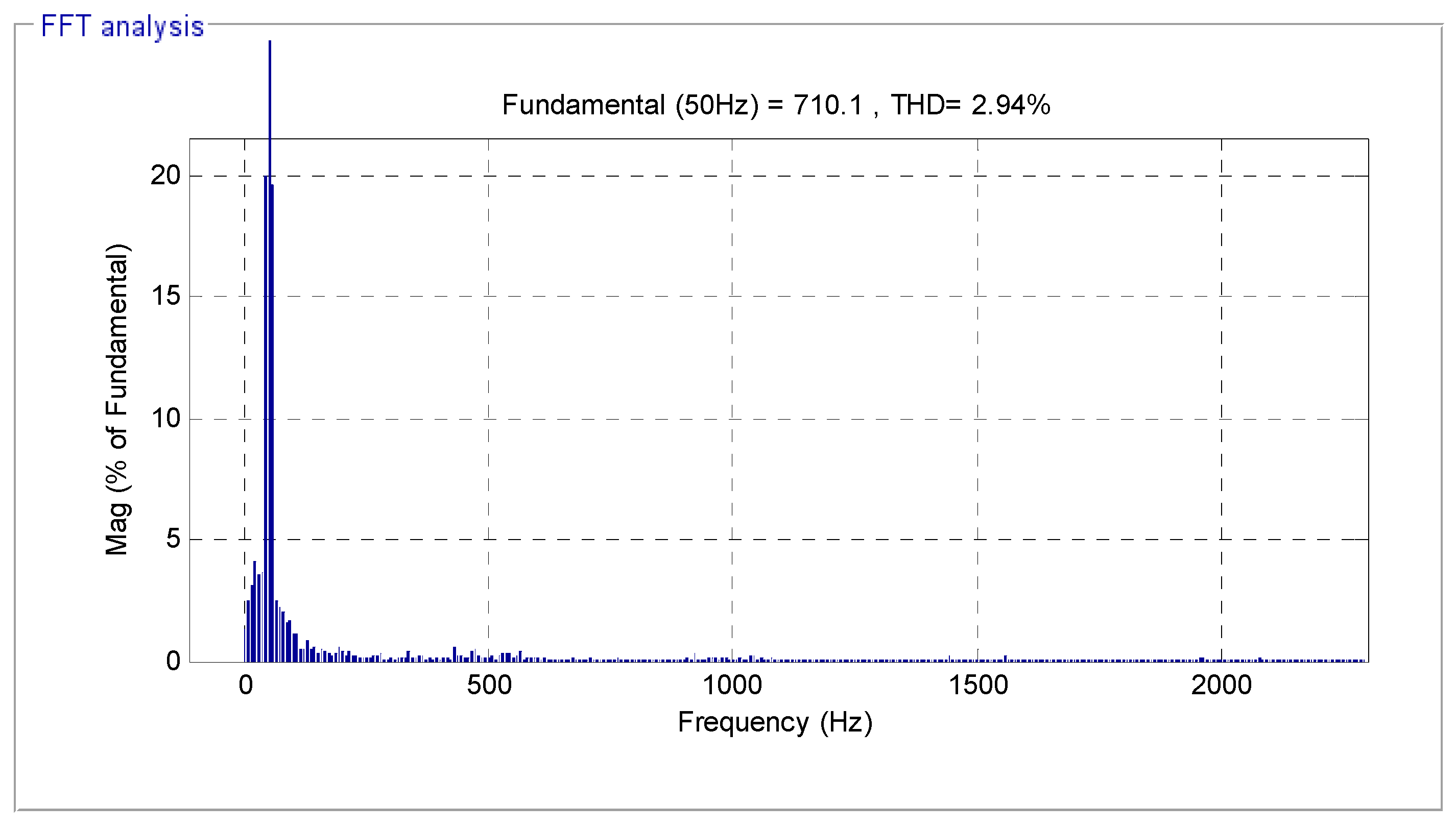
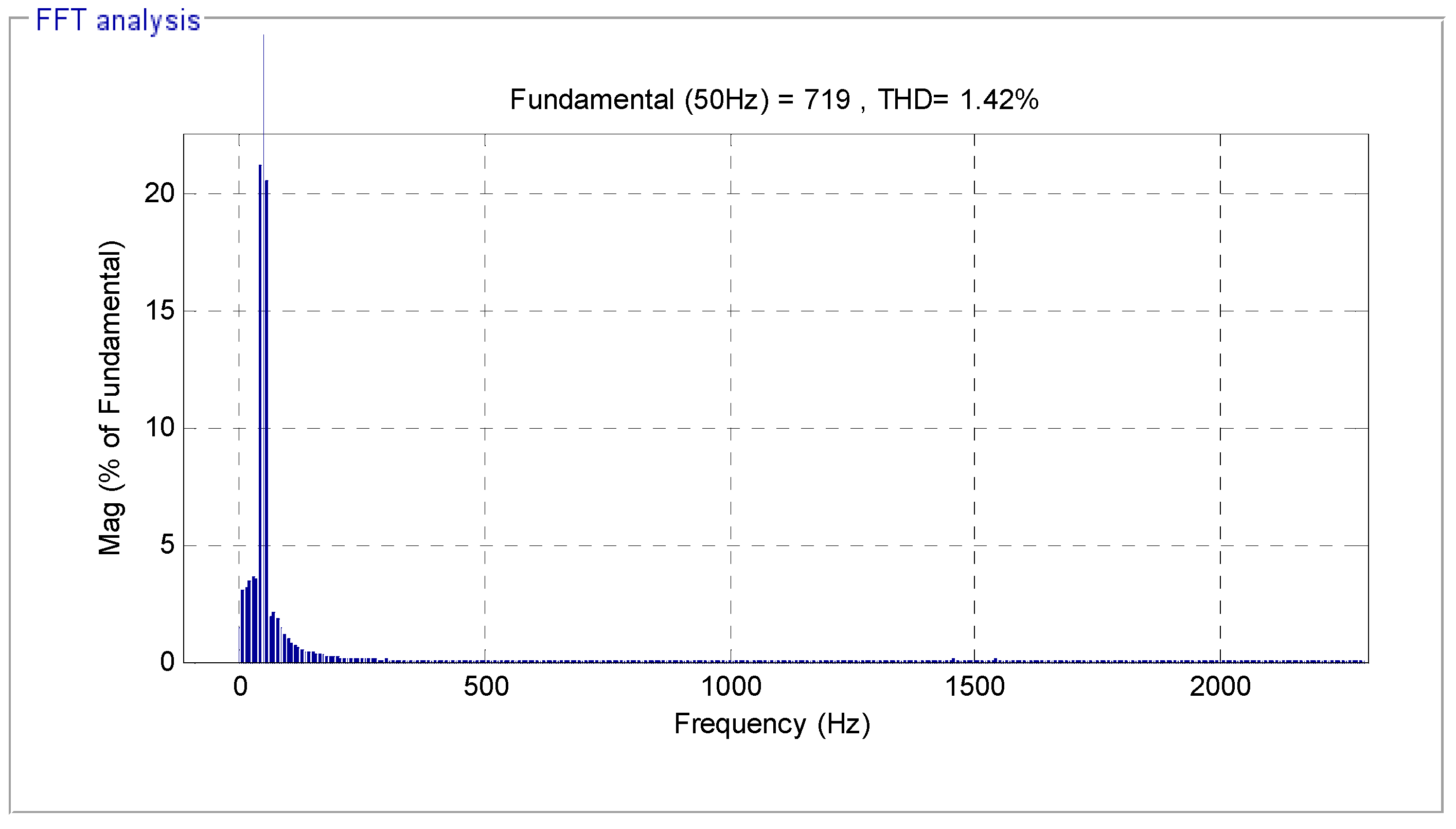
| THD (%) | 2.94 | 1.42 |
| Reactive and active power ripples | Acceptable | Excellent |
| Dynamic response (s) | Medium | Fast |
| Reactive power: ripples (VAR) | Around 20,000 | Around 1100 |
| Torque: ripple (N.m) | Around 500 | Around 80 |
| Settling time (ms) | High | Medium |
| Overshoot (%) | Remarkable ≈ 19% | Neglected ≈ 1.5% |
| Sensitivity to parameter change | High | Medium |
| Active power: ripples (W) | Around 10,000 | Around 1000 |
| Simplicity of converter and filter design | Simple | Simple |
| Rise Time (s) | High | Medium |
| Stator current ripple (VAR) | Around 100 | Around 22 |
| Simplicity of calculations | Simple | Rather complicated |
| Improvement of transient performance | Good | Excellent |
| Quality of stator current | Acceptable | Excellent |
| References | Techniques | THD (%) |
|---|---|---|
| Ref. [6] | Fuzzy SMC technique | 3.05 |
| Ref. [38] | Direct torque command | 2.95 |
| Ref. [64] | FOC with hysteresis current controller | 3.70 |
| Ref. [66] | Virtual flux DPC method | 4.19 |
| DPC | 4.88 | |
| Ref. [67] | Integral SMC technique | 9.71 |
| Multi-resonant-based sliding mode controller (MRSMC) | 3.14 | |
| Ref. [68] | SOSMC method | 3.13 |
| Ref. [69] | DPC control with STA controller | 1.66 |
| Designed strategies | DFOC-PI | 2.94 |
| DFOC-TOSM | 1.42 |
Publisher’s Note: MDPI stays neutral with regard to jurisdictional claims in published maps and institutional affiliations. |
© 2021 by the authors. Licensee MDPI, Basel, Switzerland. This article is an open access article distributed under the terms and conditions of the Creative Commons Attribution (CC BY) license (https://creativecommons.org/licenses/by/4.0/).
Share and Cite
Benbouhenni, H.; Bizon, N. Third-Order Sliding Mode Applied to the Direct Field-Oriented Control of the Asynchronous Generator for Variable-Speed Contra-Rotating Wind Turbine Generation Systems. Energies 2021, 14, 5877. https://doi.org/10.3390/en14185877
Benbouhenni H, Bizon N. Third-Order Sliding Mode Applied to the Direct Field-Oriented Control of the Asynchronous Generator for Variable-Speed Contra-Rotating Wind Turbine Generation Systems. Energies. 2021; 14(18):5877. https://doi.org/10.3390/en14185877
Chicago/Turabian StyleBenbouhenni, Habib, and Nicu Bizon. 2021. "Third-Order Sliding Mode Applied to the Direct Field-Oriented Control of the Asynchronous Generator for Variable-Speed Contra-Rotating Wind Turbine Generation Systems" Energies 14, no. 18: 5877. https://doi.org/10.3390/en14185877