Article

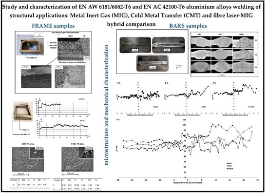
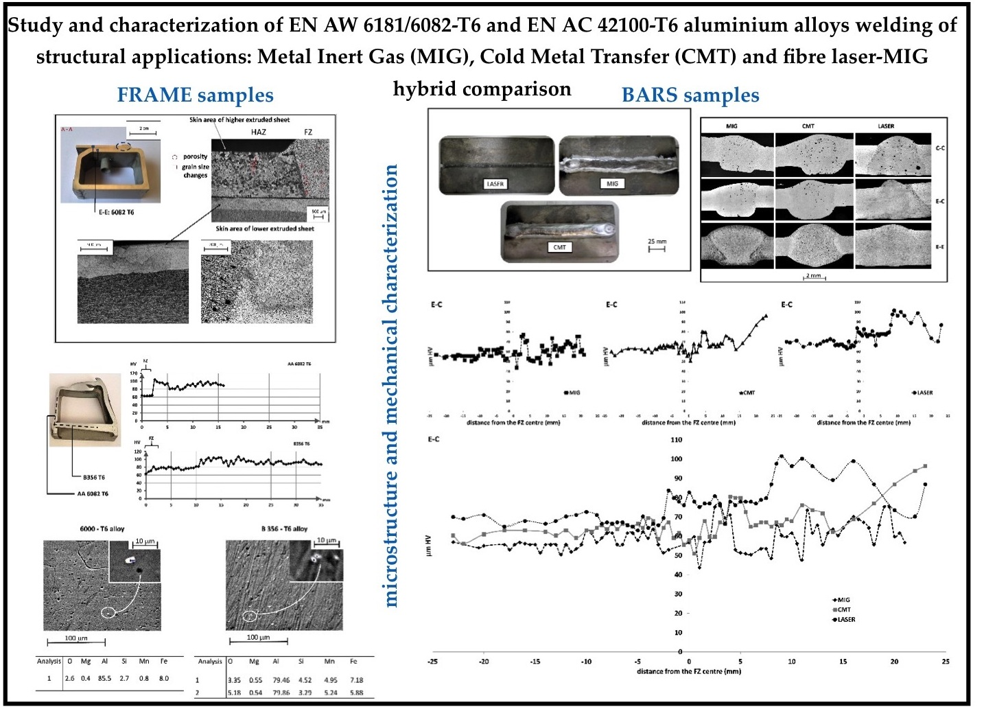
Study and Characterization of EN AW 6181/6082-T6 and EN AC 42100-T6 Aluminum Alloy Welding of Structural Applications: Metal Inert Gas (MIG), Cold Metal Transfer (CMT), and Fiber Laser-MIG Hybrid Comparison

by
Giovanna Cornacchia
* and
Silvia Cecchel
DIMI, Department of Industrial and Mechanical Engineering, University of Brescia, via Branze 38, 25123 Brescia, Italy
*
Author to whom correspondence should be addressed.
Metals 2020, 10(4), 441; https://doi.org/10.3390/met10040441
Submission received: 18 February 2020 / Revised: 24 March 2020 / Accepted: 26 March 2020 / Published: 27 March 2020
(This article belongs to the Special Issue Advanced Welding Technology in Metals)

Abstract

:
The present research investigates the effects of different welding techniques, namely traditional metal inert gas (MIG), cold metal transfer (CMT), and fiber laser-MIG hybrid, on the microstructural and mechanical properties of joints between extruded EN AW 6181/6082-T6 and cast EN AC 42100-T6 aluminum alloys. These types of weld are very interesting for junctions of Al-alloys parts in the transportation field to promote the lightweight of a large scale chassis. The weld joints were characterized through various metallurgical methods including optical microscopy and hardness measurements to assess their microstructure and to individuate the nature of the intermetallics, their morphology, and distribution. The results allowed for the evaluation of the discrepancies between the welding technologies (MIG, CMT, fiber laser) on different aluminum alloys that represent an exhaustive range of possible joints of a frame. For this reason, both simple bar samples and real junctions of a prototype frame of a sports car were studied and, compared where possible. The study demonstrated the higher quality of innovative CMT and fiber laser-MIG hybrid welding than traditional MIG and the comparison between casting and extrusion techniques provide some inputs for future developments in the automotive field.

Graphical Abstract

1. Introduction

1.1. Background

Aluminum alloys have recently increased their employment in different engineering fields, especially for transport, due to their excellent properties including good corrosion resistance, high strength, good formability, and low density [1,2,3,4]. The current main requirements of the automotive field such as the necessity of reducing emissions, the improvement of vehicle performance, and the preservation of safety targets [5,6,7] imply a further need to improve and study lightweight structures fabricated from aluminum alloys [8,9,10]. The manufacturing of complex shapes, where welded joints are usually required, is even more challenging.

1.2. Aluminum Alloys Weldability

The welding of aluminum alloys is considered a slightly difficult process due to its high thermal and electrical conductivity, high thermal expansion coefficient, refractory aluminum oxide (Al2O3) formation tendency, and low stiffness. These characteristics, in general, make these alloys sensitive to defect formation that may lead to the loss of chemical, metallurgical, and mechanical properties. Typical welding defects in aluminum alloys are gas porosity, oxide inclusions and/or oxide filming, solidification (hot) cracking or hot tearing, reduced strength in the weld and heat affected zone (HAZ), lack of fusion, and reduced corrosion and electrical resistance. These defects determine reduced strength and corrosion in the fusion zone (FZ) and HAZ, with a general decrease in mechanical properties. These defects are generally reduced, providing efficient protection from the contamination of atmospheric gases to the weld pool or/and decreasing the influence of the weld thermal load by using welding processes with higher energy density [11,12].
These problems have to be faced, mainly due to the increasing employment of Al in complex vehicle parts, which implies a higher number of potential applications of Al hybrid structures. For example, during the last few years, both cast and wrought Al parts have been introduced in automotive complex shapes, which entails the need to join them into the final structure. Indeed, the dissimilar aluminum alloy joint can combine good strength and corrosion resistance, which is typical of this material, with exceptional castability used where complex sub-sections are needed, and excellent mechanical properties, achieved in other specific areas made of extruded parts.

1.3. Aluminum Alloys for Automotive Field

Against this background, the Al–Si–Mg alloy class is one of the most widely used for the production of aluminum casting components. In particular, the cast Al−7Si−Mg (EN AC 42100, also defined as A 356) alloy is widely used in automotive applications thanks to its high specific strength. Its microstructure consists of primary α (Al) grains and eutectic (Al–Si) structures. T6 heat treatment is normally used to obtain the desired mechanical properties. The solution treatment dissolves the β phase (Mg2Si particles) in the Al matrix, homogenizes the alloying elements in the casting, and modifies the morphology of the eutectic structures [13,14,15,16]. Wrought aluminum is a widely used alloy in the automotive field, especially the heat-treatable 6xxx series, which is characterized by high strength and good corrosion resistance [17]. Two of the most commonly used are the wrought EN AW-6181-T6 and EN AW-6082-T6 aluminum alloys. These are age-hardenable alloys, thus their mechanical properties are mainly controlled by the hardening precipitates contained in the material. When the material is subjected to a solution heat treatment followed by a quenching and a tempering treatment, their mechanical properties reach their highest level. According to the literature [18,19,20], the T6 temper of the 6xxx alloys involves very thin precipitates, namely β’’needle shaped precipitates, with a nanometric size and is partially coherent with the matrix. One of the most interesting characteristics of these alloys is the good weldability that, along with other properties, makes them very attractive in transport for complex structures assembled by welding [21,22]. Several works have studied the welding of aluminum and other alloys such as magnesium, steel, or titanium [23,24,25,26]. Only a limited number of scientific papers [27,28,29,30,31,32] have investigated the welding of dissimilar aluminum alloys together. These papers mainly deal with friction stir welding (FSW) [33,34], which, despite its potential, still has a high cost that needs to be improved in order to be used in industrial high volume applications. Wang et al. [35] studied the tensile properties and microstructure of a joined wrought EN AW-6181 aluminum alloy and vacuum high pressure die cast A356 aluminum alloy by using the metal inert gas (MIG) technique. The results showed that the low strengths of the A356-T6 alloy should be attributed to the absence of Mg-based intermetallic phase, coarse grain, and porosity, but the effect of the microstructure of the two base metals (BM) on the mechanical properties was not reported. An interesting study by Nie et al. [36] examined the microstructure, distribution of alloying elements, and mechanical properties of the wrought aluminum alloy 6061-T6 and cast aluminum alloy A356-T6 joined using a pulse MIG welding process. Additionally, the influence of welding speed on the microstructure and mechanical properties of the joints was investigated. They observed brittle Fe-rich phases in the partially melted zone and minimum hardness in the A356 aluminum alloy side. Some authors have recently tried to apply hybrid laser-arc welding to Fe–Al dissimilar joints [37], but in that case, the process was instable because of the significant difference in the thermal- and fluid-dynamic properties of the two metals. On the other hand, for this configuration, full penetration and low defectiveness were obtained by laser offset welding. Wang et al. applied laser welding with different beam oscillating modes on 5A06 aluminum alloy sheets and found that welding defects such as welding porosity could be improved by laser beam oscillation [38].

1.4. Welding Techniques Examined

In recent times, alternative welding techniques have been successfully applied to aluminum alloys.
MIG welding is an electric arc welding process that uses a continuously fed wire into the weld pool. It can be used to join long stretches of metal without stopping. Among the main advantages of this type of weld are that good quality welds can be produced much faster and there is flexibility for a wide variety of alloys. In addition, thanks to the gas protection, there is very little loss of alloying elements. Unfortunately, MIG welding cannot be used in vertical or overhead welding positions because of the high heat input, the fluidity of the weld puddle, and the complexity of the equipment [11,39].
CMT is a form of modified MIG welding based on the short-circuiting transfer process that guarantees interesting achievements such as process stability, reproducibility, and cost-effectiveness. This process differs from MIG welding only in the type of mechanical droplet cutting method that provides controlled material deposition and low thermal input by incorporating an innovative wire feed system coupled with a high-speed digital control. The two main advantages of the CMT process are the low heat input and the occurrence of short circuits in a stable controlled manner [40,41,42,43].
Laser welding is a very interesting joint process due to the high welding speed, smaller heat-affected zone (HAZ), and low deformation. Unfortunately, the high cooling rates can lead to the formation of hardening structures that increases hardness, decreases plasticity of the weld joint and HAZ, and increases the level of residual stresses. Fiber laser welding is one of many laser processes where the laser light is generated in a remote source and guided to the work piece by a flexible delivery optic fiber. The main benefits of this type of weld are the good beam quality, high precision control, lower heat input, lower electrical energy consumption, low cost of maintenance, and compact size. Welding with the laser technique requires alignment, fixation, and welding process control. This critical procedure can be solved by using the twin spot laser technique with filler wire or hybrid arc-laser welding, but will decrease the welding speed. One of the ways to solve this problem is the use of laser beam wobbling mode [11,12,44,45,46,47,48,49,50].

1.5. Aim of Work

The aim of the present study was to extend this last study and to investigate the feasibility, microstructural, and mechanical properties of EN AW-6181 or 6082-T6/EN and AC 42100-T6 aluminum alloy joints by considering other welding techniques. In particular, the present article analyzes and compares the metal inert gas technique (MIG), with cold metal transfer (CMT) and fiber laser-MIG hybrid welding through the evaluation of the final microstructure, the analyses of grain size, second-phase fraction, and dissolution of the precipitate in HAZ and FZ. Optical microscopy (OM) as well as the mechanical properties of welds (micro and macro hardness) were used. Junctions of both samples and a prototype frame of a sports car were examined and compared.

2. Materials and Methods

2.1. Base Metal and Filler Wire Materials

In order to be as reliable as possible, the analyses were carried out on samples machined from a prototype of an actual sports car frame composed of different aluminum alloys welded together. It is worthwhile noting that the opportunity to study actual automotive parts is extremely relevant to evaluate the real quality of the welds, especially considering that the automotive sector is highly demanding in terms of both market rules and safety regulations. Another relevant topic is the presence into the frame of joining between both wrought and cast alloys such as EN-AW 6181-T6, EN-AW 6082-T6, and EN AC 42100-T6. At the same time, in order to complete the research activity, samples were appositely made to reduce the data variation that could arise from a real frame investigation. In particular, extruded and casting bars were used to realize the same different combinations of the frame (EN AW-6181-T6 and EN AC 42100-T6).
During the welding, we used an additional UNI—ER 4043 (AlSi5) filler wire with a diameter of 1.2 mm to minimize either the porosity, the notching, or the cracking susceptibility of the joint. The chemical compositions of the base and filler materials selected in this study are reported in Table 1.

2.2. Design of the Joint

The frame was entirely joined by a manual welding MIG. Different samples were obtained from cross sections of the components and can be summarized as follows:
  • Two extruded (EN-AW 6082-T6)-extruded (EN-AW 6082-T6) welds (Figure 1a); and
  • Two extruded (EN-AW 6082-T6)-cast (EN AC 42100-T6) welds (Figure 1b).
Additional samples made from the bars joining were realized in order to investigate a wider mixture of couplings, as follows:
  • Cast bar with cast bar (indicated as C-C);
  • Extruded bar with cast bar (indicated as E-C); and
  • Extruded bar with extruded bar (indicated as E-E).
In addition, the comparison on a simpler geometry is useful to avoid potential influence on the results related to the different and complex shapes of the welding in the various sections of the frame. Each above-mentioned combination was welded with three different techniques: MIG, CMT, and the fiber laser-MIG hybrid. Thus, nine different kinds of samples were analyzed: three materials matching and three welding processes. The bars used were 3 mm thick with dimensions of 100 × 25 mm, as shown in Figure 2. Full penetration joints with zero gap were achieved and the welding direction was parallel to the sample’s axis. Before welding, the oxide films were removed by using emery cloth and acetone. The welding machines used were the TPS 320i, Fronius RCU 5000i(Fronius Italia S.r.l., Verona, Italy), and TS 4.20 2D (TTM LASER SPA, Brescia, Italy) for the MIG, CMT, and fiber laser-MIG hybrid joints, respectively. All joints were performed in a protective argon atmosphere with a robotic setup and without preheating. A welding current of about 130–140 A and a welding voltage of approximately 18–20 V with a wire feeding rate of 6–8 m/min were used for MIG and CMT. The gas flow rate was 14.5, 15, and 20 l/min for MIG, CMT, and fiber laser-MIG hybrid joints, respectively. A wobble circular pattern with the speed of 8–10 mm/s and laser power of 3–4 kW was used for the fiber laser-MIG hybrid welding to achieve a wider weld beam and reduce the porosities. The wobbling frequency was about 100 Hz with amplitude of 40° and the torch angle from the surface was around 85°.

2.3. Microstructure Characterization

In order to analyze the defects and microstructures of the joints, the different welded samples were examined using a Leica DMI 5000M (Leica Microsystem, Milan, Italy) optical microscope and LEO EVO-40 XVP Scanning Electron Microscope (SEM) equipped with Energy Dispersive Spectrometers (EDS) (LEO EVO 40, Carl Zeiss AG, Milan, Italy). The welds were observed using the Leica Application Suite (LAS 4.0, Leica Microsystem, Milan, Italy), which is an image processing software tool for image analysis that integrates a Leica automated microscope and digital camera. For metallographic observations, transversal sections of the samples were prepared with standard metallographic techniques (ground with SiC papers and polished with 1 μm diamond paste). The samples with the extruded part were etched with Keller’s reagent in order to better investigate the defects and microstructures.

2.4. Hardness Test

Macro-hardness Rockwell scale F (HRF) was performed along a planar section of the welded joint while micro hardness Vickers (HV) was performed on the cross section of the welds. Hardness profiles were obtained by measuring the hardness at regular distances starting from the center of the weld and moving forward the base metal. For HRF measurements, a hardness tester Rockwell Rupac 500Mra (Rupac srl Milano, Italy) with a 1.58 mm steel ball indenter diameter, load of 588 N (60 Kgf), and dwell time of 15 s was used, following the ASTM E 18-03 procedures [51]. At least three measurements were made and the average value was then considered. Vickers microhardness tests were carried out under 2.94 N (0.3 Kgf) load applied for 15 s by means of a Mitutoyo HM-200 hardness testing machine (Mitutoyo Italiana srl, Lainate, Italy, according to ASTM E92-16 [52] and ASTM E140-02 [53]. The microhardness profile was obtained in the center of the cross section after preliminary analyses confirming that the effect of the position was negligible for all three couplings of materials. The BM hardness was assumed to be 66 HRF, 65–70 HV for the 6xxx-T6 extrusion and 77 HRF, 85–90 HV for the EN AC 42100-T6 casting [54].

3. Results and Discussion

3.1. The Weld Geometry and Weld Defects

3.1.1. Frame Samples

Defects typical of aluminum weldings were observed including porosities and some incomplete penetration, as summarized in Figure 3 and Figure 4. Figure 4 highlights some hot crackings (white circle) that occurred during MIG welding in the partially molten zone (PMZ). Indeed, the UNI ER-4043 filler wire increases the risk of liquation cracking because it decreases the local heat input and reduces the softening in the PMZ. Welds are usually inspected using liquid penetrant testing, which is a very valuable tool during new construction and in-service inspections. Figure 4 shows a liquid penetrant exam conducted during the quality tests of the present case study that revealed the presence of some incomplete penetrations of the joint. The geometries of the weld seam examined are essentially a “v” or “u” groove with a very different width, depending on the frame position.

3.1.2. Bar Samples

Figure 5 shows an overview of the microstructure for each weld seam analyzed. These images were obtained from a collage of numerous local 50× microstructures of the weld cross section in order to guarantee high quality of the analysis. In Figure 5, different geometries of the weld seams, depending on the welding technology, can be noted: v and/or u groove and width from 6 to 8 mm; u shaped butt joint and width from 9 to 10 mm; and v groove and width from 2 to 4 mm for MIG, CMT and fiber laser welding, respectively.
From a quality point of view, in the C-C combination, the CMT samples had the highest and most homogeneous diffusion of porosity in the fusion zone (FZ); MIG welds had a slightly smaller porosity in the FZ and the fiber laser-MIG hybrid welded samples only had some porosities. E-E and E-C were almost porosity free, thanks to the use of a wobbling head.
The average porosity diameter ranged from 21 μm to 145 μm and 18 μm to 120 μm for CMT and MIG, respectively. The fiber laser-MIG hybrid only had one significant porosity with a diameter of 270 μm, while a few others had dimensions similar to that in the CMT case.
It is remarkable to note that the overall highest level of porosity was observed in the joints with cast bars, especially in C-C. Indeed, castings have a high amount of Si, which reduces the thermal conductivity and increases the local heat near the welding seam. In addition, castings have more porosities than extrusions due to the lower solubility of hydrogen in solid aluminum than in liquid aluminum, which results in a diffusion of the entrapped hydrogen from the casting to the FZ during welding. This defect could be reduced by using vacuum casting in welding structures. It should also be noted that another defect was present, the incomplete penetration of the joint, mainly in the C-C combination of MIG welding. For the sake of clarity, incomplete joint penetration is defined as a condition of a weld where the filler metal does not extend through the entire joint thickness.

3.2. Material Characterization Results

3.2.1. Frame Samples

The 6082–T6 and 6181–T6 alloys, which are quite similar in composition and consequently also in mechanical behavior, have similar metallographic structures. In Figure 6, it is possible to observe the microstructure of the extruded 6181–T6 where the deformation direction and the consequent anisotropy are clearly visible. The grains are rather small thanks to the manganese fining properties.
The EN AC 42100-T6 alloy microstructure is a typical example of an Al–Si alloy from a foundry. Cast alloys usually contain more alloying elements, therefore cooling can be quite long and a coarse-grained dendritic structure can be achieved. Like all foundry materials, it suffers from the presence of micro- and macro-segregation. Figure 7a shows the dendritic microstructure of the EN AC 42100-T6 BM, the large white dendrites (α-Al), and dark Al–Si eutectic in the space between the grains. Additionally, in this figure, it is possible to note some large shrinkage porosity, a frequent defect in the observed cast samples. In Figure 7b, the clear difference between the HAZ and FZ of the cast component side is highlighted. The PMZ was about 200–300 μm long. It should be also noted that during solidification, the material tends to also maintain a crystallographic continuity in the interface zone; in fact, the dendrites in the PMZ are developed starting from those already present in the cast. The microstructures at the interface between E-E and E-C are visible in Figure 3 and Figure 4, respectively. Figure 3 reports the particular structure observed at the interface between the extruded material and the FZ. Starting from the extruded grains, the following changes occurred in the metallurgical structure: first planar, then cellular, and finally dendritic. These microstructural changes are a consequence of the growth rate effect at the solidification front. Moreover, the Keller etch highlighted two remarkably different structures on the extruded parts. In the upper one, the structure had coarse equiassic grains close to the outer side of the extrusion and was gradually thinner toward the center; the lower part had a completely different microstructure, probably due to the different reduction ratios and extrusion parameters. It is important to note that in both laminas, there was a skin zone on the outer faces.

3.2.2. Bar Samples

The microstructural features of the interface between HAZ, PMZ, and FZ in all combinations for the three weld techniques are reported in Figure 8, Figure 9 and Figure 10. In particular, the FZ of the MIG, CMT, and fiber laser joints was constituted by a dendritic structure of aluminum solid solution (α-Al) and Al–Si eutectic for all of the cases examined, with the dendrite arm spacing slightly wider in the MIG and CMT joints with respect to that of the fiber laser. Looking at the HAZ, it is possible to observe that the extruded portion of the bar contained few elongated grains. Regarding the cast bar, in the HAZ, the white dendritic Al primary phase that resulted extended from the PMZ zone and was longer than that in in the base metal; a grey spheroidized Al–Si eutectic was also present at the grain boundary.
For the C-C combination (Figure 8) the PMZ for the MIG and CMT techniques had a regular evolution and covered about 200–300 μm and 500 μm of the interface area, respectively. It should also be noted that the PMZ for the laser weld had an irregular profile and this area was smaller but had longer dendrites.
For the E-E combination, it is possible to observe the PMZ, which was characterized by the presence of intermetallics visible even at low magnification (Figure 9). In this type of joint, the PMZ was slightly smaller than that in the C-C case, especially for the laser technique.
Figure 10 reports the E-C coupling; the extrusion–weld and the casting–weld interfaces are reported in the left and right side of the picture, respectively. The FZ of the joint consisted of a fine-grained dendrite structure formed by α-Al and Al–Si eutectic. Regarding the FZ/cast bar interface, the PMZ was due to the re-melting of the eutectic compound [55]. In this case, the grain size in PMZ was larger than that in the FZ, but the microstructure had a dendritic aspect with dimensions increasing from FZ to HAZ and a crystallographic continuity through the section due to the partial remelting. Looking at the extrusion–FZ interface, the change of structure was clearly less evident. The FZ microstructure in this part was similar to the cast alloy side. In the PMZ, the low melting point segregation phase was etched severely, was not uniform, and agglomerated near the FZ. In addition, the extrusion grains were more elongated in this configuration when compared to E-E, most likely because the casting side of the coupling implies an increase in local heat, due to the reduced thermal conductivity.

3.3. Hardness Distribution

From the hardness evolution depending on the distance from the welding axis, it is possible to acquire information on the temperature profiles reached in the HAZ. The Al alloys, as objects of study, can be approximated to a pseudo binary Al-Mg2Si system. For this class of alloys, the hardening metastable phase is subjected to a precipitation process that is generally reported in the following steps: β” (hardening metastable phase), β’ (intermediate metastable phase), and β (equilibrium phase Mg2Si). On the basis of previous work [56,57], the maximum hardness value was reached with the metastable phase β” having a needle-like structure. The hardness contribution of phase β’, which had a rod morphology, was moderate, while that of the β equilibrium phase was almost negligible.
The allotropic transformations of Mg2Si correlate to their transformation temperatures, identifiable in about 240 °C as the upper limit for β” and approximatively 380° C for β’ (see Figure 11 scheme). Considering that the local temperature peaks reached during the welding process decrease as distance from the fusion line increases, the following HAZ subzones can be identified:
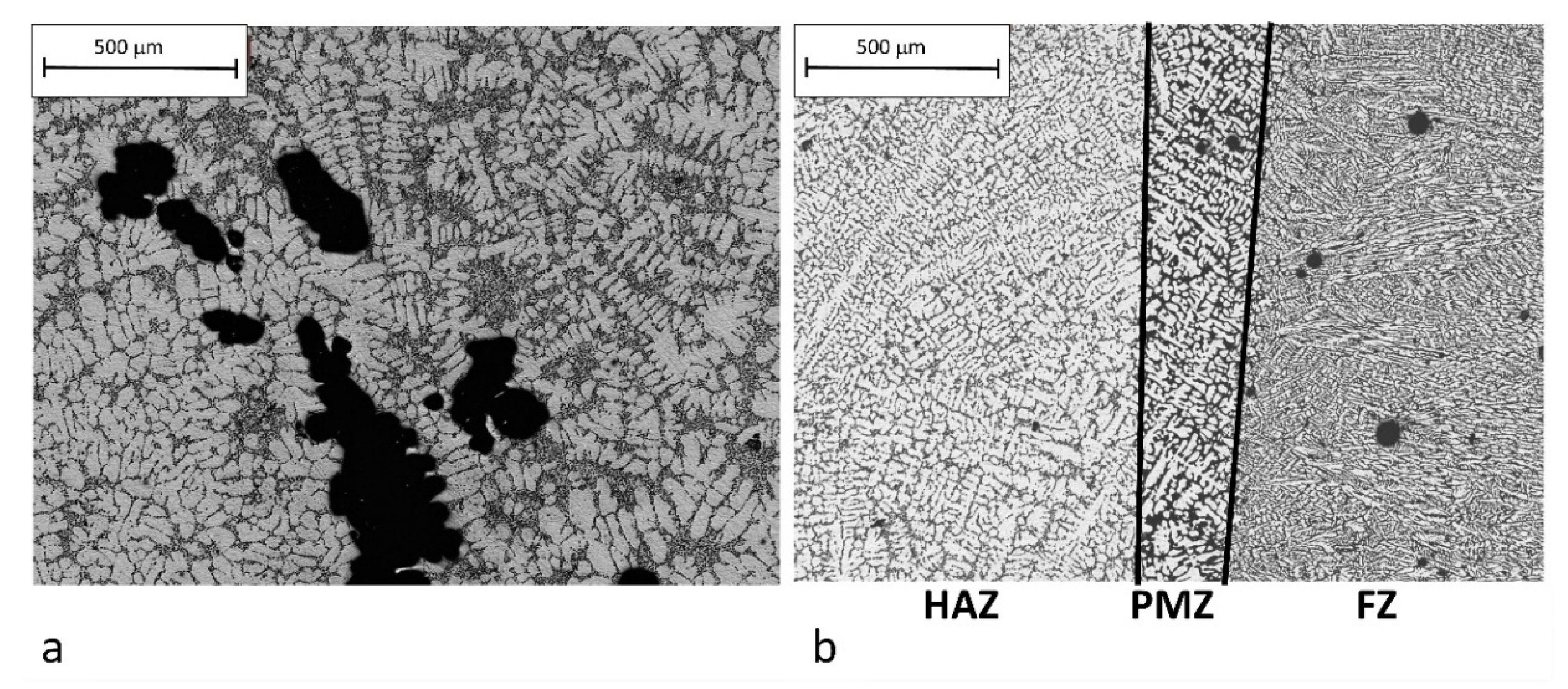
  • Re-solubilization area (PMZ): In the PMZ, the high temperature (T > 450 °C) induces a complete dissolution of hardening precipitates. During cooling, according to times and temperature reached, the re-precipitation of hardening compounds could be possible.
  • Intermediate area: The temperature exceeds 380 °C and the transformation of the equilibrium phase β takes place. Indeed, in this area, located at about 10 mm from the FZ, it is possible to observe the minimum hardness value.
  • Over-aging area: 380 < T (°C) < 240. In these zones, the increase in hardness could be justified with the transformation of β” in β’.
  • Slightly altered zone: Temperatures do not exceed 240 °C, thus any marked over-aging phenomena of β” can be avoided. In this area, the hardness value tends to be the base material, even if some hardness fluctuations are still present.

3.3.1. Frame Samples

The micro-hardness results obtained for the E-E and E-C samples are summarized in Figure 11 and Figure 12, respectively. Regarding the E-E sample, it can be observed that the FZ maintained a fairly constant hardness, around 60 HV, while there was first a hardness increase (about 90 HV) in the PMZ, followed by a decrease to 60 HV in the HAZ. Finally, the BM hardness was restored at about 20–25 mm from the fusion line for both the extrusion and casting interfaces. For the E-C sample, the HV profile of the extruded component showed a qualitative trend similar to the previous E-E analysis. In this case, however, the local minimum was approximately 80 HV; this suggests that during the welding process, the critical temperature of 380 °C was not reached, or not maintained long enough to complete the transformation of Mg2Si in the equilibrium phase β. The HAZ was only about 12 mm from the fusion line, confirming the possibility that in this case, the welding process was faster than in the previous one. For the cast component, the micro-hardness profile was similar to that of the extrusion, but showed that the plastic deformation aluminum alloy was more sensitive to the thermal cycle than the cast one.

3.3.2. Bar Samples

In Figure 13, Figure 14 and Figure 15, the macro and micro hardness results for the bar welded specimens are reported. Concerning the analysis of all samples, the HV profile in the MIG welded samples showed the strongest reduction of mechanical properties; the fiber laser-MIG hybrid welded samples showed the best behavior, while the CMT welded samples had intermediate characteristics. The use of UNI ER 4043 filler material, softer than EN AW 6082, certainly contributed to the mechanical properties, especially in the FZ. Regarding the E-E samples, the microhardness profiles confirmed the results and the interpretations obtained in the E-E frame case. In addition, a different behavior could be observed looking the macro-hardness HRF profiles. In this case, MIG and CMT had a very similar trend, with about 62 HRF in the FZ and little loss of hardness up to the HAZ, which was wider in the MIG technique case. For the laser technique, the weld area was the softest, there was a slight decrease at 5 mm, and the hardness finally tended to increase. These differences revealed in the FZ and PMZ are probably due to the diverse heat input from the MIG, CMT, and laser welding process on the external surface of the samples. Furthermore, the specimens were thinner compared to the frame sections. These considerations clarify why the heat exchange was greater in the bar surfaces, both with respect to the cross section of the same samples and to the joints of the frame. For the C-C joints, the micro-hardness profiles showed a clear definition of the BM, HAZ, and FZ. The trend was very similar for all techniques, but the hardness in the FZ center was very different, probably due to the presence of typical defects of the cast alloy used. Similar considerations can be advanced for hardness variations also observed in other areas of the samples. In the PMZ zone, the HV reached a hardness value of about 78–80 for MIG and CMT and 86 HV for the laser technique. In the HAZ, there was a slight drop of HV and afterward, the area far from the melt zone around 20 mm tended toward the stabilization in the HV value (50–55 HV for MIG and CMT, 80 HV for laser). The evolution of the macro-hardness HRF followed the trend already achieved in the case of the E-E combination. Noteworthy is the trend difference between CMT and MIG. Although the evolution was similar, the CMT welding showed a softer passage between the various zones. Once again, this fact is due to the different heat input during welding. It should be noted that MIG welding had drastic effects on the hardness, which reached values typical of an annealing. CMT welding had similar, but less pronounced effects. This could be caused by the high thermal input on thin samples, which caused an effect equivalent to an annealing treatment. This is probably also related to the high percentage of silicon (~7%) in this cast alloy, which entails a low material conductivity and a consequent difficult dissipation of the welding heat. On the other hand, during the laser technique, the heat input was highly localized in the FZ, thus this behavior was not observed.
Indeed, for the E-C coupling, the HV values confirmed the results of the tests conducted on the other two combinations and the E-C frame case studied. In particular, it was confirmed that the extruded component (Si~1%) better conducted the heat produced during welding, resulting in a reduced change in hardness [58,59,60]. Looking at the hardness profiles, considerations similar to E-E and E-C can be advanced for extrusion-welding and casting-welding interfaces, respectively. With regard to the HRF hardness test, the typical evolution was obtained, with an initial HRF peak in the PMZ, a subsequent decrease, and a gradual restoration of the properties as distance increased. It is worthwhile also noting that the HRF profile demonstrated the difference in heat exchange between the cast and extruded component during welding.

3.4. SEM Analysis

The PMZ and HAZ are crucial areas in weld alloys that are hardened by artificial aging. The transformation phase along the welding profiles was explained in the previous section. In addition, in the literature [55,56], it is documented that the microstructure of the welded Al–Si alloys is characterized by the presence of elongated particles (dimensions of about 1–10 μm) and extremely fine particles (size approximately of 0.1–0.5 μm) dispersed in a matrix with uniformly distributed micropores. This is remarkable, since it has been reported that Si-rich precipitates are found due to the excess silicon in the alloys. The larger particles were identified as the (Fe, Mn)3SiAl12 compound, while the finer ones were Mg2Si, the hardening phase obtained during thermal treatment (T6).
The structures of both EN AC 42100-T6 and 6000 series joints were revealed by the SEM/EDS investigations, as reported in Figure 16. The fusion zone had a chemical composition that was affected by the AA 4043 filler metal in addition to the welded materials. The chemical analysis of the white particles confirmed that these could be the compound (Fe, Mn)3SiAl12, with an average size about 3–5 μm. These particles were observed in both the extrusion and casting components, where the concentration was higher. The analysis of the PMZ highlights that the fiber laser-MIG hybrid samples had the highest presence of these particles with a finer morphology, while for the MIG and CMT techniques, the amount and dimensions were very similar.

4. Conclusions

The present paper studied different welding techniques applied to hybrid aluminum alloys (EN AW-6181 T6 and EN AC-42100 T6) joined each other in all possible combinations. First, a real case study was analyzed, which consisted of a sports-car frame where the cast EN AC-42100 T6 and EN AW-6082 T6 aluminum alloys were welded with the traditional MIG technique. The MIG, CMT, and fiber laser-MIG hybrid joints of EN AW-6181 T6 and EN AC-42100 T6 bars were studied to extend the study to other techniques that are difficult to find in real applications and compare the results in a more reliable way in simpler and more reproducible geometries. The microstructure and hardness properties were evaluated and the main conclusions can be summarized as follows:
  • From a quality point of view, the typical defects of welded aluminum alloys such as porosity and the incomplete penetration were observed mainly in the frame welds. Then, cracks were noticed only in the frame joints, most likely due to a greater difficulty in heat dissipation for higher thicknesses and more complex geometries. In addition, typical casting defects, mainly shrinkage cavities, were found.
  • Regarding the macrostructures, a greater quality was observed for the fiber laser joint. Then, the FZ, PMZ, and HAZ microstructures were observed. All joints had similar FZ microstructures, with the weld seam characterized by fine dendrites. The chemical composition of the fusion zone was affected by the addition of UNI ER 4043 filler. The PMZ was even observed at low magnification and its width was greater in the C-C case. In general, the innovative techniques (CMT and fiber laser hybrid) allow a better microstructure to be obtained than the traditional technique (MIG).
  • Hardness tests (HRF and micro-HV) demonstrated that the mechanical characteristics of the PMZ and HAZ were better for the innovative techniques due to reduced changes in their microstructure when compared to the MIG technique. In particular, the fiber laser-MIG hybrid technique showed the best behavior, and the CMT welded samples had intermediate characteristics. Considering the relationship between the local temperature peaks reached during the welding process and the hardness value obtained, four HAZ subzones were identified:
    -
    Re-solubilization area (PMZ, T > 450 °C) with a complete dissolution of hardening precipitates and subsequent re-precipitation related to cooling parameters;
    -
    Intermediate area (about 10 mm from FZ, T > 380 °C) where the β transformation takes place;
    -
    Over-aging area: (380 < T (°C) < 240) with the β” to β’ transformation; and
    -
    Slightly altered zone (T < 240 °C) where any marked over-aging phenomena of β” are avoided.
  • The best behavior was observed, as expected, for the E-E samples, while the worst results were observed for the C-C combination, especially in the MIG welding, where the hardness values were typical of an annealing. This could be caused by both the high thermal input on thin samples and the high percentage of silicon (~7%) in this cast alloy (low material conductivity and difficult welding heat dissipation). Finally, the E-C coupling showed intermediate properties.
It can be concluded that the present study demonstrated the higher quality of innovative CMT and fiber laser-MIG hybrid welding over the traditional MIG, either in terms of metallurgical or mechanical properties. The properties achieved during these experiments could be useful information during the design of real automotive applications due to the increasing demand of highly loaded and lightened structures. Thus, there will be an increasing need for thinner and hybrid combinations of Al alloys that can be addressed by looking at the present database of CMT or laser-MIG hybrid welding results. In addition, the comparison between casting and extrusion techniques provided some input for future development in this field, which, for example, would require better thermal management of the welding input in order to increase the casting welding quality.

Author Contributions

Conceptualization, G.C., S.C.; Investigation, G.C., S.C.; Methodology, G.C., S.C.; Supervision G.C., S.C.; Writing—original draft, G.C.; Writing—review & editing S.C. All authors have read and agreed to the published version of the manuscript.

Acknowledgments

The authors are grateful to Ing. Enrico Lena, Ing Stefano Manesta, and Ing. Andrea Panvini for their collaboration in carrying out the experiments.

Conflicts of Interest

The authors declare no conflicts of interest.

References

  1. Miller, W.S.; Zhuang, L.; Bottema, J.; Wittebrood, A.J.; De Smet, P.; Haszler, A.; Vieregge, A. Recent development in aluminium alloys for the automotive industry. Mater. Sci. Eng. A 2000, 280, 37–49. [Google Scholar] [CrossRef]
  2. Cecchel, S.; Cornacchia, G.; Gelfi, M.A. A study of a non-conventional evaluation of results from salt spray test of aluminum High Pressure Die Casting alloys for automotive components. Mater. Corros. 2019, 70, 70–78. [Google Scholar] [CrossRef] [Green Version]
  3. Heinz, A.; Haszler, A.; Keidel, C.; Moldenhauer, S.; Benedictus, R.; Miller, W.S. Recent development in aluminium alloys for aerospace applications. Mater. Sci. Eng. A 2000, 280, 102–107. [Google Scholar] [CrossRef]
  4. ASM Specialty Handbook. Aluminum and Aluminum Alloys; Davis, J.R., Ed.; ASM International: Geauga, OH, USA, 1993; ISBN 978-0-87170-496-2. [Google Scholar]
  5. Chindamo, D.; Lenzo, B.; Gadola, M. On the vehicle sideslip angle estimation: A literature review of methods, models and innovations. Appl. Sci. 2018, 8, 355. [Google Scholar] [CrossRef] [Green Version]
  6. Hirsch, J. Aluminium in Innovative Light-Weight Car Design. Mater. Trans. 2011, 52, 818–824. [Google Scholar] [CrossRef] [Green Version]
  7. European Commission. Proposal for a Regulation of the European Parliament and of the Council Amending Regulation (EC) No 443/2009 to Define the Modalities for Reaching the 2020 Target to Reduce CO2 Emissions from New Passenger Cars and Proposal for a Regulation of the European Parliament and of the Council Amending Regulation (EU) No 510/2011 to Define the Modalities for Reaching the 2020 Target to Reduce CO2 Emissions from new Light Commercial Vehicles, (European Commission, 2012). Available online: http://eur-lex.europa.eu/resource.html?uri=cellar:70f46993-3c49-4b61ba277319c424cbd.0001.02/DOC_1&format=PDF (accessed on 11 December 2019).
  8. Helms, H.; Lambrecht, U. The potential contribution of light-weighting to reduce transport energy consumption. Int. J. Life Cycle Assess 2007, 12, 58–64. [Google Scholar]
  9. Cecchel, S.; Ferrario, D.; Panvini, A.; Cornacchia, G. Lightweight of a cross beam for commercial vehicles: Development, testing and validation. Mater. Des. 2018, 149, 122–134. [Google Scholar] [CrossRef]
  10. Kim, H.C.; Wallington, T.J. Life-Cycle Energy and Greenhouse Gas Emission Bene fits of Lightweighting in Automobiles: Review and Harmonization. Environ. Sci. Technol. 2013, 47, 6089–6097. [Google Scholar] [CrossRef]
  11. ASM Metals Handbook. Welding, Brazing and Soldering, 10th ed.; American Society for Metals: Geauga, OH, USA, 1993; Volume 6. [Google Scholar]
  12. Cornacchia, G.; Cecchel, S.; Panvini, A. A comparative study of mechanical properties of metal inert gas (MIG)-cold metal transfer (CMT) and fiber laser-MIG hybrid welds for 6005A T6 extruded sheet. Int. J. Adv. Manuf. Technol. 2017, 94, 2017–2030. [Google Scholar] [CrossRef]
  13. Apelian, D.; Shivkumar, S.; Sigworth, G. Fundamental Aspects of heat treatment of cast Al−Si−Mg alloys. AFS Trans. 1989, 97, 727–742. [Google Scholar]
  14. Faccoli, M.; Dioni, D.; Cecchel, S.; Cornacchia, G.; Panvini, A. An experimental study to optimize the heat treatment of gravity cast Sr-modified B356 aluminum alloy. Trans. Nonferrous Met. Soc. China 2017, 27, 1698–1706. [Google Scholar] [CrossRef]
  15. Lados, D.A.; Apelian, D.; Wan, L. Solution treatment effects on microstructure and mechanical properties of Al−(1 to 13 pct)Si−Mg cast alloys. Metall. Mater. Trans. B 2011, 42, 171–180. [Google Scholar] [CrossRef] [Green Version]
  16. Dioni, D.; Cecchel, S.; Cornacchia, G.; Faccoli, M.; Panvini, A. Effects of artificial aging conditions on mechanical properties of gravity cast B356 aluminum alloy. Trans. Nonferrous Met. Soc. China 2015, 25, 1035–1042. [Google Scholar] [CrossRef]
  17. Morita, A. Aluminium alloys for automobile applications. In Proceedings of the ICAA-6, Toyohashi, Japan, 5–10 July 1998; Volume 1, pp. 25–32. [Google Scholar]
  18. Andersen, S.J.; Zandbergen, H.W.; Jansen, J.; Traeholt, C.; Tundal, U.; Reiso, O. “The crystal structure of the β’’ phase in al-mg-si alloys. Acta Mater. 1998, 46, 3283–3298. [Google Scholar] [CrossRef]
  19. Ikeno, K.M.S.; Sato, T. Hrtem Study of Nano-Precipitation Phases in 6000 Series Aluminum Alloys. Sci. Technol. Educ. Microsc. An Overv. 2003, 152–162. [Google Scholar]
  20. Maisonnette, D.; Suery, M.; Nelias, D.; Chaudet, P.; Epicier, T. Effects of heat treatments on the microstructure and mechanical properties of a 6061 aluminium alloy. Mater. Sci. Eng. A Struct. Mater. 2011, 528, 2718–2724. [Google Scholar] [CrossRef] [Green Version]
  21. International Aluminium Institute. Primary Aluminium Production. 22/09/08. 2008. Available online: http://www.world-aluminium.org (accessed on 10 December 2019).
  22. Voisin, P. Métallurgie extractive de l’aluminium. Techniques de l’ingénieur. Matér. Mét. 1992, 2340, 2340. [Google Scholar]
  23. Liu, L.; Ren, D.; Liu, F. A Review of Dissimilar Welding Techniques for Magnesium Alloys to Aluminum Alloys. Materials 2014, 7, 3735–3757. [Google Scholar] [CrossRef] [Green Version]
  24. Cao, X.; Jahazi, M.; Immarigeon, J.P.; Wallace, W. A review of laser welding techniques for magnesium alloys. J. Mater. Process. Technol. 2006, 171, 188–204. [Google Scholar] [CrossRef]
  25. Abioye, T.E.; Olugbade, T.O.; Ogedengbe, T.I. Welding of Dissimilar Metals Using Gas Metal Arc and Laser Welding Techniques: A Review. J. Emerg. Trends Eng. Appl. Sci. 2017, 8, 225–228. [Google Scholar]
  26. Fang, Y.; Jiang, X.; Mo, D.; Zhu, D.; Luo, Z. A review on dissimilar metals’ welding methods and mechanisms with interlayer. Int. J. Adv. Manuf. Technol. 2019, 102, 2845–2863. [Google Scholar] [CrossRef]
  27. Song, Y.; Yang, X.; Cui, L.; Hou, X.; Shen, Z.; Xu, Y. Defect features and mechanical properties of friction stir lap welded dissimilar AA2024–AA7075 aluminum alloy sheets. Mater. Des. 2014, 55, 9–18. [Google Scholar] [CrossRef]
  28. Lean, P.P.; Gil, L.; Urena, A. Dissimilar welds between unreinforced AA6082 and AA6092/SiC/25p composite by pulsed-MIG arc welding using unreinforced filler alloys (Al–5Mg and Al–5Si). J. Mater. Process. Technol. 2003, 143–144, 846–850. [Google Scholar] [CrossRef]
  29. Palanivel, R.; Mathews, P.K.; Dinaharan, I.; Murugan, N. Mechanical and metallurgical properties of dissimilar friction stir welded AA5083-H111 and AA6351-T6 aluminum alloys. Trans. Nonferrous Met. Soc. China 2014, 24, 58–65. [Google Scholar] [CrossRef]
  30. Gungor, B.; Kaluc, E.; Taban, E.; Aydin, S.I.K. Mechanical and microstructural properties of robotic Cold Metal Transfer (CMT) welded 5083-H111 and 6082-T651 aluminum alloys. Mater. Des. 2014, 54, 207–211. [Google Scholar] [CrossRef]
  31. Jonckheere, C.; de Meester, B.; Denquin, A.; Simar, A. Torque, temperature and hardening precipitation evolution in dissimilar friction stir welds between 6061-T6 and 2014-T6 aluminum alloys. J. Mater. Process. Technol. 2013, 213, 826–837. [Google Scholar] [CrossRef]
  32. Ilangovan, M.; Boopathy, S.R.; Balasubramanian, V. Microstructure and tensile properties of friction stir welded dissimilar AA6061–AA5086 aluminium alloy joints. Trans. Nonferrous Met. Soc. China 2015, 25, 1080–1090. [Google Scholar] [CrossRef]
  33. Uematsu, Y.; Tozaki, Y.; Tokaji, K.; Nakamura, M. Fatigue behavior of dissimilar friction stir welds between cast and wrought aluminum alloys. Strength Mater. 2007, 40, 138–141. [Google Scholar] [CrossRef]
  34. Ghosh, M.; Husain, M.M.; Kumar, K.; Kailas, S.V. Friction stir-welded dissimilar aluminum alloys: Microstructure, mechanical properties, and physical state. J. Mater. Eng. Perform. 2013, 22, 3890–3901. [Google Scholar] [CrossRef]
  35. Wang, M.; Zou, Y.D.; Hu, H.; Meng, G.; Cheng, P.; Chu, Y.L. Tensile properties and microstructure of joined vacuum die cast aluminum alloy A356 (T6) and wrought alloy 6061. Adv. Mater. Res. 2014, 939, 90–97. [Google Scholar] [CrossRef]
  36. Nie, F.; Dong, H.; Chen, S.; Li, P.; Wang, L.; Zhao, Z.; Li, X.; Zhang, H. Microstructure and Mechanical Properties of Pulse MIG Welded 6061/A356 Aluminum Alloy Dissimilar Butt Joints. J. Mater. Sci. Technol. 2018, 34, 551–560. [Google Scholar] [CrossRef]
  37. Casalino, G.; Leo, P.; Mortello, M.; Perulli, P.; Varone, A. Effects of Laser Offset and HybridWelding on Microstructure and IMC in Fe–Al DissimilarWelding. Metals 2017, 7, 282. [Google Scholar] [CrossRef] [Green Version]
  38. Wang, Z.; Oliveira, J.P.; Zeng, Z.; Bu, X.; Peng, B.; Shao, X. Laser beam oscillating welding of 5A06 aluminum alloys: Microstructure, porosity and mechanical properties. Opt. Laser Technol. 2019, 11, 58–65. [Google Scholar] [CrossRef]
  39. Manti, R.; Dwivedi, D.K.; Agarwal, A. Microstructure and hardness of AlMg-Si weldments produced by pulse GTA welding. Int. J. Adv. Manuf. Technol. 2008, 36, 263–269. [Google Scholar] [CrossRef]
  40. Feng, J.; Zhang, H.; He, P. The CMT short-circuiting metal transfer process and its use in thin aluminium sheets welding. Mater. Des. 2009, 30, 1850–1852. [Google Scholar] [CrossRef]
  41. Zapico, E.P.; Lutey, A.H.; Ascari, A.; Pérez, C.R.G.; Liverani, E.; Fortunato, A. An improved model for cold metal transfer welding of aluminium alloys. J. Therm. Anal. Calorim. 2018, 131, 3003–3009. [Google Scholar] [CrossRef]
  42. Wang, J.; Feng, J.C.; Wan, Y.X. Microstructure of Al–Mg dissimilar weld made by cold metal transfer MIG welding. J. Mater. Sci. Technol. 2008, 24, 827–831. [Google Scholar] [CrossRef]
  43. Pickin, C.G.; Young, K. Evaluation of cold metal transfer (CMT) process for welding aluminium alloy. J. Sci. Technol. Weld. Join. 2006, 11, 583–585. [Google Scholar] [CrossRef]
  44. Katayamaa, S.; Kawahitoa, Y.; Mizutania, M. Elucidation of laser welding phenomena and factors affecting weld penetration and welding defects. Phys. Procedia 2010, 5, 9–17. [Google Scholar] [CrossRef] [Green Version]
  45. Katayama, S.; Nagayama, H.; Kawahito, Y. Fiber laser welding of aluminium alloy. J. Weld. Int. 2009, 23, 744–752. [Google Scholar] [CrossRef]
  46. Kuryntsev, S.V.; Gilmutdinov, A.K. The effect of laser beam wobbling mode in welding process for structural steels. Int. J. Adv. Manuf. Technol. 2015, 81, 1683–1691. [Google Scholar] [CrossRef]
  47. Aalderink, B.J.; Pathiraj, B. Seam gap bridging of laser based processes for the welding of aluminium sheets for industrial applications. Int. J. Adv. Manuf. Technol. 2010, 48, 143–154. [Google Scholar] [CrossRef]
  48. Hayashi, T.; Matsubayashi, K.; Katayama, S.; Abe, N.; Matsunawa, A.; Ohmori, A. Reduction mechanism of porosity in tandem twin-spot laser welding of stainless steel. Weld. Int. 2003, 17, 12–19. [Google Scholar] [CrossRef]
  49. Yangchun, Y.; Wang, C.; Xiyuan, H.; Wang, J.; Shengfu, Y. Porosity in fiber laser formation of 5A06 aluminum alloy. J. Mech. Sci. Technol. 2010, 24, 1077–1082. [Google Scholar]
  50. Chowdhury, S.H.; Chen, D.L.; Bhole, S.D.; Powidajko, E.; Weckman, D.C.; Zhou, Y. Fiber laser welded AZ31 magnesium alloy: The effect of welding speed on microstructure and mechanical properties. Metall. Mater. Trans. A 2012, 43, 2133–2147. [Google Scholar] [CrossRef]
  51. ASTM International. ASTM E18–03 (2003) Standard Test Methods for Rockwell Hardness and Rockwell Superficial Hardness of Metallic Materials; ASTM International: West Conshohocken, PA, USA, 2003. [Google Scholar]
  52. ASTM International. ASTM E92–160 (2016) Standard Test Methods for Vickers Hardness and Knoop Hardness of Metallic Materials; ASTM International: West Conshohocken, PA, USA, 2016. [Google Scholar]
  53. ASTM International. ASTM E140–02 (2002) Standard Hardness Conversion Tables for Metals Relationship among Brinell Hardness, Vickers Hardness, Rockwell Hardness, Superficial Hardness, Knop Hardness, and Scleroscope Hardness; ASTM International: West Conshohocken, PA, USA, 2002. [Google Scholar]
  54. EN AW-6082, Metra. Available online: http://www.metra.it/aluminium/tabellaLeghe/tabellaCatalogo6082.pdf (accessed on 8 October 2019).
  55. Hwang, L.; Gung, C.; Shih, T. A study on the qualities of GTA-welded squeeze-cast A356 alloy. J. Mater. Process. Technol. 2001, 116, 101–113. [Google Scholar] [CrossRef]
  56. Missori, S.; Montanari, R.; Sili, A. Caratterizzazione meccanica mediante prove fimec di giunti saldati in lega di Al 6082. La Metall. Ital. 2001, 3, 35–39. [Google Scholar]
  57. Myhr, O.R.; Grong, O.; Fjaer, H.G.; Marioara, C.D. Modelling of the microstructure and strength evolution in Al–Mg–Si alloys during multistage thermal processing. Acta Mat. 2004, 52, 4997–5008. [Google Scholar] [CrossRef]
  58. Tang, N.-K.; Chen, J.K.; Hung, H.-Y. Effect of silicon on thermal conductivity of Al-Si alloys. In Proceedings of the Materials Science and Technology Conference and Exhibition 2013, (MS&T’13), Montreal, PQ, Canada, 27–31 October 2013. [Google Scholar]
  59. Zhilin, A.S.; Jianguo, L.; Yalunina, V.R.; Varlamenko, D.S.; Bykov, V.A.; Derevjankin, E.V. Influence of Silicon on Thermal Conductivity at Room Temperature of Al–Si–Fe Alloys. KnE Eng. 2018, 3, 294–297. [Google Scholar] [CrossRef]
  60. Stadler, F.; Antrekowitsch, H.; Werner, F.; Kaufmann, H.; Riccardo, P.E.; Peter, U. The effect of main alloying elements on the physical properties of Al-Si foundry alloys. Mater. Sci. Eng. A 2013, 560, 481–491. [Google Scholar] [CrossRef]
Figure 1. Samples obtained from the sub-frames: (a) extruded (6082-T6)-extruded (6082-T6) welds, (b) extruded (6082-T6)-cast (EN AC 42100-T6) welds.
Metals 10 00441 g001
Figure 2. Example of the samples used for the different weld techniques.
Metals 10 00441 g002
Figure 3. Defects and microstructures of metal inert gas (MIG) frame joints. E-E combination.
Metals 10 00441 g003
Figure 4. Defects and microstructures of MIG frame joints. E-C combination.
Metals 10 00441 g004
Figure 5. Weld geometry and defects of MIG, CMT (cold metal transfer), and fiber laser-MIG hybrid joints.
Metals 10 00441 g005
Figure 6. (a) Microstructure of the 6082-T6 alloy, BM. Keller etch, 500×; (b) Microstructure of 6181-T6 alloy, BM. Keller etch, 100×.
Metals 10 00441 g006
Figure 7. (a) Microstructure of the EN AC 42100-T6 alloy, 50×; (b) Microstructure present at the fusion zone (FZ)/cast component interface, 50×.
Metals 10 00441 g007
Figure 8. Macrostructures of the interface between the HAZ (heat-affected zone), PMZ (partially molten zone), and FZ (fusion zone) in the Cast-Cast combination (C-C), Keller etch, 50×.
Metals 10 00441 g008
Figure 9. Macrostructures of the interface between the HAZ, PMZ, and FZ in the Extruded-Extruded (E-E) combination, Keller etch, 50×.
Metals 10 00441 g009
Figure 10. Macrostructures of the interface between the HAZ, PMZ, and FZ in the Extruded-Cast combination (E-C), Keller etch, 50×.
Metals 10 00441 g010
Figure 11. Evolution of the micro-hardness HV (hardness Vickers) in the E-E sub-frame combination as a function of the position along a transverse section of the weld (MIG joint).
Metals 10 00441 g011
Figure 12. Evolution of the micro-hardness HV in the E-C sub-frame combination as a function of the position along a transverse section of the weld (MIG joint).
Metals 10 00441 g012
Figure 13. Evolution of the macro-hardness HRF and micro-hardness HV in the E-E combination of the weld for laser, CMT, and MIG.
Metals 10 00441 g013
Figure 14. Evolution of the macro-hardness HRF and micro-hardness HV in the C-C combination of the weld for laser, CMT, and MIG.
Metals 10 00441 g014
Figure 15. Evolution of the macro-hardness HRF and micro-hardness HV in the E-C combination of the weld for laser, CMT, and MIG.
Metals 10 00441 g015
Figure 16. Some examples of the precipitate types in the PMZ: chemical composition in wt%.
Metals 10 00441 g016
Table 1. Chemical composition of aluminum alloys.
AlloySiFeCuMnMgCrZnTiTotal Others El.Al
EN AW-61810.8–1.200.450.100.150.60–1.00.100.200.100.15Bal.
EN AW-60820.7–1.3<0.50<0.100.4–1.00.60–1.2<0.25<0.200.10<0.05Bal.
EN AC-421006.50–7.50<0.60<0.25<0.350.20–0.45-<0.35<0.250.15Bal.
UNI – ER 40434.5–4.60.80.30.0050.05-0.1--Bal.

