The Effect of Honing Angle and Roughness Height on the Tribological Performance of CuNiCr Iron Liner


1
Department of materials science and engineering, Dalian Maritime University, Dalian 116026, China
2
Key Lab of Ship-Maintenance & Manufacture, Dalian Maritime University, Dalian 116026, China
*
Authors to whom correspondence should be addressed.
Metals 2019, 9(5), 487; https://doi.org/10.3390/met9050487
Submission received: 3 April 2019
/
Revised: 16 April 2019
/
Accepted: 24 April 2019
/
Published: 26 April 2019
Abstract
:This work investigated the effect of honing morphologies of CuNiCr iron liner on its tribological properties sliding against the Cr-Al2O3 coated piston ring. The worn surface morphology and elements distribution as well as the wear behaviors of CuNiCr iron liner were analyzed to explore the influencing of the honing angle and roughness height on the friction and wear resistance. The results show that the optimized honing angle and roughness can improve the tribological performance of the iron liner, and different tribological characteristics are closely related to different roughness parameters. The wear process of the CuNiCr iron liner against Cr-Al2O3 coated piston rings in sequence was platform flattening, plastic flow, growth of the flakes on the platform edge and flakes debonding. For the smooth surface, the plastic deformed flakes were much fewer due to the low height of the platforms, thus the grooves were not fully filled and there was a slight effect of the debonded debris on the friction pair.
1. Introduction
Diesel engine is one of the widely used internal combustion engines. With the increasing power density, the key friction pair piston ring and cylinder liner (PRCL) will suffer more thermal and mechanical load which may result in the higher friction loss and faster degradation of PRCL. To improve the tribological performance of the PRCL interface, changing the inner surface morphology of iron liner is an applicable option.
Generally, the low surface roughness of iron liner is beneficial to reduce the friction loss due to the lower direct contact chance among the asperities [1,2,3]. However, this mirror-like surface has no designed structure to store lubricating oil. Thus, the direct contact area on the PRCL interface will apparently increase, resulting in the worse tribological performance of PRCL, especially under the heavy-duty condition. In the process of optimizing the geometrical structure of a cylinder liner, surface texturing, which is the privilege surface processing method, has been widely accepted [4,5,6]. As one of the earliest surface textured methods, plateau-honed texture is still a commonly used surface modifying method. Compared with traditional non-honed cylinder liner, plateau-honed texture is an effective way to reduce the frictional losses and lubrication oil consumption [7,8]. Moreover, it can produce a substantially flat or plateau finish on the working surface with much larger bearing area, while maintaining a cross-hatch pattern of valleys for oil retention [9,10]. When the diesel engine works, these special structures can play an important role on lubricating oil reserve and lubricating oil film formation [11,12,13]. In addition, Joshi GS experimentally found that the rougher honing surface resulted in the increase of oil film thickness [14]. Shen et al. reported that the performance of honing pattern was strongly dependent on the orientation [15]. However, few studies documented how the honing angle and roughness height affect the scuffing behavior and the underlying mechanisms, especially for the heavy-duty conditions.
The investigation on the tribological performance of PRCL cannot isolate the mating materials. Kim et al. conducted the reciprocating wear tests using the steel balls as counter surface instead of piston ring for wear tests [16]. Mezghani et al. simulated the influence of honing grooves for the iron-ball contact [17]. Although their results are valuable in studying the effect of honing morphology on the friction performance of cylinder liner, more reliable results should be obtained on a suitable testing device with actual liner and piston rings.
This work aimed to study the effect of honing angle and roughness height on wear and scuffing resistance performance of CuNiCr iron liner based on the wear tests and scuffing resistance tests. One of the important innovations of the present study was the use of purposely designed testing device, which enabled the evaluation of the tribological performance of the cylinder liner and piston ring friction pair under the boundary and mixed lubrication. On the other hand, the roughness of the cylinder liner was characterized by the honing peak height (Rpk), core roughness depth (Rk) and valley height (Rvk), rather than conventionally used roughness average (Ra), and the correlation of these parameters with the friction force and wear depth as well as the anti-scuffing capacity was investigated. Finally, the wear behavior of the CuNiCr iron liner mating with the Cr-Al2O3 coated piston ring was related with the worn surface morphologies to explore the wear mechanisms of the friction pair.
2. Materials and Methods
2.1. Materials
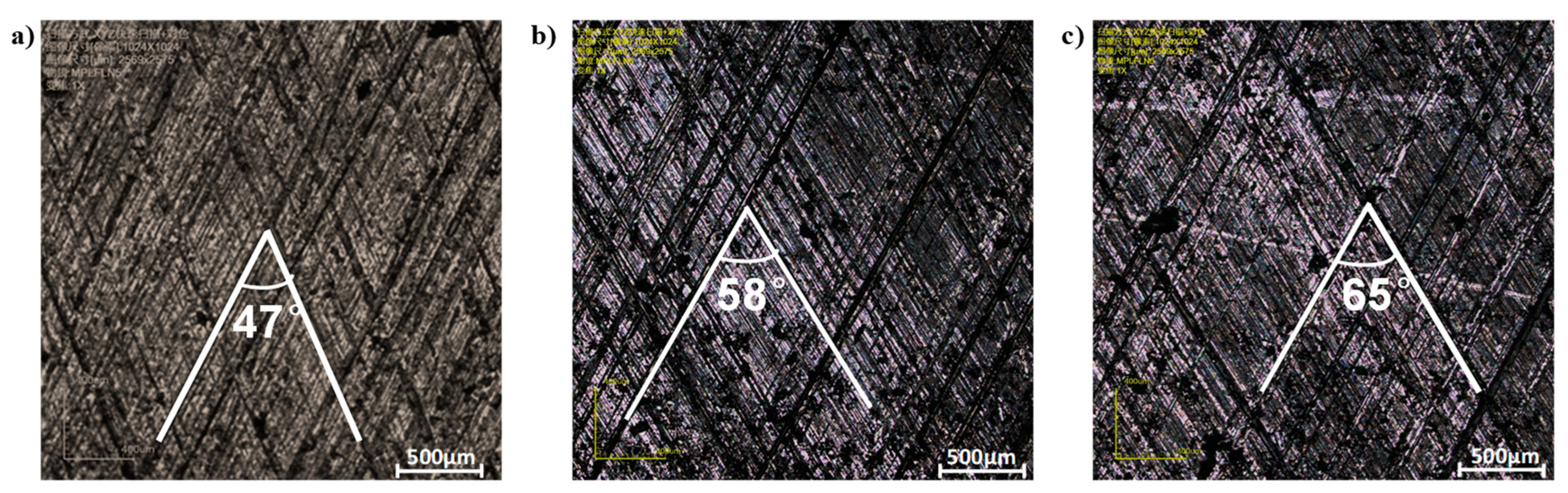
Actual CuNiCr iron liners were selected, and cut for the wear tests by electrical discharge machining (Wire electric discharge digital control machine tool-DK7740, Taizhou CNC machine tool company, Taizhou, China). The inner surface of the iron liner was treated by different honing process to generate the different roughness and cross-hatch orientations. The strategy of honing processing included: (a) a rough honing performed with large grain size abrasive stones; and (b) a fine honing process to remove the surface peaks. The iron cylinder liners with almost the same roughness average (Ra = 1.29 μm) but different cross-hatch angles of 47°, 58° and 65° were selected, as shown in Figure 1. The internal diameter of the iron specimen was 270 mm, and the wall thickness was 10 mm. The chemical composition is shown in Table 1. Each iron liner was cut into specimens with the central angle of 3° and length of 43 mm. The matrix material was grey cast iron and a typical metallographic image presenting the lamellar pearlite and graphite as well as a small amount of phosphorus eutectic is illustrated in Figure 2.
Another four iron liners with the same honing cross-hatch angle (about 58°) but different Ra (0.70 μm, 0.85 μm, 0.98 μm and 1.25 μm) were also used to evaluate the effect of the surface roughness height on the tribological performance of the iron liner.
As shown in Figure 3, an alloy cast iron piston ring coated with Cr-Al2O3 layer, which is usually called CKS piston ring, was used as the counterpart materials. The matrix material of piston ring was ductile iron with the metallographic structure of acicular martensite (see Figure 3a). The external diameter of the ring was 270 mm, which was identical to the internal diameter of the cylinder liner, resulting in the perfect matching of the friction pair. The piston ring was carefully machined into 30 equal parts with the central angle of 12°. The Al2O3 particles with a diameter of ~2 μm were embedded in the cracks of the chromium coating, as shown in Figure 3b. Machining marks along the circumferential direction of the piston ring also appeared on the surface. As shown in Figure 3c, the thickness of Cr-Al2O3 coating was about 276 μm. The Ra and hardness of the Cr-Al2O3 coating were 0.2 μm and 976.5 HV0.03, respectively.
CD40 diesel oil showing good oxidation and wear resistance was selected as the lubricant. The commercial lubricant had a viscous index of 39. Before each test, all specimens were cleaned by alcohol and gasoline to remove the surface impurities. After each test, the tested specimens were cleaned again by acetone to remove the residual oil and other debris for the surface observation and wear loss measurement.
2.2. Tribo-Testers and Test Detail
The maximum combustion gas pressure and the temperature are usually achieved when the piston is nearly at the top dead center (TDC) of the cylinder liner [18,19,20,21], where the sliding speed between PRCL is close to zero and almost no lubricating oil film can be formed. When the piston is approaching and departing the TDC, the sliding speed is low as well, usually causing the mixed lubrication even the boundary lubrication. Thus, the areas near and at the TDC are usually subjected the higher wear rate and higher possibility of the scuffing. Therefore, the wear behavior of the PRCL under the working condition at the TDC and its vicinities determines the tribo-performance and the reliability of the PRCL to a great certain extend. To simulate the actual condition near the TDC, a reciprocating sliding tribo-tester was designed, as shown in Figure 4. The tester had a fixed stroke of 30 mm, and allowed for precise control of the normal load (1 N–10 kN), speed (0.01–1 m/s) and temperature (30–300 °C). In the tribo-system, the stationary piston ring specimen vertically pressed at a required load on the iron liner specimen, which was reciprocating at a defined speed. Beneath the iron liner, the heater provided the required temperature for the test. Thus, the working condition of the developed tribo-device could be the same as or more intense than that of the actual PRCL. The friction coefficient was recorded to identify the friction properties of the liners with different inner surface morphology. The Ra measurements for both piston ring and cylinder liner were carried out using a surface profiler (Hommel tester-T6000 surface profiler, Hommel, Germany) and confocal laser scanning microscopy (CLSM, Olympus LEXT OLS4000, Olympus, Tokyo, Japan) [22,23]. Furthermore, more information regarding to the roughness height (Rpk, Rk, and Rvk) and worn depth of the tested specimens was measured by CLSM [24,25,26]. The worn depth of the tested piston ring and cylinder liner specimens was used to characterize the wear loss of the piston ring and cylinder liner, as shown in Figure 5. Before and after each wear test, the surface morphologies and composition of iron liner specimens and piston ring specimens were examined by scanning electron microscopy (SEM, ZEISS-SUPRA 55 SAPPHIRE, Oberkochen, Germany) and energy dispersive X-ray spectrometry (EDS, Oxford Instruments, Oxford, UK). At least five tests for each friction pair were conducted under the same conditions.
Wear and scuffing tests were performed using the in-house developed reciprocating tribo-tester. Unlike the traditional stepwise load increase based scuffing test, the lubricating oil supply was cut after a period of lubricated wear, and then the time interval between the oil cut-off and the onset of the scuffing was recorded to evaluate the scuffing resistance in this study. The typical friction force of the wear and scuffing tests is shown in Figure 6, where the testing parameters are also presented.
3. Results and Discussion
3.1. Effect of Honing Cross-Hatch Angle on the Tribological Performance of the CuNiCr Iron Liner
Figure 7 shows the average dead points friction coefficient, wear loss of iron liner and piston ring specimens with the different honing cross-hatch angles. The worn depth and friction coefficient of PRCL first decreased and then increased with the increasing of honing cross-hatch angles (from 47° to 65°). These wear results suggest that the optimized honing cross-hatch angle would result in the improved wear resistance capacity of the iron liner. Based on the variation trend in Figure 7, the best honing cross-hatch angle for CuNiCr iron liners was expected to be around 58° with the respect of good tribological performance.
Figure 8a shows the schematic of the piston ring specimen sliding against the cylinder liner surface in a typical reciprocation cycle of the developed tribo-device, and the friction forces with different honing cross-hatch angles a cycle are shown Figure 8b. In a typical cycle, there was no lubrication film formed at the dead points (Point 1, 3, 4 and 6) due to the zero velocity, as presented in Figure 8a, thus the asperities of the friction pair beared the load, and the boundary lubrication caused the maximum friction force (see Figure 8b). In contrast, the sliding speed was much higher in the middle of the stroke, and the oil film was prone to be formed and carry some load. Most likely, the friction pair worked under the mixed lubrication state, thus the friction force was comparatively low. On the other hand, the shape of the piston ring significantly affected the oil wedge as well. As the asymmetrical barrel surface piston ring was used in the tests, the formation of lubrication film differed with the sliding directions. When the wide side of the ring specimen was facing the sliding direction (see Point 2), an oil film could naturally form. On the contrary, when the ring was moving in the opposite direction, the narrow side of the ring specimen was scratching the oil, thus the oil wedge was much smaller (see Point 5).
As shown in Figure 8b, the friction force varied with honing cross-hatch angle, and 58° showed the lowest friction force in the whole cycle. This was because, with the decrease of honing cross-hatch angle (from 65° to 58°), the direction of honing groove distribution tended to be perpendicular to the sliding direction. The honing orientation could form a better blocking effect on the lubrication oil flow during the sliding process of the friction pair, which contributed to the loading beading capacity of the oil wedge. However, the maximum real area of contact between PRCL increased when the cross-hatch angle was too small, e.g. 47°; in this case, the chance of severe wear would increase accordingly [27]. Thus, the friction force first decreased and then increased with the decrease of the cross-hatch angle. The results and analyses suggest that changing the honing cross-hatch angle would result in the improved tribological performance, and about 58° was considered to be a beneficial value.
3.2. Effect of Honing Surface Roughness Height on the Tribological Performance of the Iron Liner
After honing, many deep and shallow grooves with the platform reticulation were formed. These grooves had a great effect on the tribological performance of PRCL. To present the grooves, Ra is usually used, but it is not a good parameter for describing the plateaued surface [28]. Thus, to better characterize the surface structure of the cylinder liner, honing grooves are usually divided into three parts: honing peak height (Rpk), core roughness depth (Rk) and valley height (Rvk) [29]. Thus, four cylinder liners with different roughness were selected to investigate the effect of detailed roughness height on the tribological properties of CuNiCr iron liner. Figure 9 shows the roughness height parameters (Rpk, Rk, and Rvk) compared with Ra.
3.2.1. Effect of Honing Surface Roughness on the Run-In
The run-in period increased with the increase of Ra and Rpk as shown in Figure 10. The lowest honing surface peak height (Rpk = 0.78 µm) gave the shortest time, about 1.3 h, as shown in Figure 10a. The time for the other two friction pairs with higher honing surface peak height (Rpk = 1.17 µm and Rpk = 1.39 µm) to enter stable period was relatively longer, 4.9 h and 4.3 h, respectively, as shown in Figure 10c,d. The time to enter the stable experiment period increased gradually with the increase of honing surface peak height (Rpk) because greater Rpk required a longer run-in period to reach the stable stage. As the top of the peaks on the surface firstly touched the counterpart, it could be deduced that the run-in of PRCL was more closely related to the surface peak height (Rpk).
3.2.2. Effect of Honing Surface Roughness on the Tribological Performance of Iron Liner
As discussed in Section 3.1, the maximum friction force of the developed tribo-device occurred at the dead points, regardless of the surface morphology; hence, the dead points friction coefficient was used to investigate the effect of the honing surface roughness on the friction property of PRCL. As the Ra increased from 0.70 μm to 1.25 μm, the friction coefficient did not follow the increasing trend. Instead, it first dropped, then increased and finally almost remained at a constant level, as shown in Figure 11a. The lowest friction coefficient was obtained in the liner with the Ra of 0.85 μm. This was because Rpk was firstly removed, while Rk portion of the liner surface was the main load bearing constituent [30]. When the Rk of the two-cylinder liners were the same, the tribological properties were basically maintained at the same level. Therefore, when Rk was consistent, the friction coefficient did not change significantly.
Figure 11b shows the anti-scuffing time of iron liners with different Ra. Similar with the friction coefficient, the anti-scuffing time first improved and then became worse, eventually staying stable with the increase of Ra. The CuNiCr iron liner with the Ra of 0.85 μm (Rpk 0.86 µm, Rk 1.02 µm, and Rvk 1.41 µm) exhibited a relatively longer time before scuffing, indicating the better scuffing resistance. The phenomenon might be caused by the following two reasons: (a) Honing grooves, as an oil reservoir, provide residual lubrication after the oil cut. As the core roughness depth Rk and valley height Rvk increased (Rk = 0.69 µm to Rk = 1.02 µm, Rvk = 0.95 µm to Rvk = 1.41 µm), the ability to store lubricating oil on the inner surface of the cylinder liner was enhanced, thus longer time was required to consume all the stored oil [31]. (b) However, as the peak height Rpk further increased, the worn peaks introduced wear debris, which occupied the grooves, thus the originally filled lubrication oil was squeezed out. As a result, the stored oil decreased and the scuffing time was shortened [32]. Substantially, the relatively lower Rpk and higher Rk induced the better scuffing resistance. In this study, the optimal roughness parameters converged at the Ra of 0.85 μm.
Figure 11c presents the worn depth of iron liner and piston ring after wear test. When the engine started, the part determining Rpk of the cylinder liner surface profile was first worn away, and the value affected the run-in time and actual material wear loss of the cylinder liner [33]. With the increase of and honing peak height Rpk, the worn depth of iron liner and piston ring first decreased and then almost linearly increased. Cylinder liner with the proper honing peak height Rpk (0.86 μm) showed the best anti-wear performance. This phenomenon was because, when the liner had the smooth surface (when the honing peak height Rpk was 0.78 μm), the contact area under the boundary lubrication increased, thus the possibility of adhesive wear increased, and, as a result, the wear loss increased. However, the deep grooves (Rpk = 1.17 μm and 1.39 μm) on the rough surface could lead to a local decrease or even collapse of the lubrication film, which also played a negative role in the wear protection. Hence, the cylinder liner with the Ra of 0.85 μm (Rpk = 0.86 μm) showed the smallest wear loss.
Regarding to the surface roughness parameters, with the increase of roughness average of iron liners, Ra, Rpk and Rvk tended to increase gradually while Rk kept relatively stable in the later stage. For the tribological properties of PRCL, the changing of friction coefficient and anti-scuffing time was more consistent with that of Rk while the linear increasing trend of wear loss showed the intuitive similarity with the increase of Rpk, implying that the different tribological characteristic was closely related to Rk or Rpk rather than the Ra.
3.2.3. Surface Morphology of the Cylinder Liners with Different Roughness after Wear Teats
The SEM images of worn surfaces of all the liner samples are illustrated in Figure 12. The wear morphology of each sample showed the great dissimilarity with the changing of honing surface roughness. For the lower honing surface roughness liners (Ra = 0.70 µm and 0.85 µm), as shown in Figure 12a,b, honing patterns were clearly visible and the surface was smooth after wear. There was no noticeable material peel off and plastic deformation on the worn surface. However, the plastic deformation and fatigue peeling off were found on the worn surface of the iron liner specimens with higher honing surface roughness (Ra = 0.98 μm and 1.25 μm), as shown in Figure 12c,d. These flakes were caused when the plastic flow was formed at the edge of the bearing platform and gradually filled the honing groove, as shown in Figure 12e,f. Finally, the real contact area between the PRCL increased. In addition, these thin layers might also spall off and fracture from edge of the honing platform and then become abrasive particles [34]. These abrasive particles intensified the mechanical occlusion, especially for the higher roughness surface.
Figure 13 shows the worn surface elemental content of iron liner specimens with different Ra, especially for different honing surface valley depths Rvk. Oil additive elements could be observed on all the liner specimens with different roughness honing surface valley depths. Valley depth Rvk was the direct factor that determined the surface oil storage performance of cylinder liner and large valley depths stored more lubricant during the cylinder liner sliding. The surfaces with the honing surface valley depths of Rvk = 0.95 µm (Ra = 0.7 µm) presented the minimum lubricating oil elements (P, S, and Ca), as shown in Figure 13a, while the greatest amount of lubricating oil elements was found on the surface of liner specimen with the honing surface valley depths of Rvk = 2.56 µm (Ra = 1.25 µm), as shown in Figure 13d.
The morphology of the Cr-Al2O3 coated piston ring specimens after the test showed great similarity, regardless of the liner roughness. Figure 14 illustrates the typical SEM image of the worn Cr-Al2O3 coated piston ring. The worn surface of Cr-Al2O3 coated piston ring became rough due to the scratching of the debonding Al2O3 particles, and the as-machined marks were polished, leaving the micro-cracks that were originally filled with ceramic particles. The EDS spectrum manifested the deposition of Ca, S and P elements introduced by the Zinc DialkylDithiophosphate (ZDDP) extreme additives [35]. It is believed that the oxides and tribo-film may prevent the onset of severe adhesive wear.
Figure 15 shows the typical worn morphology and EDS spectrum of the iron liner specimen after scuffing, which is considered as a severe adhesive wear. The normal wear area and scuffed area could be easily identified by the wear features. The honing grooves still could be seen in the slight wear zone, although these honing grooves were polished and collected the abrasive debris. The EDS spectrum of the slight wear presented the elements of Ca, S and P, which were most likely introduced by the extreme additives ZDDP. The additives and oxidation might contribute to the prevention of scuffing. For the scuffed area, the plastic damages, such as the material pulling out, micro- and macro-holes, flake delamination and deep grooves, indicated the occurrence of severe adhesive wear. Comparing the elements in the slight and severe wear areas, it was found that no additives or oxide existed on the scuffed area, implying the scuffing initiated after all possible protections such as tribology and oxidation films lost function.
3.2.4. The Wear Evolution of the CuNiCr Iron Liners
In summary, the schematic of the wear evolution of the CuNiCr iron liner sliding against Cr-Al2O3 coated piston ring is shown in Figure 16. At the early stage of the run-in period, the lubrication oil was reserved in the valleys between the honing platforms. During the progress of the wear, the top surface of the honing platforms was flattened by the reciprocating sliding of the counterpart. As the normal load was high, the reciprocating sliding also seemed to be a rolling process, resulting in the plastic flow of material on the edge of the platforms (see Figure 16b). Then, the platforms further deformed plastically due to the increase of the sliding distance, causing the growth of the flakes on the edge, which can be observed in Figure 12f, and the increase of the direct contact between the friction pair, as illustrated in Figure 16c [36]. Subsequently, the flakes debonded from the platforms and became debris. Some of the debris was involved in the friction and wear process, and most likely acted as abrasive particles. Thus, the friction and wear were aggravated, owing to the change of wear mode. On the other hand, some other debonded flakes were trapped in the valleys between the honing platforms, which had a neglectable effect on the wear process when the lubrication oil was plentiful. However, if the lubricant supply was not sufficient, such as in the oil cut scuffing test, the debris in the valley squeezed out the stored lubrication oil, thus the consumption of the lubricant was accelerated (see Figure 16d). After all the oil was consumed, the scuffing on the cylinder liner occurred. It is noteworthy that the wear evolution was more or less the same for the different surface roughnesses. However, for the smooth surface, the plastic deformed flakes were much fewer due to the low height of the platforms, thus the grooves were not fully filled and there was a slight effect of the debonded debris on the friction pair.
4. Conclusions
Wear and scuffing resistance tests were conducted between the CuNiCr iron liner and Cr-Al2O3 coated piston rings specimens using a reciprocating sliding tribotester. The effect of plateau honing textured of iron liner on wear properties and scuffing resistance was investigated. Meanwhile, the influencing mechanism of the honing angle and roughness of CuNiCr iron liner on the tribological properties was discussed. The main conclusions are as follows:
1. The honing angle of iron liner had noticeable influence on both friction coefficient and worn depth. It was found that the honing angle around 58° presented the better tribological properties when the honing surface roughness remained unchanged.
2. With the increase of honing surface Ra ranging from 0.70 μm to 1.25 μm, the anti-scuffing time and the optimized overall tribological properties could be obtained when the Ra was 0.85 μm. Furthermore, the friction coefficient and anti-scuffing time varied with the core roughness depth Rk, while the run-in time and linear increasing trend of wear loss showed the intuitive similarity with the increase of Rpk, implying that the different tribological characteristics were closely related to Rk or Rpk rather than the Ra.
3. The wear process of the CuNiCr iron liner against Cr-Al2O3 coated piston rings in sequence was platform flattening, plastic flow, growth of the flakes on the platform edge and flakes debonding. The wear evolution was more or less the same for different surface roughnesses. However, for the smooth surface, the plastic deformed flakes were much fewer due to the low height of the platforms, thus the grooves were not fully filled and there was a slight effect of the debonded debris on the friction pair.
Author Contributions
Supervision, J.X.; methodology, supervision and validation, R.H.; resources, Z.W. (Zichun Wang) and Y.L.; validation, Z.W. (Zheng Wang); writing—original draft preparation and investigation, S.M.; and funding acquisition, J.X.
Funding
This research was supported by the Fundamental Research Funds for the Central Universities (3132019158).
Conflicts of Interest
The authors declare no conflict of interest.
References
- Jeng, Y.-R. Impact of Plateaued Surfaces on Tribological Performance. Tribol. Trans. 1996, 39, 354–361. [Google Scholar] [CrossRef]
- Biberger, J.; Füßer, H.-J.; Klaus, M.; Genzel, C. Near-surface and depth-dependent residual stress evolution in a piston ring hard chrome coating induced by sliding wear and friction. Wear 2017, 376–377, 1502–1521. [Google Scholar] [CrossRef]
- Grabon, W.; Pawlus, P.; Wos, S.; Koszela, W.; Wieczorowski, M. Effects of honed cylinder liner surface texture on tribological properties of piston ring-liner assembly in short time tests. Tribol. Int. 2017, 113, 137–148. [Google Scholar] [CrossRef]
- Grabon, W.; Pawlus, P.; Wos, S.; Koszela, W.; Wieczorowski, M. Effects of cylinder liner surface topography on friction and wear of liner-ring system at low temperature. Tribol. Int. 2018, 121, 148–160. [Google Scholar] [CrossRef]
- Grabon, W.A. A new approach to the description of height distribution of plateau honed cylinder liner surface texture during the initial stage of wear. Wear 2018, 408–409, 34–42. [Google Scholar] [CrossRef]
- Guo, Z.; Yuan, C.; Liu, P.; Peng, Z.; Yan, X. Study on Influence of Iron Liner Surface Texture on Lubrication Performance for Cylinder Liner–Piston Ring Components. Tribol. Lett. 2007, 42, 8465–8469. [Google Scholar]
- Hu, Y.; Meng, X.; Xie, Y. A new efficient flow continuity lubrication model for the piston ring-pack with consideration of oil storage of the cross-hatched texture. Tribol. Int. 2018, 119, 443–463. [Google Scholar] [CrossRef]
- Tas, M.O.; Banerji, A.; Lou, M.; Lukitsch, M.J.; Alpas, A.T. Roles of mirror-like surface finish and DLC coated piston rings on increasing scuffing resistance of cast iron cylinder liners. Wear 2017, 376–377, 1558–1569. [Google Scholar] [CrossRef]
- Sripakagorn, A.; Srikam, C. Design and performance of a moderate temperature difference Stirling engine. Renew. Energy 2011, 36, 1728–1733. [Google Scholar] [CrossRef]
- Huang, R.; Ma, S.; Zhang, M.; Yang, J.; Wang, D.; Zhang, L.; Xu, J. Wear Evolution of the Glass Fiber-Reinforced PTFE under Dry Sliding and Elevated Temperature. Materials 2019, 12, 1082. [Google Scholar] [CrossRef]
- Shen, Y.; Yu, B.; Lv, Y.; Li, B. Comparison of Heavy-Duty Scuffing Behavior between Chromium-Based Ceramic Composite and Nickel-Chromium-Molybdenum-Coated Ring Sliding against Cast Iron Liner under Starvation. Materials 2017, 10, 1176. [Google Scholar] [CrossRef] [PubMed]
- Ma, S.; Chen, W.; Li, C.; Jin, M.; Huang, R.; Xu, J. Wear Properties and Scuffing Resistance of the Cr–Al2O3 Coated Piston Rings: The Effect of Convexity Position on Barrel Surface. J. Tribol. 2018, 141, 021301. [Google Scholar] [CrossRef]
- Shen, Y.; Lv, Y.; Li, B.; Huang, R.; Yu, B.; Wang, W.; Li, C.; Xu, J. Reciprocating electrolyte jet with prefabricated-mask machining micro-dimple arrays on cast iron cylinder liner. J. Mater. Process. Technol. 2019, 266, 329–338. [Google Scholar] [CrossRef]
- Joshi, G.S.; Putignano, C.; Gaudiuso, C.; Stark, T.; Kiedrowski, T.; Ancona, A. Effects of the micro surface texturing in lubricated non-conformal point contacts. Tribol. Int. 2018, 127, 296–301. [Google Scholar] [CrossRef]
- Yuan, S.; Huang, W.; Wang, X. Orientation effects of micro-grooves on sliding surfaces. Tribol. Int. 2011, 44, 1047–1054. [Google Scholar] [CrossRef]
- Kim, E.-S.; Kim, S.-M.; Lee, Y.-Z. The effect of plateau honing on the friction and wear of cylinder liners. Wear 2018, 400–401, 207–212. [Google Scholar] [CrossRef]
- Mezghani, S.; Demirci, I.; Zahouani, H.; El Mansori, M. The effect of groove texture patterns on piston-ring pack friction. Precis. Eng. 2012, 36, 210–217. [Google Scholar] [CrossRef]
- Kato, H.; Komai, K. Tribofilm formation and mild wear by tribo-sintering of nanometer-sized oxide particles on rubbing steel surfaces. Wear 2007, 262, 36–41. [Google Scholar] [CrossRef]
- Bewsher, S.R.; Turnbull, R.; Mohammadpour, M.; Rahmani, R.; Rahnejat, H.; Offner, G. Effect of cylinder de-activation on the tribological performance of compression ring conjunction. Proc. Inst. Mech. Eng. Part J J. Eng. Tribol. 2016, 231, 997–1006. [Google Scholar] [CrossRef]
- Cabanettes, F.; Dimkovski, Z.; Rosén, B.G. Roughness variations in cylinder liners induced by honing tools’ wear. Precis. Eng. 2015, 41, 40–46. [Google Scholar] [CrossRef]
- Li, W.; Yu, B.; Lv, Y.; Shen, Y.; Huang, R.; Du, F. Wear Behavior of CuSn Coated Piston Ring Sliding against Nodular Cast Iron Cylinder Liner under Heavy-Duty Condition. Metals 2019, 9, 139. [Google Scholar] [CrossRef]
- Szwajka, K.; Zielińska-Szwajka, J.; Trzepieciński, T. Experimental Study on Drilling MDF with Tools Coated with TiAlN and ZrN. Materials 2019, 12, 386. [Google Scholar] [CrossRef]
- Sedlecký, M. Surface roughness of medium-density fiberboard (MDF) and edge-glued panel (EGP) after edge milling. BioResources 2017, 12, 8119–8133. [Google Scholar]
- Eduardo, T. Friction and wear bench tests of different engine liner surface finishes. Tribol. Int. 2008, 41, 1032–1038. [Google Scholar]
- Santochi, M.; Vignale, M.; Giusti, F. A study on the functional properties of a honed surface. CIRP Ann. 1982, 31, 431–434. [Google Scholar] [CrossRef]
- Minsky, M. Memoir on Inventing the Confocal Scanning Microscope. Scanning 1988, 10, 128–138. [Google Scholar] [CrossRef]
- Jocsak, J.; Li, Y.; Tian, T.; Wong, V.W. Analyzing the effects of three-dimensional cylinder liner surface texture on ring-pack performance with a focus on honing groove cross-hatch angle. ICEF 2005, 1333, 621–632. [Google Scholar]
- Weidner, A.; Seewig, J.; Reithmeier, E. 3D roughness evaluation of cylinder liner surfaces based on structure-oriented parameters. Meas. Sci. Technol. 2006, 17, 477–482. [Google Scholar] [CrossRef]
- Dimkovski, Z.; Anderberg, C.; Rosen, B.G.; Ohlsson, R.; Thomas, T.R. Quantification of the cold worked material inside the deep honing grooves on cylinder liner surfaces and its effect on wear. Wear 2009, 267, 2235–2242. [Google Scholar] [CrossRef]
- Deepak, K.; Lawrence, B.R. Multi-surface topography targeted plateau honing for the processing of cylinder liner surfaces of automotive engines. Appl. Surf. Sci. 2016, 365, 19–30. [Google Scholar]
- Checo, H.M.; Ausas, R.F.; Jai, M.; Cadalen, J.-P. Moving textures: Simulation of a ring sliding on a textured liner. Tribol. Int. 2014, 72, 131–142. [Google Scholar] [CrossRef]
- Tripathi, K.; Gyawali, G.; Lee, S.W. Graphene Coating via Chemical Vapor Deposition for Improving Friction and Wear of Gray Cast Iron at Interfaces. ACS Appl. Mater. Interfaces 2017, 9, 32336–32351. [Google Scholar] [CrossRef] [PubMed]
- Wos ’, P.; Michalski, J. Effect of Initial Cylinder Liner Honing Surface Roughness on Aircraft Piston Engine Performances. Tribol. Lett. 2011, 41, 555–567. [Google Scholar] [CrossRef]
- Huang, R.; Ma, S.; Zhang, M.; Yang, J.; Wang, D.; Zhang, L.; Xu, J. Dynamic deformation and failure process of quasi-closed-cell aluminum foam manufactured by direct foaming technique. Mater. Sci. Eng. A 2019, 756, 302–311. [Google Scholar] [CrossRef]
- Zhu, F.; Xu, J.; Han, X.; Shen, Y.; Jin, M. Deposit formation on chromium-plated cylinder liner in a fully formulated oil. Proc. Inst. Mech. Eng. Part J J. Eng. Tribol. 2016, 230, 1415–1422. [Google Scholar] [CrossRef]
- Zhu, F.; Xu, J.; Han, X.; Shen, Y.; Jin, M. Tribological performance of three surface-modified piston rings matched with chromium-plated cylinder liner. Ind. Lubr. Tribol. 2017, 69, 276–281. [Google Scholar] [CrossRef]
Figure 1.
Honing iron liner with different honing cross-hatch angle: (a) 47°; (b) 58°; and (c) 65°.

Figure 2.
The optical microscopy of the polished cast iron liner specimen.

Figure 3.
Matrix material, surface topography and cross-section topography of Cr-Al2O3 coated piston ring: (a) matrix material observed under narrow field; (b) Surface morphology; and (c) cross-section topography.
Figure 3.
Matrix material, surface topography and cross-section topography of Cr-Al2O3 coated piston ring: (a) matrix material observed under narrow field; (b) Surface morphology; and (c) cross-section topography.

Figure 4.
The geometry arrangement of the wear and scuffing resistance tests. Components: 1, belt pulley; 2, eccentric shaft; 3, connecting rod; 4, knuckle bearing; 5, sliding block; 6, guide rail; 7, thermal baffle; 8, Heater; 9, iron liner specimen; 10, piston ring specimen; 11, pressure head; 12, roller pin; 13, self, aligning slider; 14, pressure sensor; 15, plate spring; 16, knob screw; 17, sliding block; 18, guide rail; 19, friction force sensors.

Figure 5.
Surface morphology and profile curve of cylinder liner after wear test: (a) surface topography after wear test; (b) surface topography (50×); (c) sectional 3D topography; (d) profile curve of piston ring after wear test; and (e) the friction pairs.
Figure 5.
Surface morphology and profile curve of cylinder liner after wear test: (a) surface topography after wear test; (b) surface topography (50×); (c) sectional 3D topography; (d) profile curve of piston ring after wear test; and (e) the friction pairs.

Figure 6.
A typical friction force of the wear and scuffing tests, and the detailed experimental parameters for the both tests.
Figure 6.
A typical friction force of the wear and scuffing tests, and the detailed experimental parameters for the both tests.

Figure 7.
The average dead points friction coefficient and worn depth of the tested specimens varying with the honing cross-hatch angles.
Figure 7.
The average dead points friction coefficient and worn depth of the tested specimens varying with the honing cross-hatch angles.

Figure 8.
The friction forces of a typical reciprocating cycle of the developed tribo-device with different honing cross-hatch angles: (a) schematic of the piston ring specimen sliding against the cylinder liner in a typical reciprocation cycle; and (b) the corresponding friction force of the reciprocating cycle.

Figure 9.
Parameters of honing surface roughness.

Figure 10.
The un-stable wear time of the different Ra liners after the low loading run-in wear was over. (a) Rpk = 0.78 µm; (b) Rpk = 0.86 µm; (c) Rpk = 1.17 µm; (d) Rpk = 1.39 µm.
Figure 10.
The un-stable wear time of the different Ra liners after the low loading run-in wear was over. (a) Rpk = 0.78 µm; (b) Rpk = 0.86 µm; (c) Rpk = 1.17 µm; (d) Rpk = 1.39 µm.

Figure 11.
Relativity between tribological performance and surface roughness of iron liner: (a) tend of the friction coefficient and Rk; (b) tend of the time duration before scuffing occurrence with different honing surface roughness and Rk; and (c) tend of worn depth and Rpk.
Figure 11.
Relativity between tribological performance and surface roughness of iron liner: (a) tend of the friction coefficient and Rk; (b) tend of the time duration before scuffing occurrence with different honing surface roughness and Rk; and (c) tend of worn depth and Rpk.

Figure 12.
The worn surface morphology of four iron liner specimens with different roughness average Ra: (a) Ra = 0.7 µm; (b) Ra = 0.85 µm; (c) Ra = 0.98 µm (wide field); (d) Ra = 1.25 µm (wide field); (e) Ra = 0.98 µm (narrow field); and (f) Ra = 1.25 µm (narrow field).
Figure 12.
The worn surface morphology of four iron liner specimens with different roughness average Ra: (a) Ra = 0.7 µm; (b) Ra = 0.85 µm; (c) Ra = 0.98 µm (wide field); (d) Ra = 1.25 µm (wide field); (e) Ra = 0.98 µm (narrow field); and (f) Ra = 1.25 µm (narrow field).

Figure 13.
Element content on the worn surface of iron liner specimen with different honing surface roughness height: (a) Ra = 0.70 μm, Rvk = 0.95 μm; (b) Ra = 0.85 μm, Rvk = 1.41 μm; (c) Ra = 0.98 μm, Rvk = 2.24 μm; and (d) Ra = 1.25 μm, Rvk = 2.56 μm.
Figure 13.
Element content on the worn surface of iron liner specimen with different honing surface roughness height: (a) Ra = 0.70 μm, Rvk = 0.95 μm; (b) Ra = 0.85 μm, Rvk = 1.41 μm; (c) Ra = 0.98 μm, Rvk = 2.24 μm; and (d) Ra = 1.25 μm, Rvk = 2.56 μm.

Figure 14.
Worn surface morphology and EDS spectrum analysis of Cr-Al2O3 coated piston ring after test.
Figure 14.
Worn surface morphology and EDS spectrum analysis of Cr-Al2O3 coated piston ring after test.

Figure 15.
A typical SEM image and EDS spectrum of the cylinder after scuffing.

Figure 16.
The wear mechanism of the CuNiCr iron liner matched with Cr-Al2O3 coated piston ring. (a) unworn surface (b) run-in period (short time) (c) run-in period (long time) (d) debris occur and into the honing grooves (e) scuffing occur
Figure 16.
The wear mechanism of the CuNiCr iron liner matched with Cr-Al2O3 coated piston ring. (a) unworn surface (b) run-in period (short time) (c) run-in period (long time) (d) debris occur and into the honing grooves (e) scuffing occur


Table 1.
Composition of CuNiCr iron liner.
| Elements | C | Mn | Si | Cr | Ni | Cu | Fe | P |
|---|---|---|---|---|---|---|---|---|
| Content (w%) | 2.90 | 0.88 | 1.86 | 0.33 | 0.51 | 0.84 | 92.15 | 0.52 |
© 2019 by the authors. Licensee MDPI, Basel, Switzerland. This article is an open access article distributed under the terms and conditions of the Creative Commons Attribution (CC BY) license (http://creativecommons.org/licenses/by/4.0/).
Share and Cite
MDPI and ACS Style
Ma, S.; Liu, Y.; Wang, Z.; Wang, Z.; Huang, R.; Xu, J. The Effect of Honing Angle and Roughness Height on the Tribological Performance of CuNiCr Iron Liner. Metals 2019, 9, 487. https://doi.org/10.3390/met9050487
AMA Style
Ma S, Liu Y, Wang Z, Wang Z, Huang R, Xu J. The Effect of Honing Angle and Roughness Height on the Tribological Performance of CuNiCr Iron Liner. Metals. 2019; 9(5):487. https://doi.org/10.3390/met9050487
Chicago/Turabian StyleMa, Siqi, Yuchen Liu, Zichun Wang, Zheng Wang, Ruoxuan Huang, and Jiujun Xu. 2019. "The Effect of Honing Angle and Roughness Height on the Tribological Performance of CuNiCr Iron Liner" Metals 9, no. 5: 487. https://doi.org/10.3390/met9050487
Note that from the first issue of 2016, this journal uses article numbers instead of page numbers. See further details here.