Synthetic Microstructure Generation and Multiscale Analysis of Asphalt Concrete


Faculty of Civil Engineering, Cracow University of Technology, Warszawska 24 Street, 31-155 Cracow, Poland
*
Author to whom correspondence should be addressed.
Appl. Sci. 2020, 10(3), 765; https://doi.org/10.3390/app10030765
Submission received: 27 December 2019
/
Revised: 13 January 2020
/
Accepted: 15 January 2020
/
Published: 21 January 2020
(This article belongs to the Special Issue Asphalt Materials)
Abstract
:In this paper, we present an enhanced framework for the synthetic asphalt concrete (AC) microstructure generation for the numerical analysis purposes. It is based on the Voronoi tessellation concept with some necessary extensions that allow for the reliable generation of the aggregate particles of the given size distribution. The synthetic microstructure generation allows for faster numerical modeling of the novel materials. It can partially replace the X-ray computed tomography approach, which is frequently used in such analysis. Our framework is a kind of compilation of the known techniques with the enhancements applied to expedite the microstructure modeling process. Therefore, the generated microstructure is used in the numerical upscaling to model the macroscale asphalt concrete properties. We restrict ourselves (in this paper only) to the 2D elastic computations. We also assume the perfect bonding between these two materials and the static load for the sake of simplicity. The upscaling is performed by the multiscale finite element method (MsFEM). A short recapitulation of the MsFEM foundations as well as the numerical test comparing the overkill mesh solution with the upscaled one is provided in the paper. The test results confirm that the whole presented methodology can serve as a fast and reliable tool for the tests on novel asphalt mixtures and other heterogeneous materials. It can reduce the cost of the design process substituting some of the laboratory experiments, giving the opportunity to test the developed constitutive models and expedite the numerical analysis itself.
1. Introduction
Asphalt pavement layers constitute the group of upper layers of the flexible asphalt pavement structure. Their main role is to transfer the load coming from the moving vehicles to the lower layers and the subgrade. A traditional asphalt mixture used for these layers is asphalt concrete (AC). It comprises two main constituents: the aggregate particles made of the crushed stone (inclusions) and the bituminous agent (matrix), in which they are embedded. In fact, the matrix comprises not only the binder itself, but also a filler (a very fine fraction of the aggregate) and air voids constituting a mastic. A number of special additives improving AC performance can be also used. An extensive overview research in this important field can be found, e.g., in [1]. The impact of such additives and the external loads (understood as an action of mechanical load, thermal load, moisture etc.) is examined manifold: via theoretical formulations, laboratory experiments, and numerical modeling. All of them used together can give a deep insight into the understanding of novel materials performance. Our paper is devoted to the latter of these pillars.
A development of the material models for the mastic/binder is a very active field of science. Inelastic analyses of AC can be found, e.g., in [2,3,4,5,6,7,8,9,10,11,12,13,14]. For the sake of brevity, we restrict ourselves in this paper only to the linear elastic computations, since we focus in this paper on the synthetic microstructure generation and the multiscale computations. The proposed framework can be easily extended to analysis of non elastic materials. In our previous paper [15], we applied successfully the MsFEM to the viscoelasticity problem. The overall analysis with the comparison of the obtained numerical results with the laboratory ones (validation) is one of our future research goals but is beyond the scope of this paper.
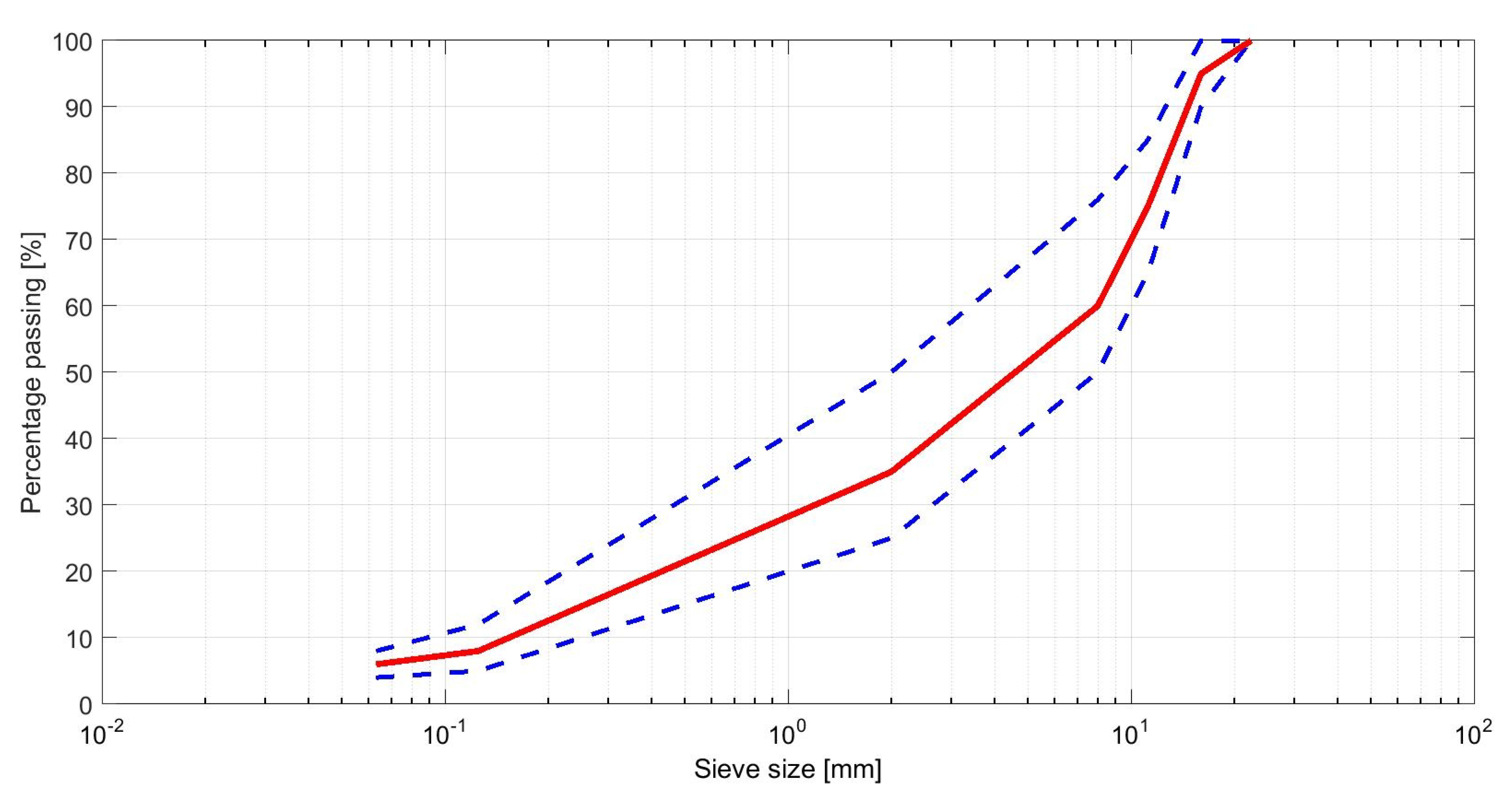
In numerical analyses, the AC grading curves should be incorporated into the synthetic microstructure modeling algorithms to reflect its real morphology. Due to the resources limitations, one accounts only for the part of the prescribed curve, e.g., in [16], the value of 2 mm was used as a threshold. In Figure 1, one can observe an exemplary grading curve (red solid line) that can be used for the modeling purposes. Setting the threshold value for the minimum grain size to be considered in the analysis is specific to the type of AC used and the computational resources. For instance, using the value of 2 mm in the case of the mixture presented in Figure 1 would exclude nearly a half of the grains from the analysis.
In our paper, we present a methodology of AC microstructure generation accounting for the prescribed grading curve. We combine and modify certain known concepts in order to speed up the process.
Another issue addressed in this paper is the multiscale analysis of AC. The multiscale finite element method is used for this purpose. It enables for a large reduction of the degrees of freedom (and the CPU time) used in direct numerical analysis with the overkill mesh. Both of the components used together can be very beneficial in the case of the tests performed on novel asphalt mixtures. They can reduce the costs of the whole design process substituting some of the laboratory experiments, giving the opportunity to test the developed constitutive models and speeding up the numerical analysis itself.
2. Materials and Methods
A reliable modeling of the AC microstructure plays a vital role in the whole numerical analysis. As reported in [4], not only the spatial distribution of the aggregate particles and their gradation influence the behavior of the asphalt materials subjected to the external loads, but also the morphology of these inclusions has to be carefully modeled, as it has a strong impact on the overall response due to different mechanisms of the particles clinching and interaction that depend on the inclusion shapes. Thus, we present below our algorithm for an effective modeling of the AC microstructure.
At the considered scale of AC analysis, its microstructure does not change in time. Thus, the time used for this generation influences the whole numerical analysis only once. What is really crucial, is the time used for the main physical analysis. For the sake of the CPU time reduction, we propose the multiscale finite element method, which is one of the possible upscaling techniques. Its main advantages are: no periodicity and no separation of scales requirements. From the numerical perspective, an easy parallelization is also profitable. For the purposes of this paper, we assumed only the linear elastic material model but any other is also applicable. In [15], we presented the methodology and numerical results for the viscoelasticity problem for a simple geometry of inclusions.
2.1. Microstructure Generation
The algorithms for the AC microstructure generation can be roughly divided into two main groups. The distinction is based on the modeled domain. If the task is to generate the microstructure for a given real sample, then the X-ray computed tomography (XRCT) is typically used. This approach is very versatile and reliable, as it enables consideration of a real sample in the numerical model. A number of the XRCT scans is generated. Then, they are sharpened and binarized to reflect the material spatial distribution. Finally, the microstructure is generated on a set of such scans. In the context of the further numerical analysis, this approach is very often prohibitively expensive. For the AC modeling purposes, the resolution of the scans was reported in [7] as the main limitation. It is due to the fact, that 1 voxel is assosiated in the finite element method (FEM) with a single element. It leads to the overkill meshes that are unecessary in such a relatively simple geometry as the shapes of particles. In [7], it was presented that voxels were used to model a cube of the edge length equal to 24.5 mm. In order to make the analysis of such a domain feasible, a geometry simplification is performed (c.f. [4]).
The alternative approach is to generate a fully synthetic microstructure without any mapping of the real domain. In the case of AC, this approach is justified, as its microstructure is random. There are two main parameters that are to be preserved in the numerical modeling of this material: total volumetric ratios of the matrix and the inclusions as well as the particle size distribution determined by the gradation curve. As reported in [4], the angularity of the aggregate particles plays also a vital role in the behavior of the structures (cylindrical samples, therein) made of AC. There is a large body of the literature devoted to the AC microstructure generation (see, e.g., in [3,4,5,7,13,14,16,17]). The analized geometry was substantially simplified (c.f. [17]), where the research was focused on the ravelling process. The approach based on th XRCT scans was used for the real samples analyzed in a laboratory experiment to compare the results with the numerical analysis [4] or in the numerical simulations reproducing the laboratory tests [13]. However, the synthetic microstructure generation is frequently used to overcome the resources limitations [7,16]. This approach is also used in the cases, where the focus is on the feasibility of the nonlinear analysis or new constitutive model introduction [3,5,13,14].
The algorithm we propose in this paper is a combination of the approaches presented in the aforementioned papers with some modifications. We have implemented it in 2D but it is not limited to this case.
2.1.1. Generation of Spheres (Circles)
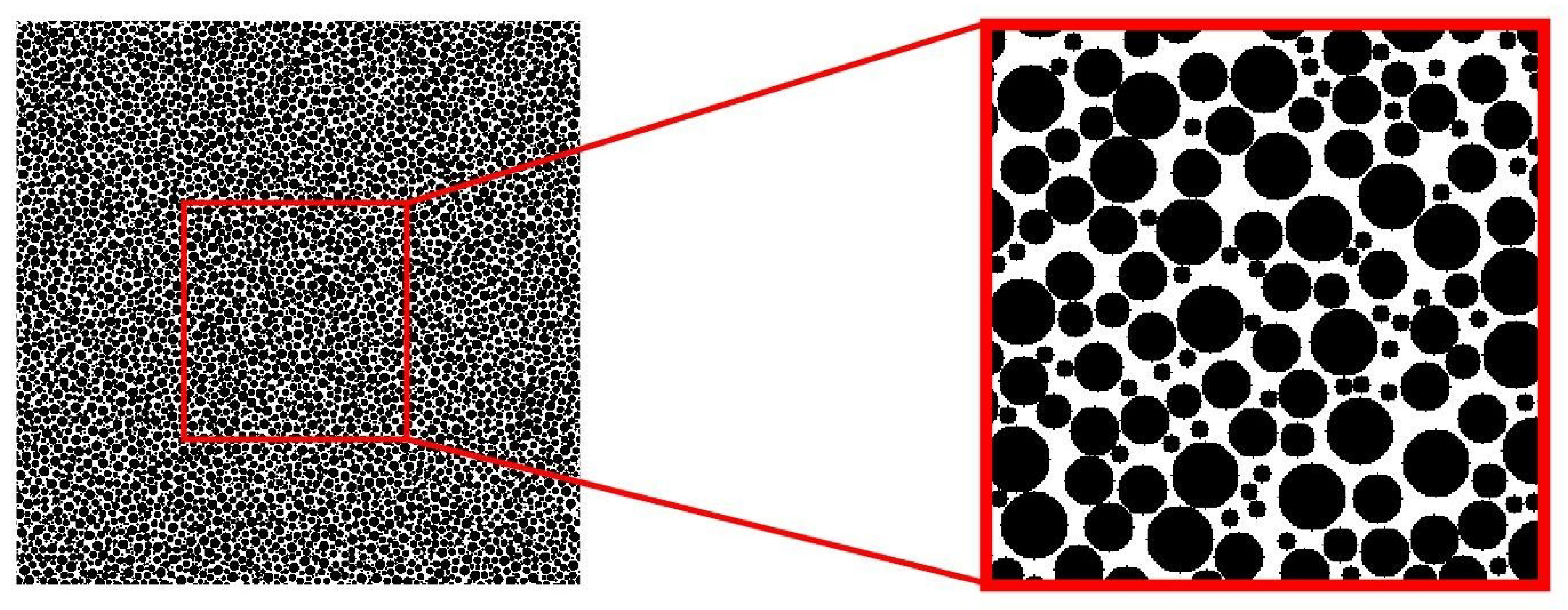
The input to our algorithm is the geometry of the analyzed domain, the total volumetric ratio of the constituents and the particle size distribution. Using the Synthetic Microstructure Generator [18], we begin with the distribution of spheres in the oversampled domain as presented in Figure 2. This occurs because the algorithm used in the code does not guarantee 100% particles generation. At this level, the particle size distribution is crucial. The total volume of the phases is controlled in the next steps. As it can be seen in Figure 2, not all of the spheres are in contact. This drawback was efficiently removed in [14] by the molecular dynamics algorithm with the boundary being squeezed. However, we will justify our simplified approach in the next step description.
2.1.2. Voronoi Tessellation
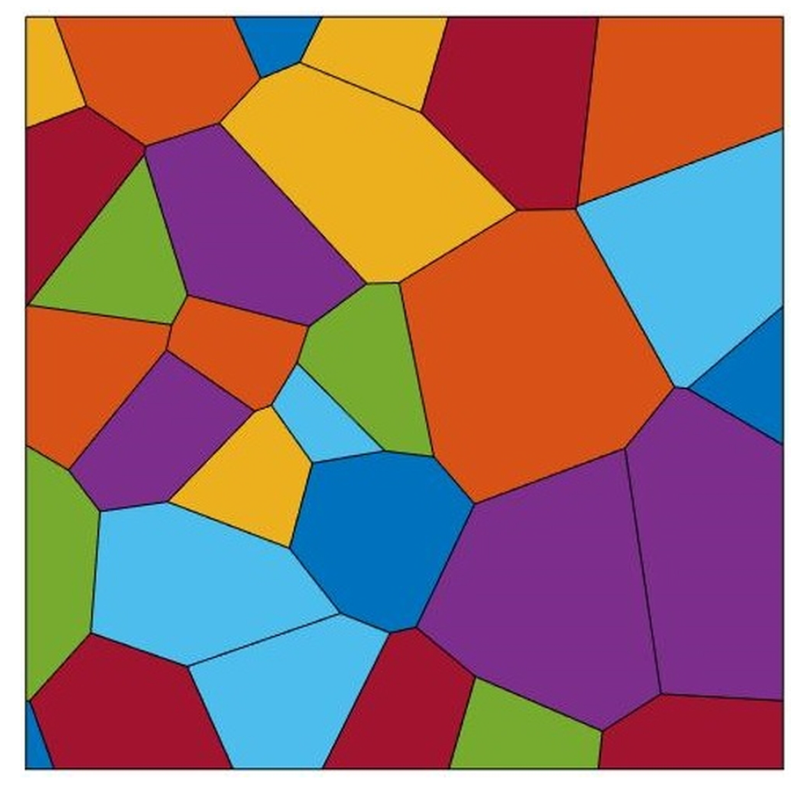
In this step, we associate each of the circles center with the seed of the Voronoi tessellation. As demonstrated in [7], the differences between the input particle size distribution and its counterpart obtained by the Voronoi tesselation are acceptable. Similarly, the differences between the molecular dynamic approach mentioned in the previous chapter and the one advocated in this study do not introduce meaningful discrepancies to the prescribed grading curve. An exemplary Voronoi tessellation within the analyzed domain for a given seed set is presented in Figure 3.
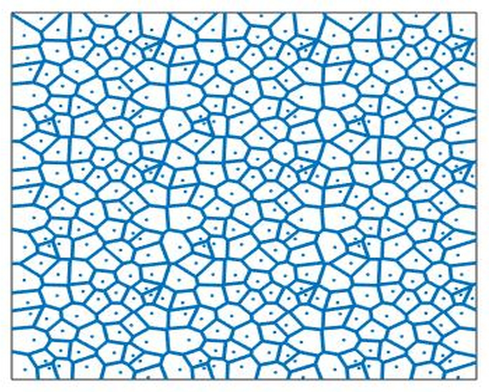
To remove the boundary effect (non uniqueness of the outermost polygon shapes) and provide the periodicity of the generated tessellation, we perform a number of auxiliary amendments. The given set of seeds is copied eight times (see Figure 4) to have a 3 × 3 oversampling domain. The periodicity of Voronoi seeds guarantees the periodicity of the tesselation within the subdomain in the middle, when it is cut out for the further editing.
2.1.3. Shrinkage Procedure
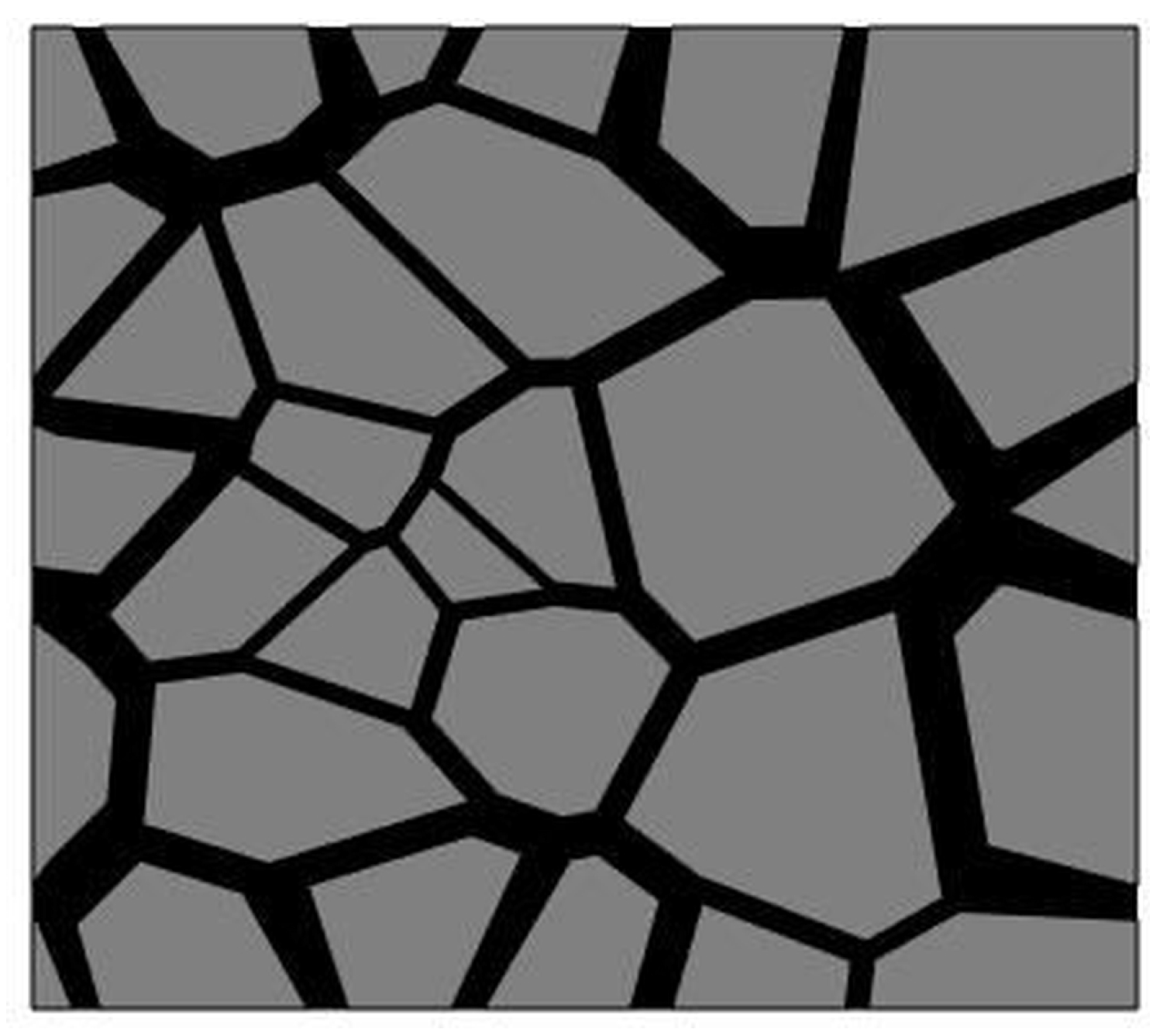
To preserve the prescribed total volume ratio of the constituents, the shrinkage procedure (c.f. [14,16]) is performed on the Voronoi cells. For these in the interior, the scaling operation with the given scale factor is done. The base point for this operation is the gravity center of each individual cell. The outermost entities adjacent to the boundary require slightly modified approach if the shape of the analyzed domain is to be preserved. Namely, we scale these cells initially but for the two vertices (in 2D) on the boundary we modify only one respective coordinate. An exemplary result of the shrinkage procedure is shown in Figure 5.
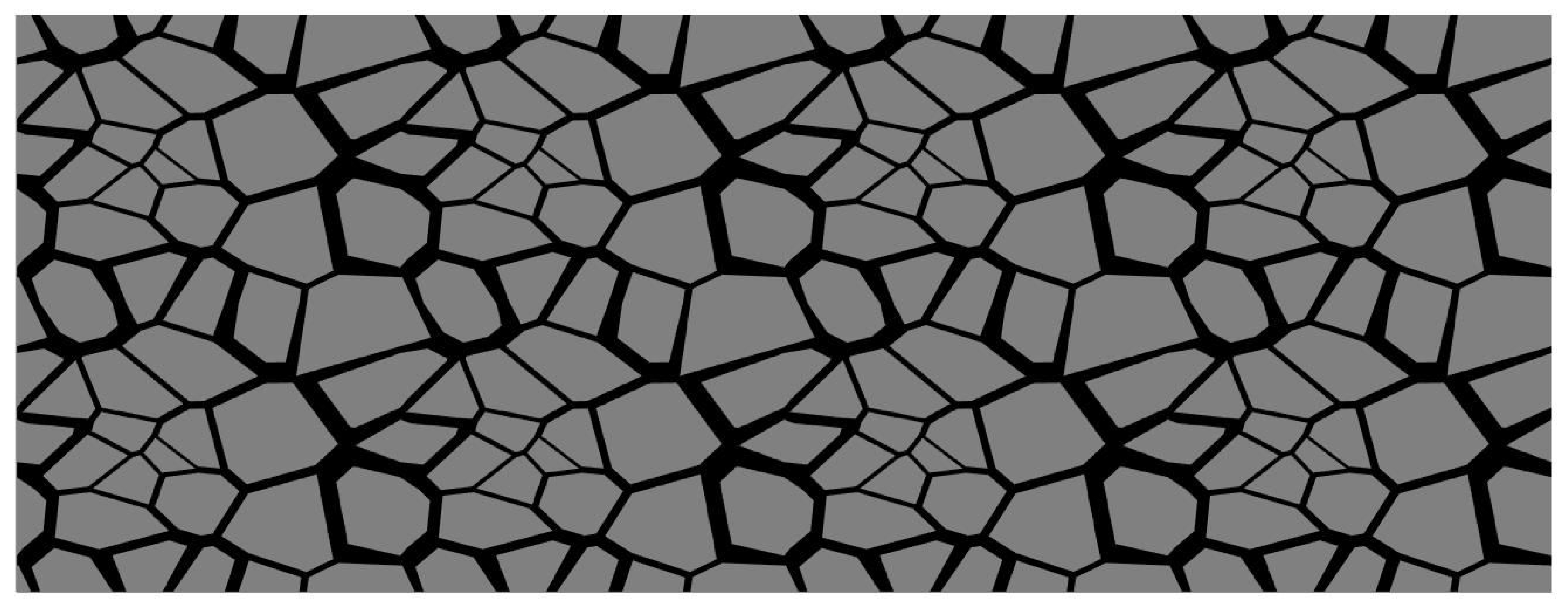
Therefore, a generated sample domain with randomly distributed inclusions is multiplicated in order to obtain the whole domain necessary for the analysis. In general, the multiplication is not required but speeds up the computation. As shown in Figure 6, a 2 × 4 synthetic microstructure generated using this methodology is locally non-periodic.
2.2. Multiscale Modeling
In the 2D linear elastic computations with relatively small analyzed domain (which is the case of the numerical test presented in this paper), no multiscale approach is necessary. However, addressing the proposed framework to the 3D nonlinear analysis of the whole pavement structure, it is unavoidable.
In our research [15,19], we develop the multiscale finite element method (MsFEM) that is a versatile tool, e.g., for the AC modeling. In the aforementioned papers, the method (its extension to the higher order approximation) is introduced and thoroughly described. In this paper, we restrict ourselves to a brief description of its workflow. We proceed with two meshes: a coarse mesh used for the main problem solution and a set of fine meshes within coarse elements. The fine meshes comply with the microstructure but the solution obtained on a global fine mesh (with gluing all fine meshes) is typically very expensive or infeasible. Thus, we take advantage of the microresolution information to compute the effective coarse element stiffness matrices and load vectors. Finally, we solve the main problem using the coarse mesh with the effective quantities and reasonable number of DOFs (degrees of freedom) reduction.
The idea of the MsFEM is based on the concept of the special shape functions (c.f. [20,21]). Starting with the standard coarse element shape functions, we modify them to account for the oscillations of the material parameters. The price of the MsFEM is the solution of the N local boundary value problems (BVP) recapitulated below, where N is the number of the coarse element shape functions. The strong form of the BVP to be solved within the subdomain (a coarse element) is recalled.
Given , which is a coarse mesh vector-valued shape function, we look for its vector-valued counterpart that is a discrete solution of the following Dirichlet boundary value problem with
The exemplary function and essential boundary conditions () can be found, e.g., in [15,19]. Also, we refer the reader to the aforementioned papers for a thorough description on how the Dirichlet boundary conditions are defined on . In [15], we presented also a number of examples of the modified shape functions and further numerical tests. Solution to N Problems (1) constitutes the prolongation operator and allows one for the computation of the effective coarse element stiffness matrix and load vector, respectively,
in terms of and , which denote the fine mesh stiffness matrix and load vector assembled within the domain occupied by the analyzed coarse mesh element in such a setting.
The generation of the (only) locally non periodic microstructure, we advocated on in the previous chapter, is justified by the computation speed-up; thus, the effective coarse mesh element quantities have to be computed only once and used for each of these elements.
3. Results
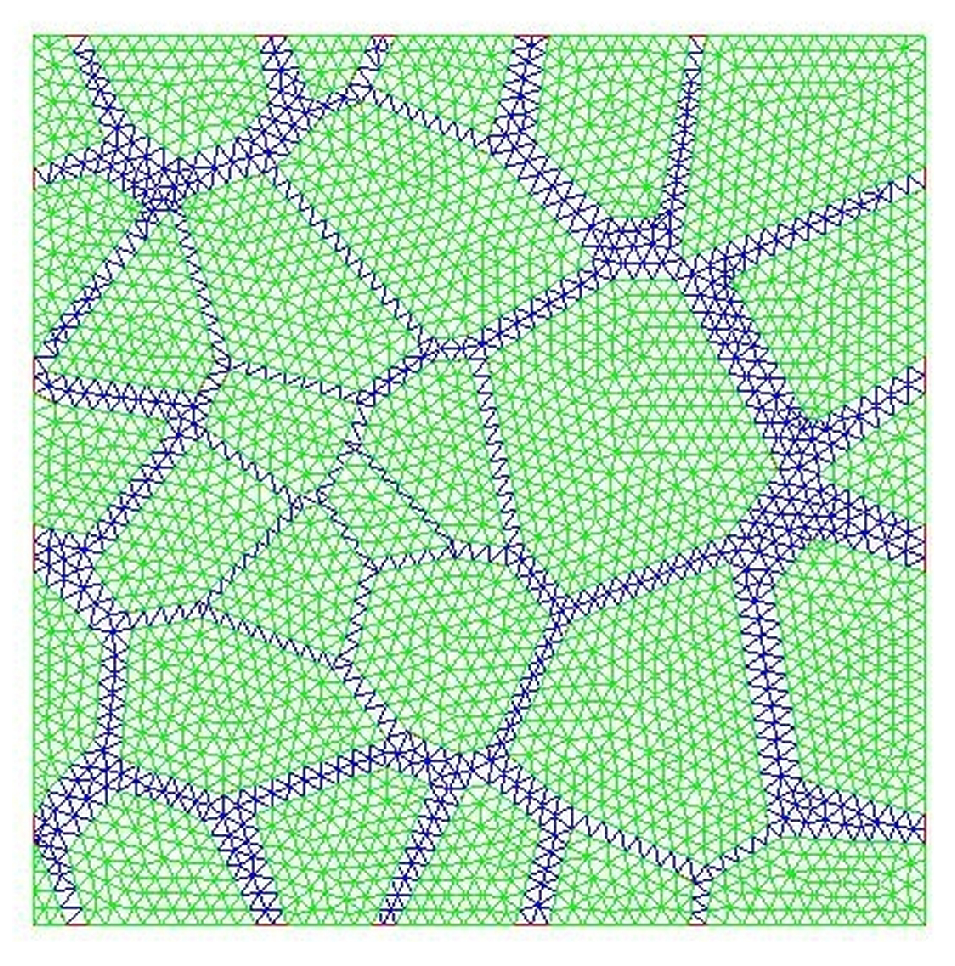
To demonstrate the effectiveness of the MsFEM for AC, we present below a simple test. Therein, we analyze the heterogeneous domain with the microstructure generated as presented in Section 2.1. A single coarse element is a square of dimensions 15 cm × 15 cm with the microstructure shown in Figure 5. The fine mesh complying with the inclusion spatial distribution is shown in Figure 7. Material data for the elastic analysis are as follows,
- for the aggregate particles (inclusions) − GPa, , and
- for the mastic (matrix) − GPa, .
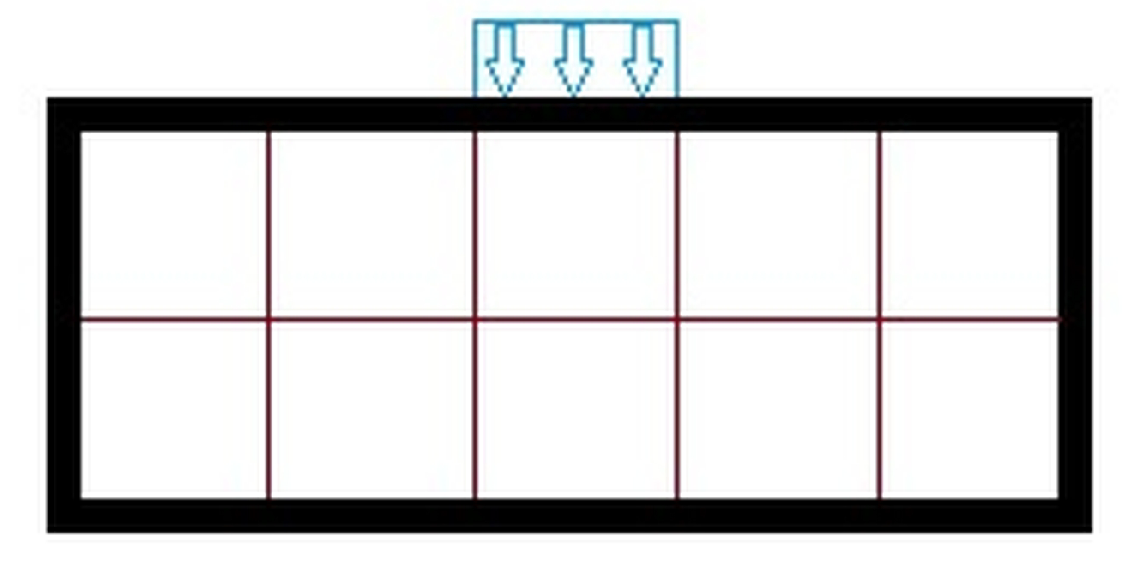
We analyze one idealized layer of dimensions 30 cm × 75 cm made of AC (see Figure 8 ) in the plane strain state. The bottom edge is fixed and a part of the top one is loaded ( kN/m). At the macroresolution, the domain is meshed with 2 × 5 coarse elements. For each of them, we use the fine mesh presented in Figure 7 because of the speed-up in computations—the effective stiffness matrix and load vector can be computed once and reused for all coarse elements.
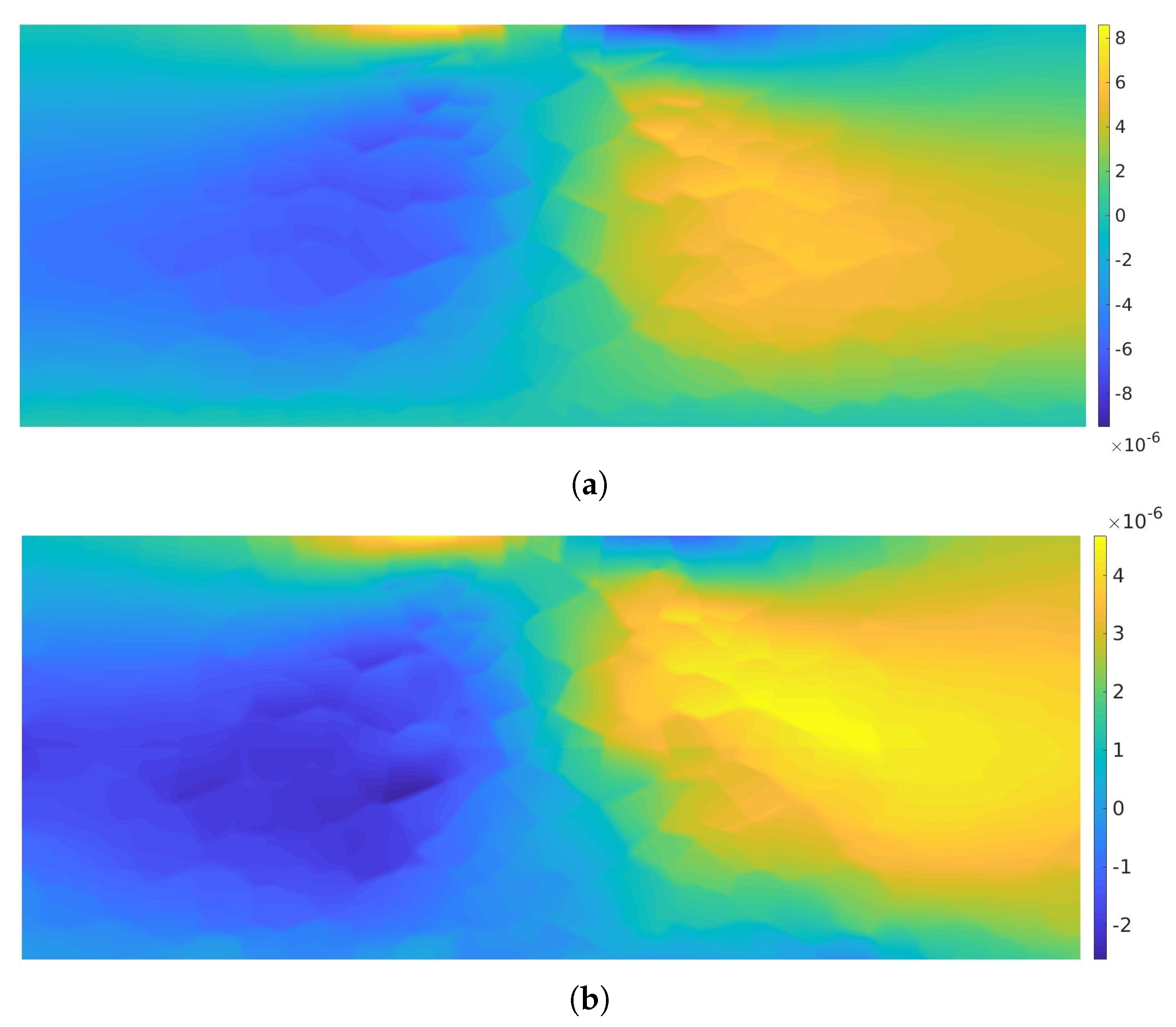
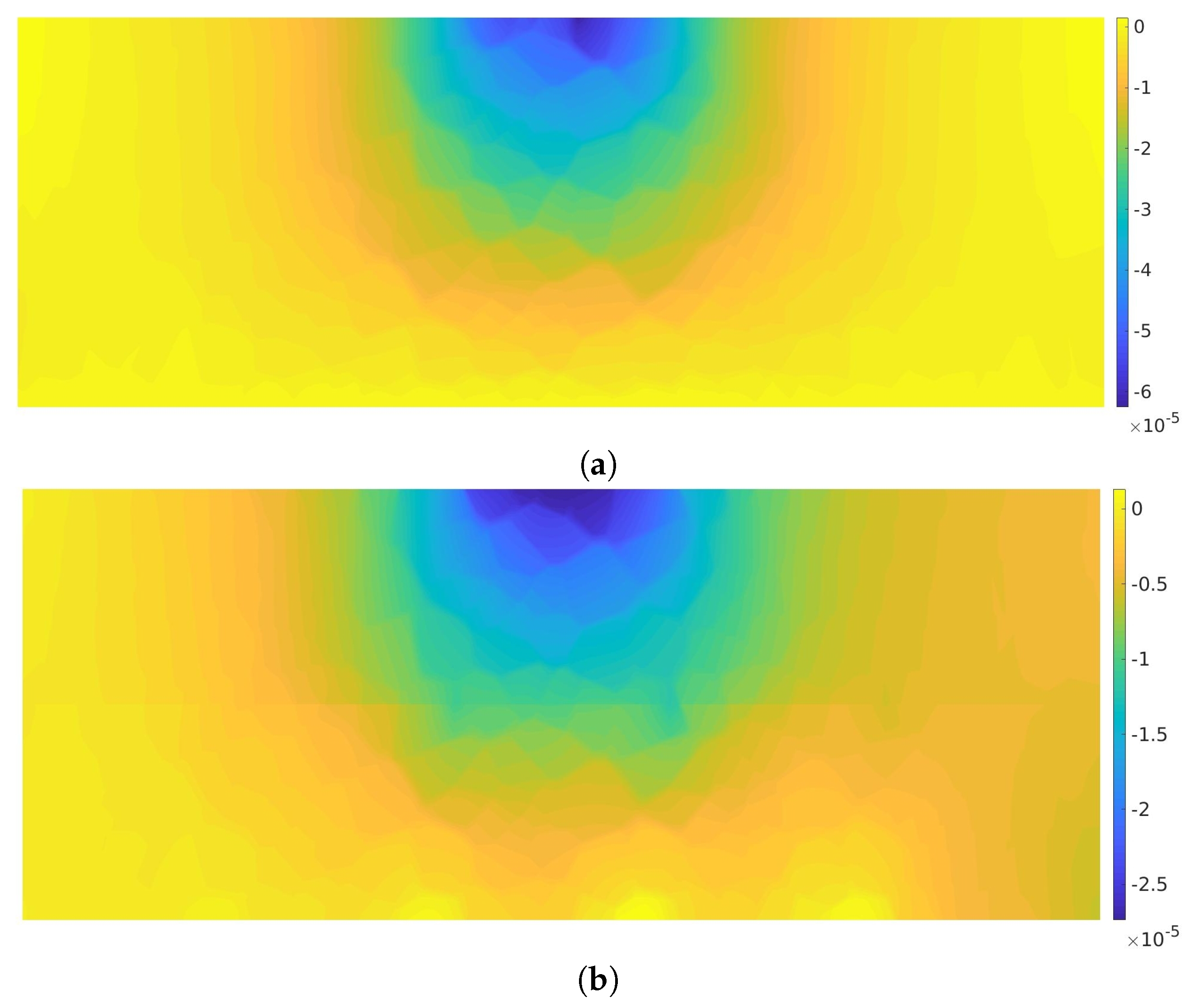
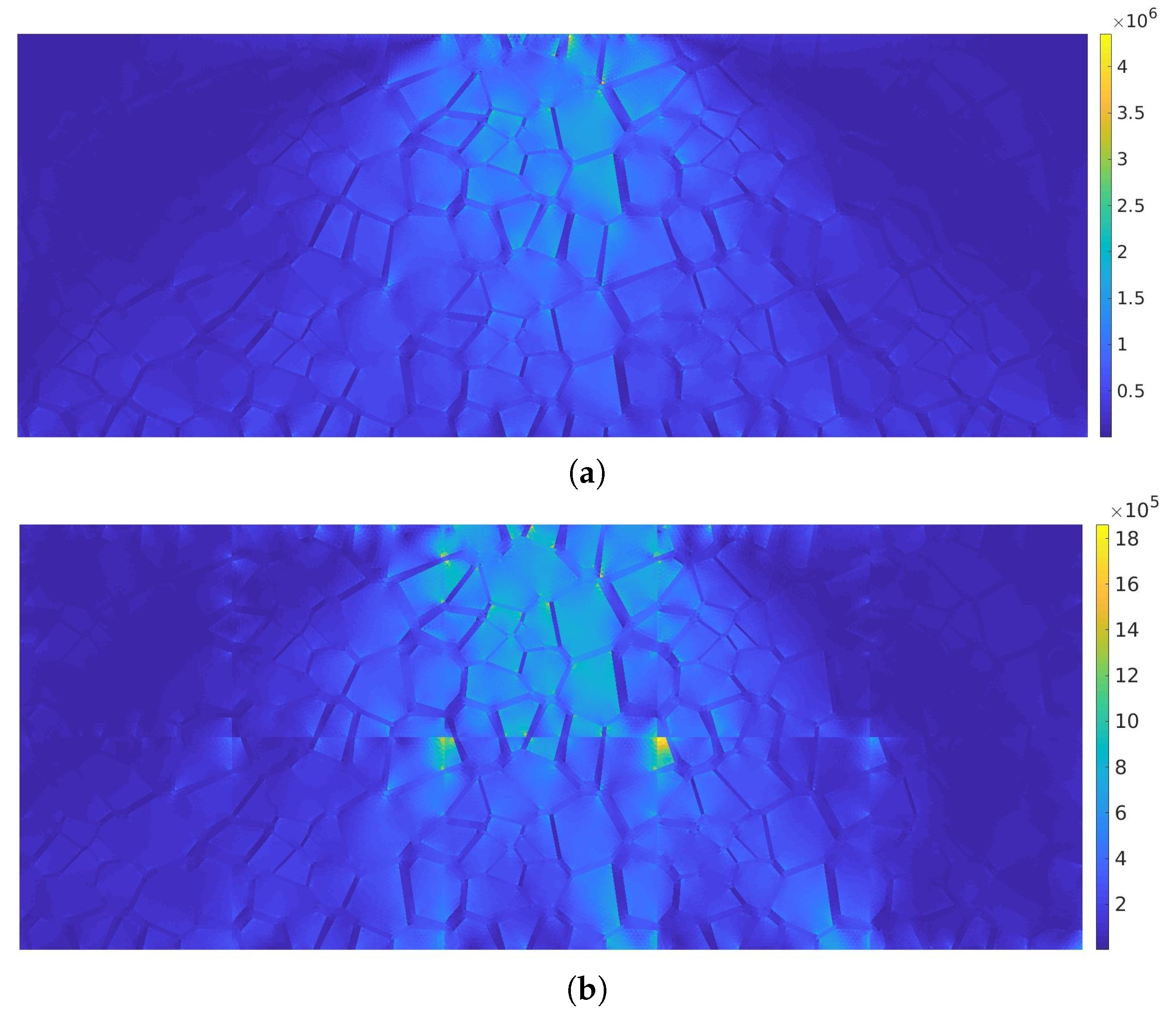
The displacement components are shown in Figure 9 and Figure 10 and the Mises stress is shown in Figure 11. The top rows presents therein the reference solutions obtained using the fine mesh (about 60,000 degrees of freedom). The upscaled solutions obtained using only 10 coarse elements with the high approximation order (p = 5) and approximately 600 degrees of freedom is presented in the bottom row.
Considering the reduction of the DOF number (~100 times) and the CPU time (~10 times), the results presented in this Section are qualitatively acceptable. The improvement of the upscaled solution accuracy can be obtained decreasing the size of the coarse scale elements or increasing the approximation order at that scale (c.f. [15,19]). This can be also done at the microresolution level. The study on the MsFEM accuracy and convergence was presented in [15,19]. In [15], we used the hp-adaptivity at the macroresolution level. Practically, the trade off between the accuracy and computation time is up to the user. In order to verify the upscaled solution accuracy, one can use existing error estimates that can qualitatively measure the introduced error.
4. Conclusions
In this paper, we proposed an improved algorithm for the AC microstructure generation. Subsequently, the idea of the MsFEM was recalled. This upscaling method was used to solve a plane strain problem within a domain generated using the aforementioned algorithm. The MsFEM turned out to produce reliable results with a large reduction of NDOF and CPU time.
The whole methodology presented in this paper is addressed to the design of novel asphalt mixtures. The numerical modeling itself can reduce the number of necessary laboratory experiments. The multiscale analysis offers further speed-up (with the controlled introduced error) to the design process. Thus, the advocated methodology can be very frugal in the context of time, which is very advantageous considering the whole design process. It enabled 10 times faster computation with ~50% of modeling error.
Our future research effort is the further development of the algorithm for AC microstructure generation and the comparison of numerical tests with laboratory experiments. Implementation of nonlinear material models [15,22,23] and mixed problems is necessary, thus. In such a setting, our framework can be accommodated for the tests of the novel asphalt materials producing reliable results in a shorter time than using direct overkill mesh analysis.
Author Contributions
Conceptualization, M.K. and W.C.; methodology, M.K.; investigation, M.K. and W.C.; writing—original draft preparation, M.K.; writing—review and editing, M.K. and W.C. All authors have read and agreed to the published version of the manuscript.
Funding
This research was funded by Narodowe Centrum Nauki (Poland) grant number UMO-2017/25/B/ST8/02752. The APC was funded by the Dean of the Civil Engineering Faculty (Cracow University of Technology).
Conflicts of Interest
The authors declare no conflicts of interest. The funders had no role in the design of the study; in the collection, analyses, or interpretation of data; in the writing of the manuscript; or in the decision to publish the results.
References
- Porto, M.; Caputo, P.; Loise, V.; Eskandarsefat, S.; Teltayev, B.; Rossi, C.O. Bitumen and Bitumen Modification: A Review on Latest Advances. Appl. Sci. 2019, 9, 742. [Google Scholar] [CrossRef] [Green Version]
- Collop, A.; Scarpas, A.; Kasbergen, C.; de Bondt, A. Development and finite element implementation of a stress dependent elasto-visco-plastic constitutive model with damage for asphalt. Transp. Res. Rec. 2003, 1832, 96–104. [Google Scholar] [CrossRef]
- Kim, Y.; Souza, F.; Teixeira, J. A two-way coupled multiscale model for predicting damage-associated performance of asphaltic roadways. Comput. Mech. 2013, 51, 187–201. [Google Scholar] [CrossRef]
- Liu, P.; Hu, J.; Wang, D.; Oeser, M.; Alber, S.; Ressel, W.; Fala, G. Modelling and evaluation of aggregate morphology on asphalt compression behavior. Constr. Build. Mater. 2017, 133, 196–208. [Google Scholar] [CrossRef]
- Mitra, K.; Das, A.; Basu, S. Mechanical behavior of asphalt mix: An experimental and numerical study. Constr. Build. Mater. 2012, 27, 545–552. [Google Scholar] [CrossRef]
- Schüller, T.; Manke, R.; Jänicke, R.; Radenberg, M.; Steeb, H. Multi-scale modelling of elastic/viscoelastic compounds. ZAMM J. Appl. Math. Mech. 2013, 93, 126–137. [Google Scholar] [CrossRef]
- Schüller, T.; Jänicke, R.; Steeb, H. Nonlinear modeling and computational homogenization of asphalt concrete on the basis of XRCT scans. Constr. Build. Mater. 2016, 109, 96–108. [Google Scholar] [CrossRef]
- Woldekidan, M.; Huurman, M.; Pronk, A. Linear and Nonlinear Viscoelastic Analysis of Bituminous Mortar. Transp. Res. Rec. J. Transp. Res. Board 2013, 2370, 53–62. [Google Scholar] [CrossRef]
- Dai, Q.; You, Z. Prediction of creep stiffness of asphalt mixture with micromechanical finite-element and discrete-element models. J. Eng. Mech. 2007, 133, 163–173. [Google Scholar] [CrossRef] [Green Version]
- Arshadi, A.; Bahia, H. Development of an image-based multi-scale finite-element approach to predict mechanical response of asphalt mixtures. Road Mater. Pavement Des. 2015, 16, 214–229. [Google Scholar] [CrossRef]
- Aigner, E.; Lackner, R.; Pichler, C. Multiscale Prediction of Viscoelastic Properties of Asphalt Concrete. J. Mater. Civ. Eng. 2009, 21, 771–780. [Google Scholar] [CrossRef] [Green Version]
- Al-Rub, R.; You, T.; Masad, E.; Little, D. Mesomechanical modeling of the thermo-viscoelastic, thermo-viscoplastic, and thermo-viscodamage response of asphalt concrete. Int. J. Adv. Eng. Sci. Appl. Math. 2011, 3, 14–33. [Google Scholar] [CrossRef]
- You, T.; Al-Rub, R.; Darabi, M.; Masad, E.; Little, D. Three-dimensional microstructural modeling of asphalt concrete using a unified viscoelastic-viscoplastic-viscodamage model. Constr. Build. Mater. 2012, 28, 531–548. [Google Scholar] [CrossRef]
- Ziaei-Rad, V.; Nouri, N.; Ziaei-Rad, S.; Abtahi, M. A numerical study on mechanical performance of asphalt mixture using a meso-scale finite element model. Finite Elem. Anal. Des. 2012, 57, 81–91. [Google Scholar] [CrossRef]
- Klimczak, M.; Cecot, W. An adaptive MsFEM for non periodic viscoelastic composites. Int. J. Numer. Methods Eng. 2018, 114, 861–881. [Google Scholar] [CrossRef]
- Wimmer, J.; Stier, B.; Simon, J.W.; Reese, S. Computational homogenisation from a 3D finite element model of asphalt concrete–linear elastic computations. Finite Elem. Anal. Des. 2016, 110, 43–57. [Google Scholar] [CrossRef]
- Mo, L.; Huurman, M.; Wu, S.; Molenaar, A. 2D and 3D meso-scale finite element models for ravelling analysis of porous asphalt concrete. Finite Elem. Anal. Des. 2008, 44, 186–196. [Google Scholar] [CrossRef]
- Tschopp, M.; Wilks, G.; Spowart, J. Multi-scale characterization of orthotropic microstructures. Model. Simul. Mater. Sci. Eng. 2008, 16, 065009. [Google Scholar] [CrossRef]
- Cecot, W.; Oleksy, M. High order FEM for multigrid homogenization. Comput. Math. Appl. 2015, 70, 1391–1400. [Google Scholar] [CrossRef]
- Efendiev, Y.; Hou, T. Multiscale finite element methods for porous media flows and their applications. Appl. Numer. Math. 2007, 57, 577–596. [Google Scholar] [CrossRef] [Green Version]
- Hou, T.; Wu, X. A multiscale finite element method for elliptic problems in composite materials and porous media. J. Comput. Phys. 1997, 134, 169–189. [Google Scholar] [CrossRef] [Green Version]
- Cecot, W. Adaptive FEM analysis of selected elastic-visco-plastic problems. Comput. Methods Appl. Mech. Eng. 2007, 196, 3859–3870. [Google Scholar] [CrossRef]
- Cecot, W. Application of h-adaptive FEM and Zarka’s approach to analysis of shakedown problems. Int. J. Numer. Methods Eng. 2004, 61, 2139–2158. [Google Scholar] [CrossRef]
Figure 1.
An exemplary grading curve of asphalt concrete AC16P used for the subbase in Poland for the traffic categories KR3 ÷ 7. The blue dashed lines denote the bounding curves and the red solid line denotes the grading curve of the analyzed mixture.
Figure 1.
An exemplary grading curve of asphalt concrete AC16P used for the subbase in Poland for the traffic categories KR3 ÷ 7. The blue dashed lines denote the bounding curves and the red solid line denotes the grading curve of the analyzed mixture.

Figure 2.
The oversampled (left) and the analyzed domain (right).

Figure 3.
An exemplary Voronoi tessellation.

Figure 4.
The oversampled domain with the corresponding Voronoi tessellation.

Figure 5.
An exemplary Voronoi tessellation after the shrinkage procedure.

Figure 6.
An exemplary Voronoi tessellation after the shrinkage procedure and multiplication in a 2 × 4 pattern.
Figure 6.
An exemplary Voronoi tessellation after the shrinkage procedure and multiplication in a 2 × 4 pattern.

Figure 7.
The fine mesh within a single coarse element.

Figure 8.
The analyzed domain of dimensions 30 cm × 75 cm discretized with 10 coarse finite elements.
Figure 8.
The analyzed domain of dimensions 30 cm × 75 cm discretized with 10 coarse finite elements.

Figure 9.
displacement component: (a) reference solution obtained with ≈60,000 DOFs and (b) upscaled solution obtained with ≈600 DOFs [m].
Figure 9.
displacement component: (a) reference solution obtained with ≈60,000 DOFs and (b) upscaled solution obtained with ≈600 DOFs [m].

Figure 10.
displacement component: (a) reference solution obtained with ≈60,000 DOFs and (b) upscaled solution obtained with ≈600 DOFs [m].
Figure 10.
displacement component: (a) reference solution obtained with ≈60,000 DOFs and (b) upscaled solution obtained with ≈600 DOFs [m].

Figure 11.
Mises stress: (a) reference solution obtained with ≈ 60,000DOFs and (b) upscaled solution obtained with ≈600 DOFs [Pa].
Figure 11.
Mises stress: (a) reference solution obtained with ≈ 60,000DOFs and (b) upscaled solution obtained with ≈600 DOFs [Pa].

© 2020 by the authors. Licensee MDPI, Basel, Switzerland. This article is an open access article distributed under the terms and conditions of the Creative Commons Attribution (CC BY) license (http://creativecommons.org/licenses/by/4.0/).
Share and Cite
MDPI and ACS Style
Klimczak, M.; Cecot, W. Synthetic Microstructure Generation and Multiscale Analysis of Asphalt Concrete. Appl. Sci. 2020, 10, 765. https://doi.org/10.3390/app10030765
AMA Style
Klimczak M, Cecot W. Synthetic Microstructure Generation and Multiscale Analysis of Asphalt Concrete. Applied Sciences. 2020; 10(3):765. https://doi.org/10.3390/app10030765
Chicago/Turabian StyleKlimczak, Marek, and Witold Cecot. 2020. "Synthetic Microstructure Generation and Multiscale Analysis of Asphalt Concrete" Applied Sciences 10, no. 3: 765. https://doi.org/10.3390/app10030765
Note that from the first issue of 2016, this journal uses article numbers instead of page numbers. See further details here.