Shock Loading of Closed Cell Aluminum Foams in the Presence of an Air Cavity


1
Indian Institute of Technology Bombay, Powai, Mumbai 400076, India
2
Defence Metallurgical Research Laboratory, Hyderabad 500058, India
3
International Research Organization for Advanced Science and Technology (IROAST; Visiting Professor), Kumamoto University, Kumamoto 860-8555, Japan
4
Institute of Industrial Nanomaterials, Kumamoto University, Kumamoto 860-8555, Japan
*
Author to whom correspondence should be addressed.
Appl. Sci. 2020, 10(12), 4128; https://doi.org/10.3390/app10124128
Submission received: 8 April 2020
/
Revised: 9 June 2020
/
Accepted: 12 June 2020
/
Published: 16 June 2020
Abstract
:Featured Application
The article establishes the potential of ultra-light, closed cell aluminum foam to attenuate shocks when interfaced with air-cavities. The specific aim of the work is to capture the pressure signatures inside small cavities in steel end-walls of a shock tube when exposed to shocks, without and with foam shields of various densities.
Abstract
It is important to protect assets located within cavities vulnerable to incident shock waves generated by explosions. The aim of the present work is to explore if closed cell aluminum foams can mediate and attenuate incident shocks experienced by cavities. A small cavity of 9 mm diameter and 2 mm length was created within the steel end-wall of a shock tube and exposed to shocks, directly or after isolating by aluminum foam liners. Shock waves with incident pressure of 9–10 bar travelling at a velocity of 1000–1050 m/s were generated in the shock tube. Compared to the no-foam condition, the pressure induced in the cavity was either equal or lower, depending on whether the foam density was low (0.28 g/cc) or high (0.31 to 0.49 g/cc), respectively. Moreover, the rate of pressure rise, which was very high without and with the low density foam barrier, reduced substantially with increasing foam density. Foams deformed plastically under shock loading, with the extent of deformation decreasing with increasing foam density. Some interesting responses such as perforation of cell walls in the front side and densification in the far side of the foam were observed by a combination of scanning electron microscopy and X-ray microscopy. The present work conclusively shows that shocks in cavities within rigid walls can be attenuated by using foam liners of sufficiently high densities, which resist densification and extrusion into the cavities. Even such relatively high-density foams would be much lighter than fully dense materials capable of protecting cavities from shocks.
1. Introduction
Closed cell aluminum foams are known to absorb a significant amount of energy during quasi-static compression by undergoing a large amount of plastic deformation at low transmitted stress [1]. Plastic deformation occurs in bands of cells by cell wall bending and buckling, causing cell collapse and foam densification [2]. Mazor et al. [3] and Ben-Dor et al. [4] carried out mathematical analyses and limited experiments of head-on collisions of planar shock waves of Mach 1.08–1.41 in a rectangular shock tube with ultra-low density, (0.03 g/cc) polyurethane foams placed against the end-wall of a shock tube. They found that the reflected pressure from the front face of the foam was less than that from the end-wall of the empty shock tube, which was termed as “shock attenuation”. However, the pressure generated by the wave after transmission through the foam, reflection from the end-wall, transmission back through the foam, and re-emergence from the front face was found to be more than the reflected pressure off the end-wall of the empty shock tube, which was termed as “shock amplification”. According to the authors, shock amplification occurs while the foam deformation is restricted to the plateau domain, i.e., the region in the compressive stress–strain relationship of foams in which large strains occur at low and near-constant stress, since under such conditions compression waves inside the foam can transform into shock waves.
Rempel and Schmidt [5] studied the compaction behavior of high density (0.7 to 1.4 g/cc) porous aluminum and found the permissible momentum and minimum areal density of porous aluminum required to prevent the plastic waves from reaching the anvil. Linde and Schmidt [6] studied the behavior of high relative density (0.4–0.8, i.e., in the absolute density range 1.1–2.2 g/cc) porous aluminum under shock loading and calculated the Hugoniot conditions, which are shown to be dependent on strength and coherence of the solid matrix. The porous aluminum was shown to condense to its full density after exposure to about 10 kbar of shock pressure, generated using impact of projectiles on targets.
Petel et al. [7] studied the elastic-plastic behavior of polyurethane foams on blast wave and shock tube loading. They observed that a compaction wave induced in the foam due to shock loading exerted a greater stress on the end-wall of the shock tube, than the incident shock wave in the absence of the foam (the baseline case). In other words, a shock-exposed polyurethane foam amplified the stress on the posterior object. They noted that if several interfaces with increasing impedances exist in the path of a compression wave, the stress generated at each interface gets added, and results in stress amplification. Thus, in an air-foam-steel system, where the foam has an impedance value intermediate to those of air and steel, a higher amount of stress is expected on the steel when a shock wave generated in air impacts the foam.
Gas filtration through granular layers during weak shock wave impact was studied by Britan et al. [8]. Sensors placed in front of the granular medium showed an initial steep rise in pressure, the amplitude of which was inversely proportional to the permeability of the medium, followed by gradual rise reaching up to a steady value, which is attributed to gas filtration and reflection of the compaction wave from the rigid wall at the end of the shock tube. The pressure at the rigid wall, measured by an unprotected sensor inserted into the granular medium, shows an unsteady steep rise in pressure, attributed to the effect of compaction wave on the gas pressure, followed by a drop and attainment of a steady value due to gas filtration.
Effect of length of a granular material medium on attenuation of blasts was studied by Britan et al. [9]. They showed that the relative exit overpressure decreased with increase in length of the granular medium and decrease in Mach number of the shock wave. They further showed that the presence of an air gap (of the order of 106 mm) between the granular filter and the protected surface prevents direct contact between the particles composing the granular medium and the protected surface, which eliminates unsteady peak pressures/stresses on the protected surface that are seen in the absence of the air gap.
Hosseini et al. [10] studied the shock wave interaction with materials having different acoustic impedances. They found that an underwater shock wave, which was expected to reflect totally as an unloading wave at the water–air interface due to acoustic impedance mismatch, was observed transmitting across the interface to air.
Schenker et al. [11] carried out full-scale field explosion tests on concrete slabs, with and without aluminum foam cover. They studied the dynamic response of an elementary concrete structure to blast wave loads, and the ability of aluminum foams to mitigate the blast loads. They reported that the aluminum foam could modify the response of the slab to the blast load but stated that further investigation would be required to predict its efficiency for practical purposes.
Goel et al. [12] showed that the reflected shock pressure measured in front of simply supported aluminum foams placed at the end of a shock tube cavity was higher (2.9× the incident pressure) than that produced by a rigid aluminum plate (2× the incident pressure). The shock speed used was greater than Mach 2 while the incident pressure was 3.5 bar, which gives reflected pressures of about 10 bar. Reddy et al. [13] showed that, for higher values of reflected pressure (52 and 69 bar), radial cracks and core crushing occurred in simply supported closed cell aluminum foams. Kazemi-Kamyab et al. [14] studied interactions between shock and open porous aluminum foam in the elastic loading range (with ~3.5 bar incident shock pressure) and showed shock attenuation in foams. They attributed shock dispersal to subsonic gas flow inside the aluminum foam where drag forces become the dominant factor in the solid–fluid interaction. Liu et al. [15] conducted comparative studies on blast attenuation by mild steel plates versus sandwich materials with mild steel face plates and aluminum foam core. They found that the peak transmitted load reduced by more than 50% for the sandwich compared to mild steel plates. Foam cracking and multiple reflections in the foam cavities were cited as mechanisms of shock attenuation.
Hanssen et al. [16] carried out full-scale field tests to investigate the behavior of aluminum foam panels in the density range 0.15–0.35 g/cc subjected to blast loading. It was observed that the energy and impulse transfer to the pendulum increased by adding a foam panel.
Liang et al. [17] experimentally demonstrated the occurrence of shock attenuation in two-layer graded density foam-core sandwich structures exposed to blasts. They showed by numerical modeling that the deformations in the low and high density layers were different between the positive and negative density gradient configurations, but that the compaction wave propagation always progressed from the blast side to the distal side. They further showed that the energy absorbed as well as the impulse of the force acting on the protected structure increased with increasing density gradient, which are conflicting requirements of protective structures, and hence a balance needs to be achieved by selecting an optimum density gradient.
Although there is a reasonable amount of literature on shock attenuation/amplification and gas filtration through open pore foams of high density, there are no reports on low-density closed cell aluminum foam mediated shock attenuation in cavities in high impedance materials exposed to shocks. Similarly, there have not been adequate studies examining modes of deformation and failure in closed cell aluminum foams under shock loading, and their influence on shock attenuation and gas filtration.
2. Materials and Methods
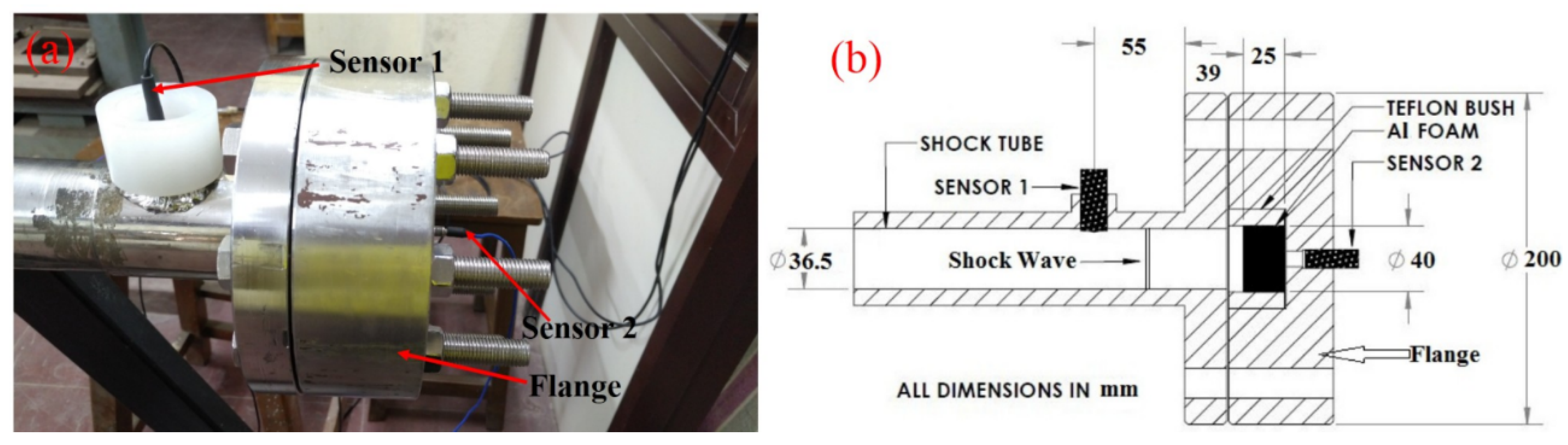
A single diaphragm shock tube with a circular section was used in the present investigation. The shock tube has a 50 mm inner diameter × 2 m long driver section, and a 36.5 mm inner diameter × 3 m long driven section, separated by 1.2 mm thick (t) aluminum diaphragm with a ‘t/3’ deep cross notch at the centre. Helium gas was pressurized in the driver section until the diaphragm ruptured. Air at atmospheric pressure was maintained in the driven section, through which the shock wave propagated on rupture of the diaphragm. The shock tube was instrumented with piezoelectric pressure sensors of model 102B04 and 102B of PCB Piezotronics (Depew, NY, USA), which had a rise time of less than a microsecond. A high-speed data acquisition system (NI PCI-6115 S, National Instruments, Austin, TX, USA) was used to acquire the pressure data. Sensor-1 (102B04) was mounted flush to the inner diameter of the shock tube at 94 mm distance from the front surface of the foam to measure the incident as well as reflected pressures (see Figure 1a,b).
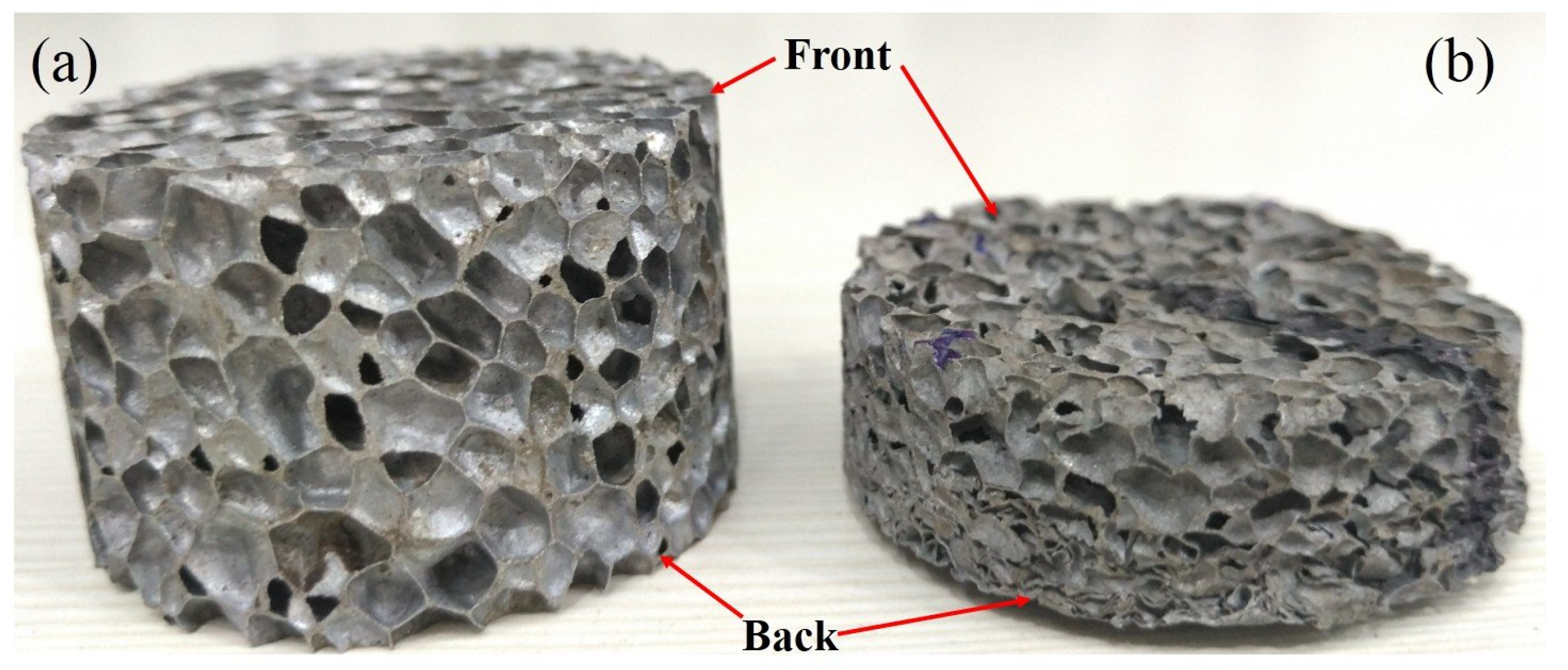
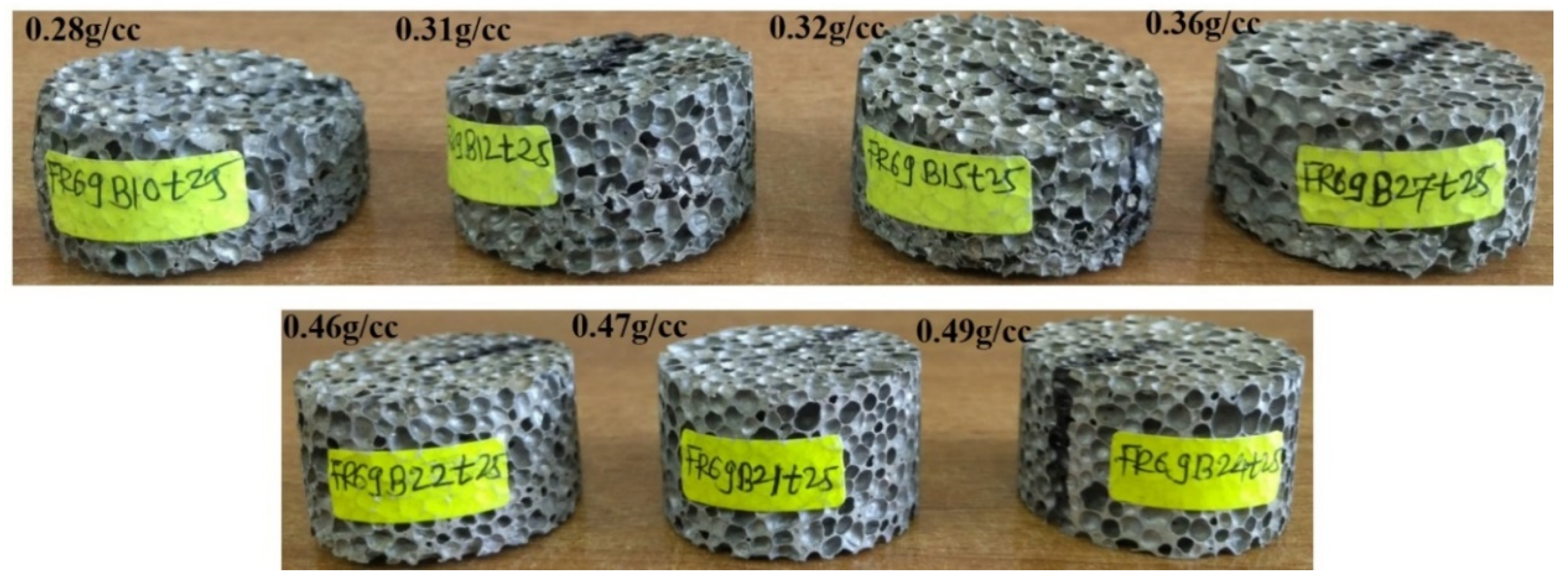
Closed cell aluminum foams were prepared in the form of cylindrical blocks by the melt route described elsewhere [18]. Since shock–foam interaction is sensitive to foam density [12], foams of incrementally varying densities from 0.28 to 0.49 g/cc were selected to capture the differences in their response to incident shock. Due to the inherent variability of foam density within the starting blocks, the density varied from sample to sample. Consequently, one experiment was done for each density but collectively, the samples covered a wide range of densities. Foam samples having a diameter of 40 ± 0.5 mm and thickness 25 ± 0.5 mm (Figure 2a), were mounted within a Teflon bush resting against the end-wall such that the back face of the foam was in full contact with the end-wall (see Figure 1b). The diameter of the foam was kept larger (by about 10%) than the shock tube ID to ensure that no material other than the foam lies in the path of the shock.
The end-wall of the shock tube was made of stainless steel having a centreline axial cavity of 9 mm dia running through the entire thickness of the flange. Sensor-2 (102B) was inserted through the axial cavity from behind the end-wall, resting about 2 mm away from the back surface of the foam. The hole allows the sensor to be recess-mounted such that it is not damaged during foam deformation on shock loading. Further, it is known that, if the end-wall has a hole of size smaller than a third of the shock tube diameter, the shock reflection at the end-wall is unaffected [19]. Due to this, and the fact that the sensor is placed very close to the exit (back/rear) face of the foam, the pressure-time history recorded by sensor-2 is expected to reveal the effects of compaction wave and flow filtration through the foam, on the ambience behind the foam [8,9]. A baseline experiment was carried out in the empty shock tube to measure the reflected pressure off the end-wall.
In a separate experiment, the speed of the shock wave was measured by recording the incident wave pressures at two locations separated by a distance of 474 mm in the driven section, and was found to be 1000–1050 m/s (more than Mach 3).
A scanning electron microscope (SEM) (Zeiss, GEMINI 300, Oberkochen, Germany) was used to examine the foam before and after the shock exposure. A 3-D X-ray microscope (3D CT) (Zeiss, VERSA 520, Oberkochen, Germany) was used to examine the internal structure of the foam before and after the shock tests.
3. Results and Discussions
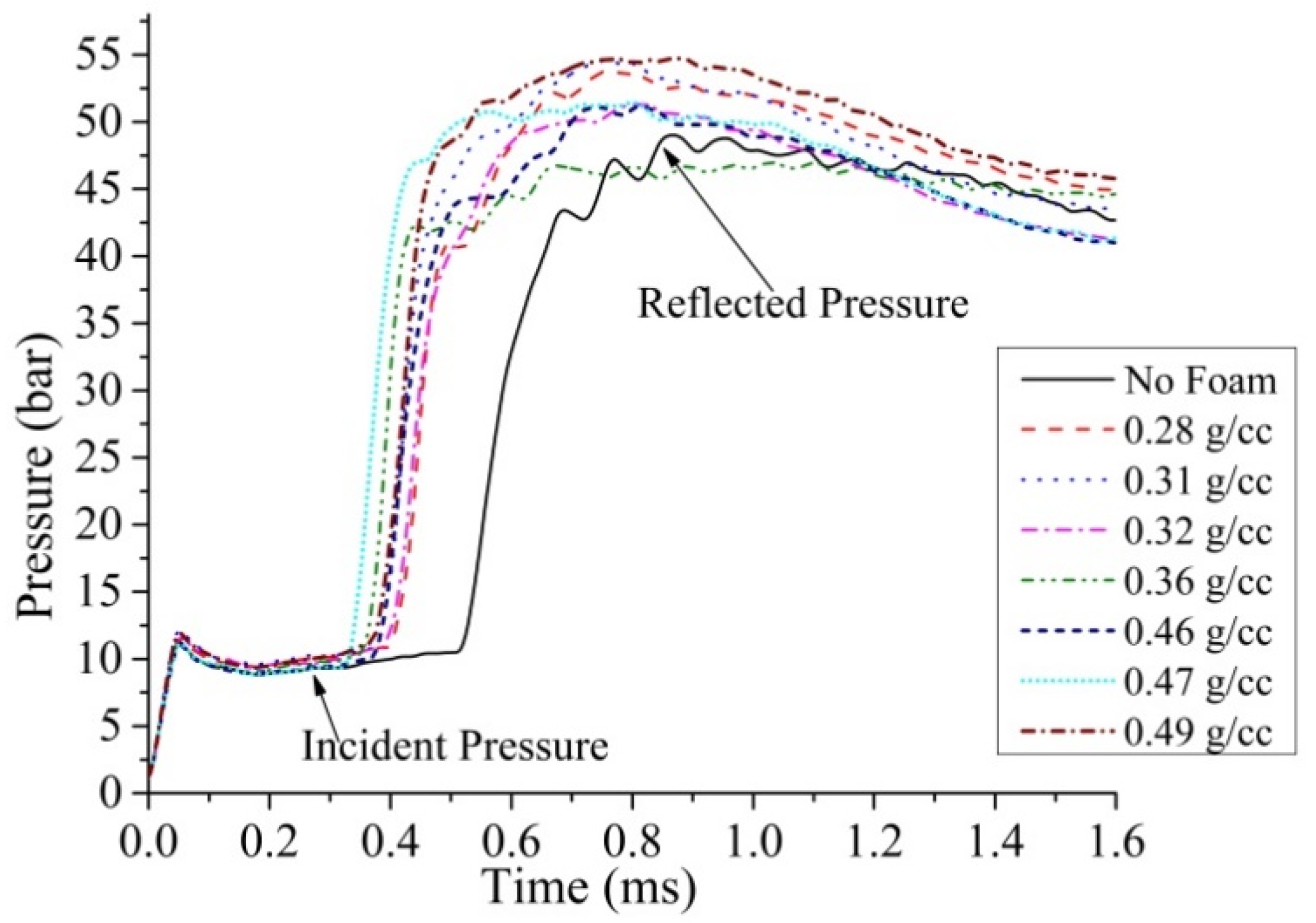
Figure 3 shows sensor-1 data for foams of various densities. A certain scatter in pressure values is seen, which is partly attributed to experimental variations in incident pressure (related to diaphragm rupture) and to morphological variations in the cell structure of the foam. In each case, pressure rises to its incident value, stays constant for about 0.3 ms, rapidly jumps to a higher value, and then rises at a reducing rate till reaching the maximum before slowly decreasing till the end of the measurement period. The incident pressure marks the arrival of the incident shock at sensor-1. As discussed by Britan et al. [8], the initial steep rise in reflected pressure is due to the arrival of the shock reflected from the foam front face, while the subsequent rise is attributed to additional shock reflections from the contact surface (driver-driven contact surface). For the empty tube (no foam) condition, the shock reflects from the end-wall of the tube. Table 1 gives numerical values of the incident pressures (the “plateau” values) and the reflected pressures measured by sensor-1 for foams of various densities and the empty shock tube.
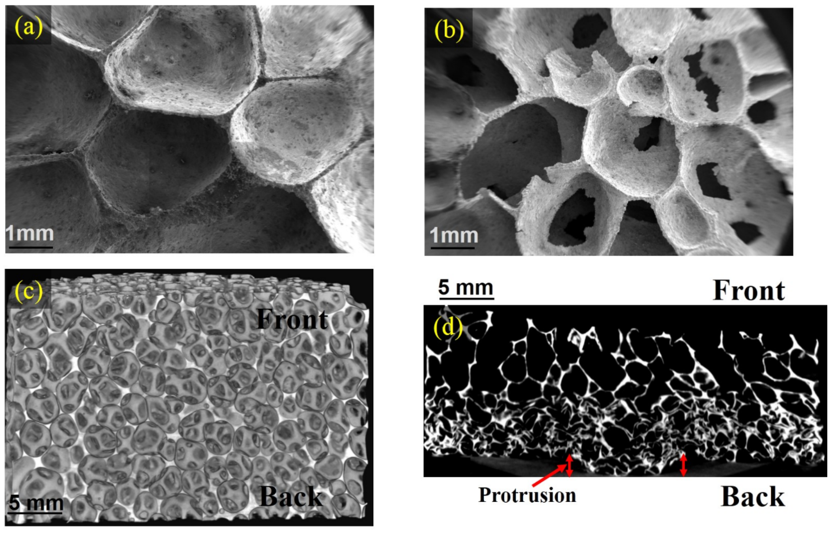
The shock exposed foams were seen to deform plastically, as shown in Figure 2b, where the total deformation (change in foam thickness) decreases with increasing foam density (Table 1 and Figure 4). Interestingly, the deformation in the foam samples was non-uniform along the length and always occurred from an intermediate location along the length (which was dependent on the foam density) extending up to the exit face. Another observation, being reported for the first time in shock–foam interaction literature, is the formation of perforations in cell walls due to shock exposure. The SEM image of the shock exposed foam in Figure 5b, when compared with 5a (unexposed) (both foams are of density 0.31 g/cc) clearly illustrates the perforation phenomenon. Although similar perforations have been observed in all the shock exposed foams, the perforation severity reduces with increasing foam density since the thickness of the cell wall increases with increasing density. The observation of the cell wall perforation is important since it creates the possibility of flow filtration through an otherwise closed cell foam. Figure 5c,d shows the 3D CT images of an unexposed and shock exposed foam sample, respectively, of 0.31 g/cc foam. The cell wall puncturing (Figure 5d) can be seen to continue to the subsurface region, which remains uncollapsed. The 3D CT images confirm that densification occurs towards the far end of the foam because the exit face is fully supported by the rigid end-wall (but for the cavity part). Unlike the observation of reference [13], no disintegration of the central portion of the foam nor radial cracks around the disintegrated region were observed in the foams after the tests, possibly because the foams were fully supported in the present work, as opposed to being simply supported in the referred work.
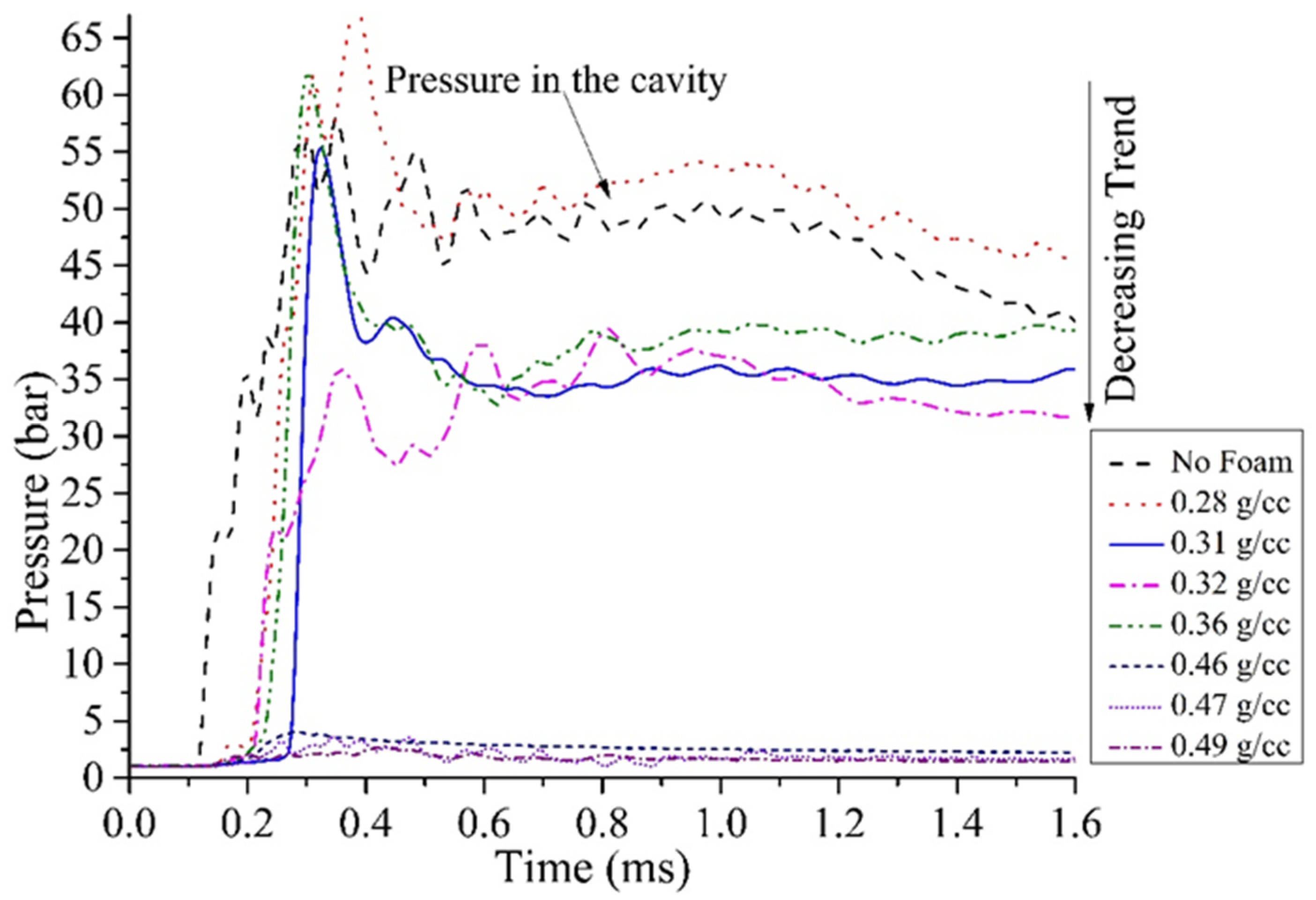
When the incident shock wave reflects off the surface of the foam, a compaction wave is generated in the foam. The compaction wave, on reaching the end of the foam, reflects off the end-wall, generating pressure/stress on the end-wall flange. A strong shock wave generated in water has been shown to transmit to air [10], and similarly from granular medium to air [8,9]. Figure 6 presents the variation of pressure in the air cavity in the end-wall of the shock tube, as measured by sensor-2, without and with the foams of various densities, fully supported against the end-wall. For the “no foam” condition (baseline value) as well as in the presence of foams of densities less than 0.46 g/cc, there is significant rise in pressure. In addition, the pressure rises sharply to a peak value indicating compaction wave transmission, drops to an intermediate value and then remains steady till the end of the measurement (1.6 ms). Table 1 gives the numerical values of the post-peak “steady” levels of the pressures behind the foam. Compared to the empty shock tube condition, the pressure in the cavity is almost the same in the presence of 0.28 g/cc foam [4], but reduces to 75% of the “baseline value” for 0.31–0.36 g/cc foams. When foams of density greater than 0.46 g/cc are present, the cavity pressure does not rise sharply, and the rise drops to 5% of the “baseline value” for 0.46 to 0.49 g/cc foams (shock mitigation). Thus, the present work shows that it is possible to attenuate shocks in small air-cavities by using closed cell aluminum foams of adequate density.
The compaction wave transmission stated above may require an extended explanation. A protrusion of the foam surface extending into the cavity was observed at the back of the shock exposed foam, as shown in Figure 5d, which is the means of shock transmission into air in the cavity. When the compaction wave reaches the back end of the foam, an acoustic impedance mismatch is realized at the cavity, as the cavity contains air. The mismatch of impedance at the foam–air interface reflects an unloading wave back into the foam in that region, as a result of which the foam extrudes into the air cavity. For the lower density foams, the sudden rise in air pressure in the cavity suggests that the extrusion must have been rapid, generating a piston effect, launching a shock wave. As this shock wave is generated by the foam by virtue of the compaction front in it, the wave is termed as a foam transmitted shock. The pressure rise and the rate at which it rises in the cavity depends on whether (and how quickly) the foam extrudes into the cavity which, in turn, depends on whether the reflected pressure exceeds the compressive strength of the foam. Since the compressive strength increases with foam density [1], while the reflected pressure changes only marginally, there is a critical density (between 0.36 to 0.46 g/cc) above which there is no extrusion and no sudden rise in cavity pressure.
The effect of foam density on the total compression can be explained by comparing the plastic strength of the foams with the incident and the reflected pressures. The plastic strength of foams under quasi-static compression is known to vary from about 2 MPa (20 bar) for 0.28 g/cc density to 5 MPa (50 bar) for 0.49 g/cc density [20]. Studies have variously shown that the plastic strength either remains unchanged [21,22,23,24] or increases with strain rate in the range 200–800 s−1 [25]. The pressure behind the reflected shock (from the foam front face) was of the order of 50 bar, which caused (an instantaneous) deformation and extrusion in lower density foams, which reduced with increasing foam density. The extent of cell wall perforation reduces with increasing foam density. This is to be expected as the foams of higher density have thicker cell walls and hence, a greater resistance to cell wall perforation.
In the early literature [5,6], plastic wave transmission and shock Hugoniot conditions were studied in dense porous aluminum with interconnected porosity, which is in contrast to the present work in which shock loading of closed cell aluminum foams containing 70–90% porosity, made by gassing liquid aluminum, was studied. Due to the high porosity and the high order of regular isotropic cell structure, the foam strength was several times lower in the current work. Thus, the behavior of the foams with respect to shock attenuation was observed to be different in the present study.
Recent work by Liang et al. [17] presented the effects of blast waves generated by 100 g TNT on two layers of aluminum foams sandwiched between steel plates. In the present work, a shock tube was used for shock wave generation and direct loading of single layer foams, which was amenable for the analysis of shock–material interactions and reflection waves. Therefore, here, densification was observed in the distal region of the foams, which was unseen in previous studies.
4. Conclusions
Aluminum foams of densities equal to or higher than 0.46 g/cc have been shown to attenuate shocks in cavities exposed to incident shock waves of Mach number 3. Incident shocks result in cell wall perforation in the front part of foam, bulk deformation in the rear part of the foam, and foam extrusion into the cavity placed in the end-wall that fully supports the foam, all reducing with increase in foam density. The shock experienced by the cavity is the foam-transmitted wave, due to the protrusion of the foam into the cavity, which is similar to the instantaneous acceleration of a piston in the air that generates a shock wave.
Author Contributions
Conceived and designed experiments: A.G., V.M., S.S. and M.T. Performed the experiments: M.T., V.M. and A.G. Analysed the data: M.T., V.M., A.G. and H.H. Contributed reagents/materials/analysis tools: A.G., S.S., V.M. and M.T. Wrote the paper: M.T., A.G., V.M., H.H. and S.S. All authors have read and agreed to the published version of the manuscript.
Funding
This research was funded by the Directorate of ER & IPR, DRDO, India, under grant No. RD/0117-DRDO000-002.
Acknowledgments
Authors thank Pramod Bhosale for his assistance in conducting the shock tube experiments.
Conflicts of Interest
The authors declare no conflict of interest.
References
- Ashby, M.F.; Evans, A.; Fleck, N.A.; Gibson, L.J.; Hutchinson, J.W.; Wadley, H.N.G. Metal Foams: A Design Guide, 1st ed.; Butterworth-Heinemann: Boston, MA, USA, 2000; pp. 150–170. [Google Scholar]
- Banhart, J. Manufacture, characterization and application of cellular metals and metal foams. Prog. Mater. Sci. 2001, 46, 559–632. [Google Scholar] [CrossRef]
- Mazor, G.; Ben-Dor, G.; Igra, O.; Sorek, S. Shock wave interaction with cellular materials: Part I: Analytical investigation and governing equations. Shock Waves 1994, 3, 159–165. [Google Scholar] [CrossRef]
- Ben-Dor, G.; Mazor, G.; Igra, O.; Sorek, S.; Onodera, H. Shock wave interaction with cellular materials: Part II: Open cell foams; experimental and numerical results. Shock Waves 1994, 3, 167–179. [Google Scholar] [CrossRef]
- Rempel, J.R.; Schmidt, D.N. Shock behavior of some non-reacting porous solids. In Proceedings of the Fourth International Symposium on Detonation, White Oak, MD, USA, 12–15 October 1965; pp. 266–276. [Google Scholar]
- Linde, R.K.; Schmidt, D.N. Shock propagation in nonreactive porous solids. J. Appl. Phys. 1966, 37, 3259–3271. [Google Scholar] [CrossRef]
- Petel, O.E.; Ouellet, S.; Higgins, A.J.; Frost, D.L. The elastic-plastic behaviour of foam under shock loading. Shock Waves 2013, 23, 55–67. [Google Scholar] [CrossRef]
- Britan, A.; Ben-Dor, G.; Elperin, T.; Igra, O.; Jiang, J.P. Gas filtration during the impact of weak shock waves on granular layers. Int. J. Multiph. Flow 1997, 23, 473–491. [Google Scholar] [CrossRef]
- Britan, A.; Ben-Dor, G.; Igra, O.; Shapiro, H. Shock waves attenuation by granular filters. Int. J. Multiph. Flow 2001, 27, 617–634. [Google Scholar] [CrossRef]
- Hosseini, H.; Moosavi-Nejad, S.; Akiyama, H.; Menezes, V. Shock wave interaction with interfaces between materials having different acoustic impedances. Appl. Phys. Lett. 2014, 104, 1–5. [Google Scholar] [CrossRef]
- Schenker, A.; Anteby, I.; Gal, E.; Kivity, Y.; Nizri, E.; Sadot, O.; Michaelis, R.; Levintant, O.; Ben-Dor, G. Full-scale field tests of concrete slabs subjected to blast loads. Int. J. Impact Eng. 2008, 35, 184–198. [Google Scholar] [CrossRef]
- Goel, M.D.; Altenhofer, P.; Matsagar, V.A.; Gupta, A.K.; Mundt, C.; Marburg, S. Interaction of a shock wave with a closed cell aluminium metal foam. Combust. Explos. Shock Waves 2015, 51, 373–380. [Google Scholar] [CrossRef]
- Reddy, C.J.; Madhu, V. Dynamic behaviour of foams and sandwich panels under shock wave loading. Procedia Eng. 2017, 173, 1627–1634. [Google Scholar] [CrossRef]
- Kazemi-Kamyab, V.; Subramaniam, K.; Andreopoulos, Y. Stress transmission in porous materials impacted by shock waves. J. Appl. Phys. 2011, 109, 1–18. [Google Scholar] [CrossRef]
- Liu, H.; Cao, Z.K.; Yao, G.C.; Luo, H.J.; Zu, G.Y. Performance of aluminum foam-steel panel sandwich composites subjected to blast loading. Mater. Des. 2013, 47, 483–488. [Google Scholar] [CrossRef]
- Hanssen, A.G.; Enstock, L.; Langseth, M. Close-range blast loading of aluminium foam panels. Int. J. Impact Eng. 2002, 27, 593–618. [Google Scholar] [CrossRef]
- Liang, M.; Li, X.; Lin, Y.; Zhang, K.; Lu, F. Dynamic compressive behaviors of two-layer graded aluminum foams under blast loading. Materials 2019, 12, 1445. [Google Scholar] [CrossRef] [PubMed] [Green Version]
- Miyoshi, T.; Itoh, M.; Akiyama, S.; Kitahara, A. Aluminum foam, “alporas”: The production process, properties and applications. In Proceedings of the Symposium on Porous and Cellular Materials for Structural Applications, San Francisco, CA, USA, 13–15 April 1998; Volume 521, pp. 133–137. [Google Scholar]
- Hornung, H.G.; Belanger, J. Role and techniques of ground testing for simulation of flows up to orbital speed, AIAA 90-1377. In Proceedings of the AIAA 16th Aerodynamic Ground Testing Conference, Seattle, WA, USA, 18–20 June 1990. [Google Scholar]
- Gibson, L.J.; Ashby, M.F. Cellular Solids: Structure and Properties, 2nd ed.; Cambridge University Press: Cambridge, UK, 1997; pp. 309–343. [Google Scholar]
- Peroni, M.; Solomos, G.; Pizzinato, V. Impact behaviour testing of aluminium foam. Int. J. Impact Eng. 2013, 53, 74–83. [Google Scholar] [CrossRef]
- Deshpande, V.S.; Fleck, N.A. High strain rate compressive behaviour of aluminium alloy foams. Int. J. Impact Eng. 2000, 24, 277–298. [Google Scholar] [CrossRef] [Green Version]
- Schüler, P.; Fischer, S.F.; Bührig-Polaczek, A.; Fleck, C. Deformation and failure behaviour of open cell Al foams under quasistatic and impact loading. Mater. Sci. Eng. A 2013, 587, 250–261. [Google Scholar] [CrossRef]
- Atturan, U.A.; Nandam, S.H.; Murty, B.S.; Sankaran, S. Deformation behaviour of in-situ TiB2 reinforced A357 aluminium alloy composite foams under compressive and impact loading. Mater. Sci. Eng. A 2017, 684, 178–185. [Google Scholar] [CrossRef]
- Islam, M.A.; Brown, A.D.; Hazell, P.J.; Kader, M.A.; Escobedo, J.P.; Saadatfar, M.; Xu, S.; Ruan, D.; Turner, M. Mechanical response and dynamic deformation mechanisms of closed-cell aluminium alloy foams under dynamic loading. Int. J. Impact Eng. 2018, 114, 111–122. [Google Scholar] [CrossRef]
Figure 1.
(a) Stainless steel flange of the shock tube for mounting foam samples. (b) Details of foam and sensor placement inside the flange.
Figure 1.
(a) Stainless steel flange of the shock tube for mounting foam samples. (b) Details of foam and sensor placement inside the flange.

Figure 2.
Aluminum foam samples (a) before and (b) after shock exposure.

Figure 3.
Variation of incident and reflected shock pressures with time (sensor-1).

Figure 4.
Aluminum foam samples of increasing foam density after shock exposure.

Figure 5.
The SEM and 3D CT images of the foam of density 0.31 g/cc. (a) SEM SE image of the front surface before shock exposure, (b) SEM SE image of the front surface after shock exposure, (c) 3D CT view before shock exposure, and (d) 3D CT view after shock exposure.
Figure 5.
The SEM and 3D CT images of the foam of density 0.31 g/cc. (a) SEM SE image of the front surface before shock exposure, (b) SEM SE image of the front surface after shock exposure, (c) 3D CT view before shock exposure, and (d) 3D CT view after shock exposure.

Figure 6.
Variation of transmitted wave pressure with time in the air cavity (sensor-2) in the presence of various density foams and, without any foam (baseline).
Figure 6.
Variation of transmitted wave pressure with time in the air cavity (sensor-2) in the presence of various density foams and, without any foam (baseline).


Table 1.
Effect of foam density on foam plastic deformation and shock pressures.
| Density (g/cc) | Plastic Deformation (mm) | Incident Pressure (Sensor-1) (bar) | Reflected Pressure (Sensor-1) (bar) | Pressure in the End-Wall Cavity (Sensor-2) (bar) |
|---|---|---|---|---|
| No Foam | - | 10.3 | 49.5 | 51.5 |
| 0.28 | 9.3 | 10.3 | 52.1 | 52.5 |
| 0.31 | 5.9 | 10.3 | 51.0 | 36.0 |
| 0.32 | 5.78 | 10.7 | 52.2 | 35.1 |
| 0.36 | 4.44 | 9.7 | 46.6 | 38.8 |
| 0.46 | 1.75 | 9.7 | 48.8 | 3.3 |
| 0.47 | 0.75 | 9.8 | 50.1 | 2.7 |
| 0.49 | 0.55 | 9.7 | 54.4 | 2.7 |
© 2020 by the authors. Licensee MDPI, Basel, Switzerland. This article is an open access article distributed under the terms and conditions of the Creative Commons Attribution (CC BY) license (http://creativecommons.org/licenses/by/4.0/).
Share and Cite
MDPI and ACS Style
Thorat, M.; Sahu, S.; Menezes, V.; Gokhale, A.; Hosano, H. Shock Loading of Closed Cell Aluminum Foams in the Presence of an Air Cavity. Appl. Sci. 2020, 10, 4128. https://doi.org/10.3390/app10124128
AMA Style
Thorat M, Sahu S, Menezes V, Gokhale A, Hosano H. Shock Loading of Closed Cell Aluminum Foams in the Presence of an Air Cavity. Applied Sciences. 2020; 10(12):4128. https://doi.org/10.3390/app10124128
Chicago/Turabian StyleThorat, Mahesh, Shiba Sahu, Viren Menezes, Amol Gokhale, and Hamid Hosano. 2020. "Shock Loading of Closed Cell Aluminum Foams in the Presence of an Air Cavity" Applied Sciences 10, no. 12: 4128. https://doi.org/10.3390/app10124128
Note that from the first issue of 2016, this journal uses article numbers instead of page numbers. See further details here.