
CAD-MBSE Interoperability for the Checking of Design Requirements Based on Assemblability Indicators


1
Mechanical Engineering Laboratory, National Engineering School of Monastir, University of Monastir, Ibn Eljazzar, Monastir 5019, Tunisia
2
Quartz Laboratory, ISAE-Supmeca, 3 Rue Fernand Hainaut, 93400 Saint-Ouen, France
*
Author to whom correspondence should be addressed.
Appl. Sci. 2022, 12(2), 566; https://doi.org/10.3390/app12020566
Submission received: 14 December 2021
/
Revised: 1 January 2022
/
Accepted: 4 January 2022
/
Published: 7 January 2022
Abstract
:A mechanical product is the result of collaboration between different domains. In this paper we focus on the collaborative work that brings together the system engineer and the designer in the realization process of a mechanical system. A design solution, conceived in the CAD environment, is considered valid if all the specification requirements, defined in the MBSE (Model Based System Engineering) domain, are met. Thus, the preliminary study of these requirements has a major influence on the choice and validation of the design solution. In this paper a methodology for handling the requirements has been detailed. These requirements are classified into two main categories. The first one deals with the product performance and the second addresses the process performance in order to generate the best assembly sequence. Depending on the response of the designed solution to these requirements, it becomes easy to decide not only whether the design solution can be validated or not but also to choose the most optimal assembly sequence that ensures the best operation quality. A validation example of a speed reducer is used to demonstrate the added value of the proposed approach.
1. Introduction and State of the Art
The search for the right compromise between cost, quality and production time has led researchers to better contribute to technological development. This in turn led to the development of highly complex systems [1]. Among them we can cite mechanical systems. Their complexity appears not only in the complexity of parts but also in the difficulty of finding the most optimal assembly sequence that leads to a highly quality of the product. The accumulation of all these requirements from different fields makes the task of validating the final product more difficult. For this reason, good collaboration between all disciplines is essential [2]. This concentration of efforts helps to produce valid systems that strive for perfection [3]. Model-Based Systems Engineering (MBSE) is a multi-disciplinary approach that facilitates the exchange between different domains to validate systems design [4]. SysML is one of the languages used by System Engineer (SE) to document requirements in order to describe the overall solution in a simple and efficient way [5]. Thus, the MBSE approach using Systems Modeling Language (SysML) is a good choice for system design to better manage all the constraints [6,7]. Currently the problem is how to ensure the exchange of data between the SE, who has a global view of the product, and the designer, who is a Computer Aided Design (CAD) specialist, in order to validate the design solution of the mechanical assembly and to define the most appropriate assembly sequence that allows for a better quality.
Several research works focused on the development of MBSE and CAD. However, little works treated the interconnection between these two engineering domains to assess the response of mechanical systems by involving SE in the choice of the design solution [4]. Indeed, to solve the problem of the assembly sequences generation, researchers initially relied on the philosophy of determining disassembly sequences. The assembly plans are considered, thus, as the reverse order of the disassembly sequences. However, this philosophy has met with many counter examples [8]. Therefore, the second philosophy focuses on the determination of assembly plans directly without going through the reverse path. Bourjault is considered the first to develop an approach for determining all possible assembly sequences of a product [9]. Other researchers generated the assembly sequences based on a simplification of the assembly model by eliminating the connecting parts [10,11]. There is also Wolter who proposed an approach that allows the generation of a single assembly sequence by respecting the following criteria: the trajectories of the operation, the handling of the component, and the tools used for the assembly [12]. The generation of assembly sequences is certainly an important step in the development phase of mechanical systems, but it is always necessary to choose the most optimal sequence to ensure proper operation and better profitability of the system. To this end, Design For Assembly (DFA) methodologies have been very successful in improving product assemblability [13]. In the literature, several DFA methodologies have been studied but the most extensive are those of Boothroyd and Dewhurst [14], Lucas methodology [15], Modified Westinghouse methodology [16], and Hitachi-AEM methodology [17]. Other research studies have combined the 4 methodologies mentioned above to come up with a methodology that allows the product development method to be reinforced in all phases of the design process [18]. However, these methodologies do not allow the study of product design problems at the beginning of the product life cycle, so researchers have proposed new analysis indicators to determine the correct assembly sequences from a ranked list [19]. In the same context, a new approach using essential metrics to define optimal assembly sequences were developed [20]. Another persisting problem is the problem of generating of CAD data. Indeed, to solve the problem of data exchange between the CAD system and CAD applications, a tool called CADLAB that ensures the extraction of CAD data from mechanical assemblies were developed [21].
In the MBSE environment, some researchers are interested in defining the functional architecture of products, which facilitates the definition of system requirements and makes it easier to understand [22]. Similarly, a methodology that consists of two phases of analysis of the internal and external architecture of a mechatronic system in order to reduce systems complexity were developed [23]. In the MBSE environment the validation stage plays a key role in testing whether the proposed system will meet the customer’s needs or not. To this end, Selvy et al. used SysML to verify and validate the planning on the Large Synoptic Survey Telescope (LSST) [24]. In order to improve the tools used by systems engineers, some researchers addressed the limitations of SysML [25].
During the last few years, researchers have felt the major importance of communication between engineers to ensure a good understanding of the systems, which helps to produce satisfactory systems that meet all needs. Brahmi et al. developed a SysML profile capable of reading assembly data from the CAD software tree and translating them into SysML data [1]. They also defined a methodology to ensure continuity of work between SE and designers to facilitate the validation of proposed design solutions [4]. In the same theme, a methodology that enriches the CAD database with functional information collected from the MBSE area were developed [26].
2. Synthesis and Main Objectives
From the previous literature review, it can be concluded that research works are under development but each one separately. The main limitations of the ongoing research are as follow:
- ▪
- Remarquable communication discontinuity between SE and designers.
- ▪
- Retained product solutions do not fulfill to all system-engineering requirements.
- ▪
- No conformity of the product with specifications.
To remedy these limitations, this paper presents an automatic validation approach of design requirements. The proposed approach is based on a set of assemblability indicators which represent the assembly performances.
3. Proposed Approach
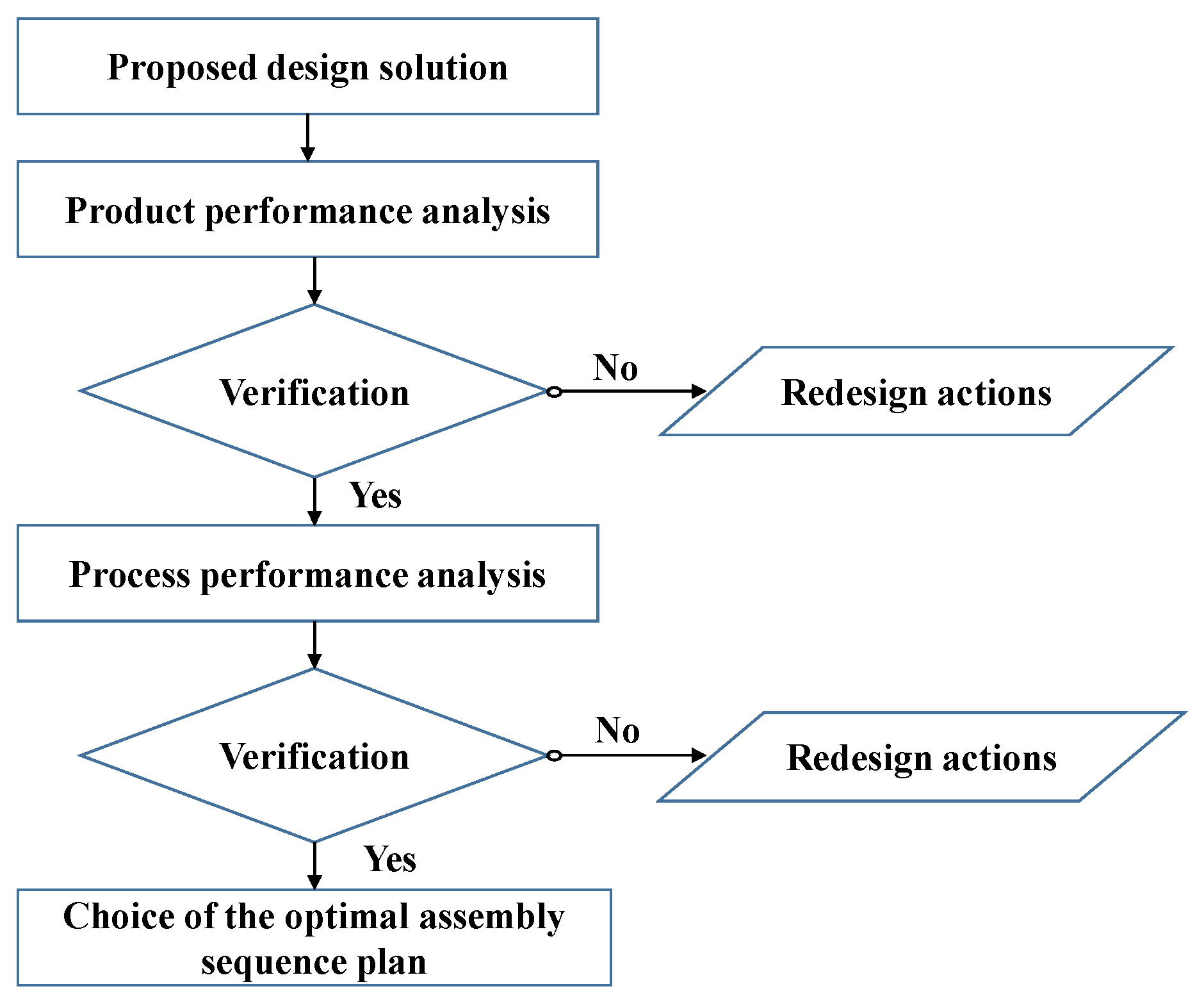
The proposed methodology illustrated in Figure 1 deals with the realization process of mechanical system from the functional analysis phase until the validation. Subsequently, this methodology allows the selection of the most optimal assembly sequence based on the response of the design solution to some assemblability indicators. The approach defines a bridge of exchange between the two domains of MBSE and CAD and integrates the SE in the validation of the design solution, a task that was previously dedicated only to designers. This methodology ensures a qualitative mechanical design that meets all requirements, which has an impact on the manufacturing cost and production time of the mechanical systems produced afterwards.
In the following, each step of the methodology will be detailed and illustrated by a case study example which is a planetary gear for speed reduction. Figure 2 illustrates the treated mechanism. The cycloidal speed reducer is a mechanism that serves to reduce the input speed of a motor shaft by achieving relatively high ratios in compact sizes with very small clearances.
3.1. Functional Analysis and Requirements Definition
Understanding the use context of each product is essential in order to be able to describe the requirements to satisfy. Thus, gathering all the informations about the use purpose will increase the design efficiency and ultimately lead to the development of a winning product. This is the purpose of the functional analysis step, which is the key to define all the product requirements before developing design solutions. Consequently, the first step of the proposed methodology, is an essential step as it allows to deconstruct the customer need and to express all the requirements related to their satisfaction.
This step is carried out in the MBSE domain where the SE is asked to fix all the requirements to be satisfied by the mechanical system. Once identified and characterised this will subsequently help to test the response of the designed solution to these requirements and measure its progress and success against the defined objective criteria. This step is a very interesting and important one in the project management process, which avoids some of the classic design pitfalls and enables dialogue between the designer and the SE. It is a guarantee of objectivity and creativity in the management of the project.
All the requirements are represented in a SysML requirements diagram. Among them, there are those related to the design assemblability. These requirements are classified into two categories and a calculation indicator is assigned to each of them. The classification of these assemblability indicators is as follows:
- ▪
- Product performance indicators: Their values remain invariant even when changing the assembly sequences. Used to judge whether the designed solution is valid and indicates the possibility of improving the design.
- ▪
- Process performance indicators: Their values change by changing the assembly sequence. Thus, used to help in the determination of the most optimal assembly sequence among a list of sequences.
In this phase, eight assembly indicators (Table 1) are proposed for inclusion in the requirements document for each mechanical system. A detailed analysis of these indicators allows SE to progressively focus on tasks that require improvement. It is noticed that the boundary values of these indicators are either defined by the working group or imposed by the SE depending to the treated mechanism.
3.1.1. Product Performance
Several researchers have developed methodologies and analysis tools to improve assembly during the development phase of mechanical systems. According to the predefined principle, the product performance indicators are used to quantify the quality of the proposed solution and indicate whether the latter needs improvement. For each indicator, a limit value is assigned. These values serves to allow their comparison to those calculated for each designed solution. The indicators used for the product performance analysis are: maximum number of parts (N), cost (C), efficiency (De) and are calculated using Equations (1)–(3). These equations as follows:
where
- A: Essential components;
- B: Non-essential components;
- N: total number of parts;
- Ck: Part assembly cost.
It is noticed that all parts are classified into essential (A) and non-essential parts (B) according to the working group and based on the answer to the subroutine shown in Figure 3.
Based on an in-depth needs study of each mechanical system under consideration, the SE defines limit values for the product performance indicator in a requirement diagram. These values serve to judge the validity of the design solution later on. The product performance requirements of the speed reducer are represented in Figure 4.
3.1.2. Process Performance
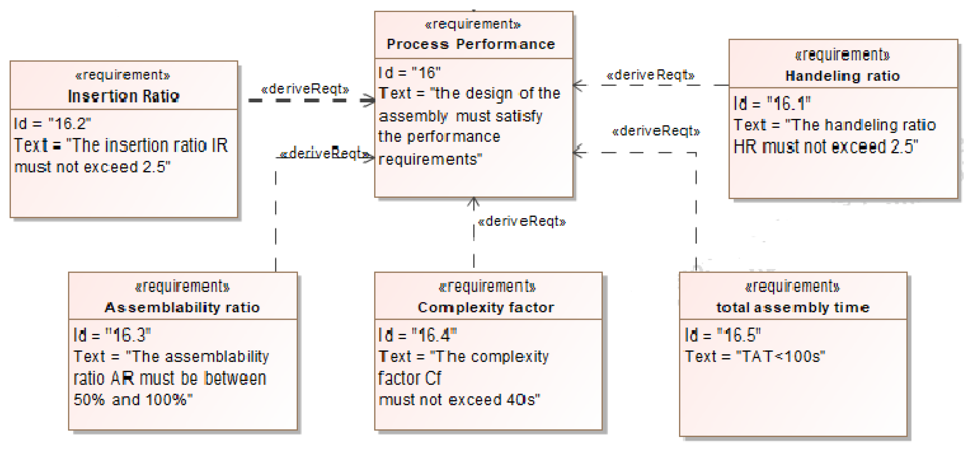
As well as the product performance indicators, the process indicators also need to be studied. As they are time dependent, their values change as the assembly sequence changes. The process performance indicators are used to determine which assembly sequence offers the best operation quality. The indicators studied in this paper are: total assembly time (TAT), insertion ratio (IR), handling ratio (HR), assemblability ratio (AR) and complexity factor (CF). These process performance indicators are formulated by Equations (4)–(8). The process performance requirements defined for the speed reducer example are modeled in Figure 5. It is noticed that the working group gives the limit values of each indicator. For example, the design efficiency (De) value must exceed 60% for the case study.
where
- Ti: insertion time.
- TH: handeling time.
- NUP: the amount of unrepeated essential parts (A).
- : Minimum assembly time in the industry’s assembly line.
Figure 5.
Process performance requirements of the speed reducer.

3.1.3. XML-MBSE Data Generation
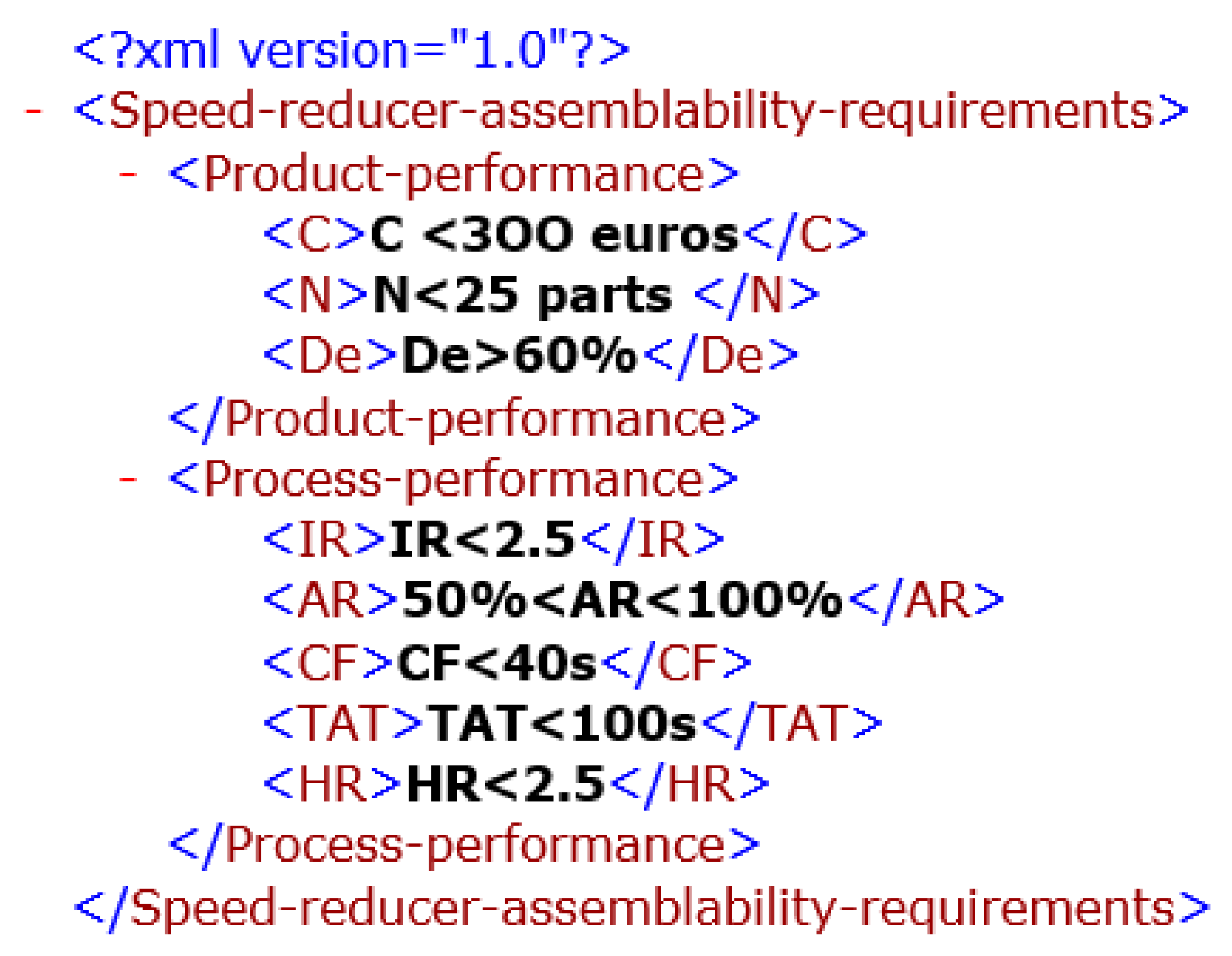
The data exchange between disciplines from different specialities can be the cause of huge problems due to use of different languages. Indeed, the lack of standard means of communication between them can lead to misunderstanding or loss of informations. This can obviously result in systems with poor quality that do not meet requirements. The data exchange phase is therefore essential to ensure the fully transfer of informations. Therefore, during this stage, the data generation is performed in Extensible Markup Language (XML) format for its simplicity and to allow the easily translation of all the previously studied informations. The resulting file contains a summary of the boundary values of the assemblability indicators fixed by the SE and needed by the designer during the design phase in order to produce a satisfactory design solution that meets all the requirements.
The XML-MBSE data generation file for the speed reducer example is represented in Figure 6.
3.2. 3D Design and Assembly Sequences Generation
3.2.1. 3D CAD Development
The collaborative work between the designer and the SE takes place at this stage. The CAD domain enables an idea extracted from a customer requirement to be transformed into an industrialisable object based on design techniques and methods. Thus, the designer is responsible for transforming the ideas and requirements of the SE into a useful product design. Based on the data collected from the MBSE domain defined in the XML file, the designer propose and design the most suitable solution that can meet all the customer needs.
In this step, the CAD specialist creates three-dimensional mechanical parts with their properties i.e., dimensions, mechanical strength, type of materials etc. This obviously gives a global visibility of the behaviour of a part before it exists, in terms of its appearance and its structure and functioning. This stage gives also the opportunity for the designer to refer to each constituant if any changes are required. At the end of the designers work, the plans of each part and all the dimensions that characterize them are modeled.
3.2.2. Assembly Sequence Generation
During this step and based on the designed solution, the designer is asked to define all the possible Assembly Sequence Plans (ASP) for the proposed design. The purpose of this step is to detail all the possible assembly solutions in order to select the most satisfactory sequence later. Based on the work detailed in [10], three possible assembly sequences (ASP1, ASP2 and ASP3) of the speed reducer are summarized in Table 3.
3.2.3. CAD XML Generation
After developing a detailed design and generating all the possible assembly sequences, and similar to the generation of MBSE data, CAD data need also to be described in a simple and efficient way in an XML file that summarizes the designers contribution. This will help the SE, a non-CAD specialist, to understand the work previously elaborated in the CAD domain in order to check the design solution response to requirements.
3.2.4. Analysis and Validation
The importance of the collaborative work between the designer and the SE appears in this step. It is at this stage that the designed solution may be judged satisfactory or not. The SE is involved in the validation of the design solution proposed in CAD domain. After receiving the CAD-XML file, the proposed design solution should be analyzed based on its response to the initially defined requirements. Thus, if all the requirements are validated, the solution is considered satisfactory and the manufacturer takes over. If not, a report detailing the non-reconciled requirements should be sent back to the designer with the aim of making the appropriate changes.
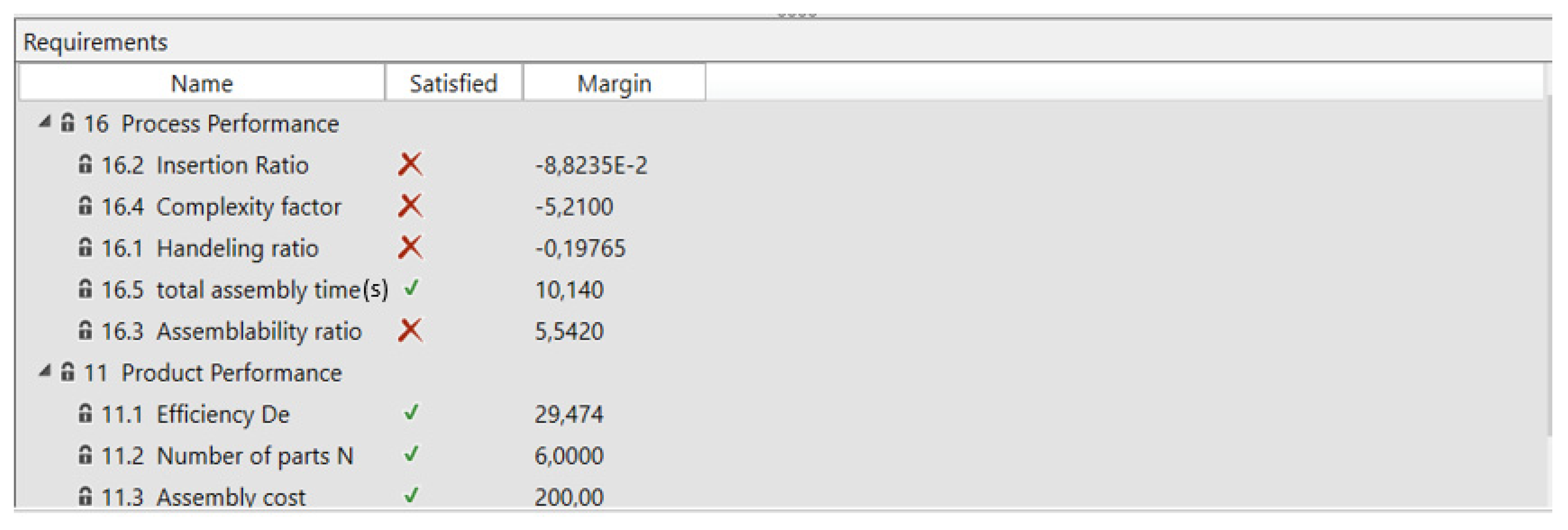
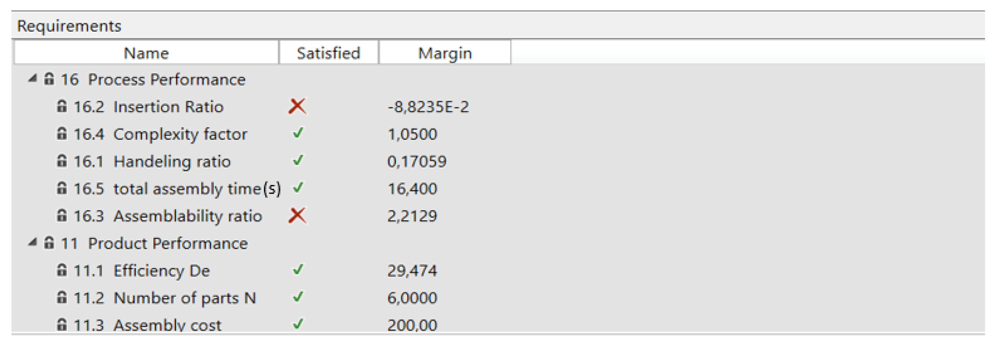
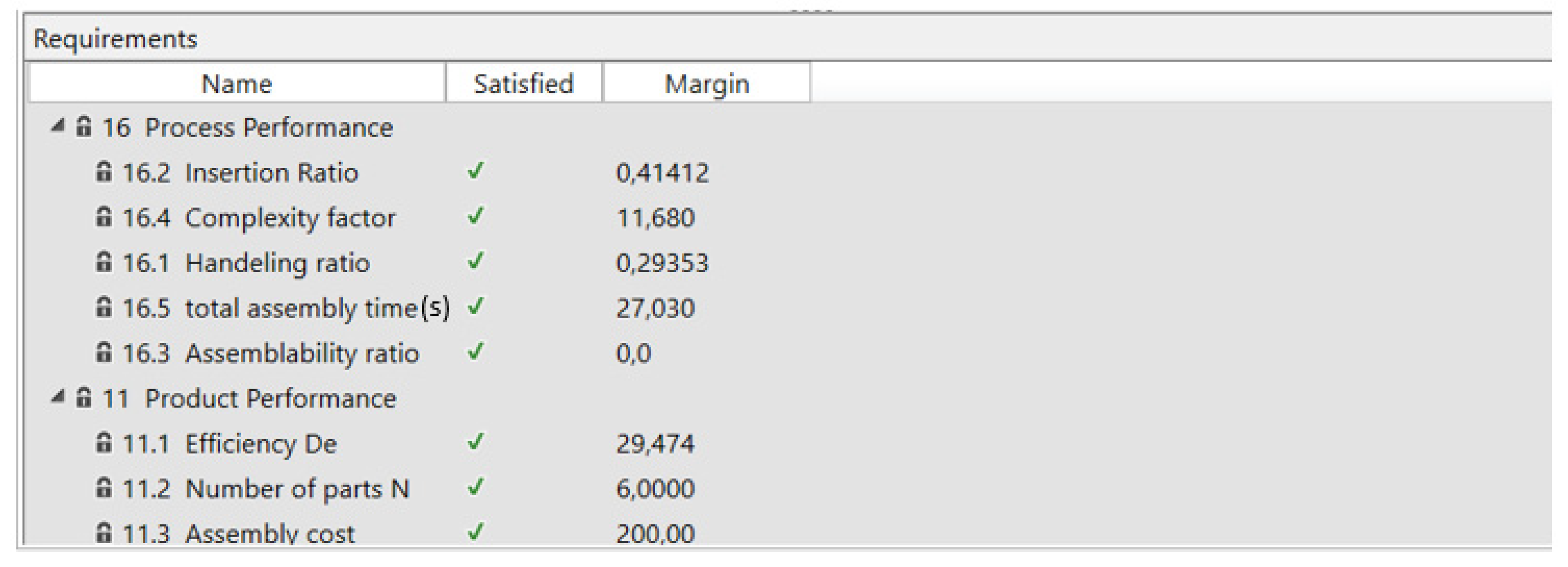
Figure 8 illustrates the analysis methodology. The first step is to analyse the product performance indicators of the proposed design solution. If their values are in line with those of the initially defined requirements, then the product performance is deemed satisfactory. If not, an analysis report should be sent to the designer to make the appropriate changes. The next step is to analyse the process performance indicators for each assembly sequence separately, and to test their response to the specification requirements. Based on the results of the analysis, the SE can select the best assembly sequence that meets all the requirements and offer a higher quality. Given the predefined criteria, it is very rare to have two assembly sequences with the same score. However, if the system engineer ends up with several acceptable ASPs then the designers team will choose the most optimal solution. For the speed reducer example, the analysis of the design solution is carried out using Modelcenter MBSE connection tool, which connects the requirements stored in Magicdraw software in the requirement diagram to the analysis indicators values for the proposed solution. Figure 9, Figure 10 and Figure 11 shows the responses of ASP1, ASP2 and ASP3 to the initial requirements respectively.
4. Results and Discussion
The outcomes of the proposed methodology are as follows:
- Requirement definition: in this step the SE identifies all the requirements and assigns limit values for the product performance and process performance indicators.
- CAD development: in this stage the designer proposes an adequate design solution and generates all the possible assembly sequences.
- Validation and choice of the appropriate assembly sequence: during this stage the SE analyses the designed solution and compares its response to the initially defined requirements to judge whether it is acceptable in order to select the most optimal assembly sequence.
Designing in the shortest possible time, with the least expense and the best quality remains a constant challenge for designers. By combining product performance and process performance metrics, the proposed methodology allows a good evaluation of the designed solution with an optimal assembly sequence. Based on the results of the Figure 9, Figure 10 and Figure 11, all the product performance indicators are satisfied. Indeed, the designed solution perfectly meets the SE expectations and the calculated values are in concordance with the system specifications. This implies that the design solution can be required if the process performance requirements are also met.
Based on the methodology detailed in Figure 8, as the product performance indicators were validated the SE should move on to the analysis of the process indicators. Thus, ASP1 and ASP2 of the treated example does not meet the threshold values of some assemblability indicators as indicated in Figure 9 and Figure 10. As a result, these two assembly sequences are not acceptable. In contrast to ASP3, all the requirements are marked in green (Figure 11), which implies that the requirements are fully met.
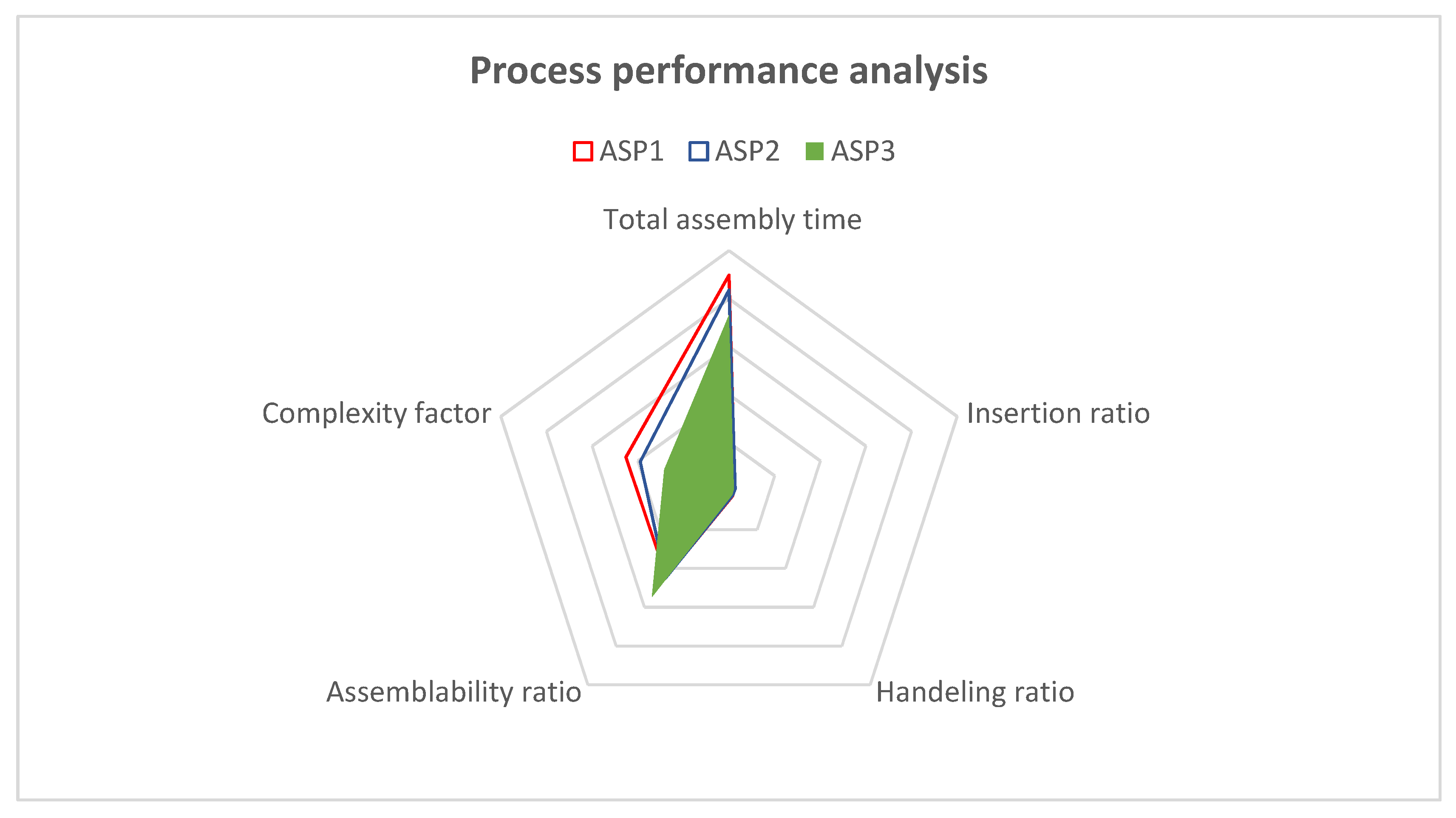
Since the SE is looking to minimize as much as possible the values of the indicators TAT, IR, HR, CF and to have a value of AR between 50 and 100%, then according to Figure 12, ASP3 is the sequence with the smallest surface area compared to ASP1 and ASP2, which reflects the choice of ASP3 as the best assembly sequence.
5. Conclusions and Future Works
Interoperability between SE and designers plays an important role in ensuring the production of high mechanical assemblies quality. In this paper, a methodology that proposes the necessary steps to preserve the continuity of communication between them were developed. This methodology allows testing the response of a proposed CAD design solution to the requirements defined in the MBSE based on a set of assemblability indicators. Based on these requirements, the SE participates in the choice of the most appropriate assembly sequences, which were previously the responsibility of the designer. Subsequently, the proposed approach helps to measure the quality of the design, facilitate the identification of assembly problems and significantly increases the quality of the products to be developed. The main objective is to minimize damage and problems before embarking on the manufacturing phase.
In future work, the developed approach can be improved by promoting the automated validation step. Furthermore, an implementation of an automatic conversion between the two domains using a graphic user interface is under development.
Author Contributions
Conceptualization, R.B., I.B., M.H., N.A. and J.-Y.C.; methodology, R.B., I.B., M.H., N.A. and J.-Y.C.; validation, I.B., M.H., N.A. and J.-Y.C.; formal analysis, I.B., M.H., N.A. and J.-Y.C.; investigation, R.B.; resources, R.B.; writing—original draft preparation, R.B.; writing—review and editing, R.B., I.B., M.H., N.A. and J.-Y.C.; supervision, I.B., M.H., N.A. and J.-Y.C.; project administration, J.-Y.C. and N.A. All authors have read and agreed to the published version of the manuscript.
Funding
This research was funded within the Partnership Hubert Curien “PHC Utique” of the French Ministry of Europe and Foreign Affairs, and the Tunisian Ministry of Higher Education and Scientific Research (CMCU 21G1112). The authors gratefully acknowledge their financial support.
Institutional Review Board Statement
Not applicable.
Informed Consent Statement
Not applicable.
Acknowledgments
This work is carried out within the Partnership Hubert Curien “PHC Utique” of the French Ministry of Europe and Foreign Affairs, and the Tunisian Ministry of Higher Education and Scientific Research (CMCU 21G1112). The authors gratefully acknowledge their financial support.
Conflicts of Interest
The authors declare no conflict of interest.
References
- Brahmi, R.; Hammadi, M.; Choley, J.-Y.; Trigui, M.; Aifaoui, N. A SysML profile for mechanical assembly. In Proceedings of the 2020 IEEE International Systems Conference (SysCon), Montreal, QC, Canada, 24 August–20 September 2020; pp. 1–7. [Google Scholar]
- Fradi, M.; Gaha, R.; Mlika, A.; Mhenni, F.; Choley, J.Y. Design of an Electronic Throttle Body Based on a New Knowledge Sharing Engineering Methodology. In Advances in Mechanical Engineering and Mechanics II; Springer: Berlin/Heidelberg, Germany, 2020; pp. 55–63. [Google Scholar]
- Brahmi, R.; Hammadi, M.; Aifaoui, N.; Choley, J.-Y. CAD-MBSE interoperability for the checking of design requirements. In Proceedings of the 2021 18th International Multi-Conference on Systems, Signals & Devices (SSD), Monastir, Tunisia, 22–25 March 2021; pp. 1446–1451. [Google Scholar]
- Brahmi, R.; Hammadi, M.; Aifaoui, N.; Choley, J.-Y. Interoperability of CAD models and SysML specifications for the automated checking of design requirements. Procedia CIRP 2021, 100, 259–264. [Google Scholar] [CrossRef]
- Ii, C.A.E. System Hazard Analysis. In Hazard Analysis Techniques for System Safety; John Wiley & Sons, Ltd.: Hoboken, NJ, USA, 2005; pp. 115–129. [Google Scholar]
- OMG SysML Home | OMG Systems Modeling Language. Available online: https://www.omgsysml.org/ (accessed on 13 December 2021).
- Mhenni, F.; Choley, J.-Y.; Rivière, A.; Nguyen, N.; Kadima, H.; Mhenni, F. SysML and safety analysis for mechatronic systems. In Proceedings of the 2012 9th France-Japan & 7th Europe-Asia Congress on Mechatronics (MECATRONICS)/13th Int’l Workshop on Research and Education in Mechatronics (REM), Paris, France, 21–23 November 2012; pp. 417–424. [Google Scholar]
- Billatos, S. Green Technology and Design for the Environment; Routledge & CRC Press: Boca Raton, FL, USA, 1997; Available online: https://www.routledge.com/Green-Technology-and-Design-for-the-Environment/Billatos/p/book/9781560324607 (accessed on 13 December 2021).
- Bourjault, A. Contribution à une Approche Méthodologique de l’Assemblage Automatisé: Élaboration Automatique des Séquences Opératoires. Ph.D. Thesis, UFR des Sciences et Techniques, Université de Franche-Comté, Besançon, France, 1984. [Google Scholar]
- Ben Hadj, R.; Trigui, M.; Aifaoui, N. Toward an integrated CAD assembly sequence planning solution. Proc. Inst. Mech. Eng. Part C J. Mech. Eng. Sci. 2014, 229, 2987–3001. [Google Scholar] [CrossRef]
- Trigui, M.; Benhadj, R.; Aifaoui, N. An interoperability CAD assembly sequence plan approach. Int. J. Adv. Manuf. Technol. 2015, 79, 1465–1476. [Google Scholar] [CrossRef]
- Wolter, J.D. On the Automatic Generation of Plans for Mechanical Assembly. 1988. Available online: https://deepblue.lib.umich.edu/handle/2027.42/162146 (accessed on 13 December 2021).
- Boothroyd, G. Product design for manufacture and assembly. Comput.-Aided Des. 1994, 26, 505–520. [Google Scholar] [CrossRef]
- Boothroyd, G.; Dewhurst, P.; Knight, W.A. Product Design for Manufacture and Assembly, 3rd ed.; CRC Press: Boca Raton, FL, USA, 2010. [Google Scholar]
- Eastman, C.M. Design for X: Concurrent Engine; Springer: Berlin/Heidelberg, Germany, 1996. [Google Scholar]
- Hinckley, C.M. Make No Mistake!: An Outcome-Based Approach to Mistake-Proofing; Routledge & CRC Press: Boca Raton, FL, USA, 2001; Available online: https://www.routledge.com/Make-No-Mistake-An-Outcome-Based-Approach-to-Mistake-Proofing/Hinckley/p/book/9781563272271 (accessed on 13 December 2021).
- Ohashi, T.; Iwata, M.; Arimoto, S.; Miyakawa, S. Extended Assemblability Evaluation Method (AEM). Extended Quantitative Assembly Producibility Evaluation for Assembled Parts and Products. JSME Int. J. Ser. C 2002, 45, 567–574. [Google Scholar] [CrossRef] [Green Version]
- Ezpeleta, I.; Justel, D.; Bereau, U.; Zubelzu, J. DFA-SPDP, a new DFA method to improve the assembly during all the product development phases. Procedia CIRP 2019, 84, 673–679. [Google Scholar] [CrossRef]
- Barnes, C.J.; Jared, G.E.M.; Swift, K.G. A pragmatic approach to interactive assembly sequence evaluation. Proc. Inst. Mech. Eng. Part B J. Eng. Manuf. 2003, 217, 541–550. [Google Scholar] [CrossRef]
- Aicha, M.; Belhadj, I.; Hammadi, M.; Aifaoui, N. A Coupled Method for Disassembly Plans Evaluation Based on Operating Time and Quality Indexes Computing. Int. J. Precis. Eng. Manuf. Technol. 2021, 1–18. [Google Scholar] [CrossRef]
- Ben Hadj, R.; Belhadj, I.; Gouta, C.; Trigui, M.; Aifaoui, N.; Hammadi, M. An interoperability process between CAD system and CAE applications based on CAD data. Int. J. Interact. Des. Manuf. (IJIDeM) 2018, 12, 1039–1058. [Google Scholar] [CrossRef]
- Lamm et Weilkiens—2010—Functional Architectures in SysML.pdf. Available online: https://www.google.com/url?sa=t&rct=j&q=&esrc=s&source=web&cd=&cad=rja&uact=8&ved=2ahUKEwjXhrvkzJ71AhXGxjgGHdPYC8MQFnoECAIQAQ&url=https%3A%2F%2Fwww.oose.de%2Fwp-content%2Fuploads%2F2016%2F10%2F110427_TdSE2010_Lamm_Weilkiens_Functional_Architectures_English-1.pdf&usg=AOvVaw1vyuH2N3JsbilE_nYVTha1 (accessed on 13 December 2021).
- Mhenni, F.; Choley, J.-Y.; Penas, O.; Plateaux, R.; Hammadi, M. A SysML-based methodology for mechatronic systems architectural design. Adv. Eng. Inform. 2014, 28, 218–231. [Google Scholar] [CrossRef]
- Selvy, B.M.; Claver, C. Using SysML for verification and validation planning on the Large Synoptic Survey Telescope (LSST). In SPIE Astronomical Telescopes + Instrumentation; SPIE: Bellingham, WA, USA, 2014; Volume 9150, p. 91500N. [Google Scholar]
- Van Noten, J.; Gadeyne, K.; Witters, M. Model-based Systems Engineering of Discrete Production Lines Using SysML: An Experience Report. Procedia CIRP 2017, 60, 157–162. [Google Scholar] [CrossRef]
- Allagui, A.; Belhadj, I.; Aifaoui, N.; Hammadi, M.; Choley, J.-Y. A CAD—System engineering interoperability by Enriching CAD database with functional information. In Proceedings of the 2021 18th International Multi-Conference on Systems, Signals & Devices (SSD), Monastir, Tunisia, 22–25 March 2021; pp. 1452–1458. [Google Scholar]
Figure 1.
Flowchart of proposed methodology.

Figure 2.
Speed reducer.

Figure 3.
Algorithm for classifying components into essential and non-essential.

Figure 4.
Product performance requirements of the speed reducer.

Figure 6.
Generation of functional requirement data in XML format.

Figure 7.
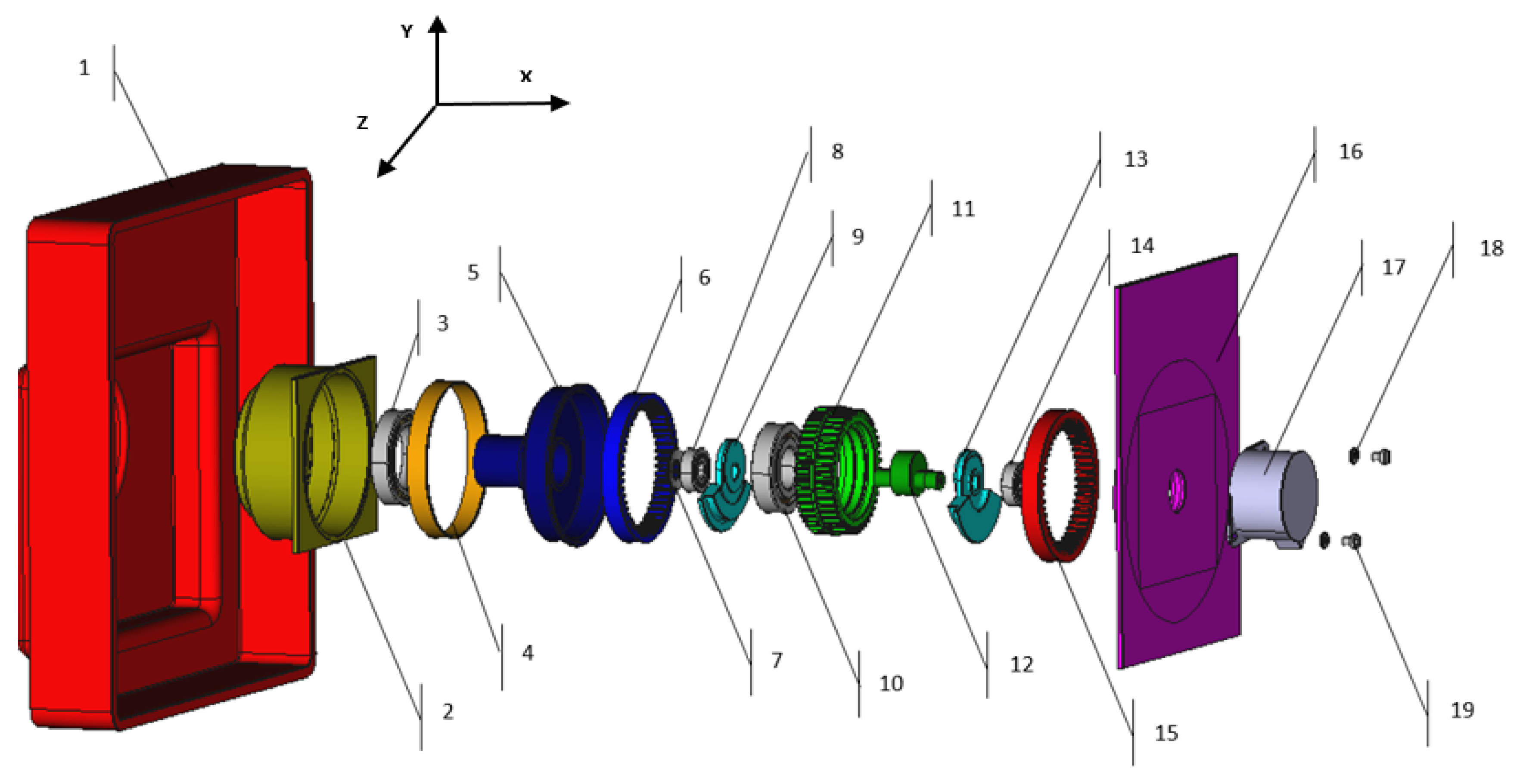
The exploded view of the speed reducer design.

Figure 8.
Analysis methodology for the choice of the appropriate assembly sequence.

Figure 9.
ASP1 response to system specifications.

Figure 10.
ASP2 response to system specifications.

Figure 11.
ASP3 response to system specifications.

Figure 12.
Process performance analysis of ASP1, ASP2 and ASP3.


Table 1.
Assemblability indicatorsc.
| Indicators | Specifications | Limit Values |
|---|---|---|
| Product performance | Number of parts (N) Cost (C) Design efficiency (De) | Defined by SE in accordance with the working group |
| Process performance | Total assembly time (TAT) Insertion ratio (IR) Handeling ratio (HR) Assemblability ratio (AR) Complexity factor (CF) | Defined by SE in accordance with the working group |
Table 2.
Speed reducer assembly nomenclature.
| Rep | Item | No |
|---|---|---|
| 1 | Customer enclosure | 1 |
| 2 | Housing bottom output interface | 1 |
| 3 | Bearing out bottom | 1 |
| 4 | PTFE film adhesive | 1 |
| 5 | Internal gear output | 1 |
| 6 | Gear inner output | 1 |
| 7 | Spring belleville | 1 |
| 8 | Bearing bottom | 1 |
| 9 | Counter weight bottom | 1 |
| 10 | Bearing compound | 1 |
| 11 | Gear compound | 1 |
| 12 | Shaft eccentric | 1 |
| 13 | Counter weight top | 1 |
| 14 | Bearing top | 1 |
| 15 | Gear inner fixed | 1 |
| 16 | Gear inner fixed | 1 |
| 17 | Motor stepper | 1 |
| 18 | Nut | 2 |
| 19 | Screw | 2 |
Table 3.
Three possible assembly sequence plans of the speed reducer.
| ASP1 | Part | 1 | 2 | 4 | 3 | 5 | 6 | 7 | 8 | 9 | 12 | 10 | 11 | 15 | 13 | 14 | 16 | 17 |
| Axis | −x | −x | −x | −x | −x | −x | −x | −x | −x | −x | −x | −x | −x | −x | −x | −x | ||
| ASP2 | Part | 16 | 17 | 14 | 13 | 12 | 9 | 8 | 7 | 15 | 10 | 11 | 6 | 5 | 4 | 3 | 2 | 1 |
| Axis | −x | +x | +x | +x | +x | +x | +x | +x | +x | +x | +x | +x | +x | +x | +x | +x | ||
| ASP3 | Part | 17 | 16 | 14 | 13 | 12 | 15 | 11 | 10 | 6 | 9 | 8 | 7 | 5 | 3 | 4 | 2 | 1 |
| Axis | +x | +x | +x | +x | +x | +x | +x | +x | +x | +x | +x | +x | +x | +x | +x | +x |
Publisher’s Note: MDPI stays neutral with regard to jurisdictional claims in published maps and institutional affiliations. |
© 2022 by the authors. Licensee MDPI, Basel, Switzerland. This article is an open access article distributed under the terms and conditions of the Creative Commons Attribution (CC BY) license (https://creativecommons.org/licenses/by/4.0/).
Share and Cite
MDPI and ACS Style
Brahmi, R.; Belhadj, I.; Hammadi, M.; Aifaoui, N.; Choley, J.-Y. CAD-MBSE Interoperability for the Checking of Design Requirements Based on Assemblability Indicators. Appl. Sci. 2022, 12, 566. https://doi.org/10.3390/app12020566
AMA Style
Brahmi R, Belhadj I, Hammadi M, Aifaoui N, Choley J-Y. CAD-MBSE Interoperability for the Checking of Design Requirements Based on Assemblability Indicators. Applied Sciences. 2022; 12(2):566. https://doi.org/10.3390/app12020566
Chicago/Turabian StyleBrahmi, Rihab, Imen Belhadj, Moncef Hammadi, Nizar Aifaoui, and Jean-Yves Choley. 2022. "CAD-MBSE Interoperability for the Checking of Design Requirements Based on Assemblability Indicators" Applied Sciences 12, no. 2: 566. https://doi.org/10.3390/app12020566
Note that from the first issue of 2016, this journal uses article numbers instead of page numbers. See further details here.