
Visual Recognition and Its Application to Robot Arm Control

Department of Communications, Navigation & Control Engineering, National Taiwan Ocean University, 2 Pei-Ning Road, Keelung 20224, Taiwan
*
Author to whom correspondence should be addressed.
Appl. Sci. 2015, 5(4), 851-880; https://doi.org/10.3390/app5040851
Submission received: 30 July 2015
/
Revised: 29 September 2015
/
Accepted: 9 October 2015
/
Published: 20 October 2015
(This article belongs to the Special Issue Selected Papers from the International Multi-Conference on Engineering and Technology Innovation 2015 (IMETI2015))
Abstract
:This paper presents an application of optical word recognition and fuzzy control to a smartphone automatic test system. The system consists of a robot arm and two webcams. After the words from the control panel that represent commands are recognized by the robot system, the robot arm performs the corresponding actions to test the smartphone. One of the webcams is utilized to capture commands on the screen of the control panel, the other to recognize the words on the screen of the tested smartphone. The method of image processing is based on the Red-Green-Blue (RGB) and Hue-Saturation-Luminance (HSL) color spaces to reduce the influence of light. Fuzzy theory is used in the robot arm’s position control. The Optical Character Recognition (OCR) technique is applied to the word recognition, and the recognition results are then checked by a dictionary process to increase the recognition accuracy. The camera which is used to recognize the tested smartphone also provides object coordinates to the fuzzy controller, then the robot arm moves to the desired positions and presses the desired buttons. The proposed control scheme allows the robot arm to perform different assigned test functions successfully.

1. Introduction
Advanced robotic technologies add convenience to human life, not only in industrial applications, but also in the fields of education and entertainment. Researchers have developed numerous types of robots to meet different demands, so that the human-robot interactions are simplified and robots can carry out more complex functions. There are many kinds of robotic systems, but the robot arm is the one most used [1]. For many factories in the industrial field, such as car assembly plants, the use of robot arms is an important tool in the manufacturing process. In order for the movement of robot arms to be controlled according to the target positions, the robot arm movement needs to be designed with respect to stability and precision. As the recognition technology has improved in a variety of ways, robots have become more human-like; hence, these robots are called humanoid robots, as they resemble humans in appearance and imitate their behavior. Robots now offer valuable assistance for humans in their everyday life.
There are now many smartphones on the market, which means that thousands of touch panels must be tested by quality assurance engineers, which can be a dull job. Therefore, we have designed a smartphone automatic test system that uses a robot arm to reduce human operating time and human resources. The mechanical arm of the traditional design generally uses fixed path planning and strategies to control the entire procedure, so that the robot can reach a specific target position and complete the task, as with industrial robot arms. Although the robot arm can finish tasks accurately, if the target position is changed, the robot arm cannot reach the new point until the whole control process has been redesigned. In this study, we applied a two-camera vision system to recognize the characters and locate the position of the targets. A video camera was utilized to capture the commands on the screen of the control panel and another camera was used to read characters and recognize the screen image of the smart phone. The proposed system identifies an object position and the control scheme calculates the relative position of the moving path through image processing and fuzzy control, and then drives the robot arm to reach the desired position. The effectiveness of the proposed control design was verified by the combination of hardware and software tests.
A number of researchers have studied the motion control of robot arms over the past decades. Furuta [2] considered the dynamic equation of a robot arm. Based on sensor signal feedback, a PID control was designed for the arm to achieve the desired position. Munasinghe [3] established a simulation system of the robot arm so that the coordinates of each joint could be computed by the simulation system; thus, the arm could be controlled to track an assigned trajectory. Koga [4] calculated the magnitude of the torque for each joint of the robot arm when it grabs an object. Using the PA-10 robot arm made by Mitsubishi Company as a platform, the paper [5] proposed the concept of a harmonic drive model to investigate the gravity and material influence on the robot arm. Moreover, the robot arm was controlled so as to track a desired trajectory and the motion error analyzed. In [6], a two-link robot arm was controlled by a fuzzy sliding mode controller, in which the parameters were adjusted by fuzzy-neural techniques.
In general, the kinematics for robot arms includes two basic problems: the forward kinematics problem and the inverse kinematics problem. Usually, forward kinematics is solved by building a D-H model [1,7], deriving the kinematics and differential kinematics formula of the robot to control the robot arm and change its position. Based on the D-H model, it is evident that the kinematics of robot manipulators are nonlinear functions and, actually, the combination of trigonometric functions. The complexity of inverse kinematics usually makes it more difficult to find solutions than with forward kinematics; therefore, researchers have developed different approaches for inverse kinematics. The robot arm system in [8] was designed to implement the elevator button-pushing behavior by using an inverse kinematics technique. Recently, some research efforts have been directed to solving the inverse kinematics problem using fuzzy logic [9,10]. For the combining of image processing with the robot arm, some papers [11,12] presented the use of a camera on the robot arm to identify the target and find its location, and then the arm can find the target successfully.
The aim of this study was to provide vision ability to the robot arm through the use of character recognition techniques, as the robot arm must be able to recognize characters on the control panel and the smartphone. Lettoumeau et al. [13] presented an approach making it possible for an autonomous mobile robot to read characters, using characters printed on a colored sheet and a neural network trained to identify characters in different conditions to take into consideration the various viewpoints possible. Qadri et al. [14] proposed an image processing technology which used the number license plate to identify the vehicle, called Automatic Number Plate Recognition (ANPR). The ANPR system robustly detects and recognizes the vehicle using the license plate under different lighting conditions, and it can be implemented at the entrance of highly restricted areas. Finally, template matching and probability classifications can be used to recognize the characters. In this study, a multi-degree-of-freedom manipulator, vision sensor, image processing and fuzzy theory were applied to the control scheme design. Through position control and image processing, the proposed control scheme proved capable of recognizing characters and driving the robot arm to press the desired button of the tested smartphone. Besides the Introduction section, this paper is organized as follows. Section 2 gives the experimental setup and the kinematic model of the robot that are used in this study. Section 3 describes the methods of image processing for characters recognition. Section 4 proposes the control sequence and a fuzzy controller to the robot arm control. Section 5 presents two experiments to confirm the proposed control scheme. Section 6 concludes this research.
2. System Setup
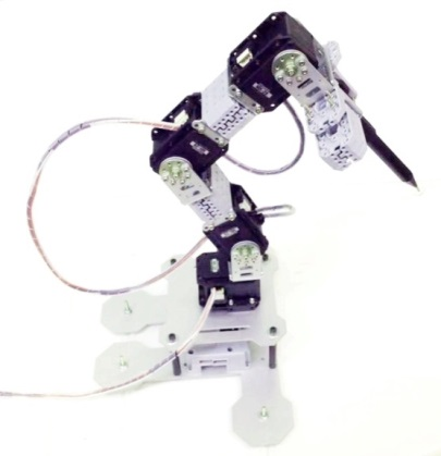
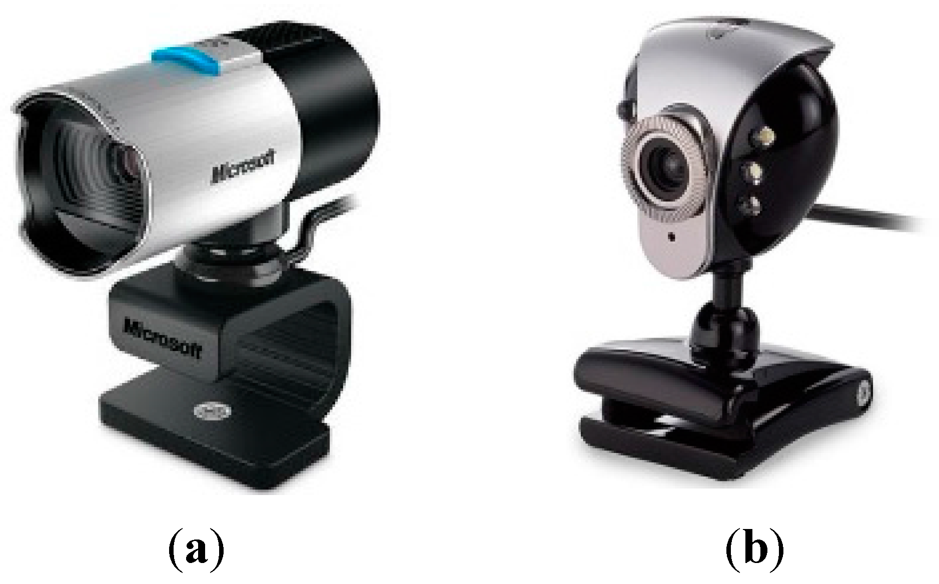
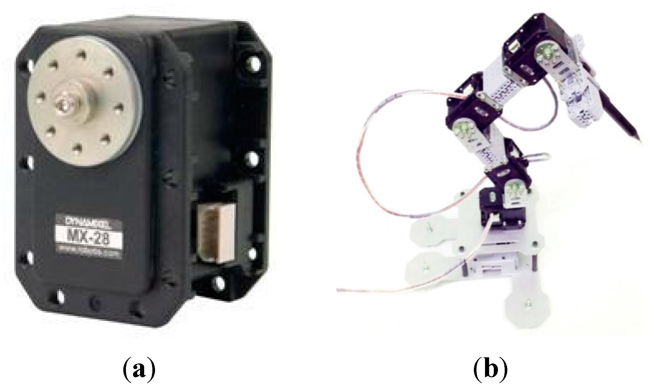
In this study, an embedded computer was used as the main controller. A network camera, Microsoft LifeCam Studio 1080P Full-HD (Microsoft Taiwan Corporation, Taipei, Taiwan), and an E-books W6 PC Webcam (Chung Ching Technical Co., Taichung, Taiwan) were used for the image processing, as shown in Figure 1. The Dynamixel MX-28 servo motor produced by Robotis Company (Seoul, Korea) was the main motive force of the robot arm, as shown in Figure 2.
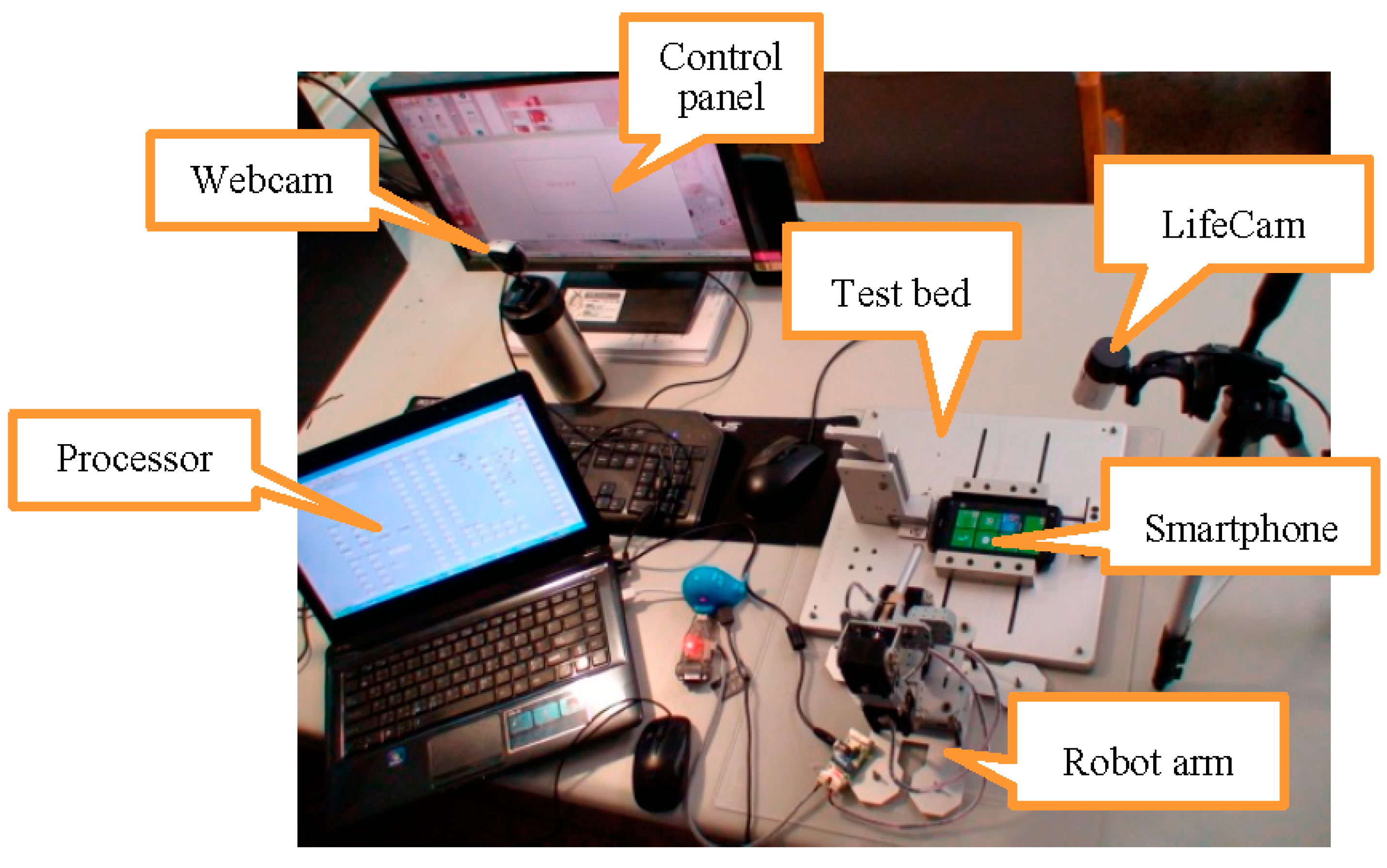
The motor weight was 72 g, dimensions of 35.6 × 50.6 × 35.5 (mm), resolution of 0.088°, running degree of 0°–360°, gear reduction ratio of 193:1, stall torque of 24 kgf-cm (at 12 V, 1.5 A) and a no-load speed of 54 rpm (at 12 V). Figure 3 shows the experimental setup with a smartphone on the test board.
Figure 1.
(a) Microsoft LifeCam Studio 1080P Full-HD and (b) E-books W6 PC Webcam.

Figure 2.
(a) Dynamixel MX-28 servo motor and (b) robot arm.

Figure 3.
Experimental setup includes the control panel (PC screen), main processor (notebook), Microsoft LifeCam, E-books Webcam, robot arm, tested smartphone, and test bed.
Figure 3.
Experimental setup includes the control panel (PC screen), main processor (notebook), Microsoft LifeCam, E-books Webcam, robot arm, tested smartphone, and test bed.

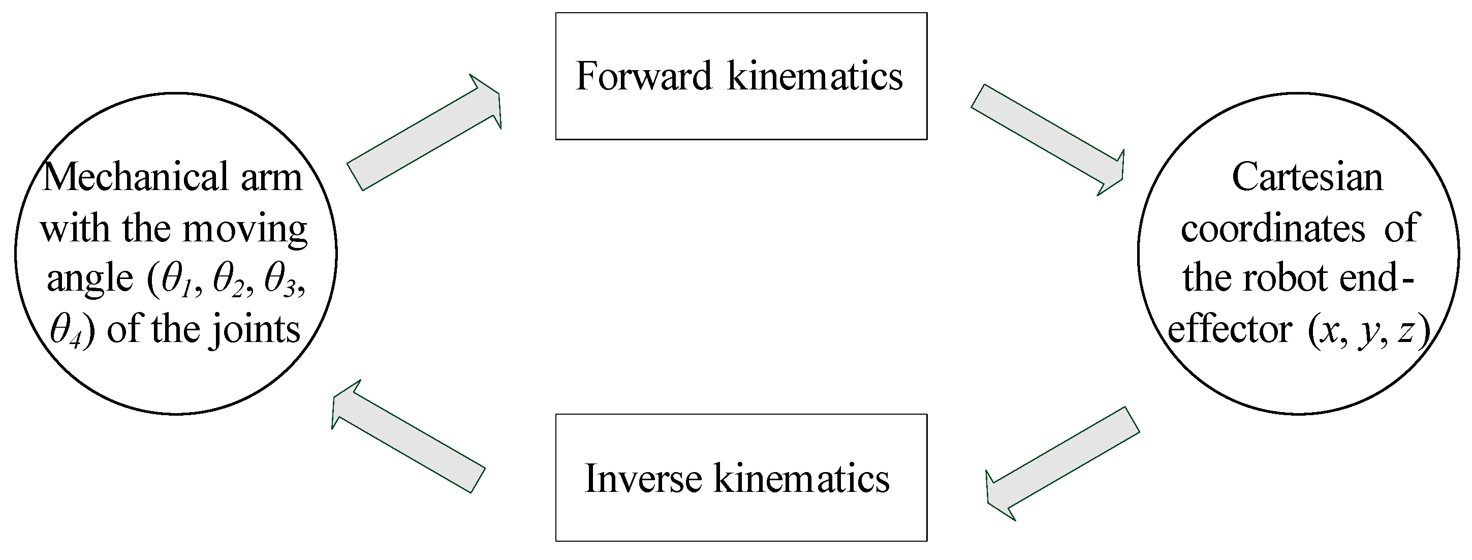
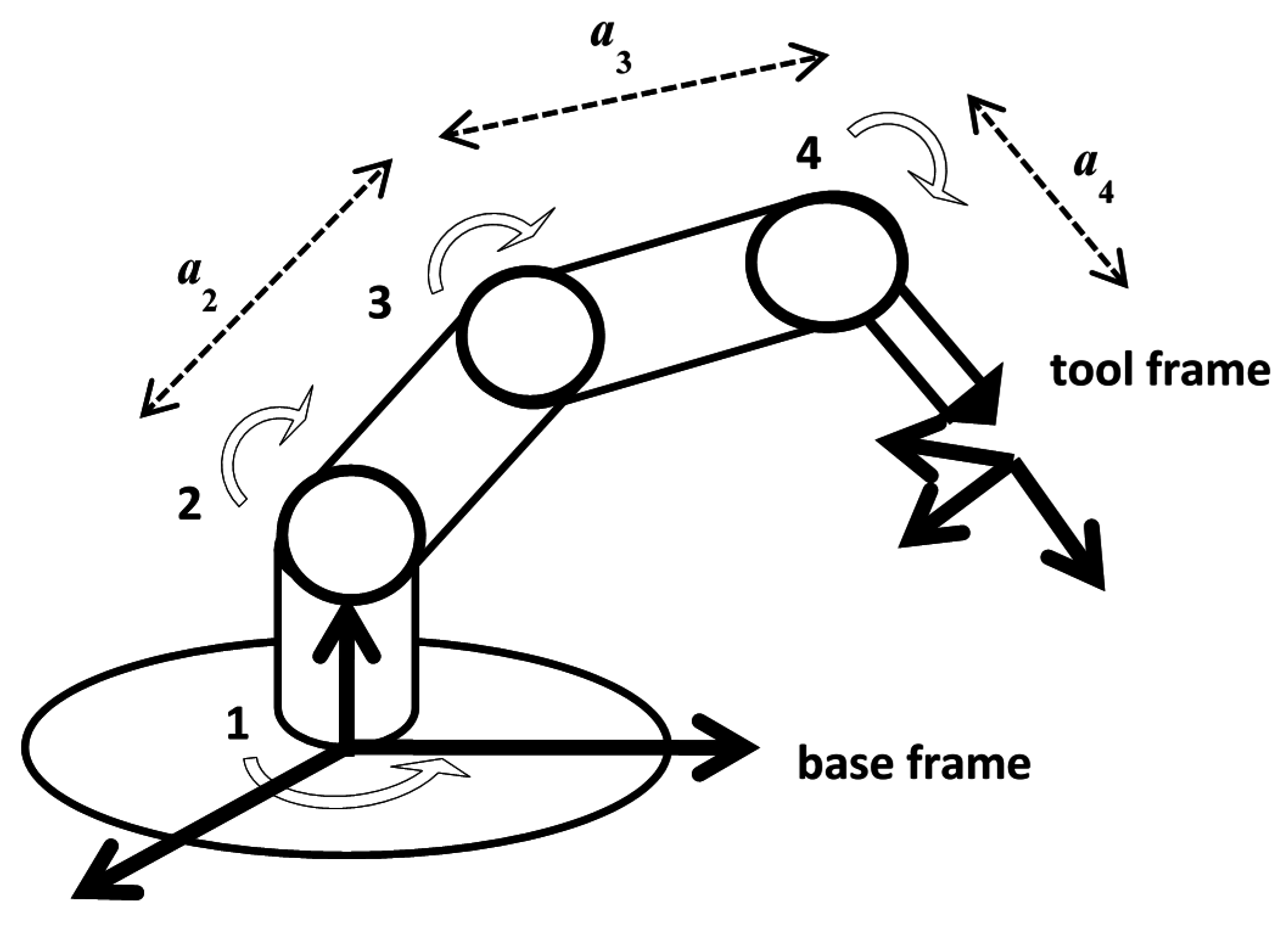
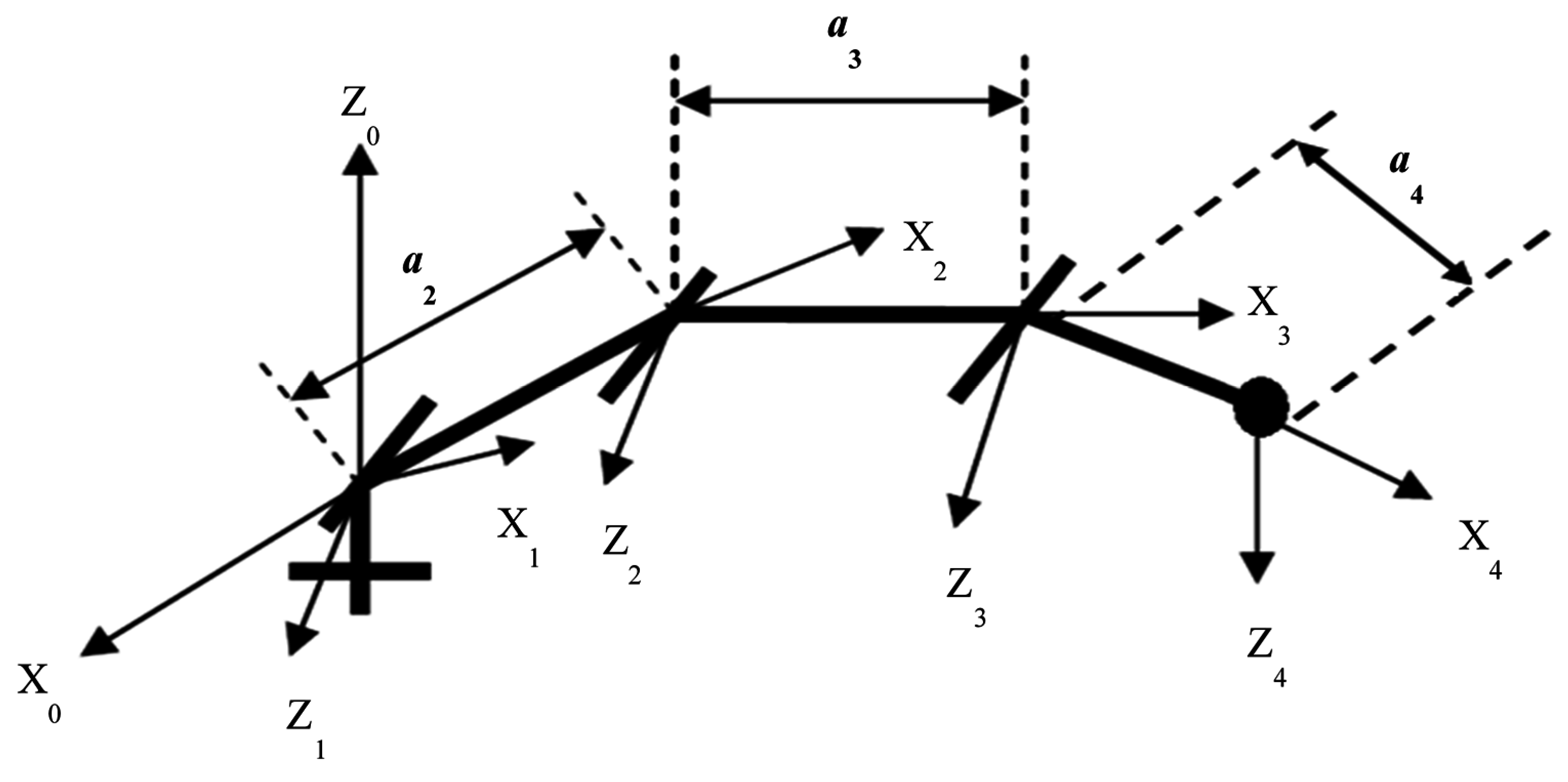
Kinematics [15] mainly defines the conversion in the space of Cartesian coordinates (x, y, z) and the mechanical arm with the moving angle (θ1, θ2, θ3, θ4) of the joints. Forward kinematics can be considered as a mapping from the joint space to the operational space with the coordinates of the robot end-effector. Inverse kinematics is a mapping from the operational space with the coordinates of the robot end-effector to the joint space, so it can be considered as the inverse of forward kinematics. Figure 4 explains the relationship of forward kinematics and inverse kinematics. The presented kinematic model of the arm has four degrees of freedom. The model of the robotic arm is presented in Figure 5. There are four parameters that fully describe the kinematic relationship between every neighboring joint and link in a manipulator. These four parameters are:
- Two neighboring joint relations: the link length ai and the link twist angle αi.
- Two neighboring link relations: the link offset di and the joint angle θi.
Figure 4.
Relationship of forward kinematics and inverse kinematics.

Figure 5.
Kinematic model of robotic arm with four degrees of freedom.

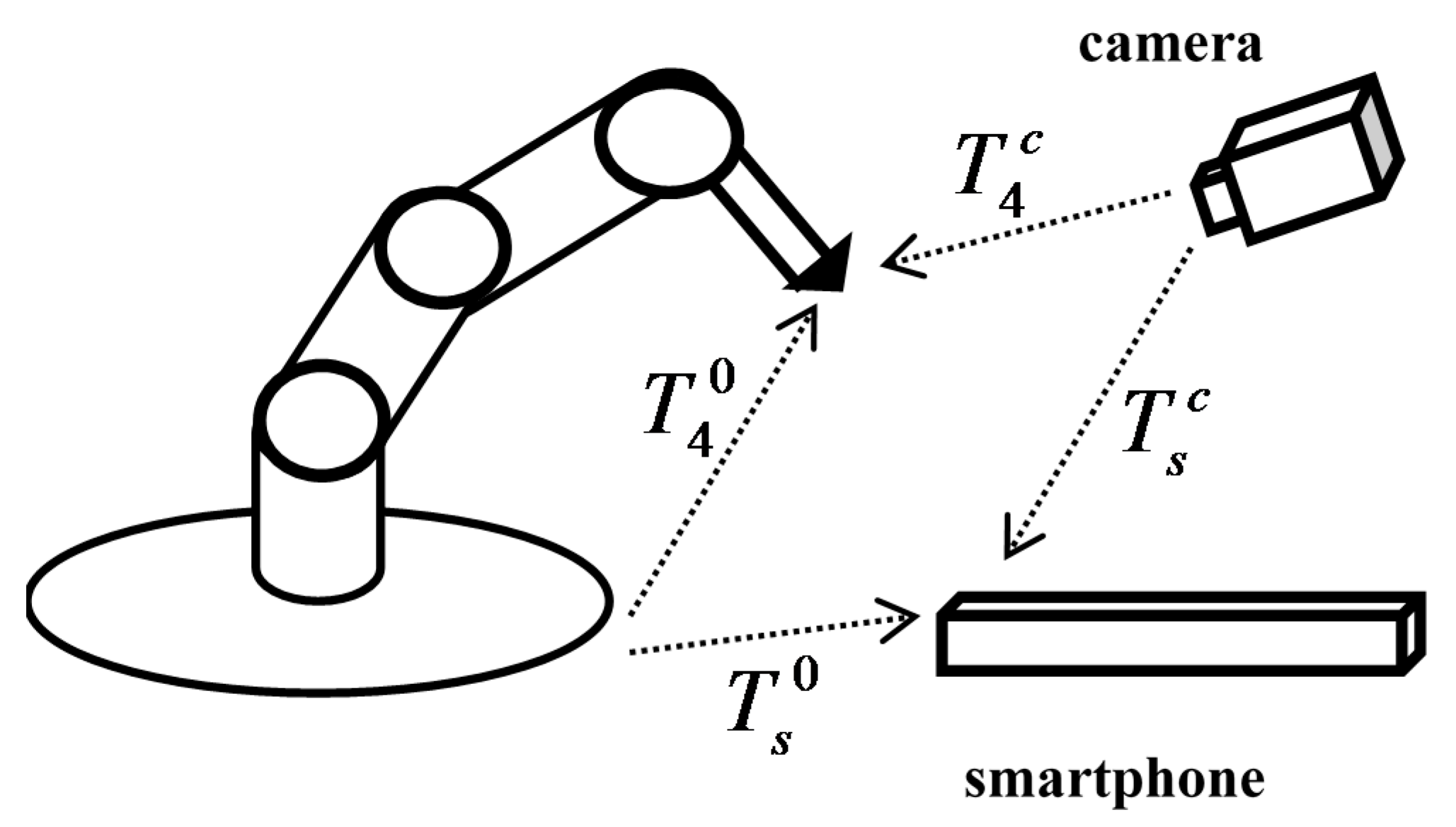
Because the views of the camera and robot arm are different, a coordinate transformation process is needed. The coordinate transformation relationship is shown in Figure 6, where T40 is the coordinate transformation relationship of the base frame and end-effector, T4c is the coordinate transformation relationship for the camera and end-effector, Ts0 is the coordinate transformation relationship of the base frame and smartphone and Tsc is the coordinate transformation relationship of the camera and smartphone. We needed to collect more than three data, and then use the least squares method to obtain the transformation matrix. Because the z-axis coordinates are the same, we only needed to use x coordinates and y coordinates, where xi and yi are the pattern matching coordinates, and xr and yr are the robot end-effector coordinates.
where r11, r12, r21 and r22 are rotation, and r13 and r23 are translation. From Equation (1), we have:
From Equations (2) and (3), we have:
From Equations (4) and (5), we have:
From Equations (6) and (7), we use the least squares method to obtain ψ1 and ψ2:
Figure 6.
Coordinate transformation relationship.

3. Pattern Recognition
The premier task in this study was to control the robot arm so it could reach the target position successfully. An image of a target is affected by the light source. This section presents the method that transforms the RGB (Red, Green and Blue) color space to HSL (Hue, Saturation and Lightness) color space, thereby significantly reducing the impact of light. Furthermore, pattern matching and character recognition are also given, both of which used NI Vision Builder for Automated Inspection (VBAI) to achieve the specified functions [16]. VBAI allows one to easily configure and benchmark a sequence of visual inspection steps, as well as deploy the visual inspection system for automated inspection. The proposed robot system used these methods to perform the position control.
3.1. Image Processing
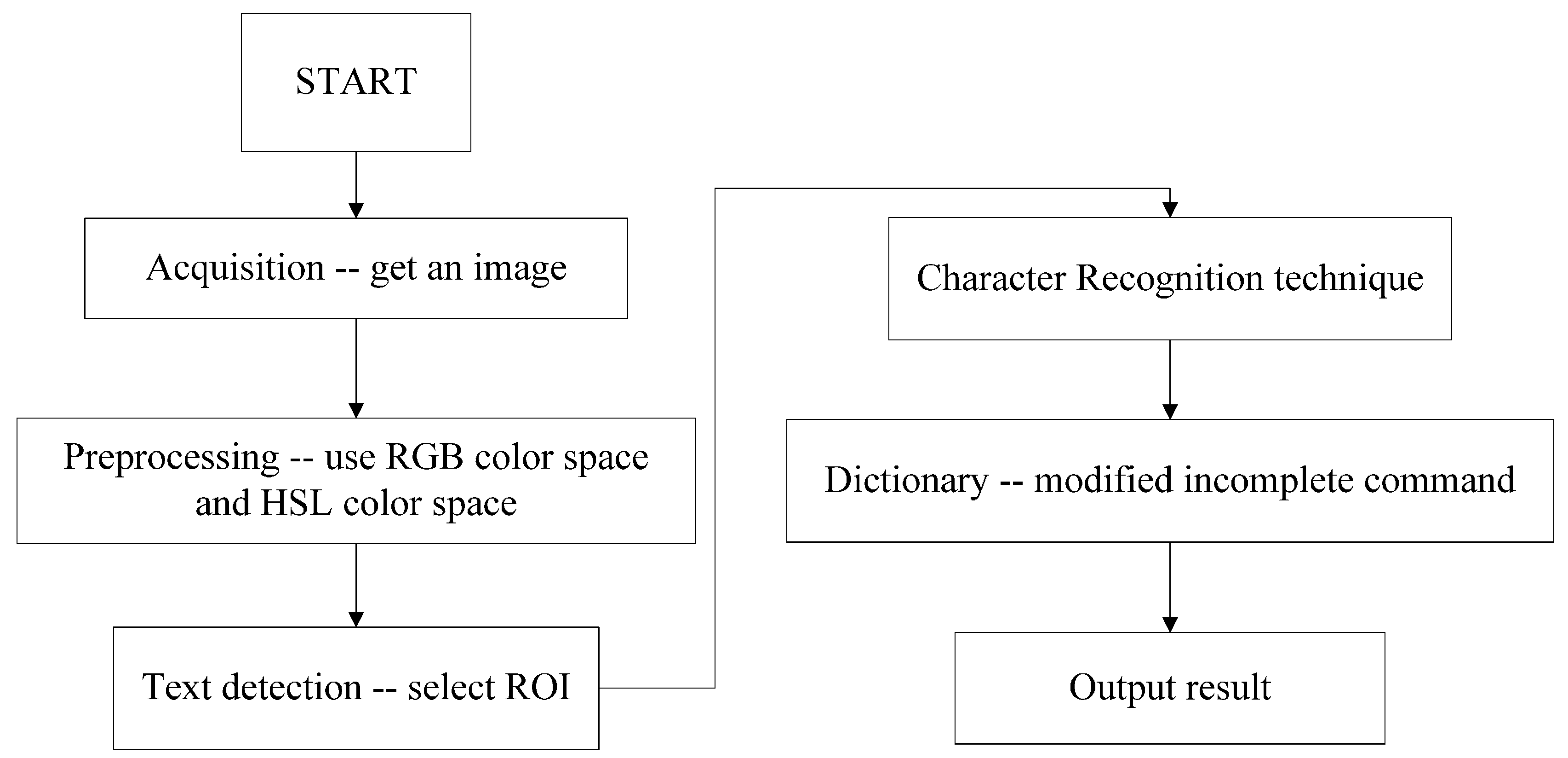
With the images obtained by two webcams, the Image Processing Module, as shown in Figure 7, must recognize the words and the symbols on the PC screen or the smartphone. This process is done in three steps: image preprocessing, image recognition and dictionary processing.
Figure 7.
Image recognition process.

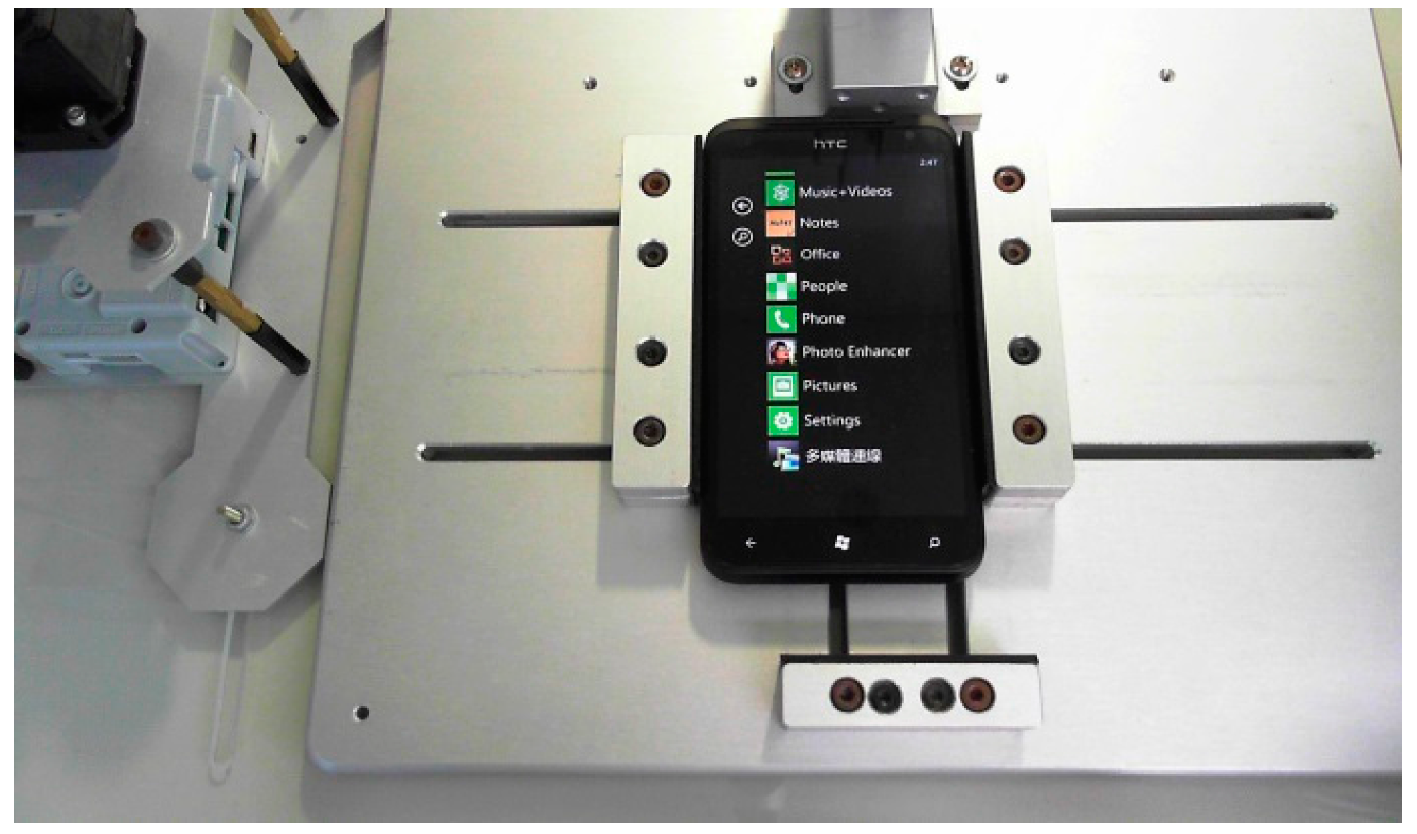
Since the RGB color mode is easily affected by any light change in the environment, the transformation from RGB to HSL models was needed, as the HSL model is more robust to light changes in the environment than the RGB model. The conversion method is given as follows:
where . The RGB image of the testing environment was taken from the webcam, as shown in Figure 8. The images to be converted from RGB color space to HSL color space are shown in Figure 9, Figure 10 and Figure 11. The testing environment was in a colorful space, and it was not easy to get rid of environment noise from the object. Figure 11 shows the converting of the color from the RGB image to L color space. This study used the L color space as the basis of the image operator.
Figure 8.
RGB image.

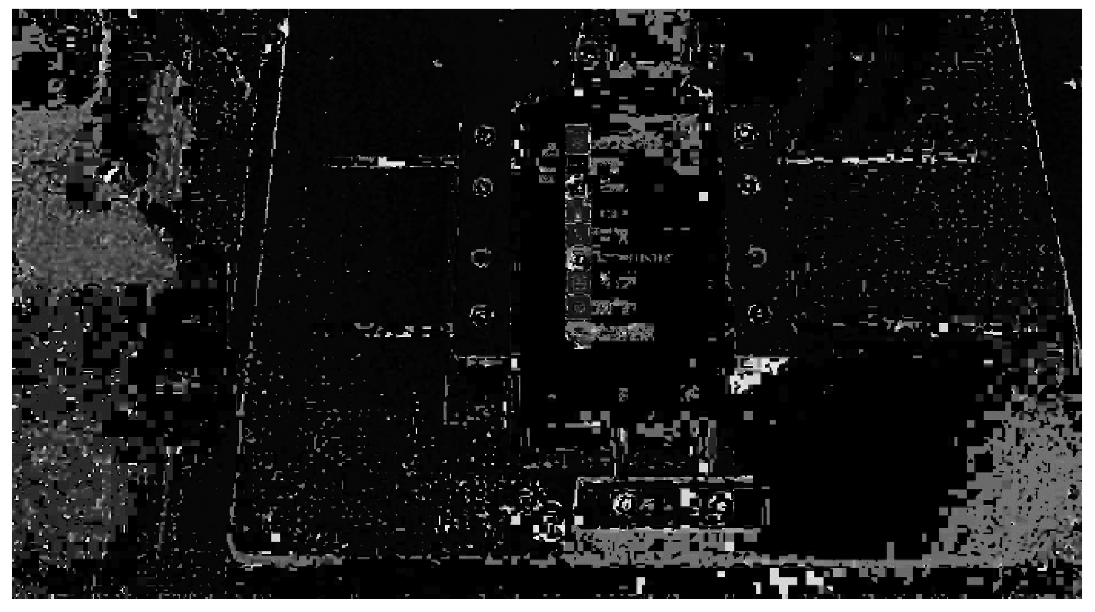
Figure 9.
Using the H color space as the basis of the image operator.

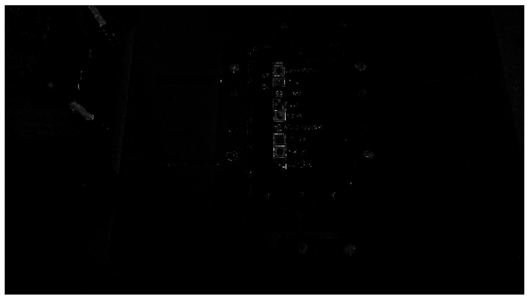
Figure 10.
Using the S color space as the basis of the image operator.

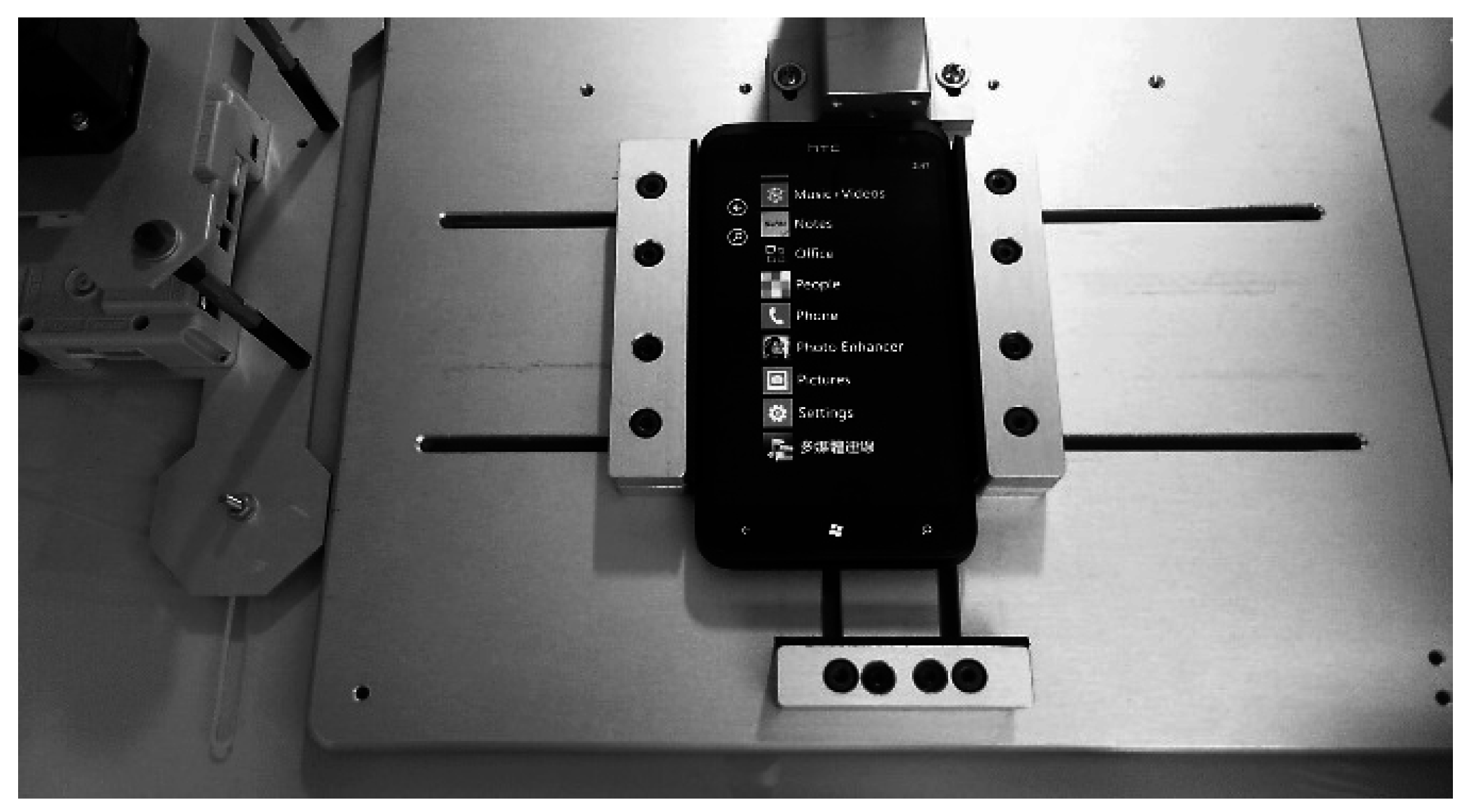
Figure 11.
Using the L color space as the basis of the image operator.

3.2. Character Recognition
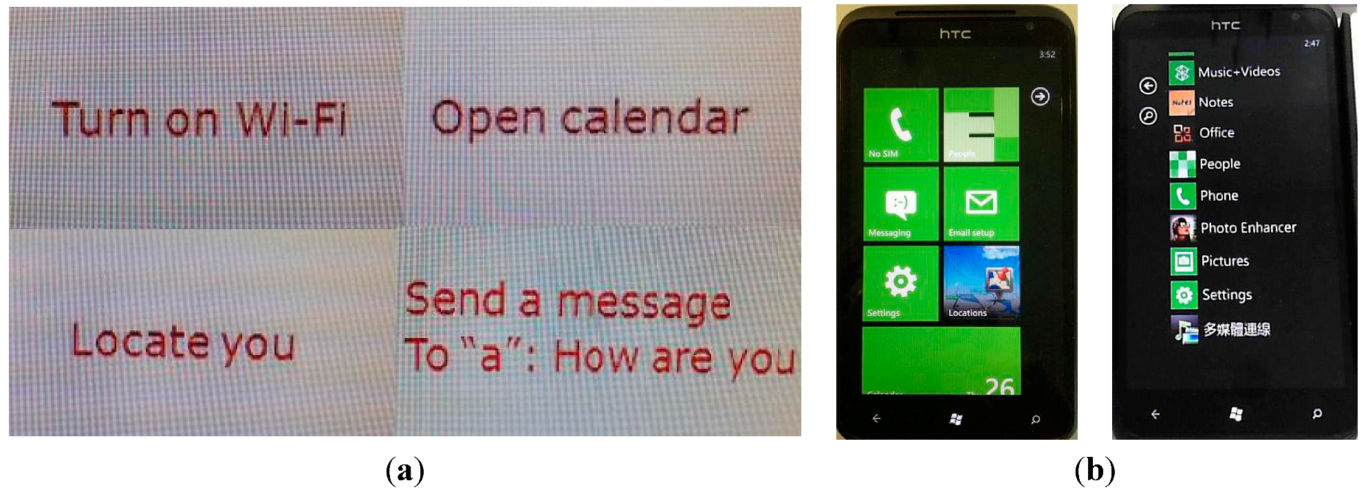
In this study, the recognition technique had two parts: pattern matching and character recognition. The PC screen can only show the commands, which are made up of different characters; the smartphone can show not only characters, but also various patterns. Examples are shown in Figure 12. We first discuss pattern matching and then character recognition.
Figure 12.
(a) Characters on the PC screen and (b) patterns and characters on the smartphone.

3.2.1. Match Pattern
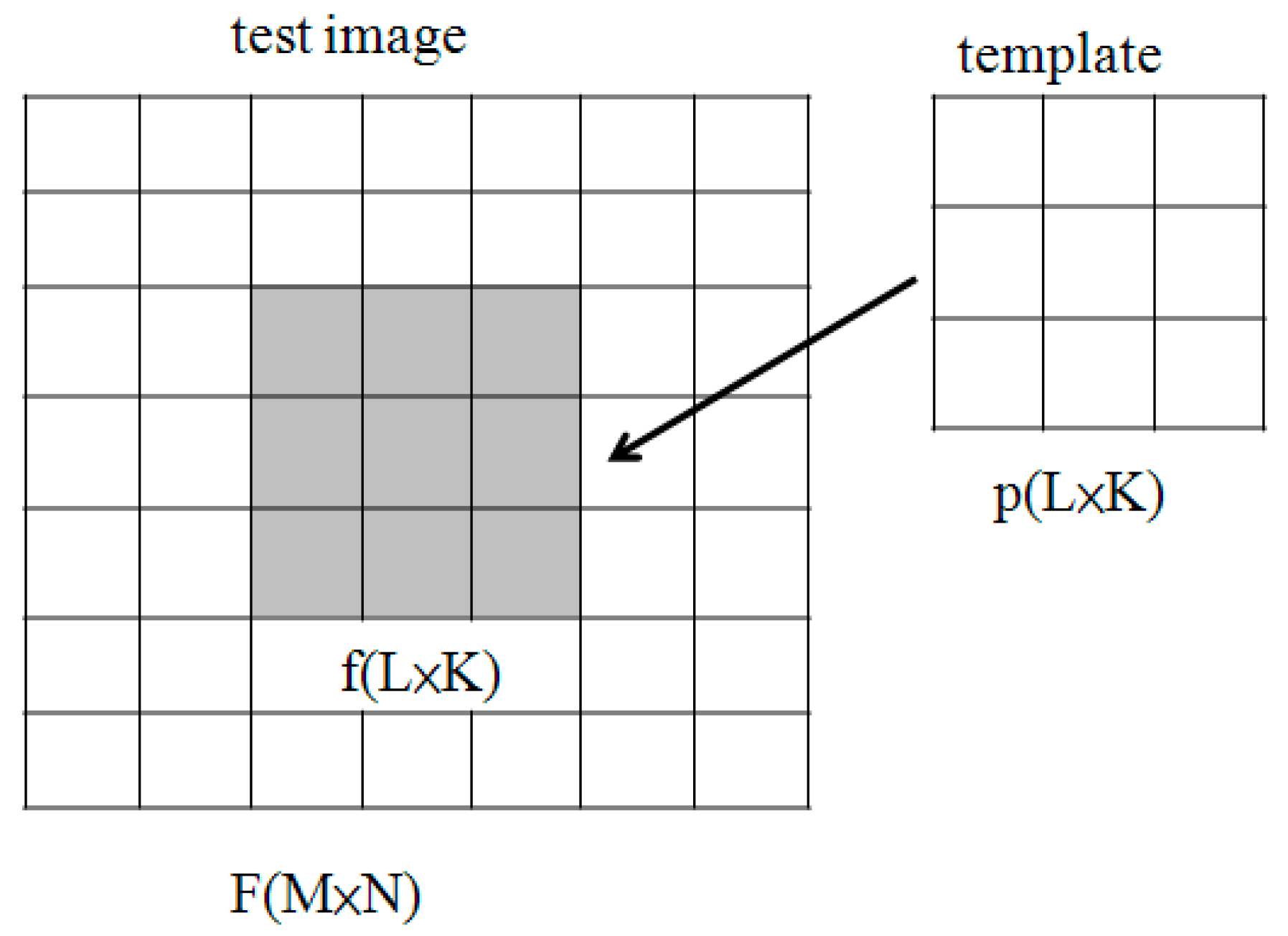
We used the Match Pattern to quickly locate known references in the image. Even the location, orientation, lighting and temperature change will not be affected. We can create a sample model of the object that we want to search, look for this sample and then calculate the similarity of each image. The model is called a template and should be an ideal representation of the pattern or object. If the similarity measure is large enough, we can assume that the object is present. The similarity measure is based on the Euclidean distance, and the cross-correlation function is computed from the similarity measure. The similarity measure based on the Euclidean distance method [17] is described below. I(x,y) is the common measure employed when comparing the similarity of two images (e.g., the template p(x,y) and the test image f(x,y)). It is the metric based on the standard Euclidean distance between two sectors, as shown in Figure 13.
![Applsci 05 00851 g013]()
Figure 13.
Match pattern.

Normalized cross-correlation (NCC) is a process used for finding incidences of a pattern or object within an image. The NCC product concept, may be scaled so that it lies in the range of 0 to 1. When R is equal to 1, it represents that p(x,y) is equal to f(x,y).
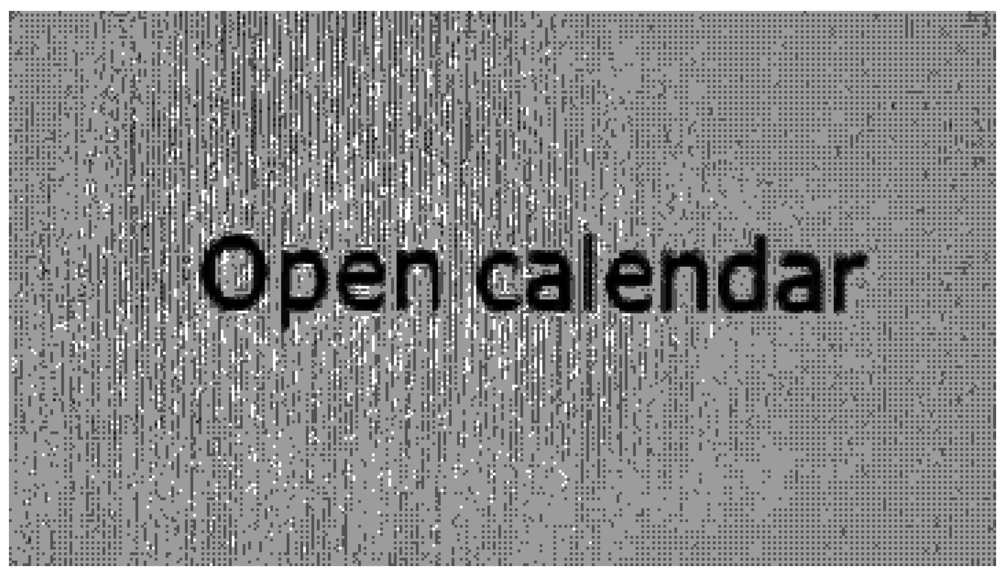
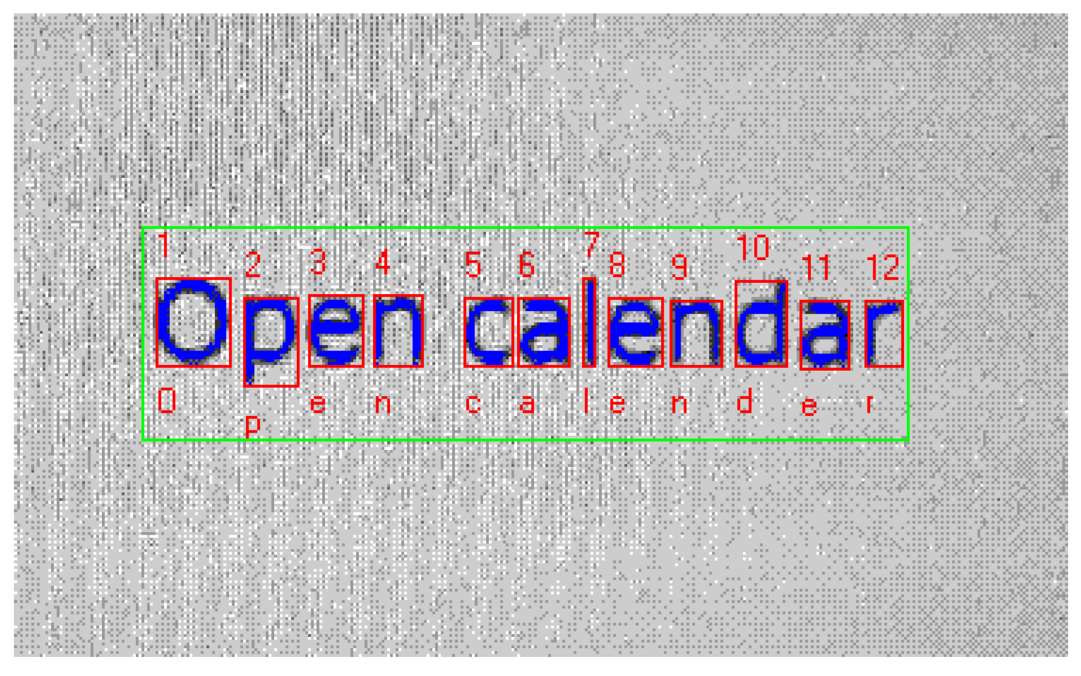
As shown in Figure 14, when the image is being preprocessed, black areas are extracted using segmentation methods [13,18]. The process works by looking pixel by pixel (from top to bottom and left to right). If the pixel and some of its eight neighbors are black, areas of black pixel connected with each other are then delimited by rectangular bounding boxes. Each box is characterized by the positions of all pixels forming the region, the area of the region and the upper left and lower right coordinates of the bounding box. Once the black areas are identified, they are sent to VBAI for recognition; the recognition result will appear below the characters, as shown in Figure 15.
Figure 14.
Preprocessed image.

Figure 15.
Recognition result.

3.2.2. Vision Builder for Automated Inspection
Machine vision applications require a combination of hardware and software to ensure success. While choosing the right hardware is important, the actual visual inspection software forms the core of any machine vision system. National Instruments has introduced configurable machine vision software with the NI Vision Builder for Automated Inspection (VBAI). VBAI allows one to easily configure and benchmark a sequence of visual inspection steps, as well as deploy the visual inspection system for automated inspection [19,20]. Webcams are programmed to recognize valuable characters continuously, and a feature is chosen such that it is always in the camera field of view despite the different locations in which the desired buttons may appear from image to image. We need to set a coordinate system relative to a significant and original feature of the desired buttons.
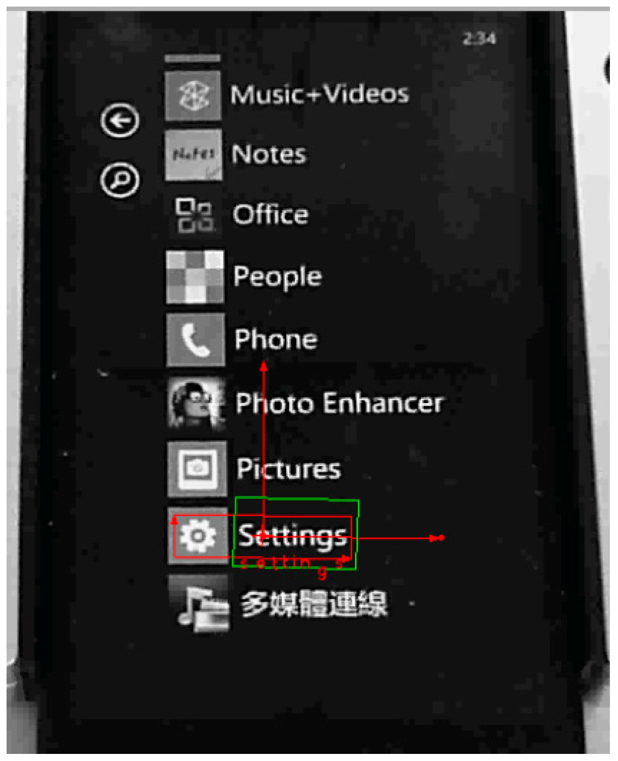
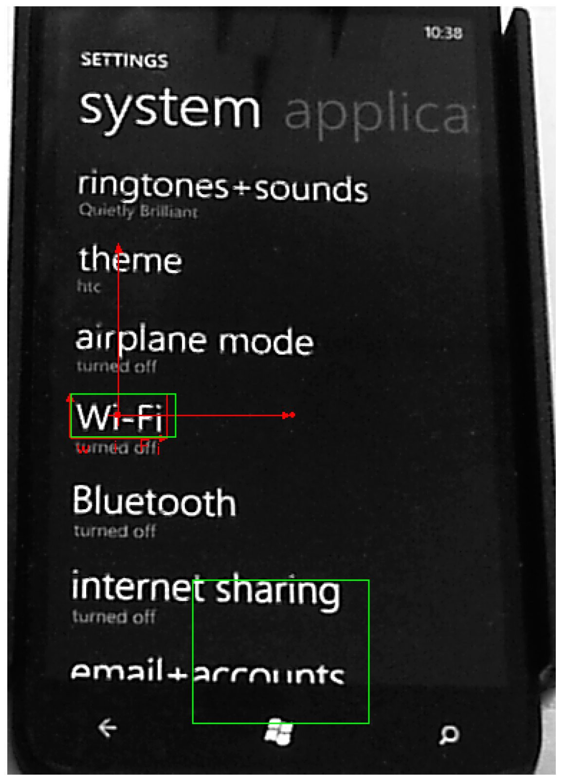
To configure the Match Pattern step and Read Text step, a region of interest (ROI) is drawn around the area of the image. This region becomes the pattern matching template. Then, the characters of the chosen template are identified. The VBAI looks for and locates the specified template inside the ROI in the image. The location of the matched pattern is overlaid on the inspection image with a red rectangle; the recognition result is shown under the template in red, as shown in Figure 16 and Figure 17.
Figure 16.
Recognition result with red characters: “Settings”.

Figure 17.
Recognition result with red characters: “Wi-Fi”.

3.2.3. Check the Pressed Button
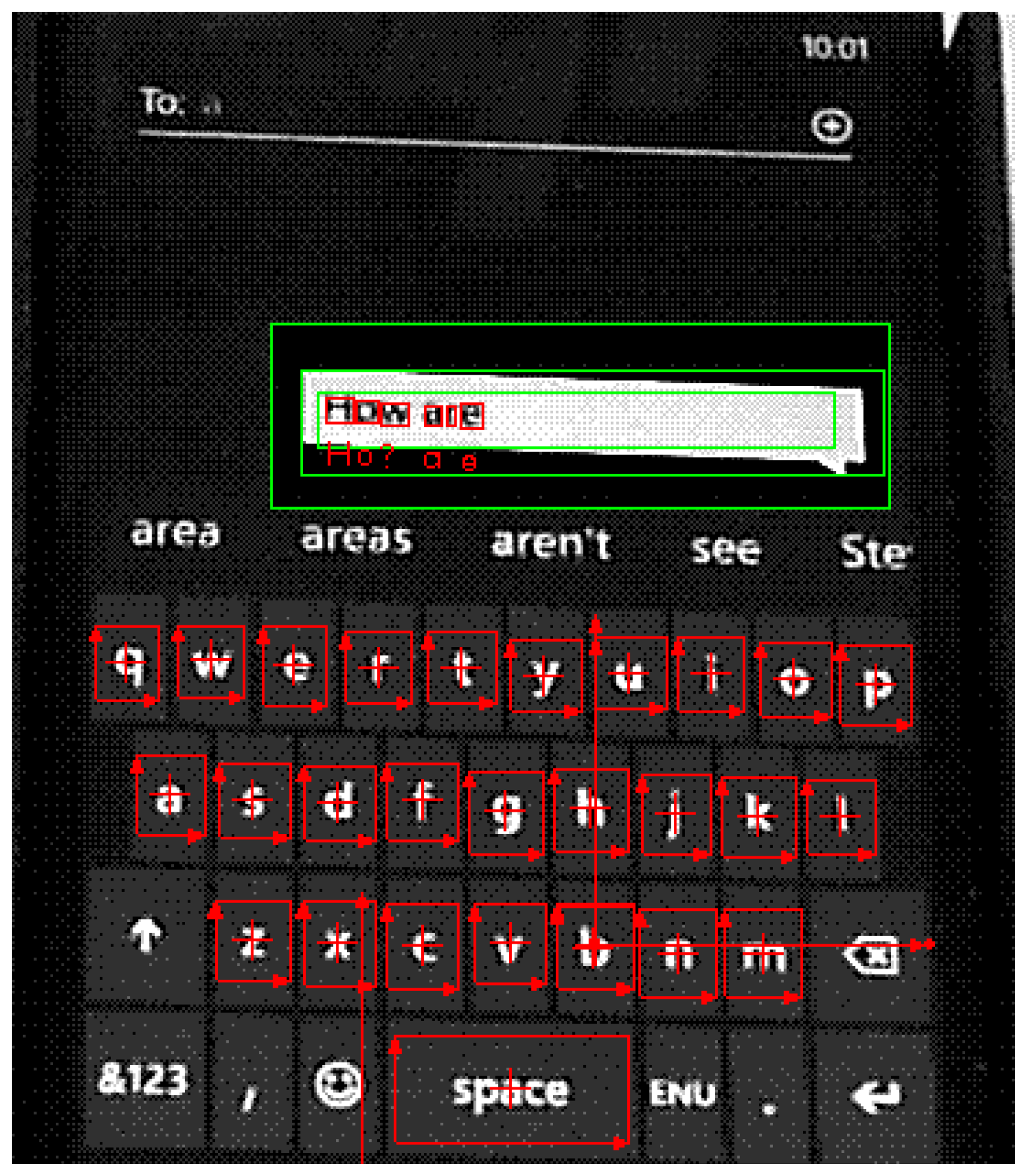
Additionally, the robot arm also has the ability to know whether or not it pressed the correct button. We used both the character recognition and X-coordinate accumulation methods to check the desired pressed button. Figure 18 shows the checking of the pressed buttons; the red rectangles in the white block represent how many words are pressed; the words under the white block are the recognition result.
Figure 18.
Check the pressed buttons.

3.2.4. Modified by Dictionary
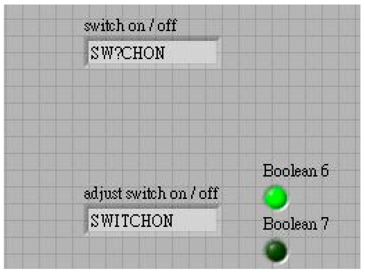
Recognition accuracy is not only affected by the brightness and light of the environment, but also by the position and angle of the webcam. The modified method was implemented using MATLAB (MathWorks, Natick, MA, USA). If word recognition is wrong, the model can correct the spelling automatically, thereby increasing the accuracy, as shown in Figure 19 and Figure 20. In this study, recognition accuracy was 92.4% for images taken from the webcam and 99% for the dictionary process.
Figure 19.
Original recognition result (missing letters: “I” and “T”).

Figure 20.
Corrected by a dictionary process.

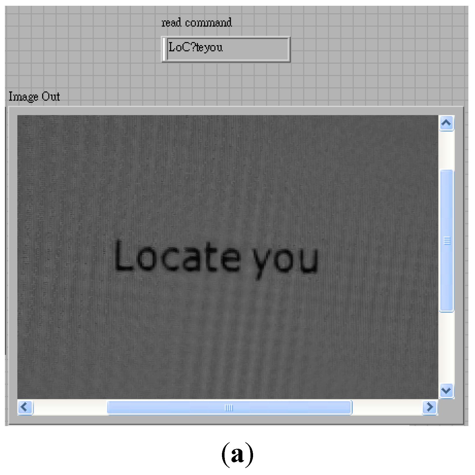
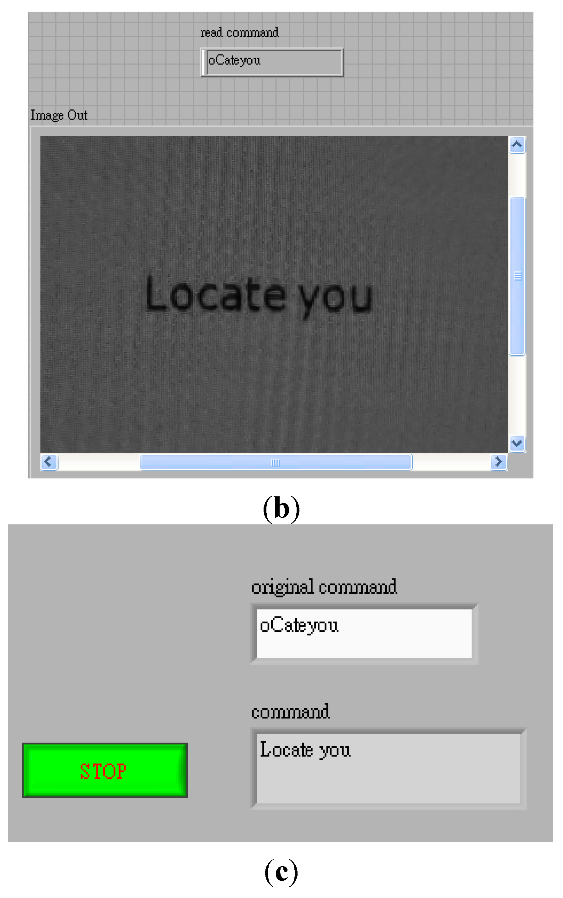
In the dictionary process, we stored a data box to meet different incomplete combinations of words. For image recognition, it was impossible to be 100% accurate every time using the camera, because of the light source, screen frequency, angle of webcam, etc., all of which can reduce the recognition rate. Figure 21a–c show the other recognition result. We found that even with the same command, different results could be obtained. The corrected process has the ability to fix such problems.
Figure 21.
Different conditions corrected by the dictionary process. (a) One of the original commands: Locate you (the third letter “c” is recognized as a capital and the letter “a” is missing); (b) The other case of the original command: Locate you (missing the first letter, L); (c) Corrected by a dictionary process.


4. Control Scheme
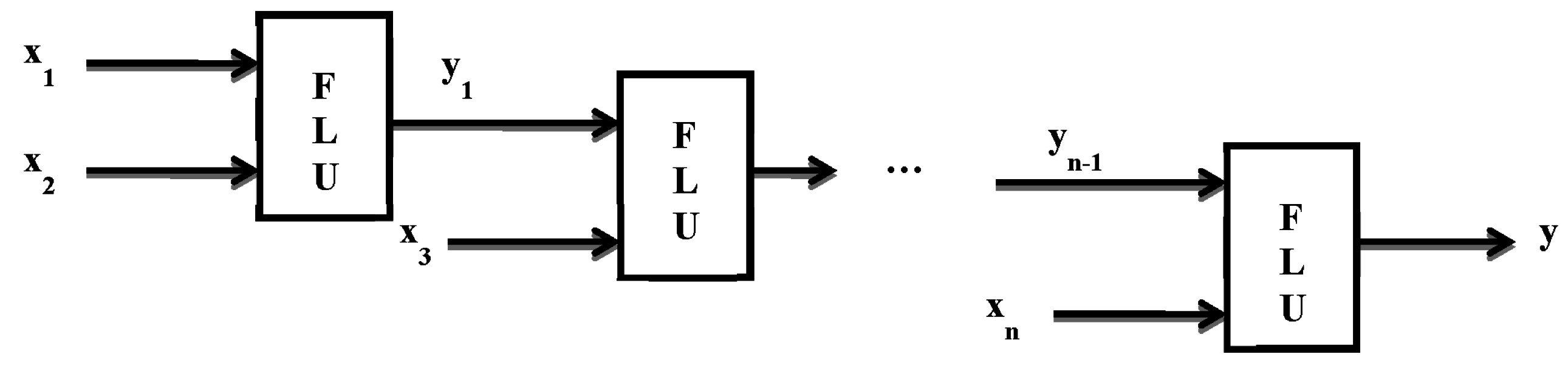
A robotic manipulator modeled with link structural flexibility during execution of a task requires the end-effector to contact the smartphone. It uses the information of the target position obtained as per the previous section. Using this methodology, position control of the end point is possible when the end effector moves to the desired position. The number of fuzzy rules grows exponentially with the number of input variables. To overcome the problem, the idea of using a hierarchical structure in the design of a fuzzy system was reported by Raju and Zhou [21], where the input variables were put into a collection of low-dimensional fuzzy logic units (FLUs) and the outputs of the FLUs used as the input variables for the FLUs in the next layer, as shown in Figure 22. According to their findings, the number of fuzzy rules employed in the hierarchical fuzzy system (HFS) is proportional to the number of input variables. A hierarchical fuzzy controller and a conventional fuzzy controller have different input and output architectures, and the difference affects the number of fuzzy rule-based structures. Using hierarchical fuzzy theory in the controller design can effectively reduce the establishment of fuzzy rules. In Figure 22, xi are the inputs and yi are the outputs of the fuzzy logic controllers.
Figure 22.
Typical structure of hierarchical fuzzy system.

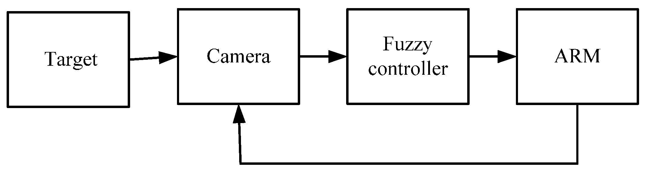
Figure 23 shows the position control scheme with the fuzzy controller: the target coordinate obtained from the camera is sent to the fuzzy controller to find four angles for each joint to make the robot arm move. The entire position control process is shown in Figure 24.
Figure 23.
Position control scheme with fuzzy controller.

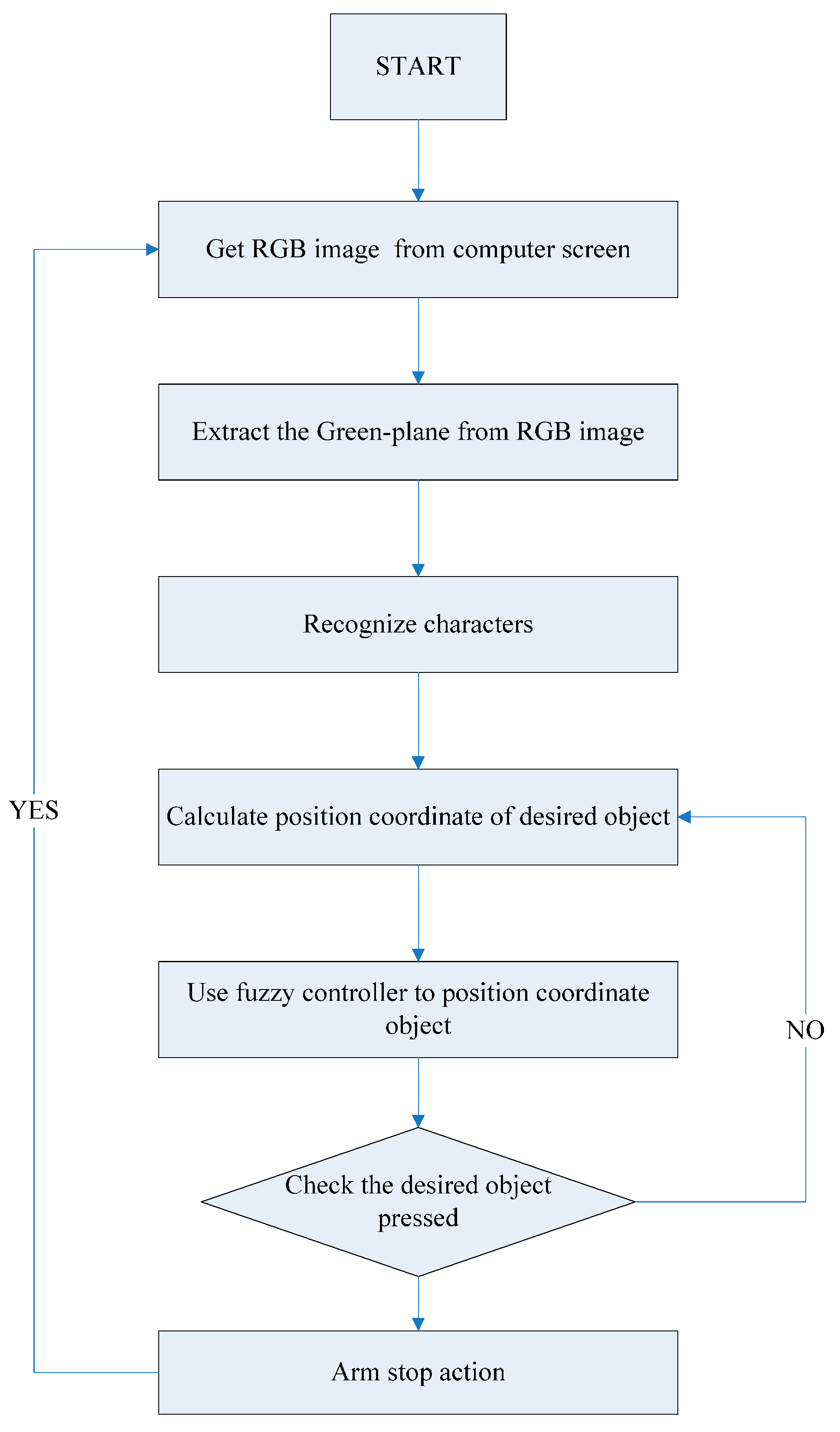
Figure 24.
Flow chart of the control sequence.

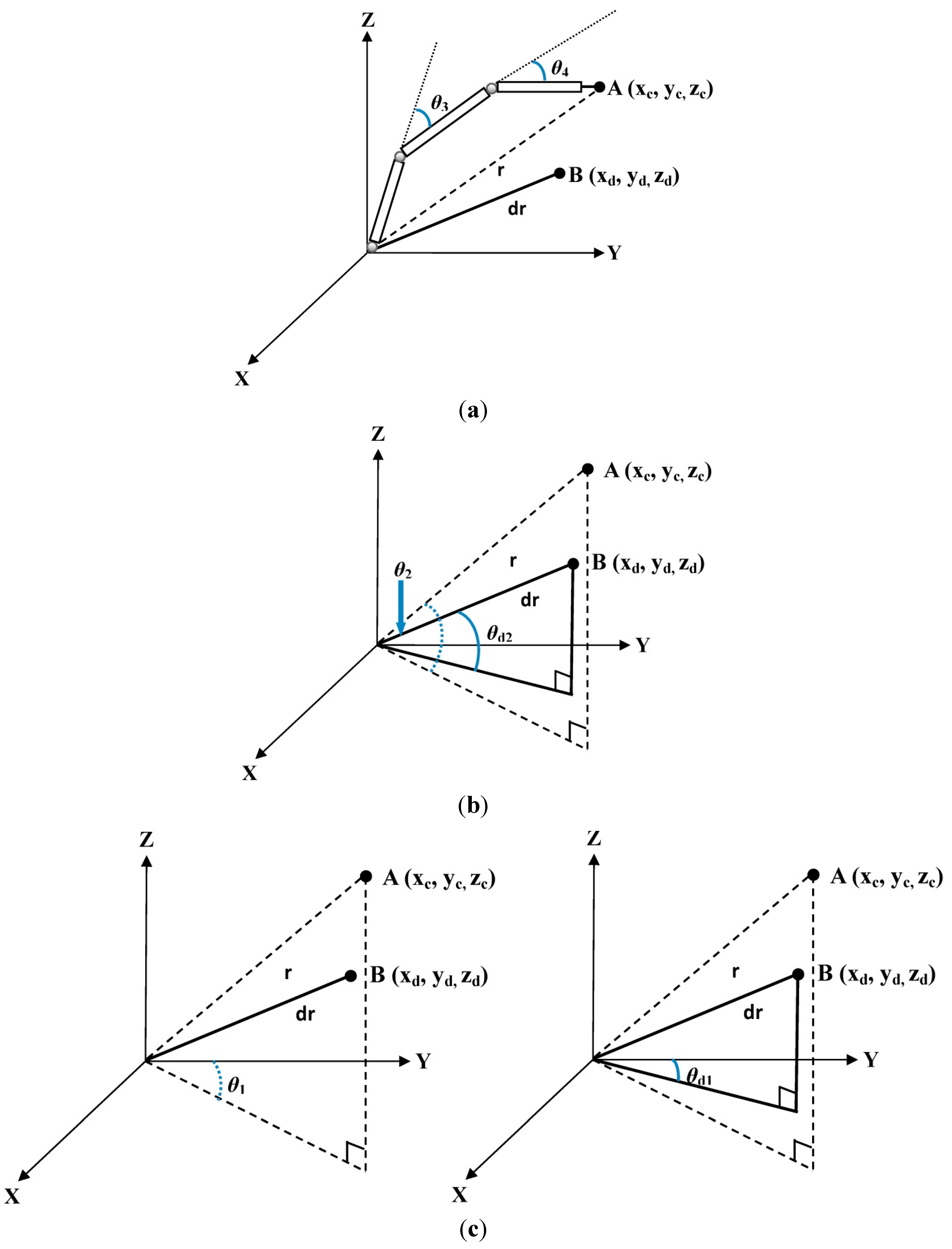
From Figure 25a–c, θ3 and θ4 particularly determine the length of r; Point A is the current coordinate of the arm’s end-effector; and point B is the desired target. When r is equal to rd; θ2 is equal to θd2; and θ1 is equal to θd1, and represents a successful move from point A to the expected point B (xd, yd, zd).
Figure 25.
Relationship of the robot arm’s joints. (a) Joints 3 and 4; (b) Joint 2; (c) Joint 1.

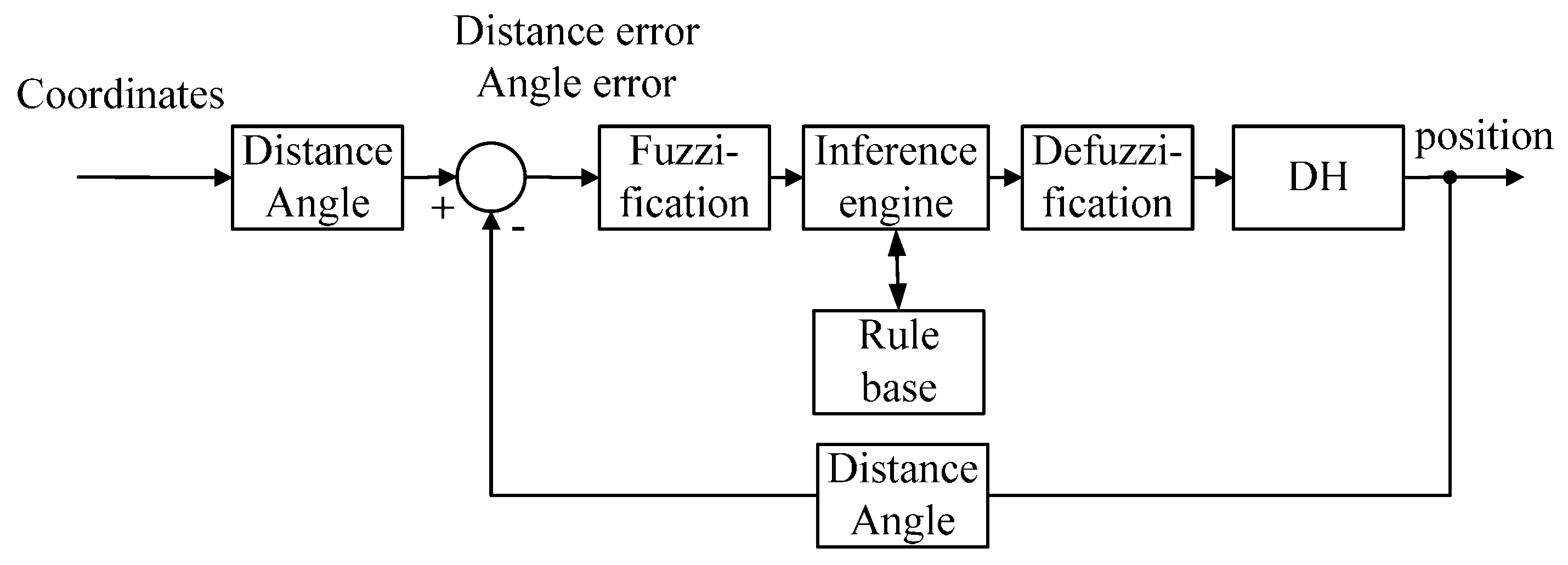
Fuzzy theory was used in the position control for the four servo motors, which did not require a complex mathematical model of the robot arm. Computations were in the order of θ3 → θ4 → θ2 → θ1. The use of the hierarchical fuzzy system effectively reduces the number of fuzzy inputs and outputs, layer by layer, with each layer having only one input and one output. Fuzzy rules are given in Appendix B. The fuzzy control scheme is shown in Figure 26.
Figure 26.
Fuzzy control scheme.

Table 1 shows the position control of one test point using three rules and five rules. We can see that the error values for each joint are less than 1°, as shown in Table 2. The error is within the preset threshold, so the robot arm still moves to the right positions.

| CoordinatesValues | x (mm) | y (mm) | z (mm) |
|---|---|---|---|
| Values | |||
| Expected Value | 173 | −101 | 25 |
| Actual value with 5 rules | 173.272 | −100.986 | 25.0894 |
| Actual value with 3 rules | 173.076 | −100.872 | 25.1421 |
| Angles | θ1 (deg) | θ2 (deg) | θ3 (deg) | θ4 (deg) |
|---|---|---|---|---|
| Values | ||||
| Error value | 0° | 0.264° | 0.44° | 0.264° |
5. Experimental Results
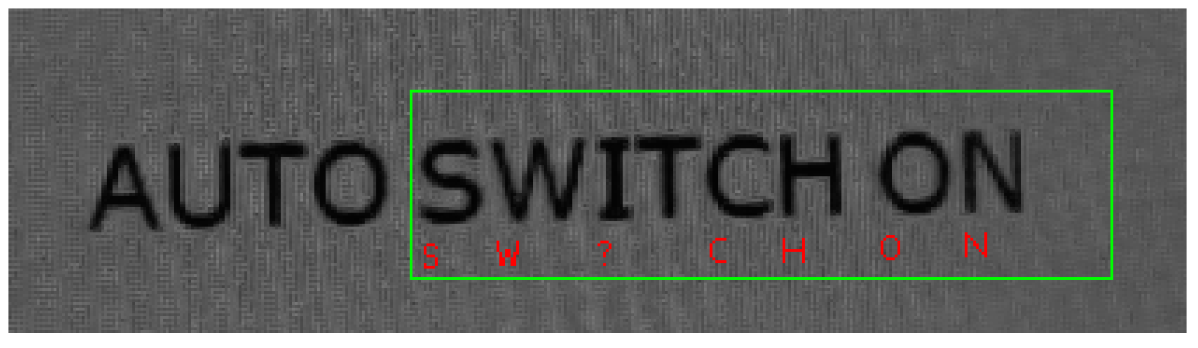
Table 3 shows the recognition performance of different words recognized by the robot. The average recognition rate was 92.4%. “WiFi” and “Open” are difficult words to recognize because of erroneous recognition or unrecognized characters. Performance could be easily improved by the addition of a dictionary process, which increased the recognition accuracy to 99%.
| Word | Recognized % | Problems | Dictionary % |
|---|---|---|---|
| SWITCH | 93.6 | i recognized as J or 1, or not recognized | 97.6 |
| ON | 100 | - | 100 |
| OFF | 100 | - | 100 |
| WiFi | 78.5 | i recognized as l or 1, or not recognized | 100 |
| 97.9 | l recognized as i; o recognized as 0 or d, or not recognized | 99.3 | |
| Maps | 100 | - | 100 |
| Open | 72.4 | o recognized as d; e recognized as o; n recognized as h | 100 |
| 90 | i recognized as l or 1; l recognized as i or 1 | 95 | |
| Hotspot | 99.2 | p not recognized | 99.2 |
5.1. Turn on WiFi
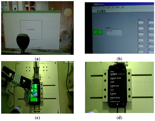
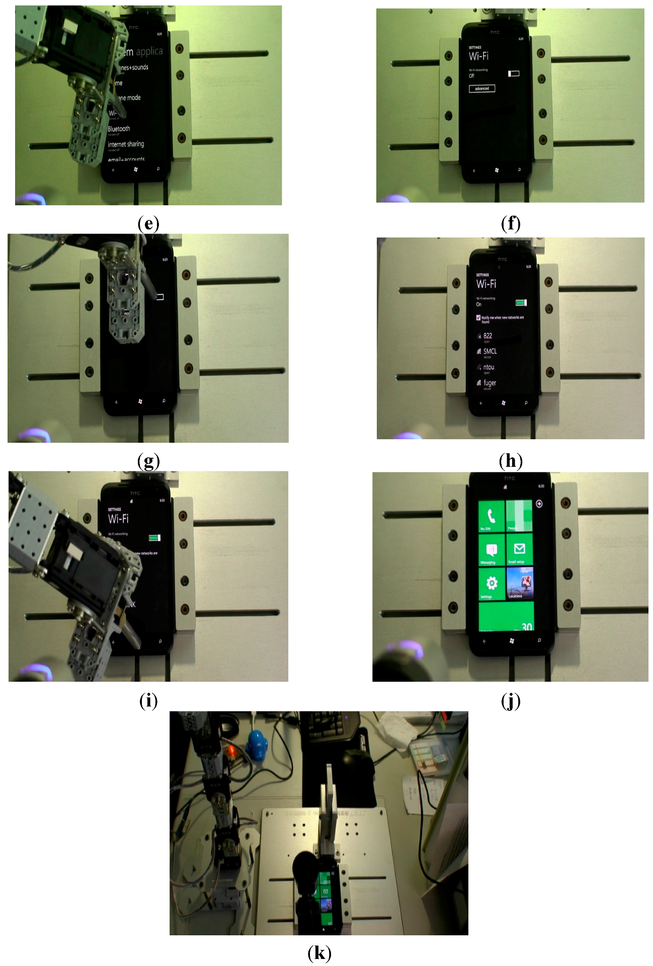
This experiment involved the robot arm turning on the WiFi function, as shown in Figure 27. First, the command Turn on WiFi came from the command panel (PC screen) and the camera (in front of the panel) snapped the words. The signal was sent to the processor (notebook) in real time, and then the robot arm began the assigned movement. After the completion of the whole procedure, the robot arm returned to its original position. The 11 steps are shown in Figure 27.
Figure 27.
Command: Turn on WiFi. (a) Snapped words from command panel (PC screen); (b) Captured words recognized by processor; (c) Move robot arm to touch the setup icon; (d) Robot camera recognizes the WiFi location; (e) Move robot arm to touch the Wi-Fi; (f) Enter WiFi page; (g) Turn on WiFi switch; (h) Check WiFi is “on” by the robot camera; (i) Touch home page icon; (j) Return to home page; (k) Robot arm moves back to original position.


5.2. Send a Message
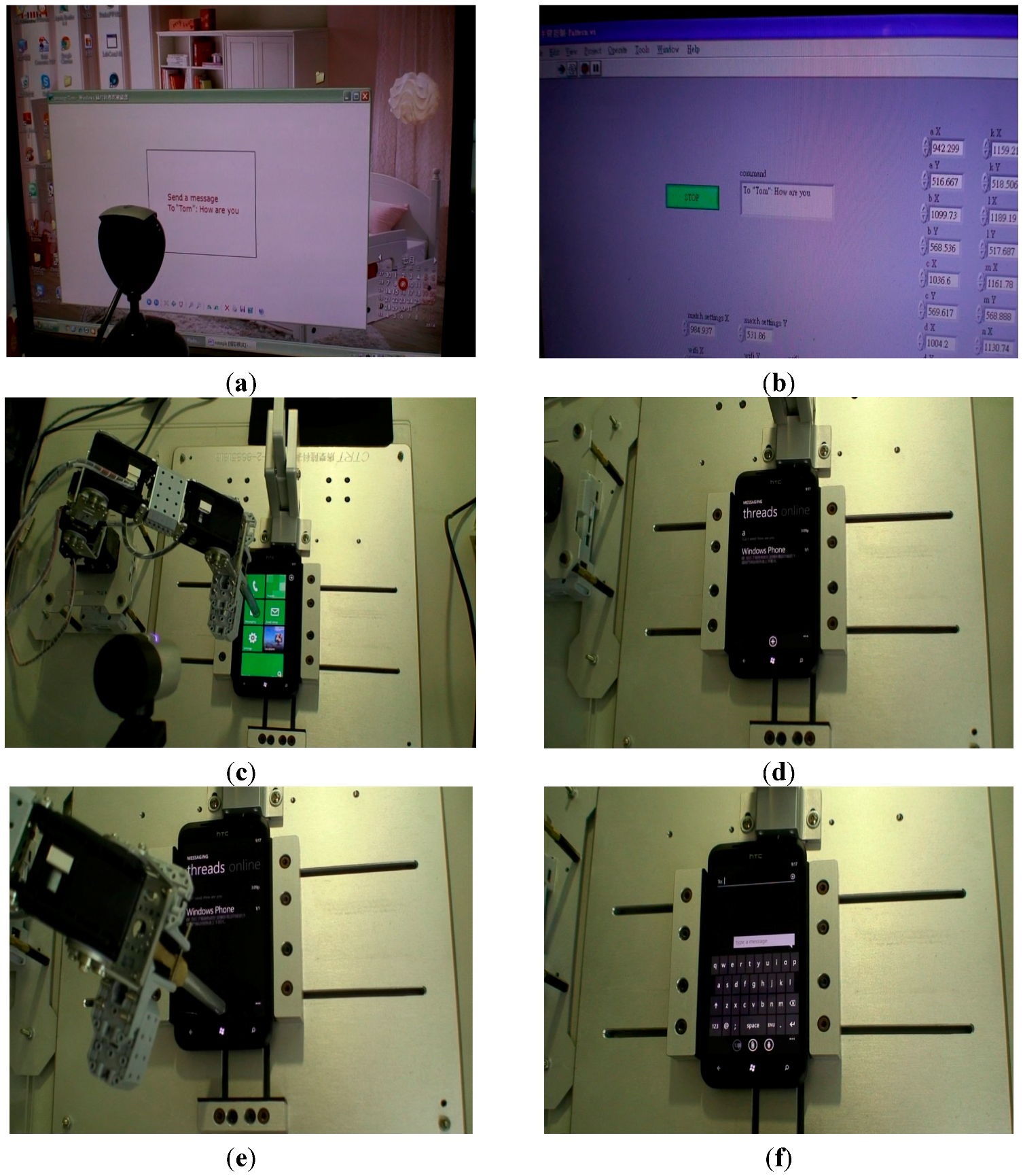
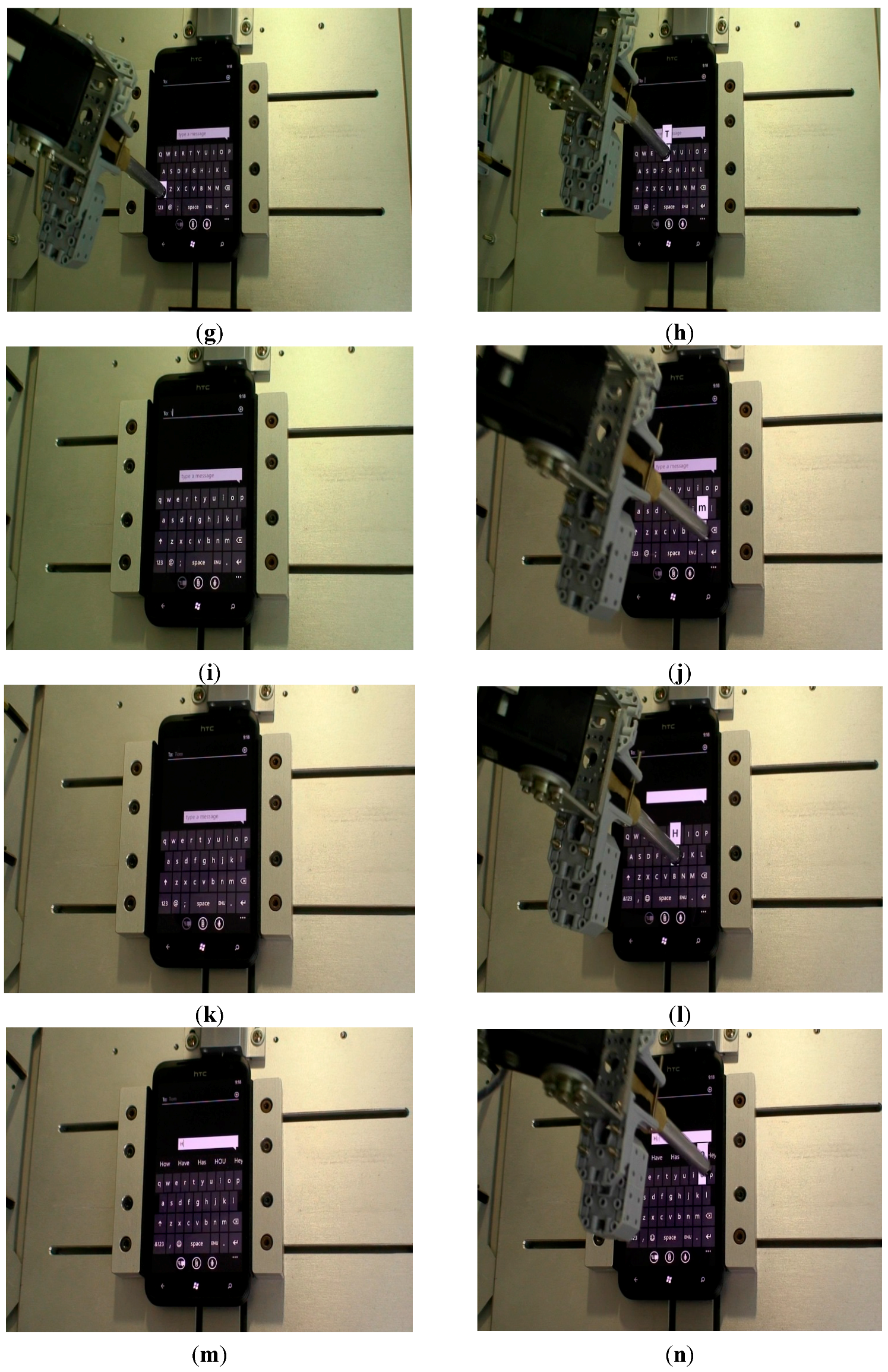
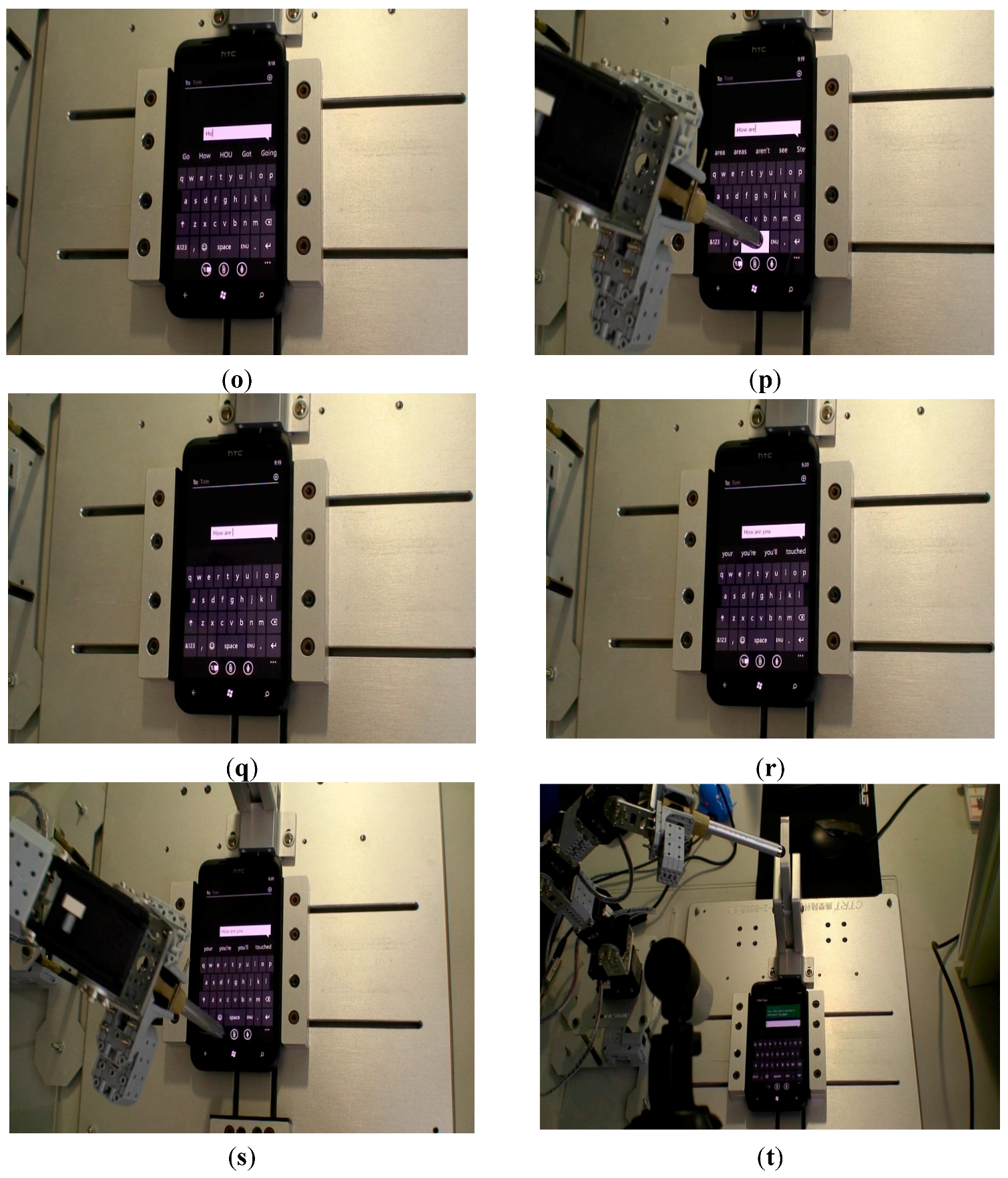
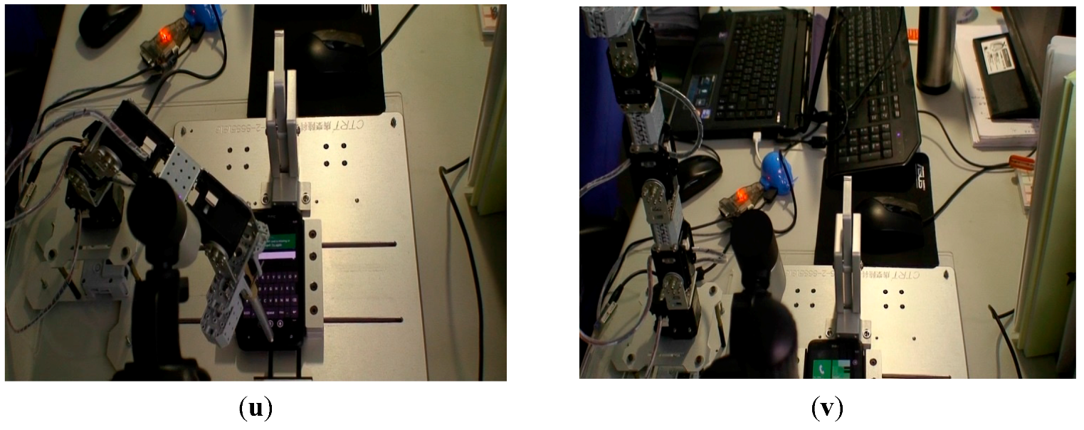
This experiment involved the robot arm typing a message and sending it out, as shown in Figure 28. First, the command Send a message came from the command panel (PC screen) and the camera (in front of the panel) snapped the words. The signal was sent to the processor (notebook) in real time, then the robot arm began the assigned movement. After the completion of the whole procedure, the robot arm returned to its original position. The 22 steps are shown in Figure 28.
Figure 28.
Command: Send a message to “Tom”. (a) Snap words from command panel (PC screen); (b) Captured words recognized by the processor; (c) Move robot arm to touch the message icon; (d) Enter initial message page; (e) Move robot arm to touch the add icon; (f) Enter message page; (g) Press capital switch; (h) Press T; (i) T is identified; (j) Press m; (k) The name “Tom” is identified; (l) Press H; (m) H is identified; (n) Press o; (o) O is identified; (p) Press space; (q) Space is identified; (r) Check the whole message by the robot camera; (s) Press send; (t) Check the message is sent by the robot camera; (u) Touch home page icon; (v) Robot arm moves back to its original position.


6. Conclusions
In this paper, an intelligent scheme based on image processing, pattern recognition, character recognition and fuzzy control was proposed to control a robot arm for realizing position control. Forward kinematics was applied to identify the relationships of each joint of the robot arm. The solution of the forward kinematics was obtained using a Denavit-Hartenberg algorithm. In the image processing, we transformed the RGB color space to HSL color space, which significantly reduced the impact of light. Vision Builder for Automated Inspection allowed us to easily configure and benchmark a sequence of visual inspection steps, as well as deploy the visual inspection system for automated inspection. An optical character recognition program was implemented using VBAI, with the characters corrected by a dictionary process. The character recognition process was performed using 43 features in training data. The VBAI is capable of distinguishing 52 characters of the English language (both uppercase and lowercase letters). In addition, characters could be checked by the use of image processing techniques, and the program also proved capable of recognizing characters in incomplete images. In the control scheme, the control system could obtain the desired position in real time by means of the fuzzy controller. To solve the rule explosion problem in a multi-input fuzzy logic system, a hierarchical fuzzy system was applied in the control design. The human-machine interface was handled by LabVIEW 2010 (National Instruments, Austin, TX, USA) and MALAB codes utilized by the controller. Recognition accuracy was 92.4% for images taken from the webcam and 99% using the dictionary process. The experimental results showed that with the proposed control scheme, the robot arm performed different assigned functions successfully.
Acknowledgments
This research is supported by the EC Laboratory of SGS Taiwan Ltd. (Taipei, Taiwan) under Grand102A60706.
Author Contributions
Drafting of manuscript: Jih-Gau Juang and Yi-Ju Tsai; acquisition of data: Yi-Ju Tsai and Yang-Wu Fan; analysis and interpretation of data: Jih-Gau Juang and Yi-Ju Tsai; Model construction: Jih-Gau Juang, Yi-Ju Tsai and Yang-Wu Fan; and planning and supervision of the research: Jih-Gau Juang.
Conflicts of Interest
The authors declare no conflict of interest.
Appendix A
Kinematic model of robotic arm with four degrees of freedom is derived from the D-H model, as found from the robot arm as analyzed in Figure A1. We can analyze the relationship between each joint, as shown in Table A1.
Figure A1.
The 4R articulated robot arm analyzed by D-H.

| Joint | ||||
| 1 | 0 | 90° | 0 | |
| 2 | 0° | 0 | ||
| 3 | 0° | 0 | ||
| 4 | 0° | 0 |
The aim of forward kinematics is to solve the transformation equations for the end-effectors’ Cartesian position and orientation when the joint angles are given. Homogeneous transformation matrices that transform the motion from one coordinate frame reference to another can be easily obtained from the D-H parameters, as shown in Table A1, using the conventional equations that relate every two consecutive frames to each other as follows [8]:
where s is the sine and c is the cosine of the angle. Applying Equation (A1) to all four reference coordinate frames gives the following homogeneous transformations:
These homogeneous transformations, Equations (A2)–(A5), describe the kinematic behavior of the robotic system at any instance of time. For instance, to find where frame 4 lies based on frame 3 when joint 4 is at a certain angle, substituting that angle in the specified transformation matrix gives the position and orientation of frame 4 based on frame 3. The first 3 × 3 rows and columns of the homogeneous transformation describe frame 4’s unit vector projection on frame 3, and the first three rows of the last column of the homogeneous transformation describe the position of frame 4’s center based on frame 3. Propagating these matrices from one frame to the other gives us the forward kinematics of the robotic arm that describes the end-effector’s frame based on the base frame as follows:
From this point on, we use these transformation matrices as noted above. The rotation matrices and the frame’s center coordinates extracted from these homogeneous transformation matrices are as follows:
where r is the 3 × 3 rotation matrix representation of the transformation; d is the vector containing the X, Y and Z coordinates of the origin of the frame; cij = cos(θi + θj); and sij = sin(θi + θj). Through Equation (A7), any position in the end-effector frame can be mapped in the base frame. Hence, the forward kinematic parameters for the humanoid arm are given by:
The inverse kinematics of the robot manipulators is described as giving the desired end effector’s configuration, namely, position and orientation in the operational space, to determine the joint variables in the joint space. This means we can calculate the required rotation angle of each joint. The inverse kinematics of our robot arm is derived as follows:
From Equation (A11), we have:
From Equation (A19), we have:
From Equations (A17), (A22) and (A28), we have:
Appendix B
The fuzzy rules are given as follows:
- Level 1:
- Rule 1: If DER is negative big, then M3 is NB.
- Rule 2: If DER is negative small, then M3 is NS.
- Rule 3: If DER is zero, then M3 is Z.
- Rule 4: If DER is positive small, then M3 is PS.
- Rule 5: If DER is positive big, then M3 is PB.
- Where DER is the distance error, which is dr minus r, and M3 is θ3.
- Level 2:
- Rule 1: If NER is negative big, then M4 is NB.
- Rule 2: If NER is negative small, then M4 is NS.
- Rule 3: If NER is zero, then M4 is Z.
- Rule 4: If NER is positive small, then M4 is PS.
- Rule 5: If NER is positive big, then M4 is PB.
- Where NER is the new distance error computed by M3 of level 1, which is dr minus the new r, and M4 is θ4.
- Level 3:
- Rule 1: If A2ER is negative big, then M2 is NB.
- Rule 2: If A2ER is negative small, then M2 is NS.
- Rule 3: If A2ER is zero, then M2 is Z.
- Rule 4: If A2ER is positive small, then M2 is PS.
- Rule 5: If A2ER is positive big, then M2 is PB.
- Where A2ER is the angle error of θ2 computed by M4 of level 2, which is θd2 minus θ2, and M2 is θ2.
- Level 4:
- Rule 1: If A1ER is negative big, then M1 is NB.
- Rule 2: If A1ER is negative small, then M1 is NS.
- Rule 3: If A1ER is zero, then M1 is Z.
- Rule 4: If A1ER is positive small, then M1 is PS.
- Rule 5: If A1ER is positive big, then M1 is PB.
- Where A1ER is the angle error of θ1 computed by M2 of level 3, which is θd1 minus θ1, and M1 is θ1.
References
- Manigpan, S.; Kiattisin, S.; Leelasantitham, A. A Simulation of 6R Industrial Articulated Robot Arm Using Backpropagation Neural Network. In Proceedings of the 2010 IEEE International Conference on Robotics & Automation, Anchorage, AK, USA, 3–7 May 2010; pp. 823–826.
- Furuta, K.; Kosuge, K.; Mukai, N. Control of Articulated Robot Arm with Sensory Feedback: Laser Beam Tracking System. IEEE Trans. Ind. Electron. 1988, 35, 31–39. [Google Scholar] [CrossRef]
- Munasinghe, S.R.; Nakamura, M.; Goto, S.; Kyura, N. Optimum Contouring of Industrial Robot Arms under Assigned Velocity and Torque Constraints. IEEE Trans. Syst. Man Cybern. Part C 2001, 31, 159–167. [Google Scholar] [CrossRef]
- Koga, M.; Kosuge, K.; Furuta, K.; Nosaki, K. Corrdinated Motion Control of Robot Arms Based on the Virtual Internal Model. IEEE Trans. Robot. Autom. 1992, 8, 77–85. [Google Scholar] [CrossRef]
- Kennedy, C.W.; Desai, J.P. Modeling and Control of the Mitsubishi PA-10 Robot Arm Harmonic Drive System. IEEE Trans. Mechatron. 2005, 10, 263–274. [Google Scholar] [CrossRef]
- Efe, M.O. Fractional Fuzzy Adaptive Sliding-Mode Control of a 2-DOF Direct-Drive Robot Arm. IEEE Trans. Syst. Man Cybern. Part B 2008, 38, 1561–1570. [Google Scholar] [CrossRef] [PubMed]
- Daud, W.A.B.W.; Faizura, W.; Adly, M.A.; Elamvazuthi, I. Kinematic Modeling of Humanoid Arm. In Proceedings of the 2010 IEEE International Conference on Intelligent and Advanced Systems, Kuala Lumpur, Malaysia, 15–17 June 2010; pp. 1–4.
- Wang, W.J.; Huang, C.H.; Lai, I.H.; Chen, H.C. A Robot Arm for Pushing Elevator Buttons. In Proceedings of the 2010 SICE Annual Conference, Taipei, Taiwan, 18–21 August 2010; pp. 1844–1848.
- Yang, M.; Lu, G.; Li, J. An Inverse Kinematics Solution for Manipulators Based on Fuzzy Logic. In Proceedings of the 2001 IEEE International Conference on Info-Tech and Info-Net, Beijing, China, 29 October–1 November 2001; pp. 400–404.
- Arefi, R.; Sadigh, M.J. Fuzzy Inverse Kinematics Algorithm for Man and Machine Cooperation. In Proceedings of the 2011 IEEE International Conference on Mechatronics, Istanbul, Turkey, 13–15 April 2011; pp. 398–402.
- Bulanon, D.M.; Kataoka, T.; Okamoto, H.; Hata, S. Development of a Real-time Machine Vision System for the Apple Harvesting Robot. In Proceedings of the Annual Conference on SICE, Sapporo, Japan, 4–6 August 2004; pp. 595–598.
- Kragic, D.; Björkman, M.; Christensen, H.I.; Eklundh, J.O. Vision for Robotic Object Manipulation in Domestic Settings. Robot. Auton. Syst. 2005, 52, 85–100. [Google Scholar] [CrossRef]
- Lttoumeau, D.; Michaud, F.; Valin, J.M.; Proulx, C. Textual Message Read by a Mobile Robot. In Proceedings of the 2003 IEEE International Conference on Intelligent Robots and Systems, Las Vegas, NV, USA, 27–31 October 2003; pp. 2724–2729.
- Qadri, M.T.; Asif, M. Automatic Number Plate Recognition System for Vehicle Identification Using Optical Character Recognition. In Proceedings of the 2009 IEEE International Conference on Education Technology and Computer, Singapore, 17–20 April 2009; pp. 335–338.
- Tsai, P.C. Based on Inverse Kinematics for Robot Arm Control. Master’s Thesis, Department of Electrical Engineering, National Central University, Chungli, Taiwan, 2011. [Google Scholar]
- Vision Builder for Automated Inspection. Available online: http://www.ni.com/webcast/86/en/ (accessed on 8 March 2014).
- Peng, Y.L. A Video Surveillance System for Missing Object Detection with Reporting Capability. Master’s Thesis, Department of Computer Science and Information Engineering, National Central University, Chungli, Taiwan, 2009. [Google Scholar]
- Michaud, F.; Lttoumeau, D. Mobile Robot that can read symbols. In Proceedings of the 2001 IEEE International Symposium on Computational Intelligence in Robotics and Automation, Banff, AB, Canada, 29 July–1 August 2001; pp. 338–343.
- Pham, L.M.; Le, H.T.; Muddu, R.; Ryu, D. Real-time Eye Tracking Using a Smart Camera. In Proceedings of the 2011 IEEE Applied Imagery Pattern Recognition Workshop, Washington, DC, USA, 11–13 October 2011; pp. 1–7.
- Labview Discussion Page. Available online: http://www.labviewpro.net/forum_result.php?fid=1&changetype= 1&keyword=vision (accessed on 12 January 2013).
- Raju, G.V.S.; Zhou, J. Adaptive Hierarchical Fuzzy Control. IEEE Trans. Syst. Man Cybern. 1993, 23, 973–980. [Google Scholar] [CrossRef]
© 2015 by the authors; licensee MDPI, Basel, Switzerland. This article is an open access article distributed under the terms and conditions of the Creative Commons Attribution license (http://creativecommons.org/licenses/by/4.0/).
Share and Cite
MDPI and ACS Style
Juang, J.-G.; Tsai, Y.-J.; Fan, Y.-W. Visual Recognition and Its Application to Robot Arm Control. Appl. Sci. 2015, 5, 851-880. https://doi.org/10.3390/app5040851
AMA Style
Juang J-G, Tsai Y-J, Fan Y-W. Visual Recognition and Its Application to Robot Arm Control. Applied Sciences. 2015; 5(4):851-880. https://doi.org/10.3390/app5040851
Chicago/Turabian StyleJuang, Jih-Gau, Yi-Ju Tsai, and Yang-Wu Fan. 2015. "Visual Recognition and Its Application to Robot Arm Control" Applied Sciences 5, no. 4: 851-880. https://doi.org/10.3390/app5040851