Development of Novel Test Specimens for Characterization of Multi-Material Parts Manufactured by Material Extrusion


1
Institute for Engineering Design, Technische Universität Braunschweig, Brunswick 38106, Germany
2
Fraunhofer Research Institution for Additive Manufacturing Technologies IAPT, Hamburg 21029, Germany
*
Author to whom correspondence should be addressed.
Appl. Sci. 2018, 8(8), 1220; https://doi.org/10.3390/app8081220
Submission received: 11 July 2018
/
Revised: 20 July 2018
/
Accepted: 23 July 2018
/
Published: 25 July 2018
(This article belongs to the Section Mechanical Engineering)
Abstract
:Multi-material additive manufacturing (AM) offers new design opportunities for functional integration and opens new possibilities in innovative part design, for example, regarding the integration of damping or conductive structures. However, there are no standardized test methods, and thus test specimens that provide information about the bonding quality of two materials printed together. As a result, a consideration of these new design potentials in conceptual design is hardly possible. As material extrusion (ME) allows easily combination of multiple polymeric materials in one part, it is chosen as an AM technique for this contribution. Based on a literature review of commonly used standards for polymer testing, novel test specimens are developed for the characterization of the bonding quality of two ME standard materials printed together. The proposed specimen geometries are manufactured without a variation of process parameters. The load types investigated in the course of this study were selected as examples and are tensile, lap-shear, and compression-shear. The conducted tests show that the proposed test specimens enable a quantification of the bonding quality in the material transition. Moreover, by analyzing the fracture pattern of the interface zone, influencing factors that probably affect the interface strength are identified, which can be further used for its optimization.
1. Introduction
Multi-material parts manufactured by additive manufacturing (AM), also known as 3D printing, demonstrate a vast potential regarding the integration of multiple, material-specific functions. For example, differences in stiffness of two different materials can be used in such a way that damping functions are locally integrated [1,2]. Moreover, conductive materials can be combined with conventional build materials in order to realize conductivity inside specific areas of the part, so that the assembly and maintenance of radiant heat surfaces [3] or 3D printed circuits would be omitted [4]. Using AM technologies to generate multi-material parts enables the possibility of achieving custom-designed requirements by means of functional integration via local material variations and a specific design of material properties. Hence, in contrast to traditional manufacturing processes (e.g., milling or casting), the designer has entirely new opportunities in product design. Consequently, there are two big challenges. On the one hand, the design engineer needs to be supported to ensure a consideration of these new design potentials in conceptual design. On the other hand, standardized test methods for analyzing both the compatibility and the bonding quality of two materials printed together have to be established. The latter research gap is focused on in this contribution.
Whereas only a few AM technologies are capable of processing multiple materials within the printing process, the AM technique material extrusion (ME) is due to its process principle (discrete material transition) predestinated in this regard [5]. In fact, only the number of extruders integrated into the ME machine limits the number of processable materials—even within one layer [6]. A multi-material part design framework supporting the selection of suitable material combinations for additively manufactured parts has already been proposed by Yao et al. [7]. However, the quantification of the interface strength (bonding quality) between two different polymeric materials and a compatibility in general are inadequately discussed. As the compatibility is closely linked to the corresponding mechanical properties in the interface zone, a quantification of those is indispensable for designing multi-material parts for ME. Yet, standardized test methods and test specimens for multi-material ME parts are not available. As a consequence, users have no common basis on which mechanical properties of two combined thermoplastic materials can be determined. A standard that shall enable an efficient and clear communication between users (here, suppliers of additively manufactured parts and their customers) is addressed in DIN EN ISO/ASTM 52901 [8], but multi-material parts are not considered.
In this paper, novel specimens for the three exemplary load types, namely, tensile, lap-shear, and compression-shear, are proposed. With ABS (acrylonitrile butadiene styrene) and PLA (polylactic acid), two standard materials from the prototyping sector are used as reference materials. The proposed test methods, including the development of novel tests specimens for characterization of multi-material ME parts, are experimentally validated.
2. Test Methods for ME
This section gives an overview of the material extrusion principle with regard to multi-material designs and the mechanical testing of polymers in general, as well as for ME printed test specimens in particular.
2.1. Material Extrusion
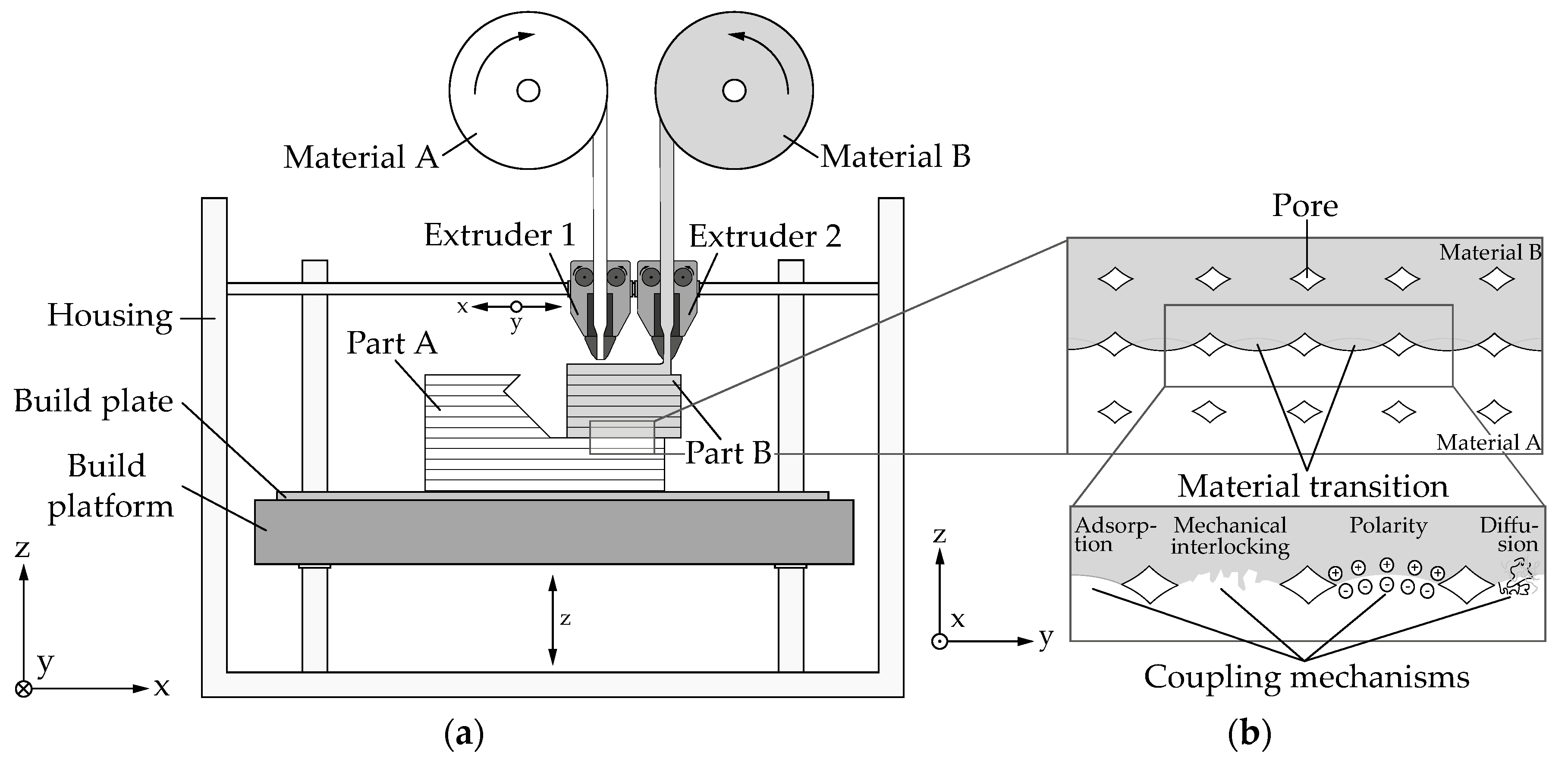
The AM technique material extrusion (also, fused deposition modeling—FDM, trademark of Stratasys—or fused filament fabrication—FFF, non-commercial name) is characterized by an extrusion of a thermoplastic material (see Figure 1). For this purpose, a polymeric stock material (filament) is directed via conveyor unit into an extruder, plasticized, and applied to the previous layer in accordance with the cross section to be generated [6]. As a result of thermal fusion, the applied layer bonds with the surrounding layers and solidifies shortly after. The part is thus built up layer by layer.
Figure 1a shows the ME principle schematically. It can be seen that several materials are, in principle, processable within one layer. The range of materials available in this respect involves commodity, engineering, and high performance plastics [6]. However, combining material A and B commonly depends on their respective glass transition temperature (Tg) (temperature range in which a plastic is subject to the greatest change in its deformability) or heat distortion temperature (HDT) (softening temperature under a specific load). Only materials with similar transition temperatures allow a combination in the form of a multi-material ME part. As a major gap in these temperatures results in warping (deformation induced by residual thermal stresses) of the material with the higher value, a combination of, for instance, commodity plastics (e.g., PLA, Tg = 55–60 °C [9] or ABS, Tg = 105 °C [10]) and high performance plastics (e.g., PEI (polyetherimide), trade name ULTEM [11], Tg = 186 °C) is commonly not possible.
An interface zone in which two different plastic materials are successfully combined, on the other hand, shows a distinct overlap region (see. Figure 1b). The development of this region is primarily characterized by three successive steps [12]: first, the surfaces of material A and B come into contact; second, a neck (interface zone) grows between these two strands driven by surface tension; third, a molecular diffusion and randomization of the different polymer chains within this neck take place. Further coupling mechanisms relevant for the interface zone are adsorption, polarity, and mechanical interlocking [13]. Adsorption is considered as a pre-condition for initial bonding in the material transition, followed by electrical polarity, such as dipoles, that are present in oxides, hydroxides, hydroxyl groups, and so on in the interface layers. These polarities initiate interactions that cause an increase of adhesion between two corresponding layers [14]. Mechanical interlocking, however, is based on undercuts that generate a coupling in the material transition.
In general, the mechanical properties of multi-material ME parts are correlated to the bonding quality in the interface zone. This is primarily affected by the characteristics of the distinct overlap region in the material transition caused by neck growth and intermolecular diffusion [12].
2.2. Mechanical Testing of Plastics
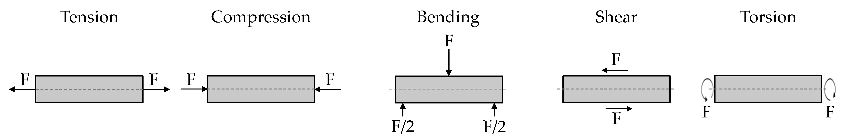
Mechanical testing of plastics is used to investigate and determine mechanical properties of polymeric test specimens using standardized test methods compiled, for example, by American Society for Testing and Materials (ASTM), International Organization for Standardization (ISO), or Deutsches Institut für Normung (DIN). The mechanical behavior of plastic materials is characterized by tension (σ) and elongation (ε). Depending on the major load types, a distinction can be made between tensile, compression, and bending stresses (see Figure 2). For tensile and compression stresses—so called normal stresses (σ)—a force (F) applies vertically on the loaded surface. Bending stresses, as well as normal stresses, can be considered as a superposition of tensile and compression stresses and are calculated by the quotient of bending moment (Mb) and section modulus (Wb). If the force is not applied vertically but in the surface, shear stresses (τ) emerge. The corresponding load types are shear and torsion. For the latter, shear stresses are calculated by the quotient of torsional moment (Mt) and polar section modulus (Wp) [14].
Test methods can be further distinguished by the speed during execution. Whereas for static tests, a steady speed is performed, the speed of quasi-static tests is slowly increasing. Dynamic tests, on the other hand, are characterized by a non-uniform load application. Within these ranges of speed, test methods are subdivided according to the major load types (tension, compression, and bending). In addition, for quasi-static tests, torsion and shear tests are conducted as well [15].
To obtain comparable values for the mechanical properties of different plastics, test methods must be conducted under equal test conditions regarding speed, ambient temperature, and relative humidity. As thermoplastics show viscoelastic material behavior above the glass transition temperature, mechanical properties are significantly affected by the ambient temperature. Besides, some plastics (e.g., PLA and ABS) are hygroscopic, so the moisture content also has a major impact on the mechanical properties. In general, the ambient temperature and relative humidity are set at 23 °C and 50%, respectively. [14]
2.3. Mechanical Testing of ME Printed Test Specimens
This section gives an overview of the state-of-the-art regarding mechanical testing of ME printed test specimens. Besides the three major load types, shear is also considered because of its relevance in the following sections.
Current standards regarding the main characteristics and corresponding test methods for additively manufactured test specimens can be found in DIN EN ISO 17296-3 [16]. While these standards most closely correspond to standard test methods for plastics, AM specific tests in accordance with these standards must specifically refer to the properties of the additively manufactured test specimens, for example, anisotropy. As a consequence, AM specific standards are currently under development (e.g., ISO/TC 261).
An overview of test methods conducted for ME printed test specimens for the three major load types and shear is given in Table 1. The following research studies propose optimization approaches for additively manufactured parts that are intended to withstand maximum loads by selecting the process parameter sets for ME. In addition, some research studies [17,18] investigate the adhesion between printed strands by varying process parameters, such as temperature, layer thickness, and layer design, to improve inter-layer cohesion and strength. However, only test specimens made of one build material are investigated. Test methods for multi-material ME parts and, more specifically, the quantification of the interface strength between two different materials are not sufficiently proposed yet.
3. Experimental
In this section, the development of test specimens for the characterization of multi-material ME parts depending on different load types, as well as the experimental set-up, are discussed.
3.1. Development of Novel Test Specimens for Multi-Material ME
In comparison to DIN 8593 [39], the type of bonding corresponds to the welding of plastics. This is, in a limited sense, similar to diffusion adhesive bonding because of molecular interactions without an additional adhesive. As a result, the multi-material ME process can be approximated by these processes.
In this paper, test specimens for tensile strength, lap-shear strength, and compression-shear strength are exemplarily developed according to established testing standards. For testing tensile strength, DIN EN 15870 [40] is utilized for butt joints and DIN EN 12814-2 [41] is used for welded joints of thermoplastics. Lap-shear strength (eccentric) of bonded assemblies is standardized for adhesives in DIN EN 1465 [42] and structural adhesives in DIN EN 14869-2 [43]. A method for testing shear strength resulting from compression is described in DIN EN ISO 13445 [44].
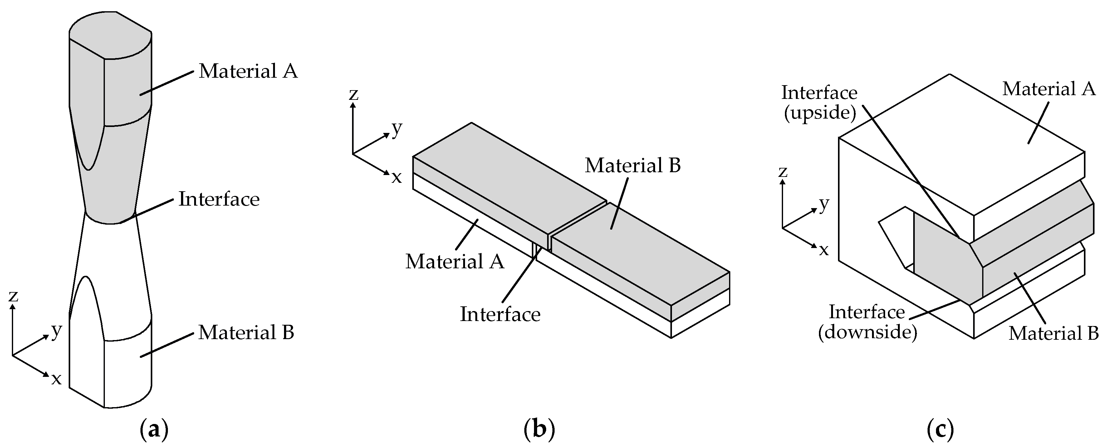
Based on these standards, test specimens are designed by considering ME design guidelines (see Figure 3). Thus, no support material (printed structures made of build or soluble material necessary for printing overhangs with an angle to the build platform smaller than 45°) is required as all overhangs are designed to be bridged (printing short distances between two anchor points without support).
To ensure a combined processing of different materials, the glass transition temperature or heat distortion temperature of both materials has to be considered in determination of the build platform and/or build chamber temperature. Consequently, there is no material change in the first layers of the specimen, because two different materials vary in their Tg values and shrinkage behavior. Hence, a material change in the first layers could lead to a failure in layer bonding, which can result in delamination. Avoiding this, a uniform temperature conditioning on the build platform and/or in the build chamber close to the glass transition temperature of the material with the lower Tg value needs to be considered. This is valid until a certain threshold value for the difference of the glass transition temperatures is reached (cf. PLA/PEI).
The specimens are designed in such a way that the interface zone represents the weakest part of the geometry, so bending is prevented. To further prevent tipping, the height of the tensile specimen (a) and the thickness of the lap-specimen (b) are designed accordingly. All dimensions of the test specimens are shown in Figure 4. The z-axis represents the build direction and the xy-plane is parallel to the build platform.
3.2 Experimental Set-Up
As PLA and ABS are commonly used in ME, especially for prototyping, these two standard polymers are selected in order to validate the development of novel test specimens for characterization of multi-material ME parts. For printing them, the pro-consumer machine Ultimaker 3 by Ultimaker B.V. (Geldermalsen, Netherlands) with a dual extrusion system is used. The 3D printer comes with a heated build platform, but no actively heated build chamber. The build platform temperature is set to 60 °C because of the fact that PLA has a lower glass transition temperature (Tg ≈ 60 °C) than ABS (Tg ≈ 105 °C). The PLA is processed directly on the build platform (glass plate) with no other adhesion increasing material in between. The material was obtained from DAS FILAMENT [9], whereas the ABS is purchased from Innofil3D [10]. Table 2 shows the used parameters for printing the test specimens. All specimens are printed on the same machine and with an identical calibration set-up.
Before starting the printing process, the materials are dried: PLA at a temperature of 45 °C and ABS at 60 °C, for 4 h each. To ensure equal environmental conditions during the printing process, the filaments are directly processed from a filament storage box that regulates relative humidity at 17–20%. Before testing, all specimens are stored at 23 °C ambient temperature and a relative humidity of 45–50% for at least one week in the laboratory. For the mechanical testing, the universal testing system Instron 5966 (Instron® GmbH, Darmstadt, Germany) with a 10 kN load cell is used and all specimens are clamped by a locking torque of 12 Nm. The tests are performed at 24 °C ambient temperature, a relative humidity of 43%, and a constant testing speed of 2 mm per minute.
4. Results and Discussion
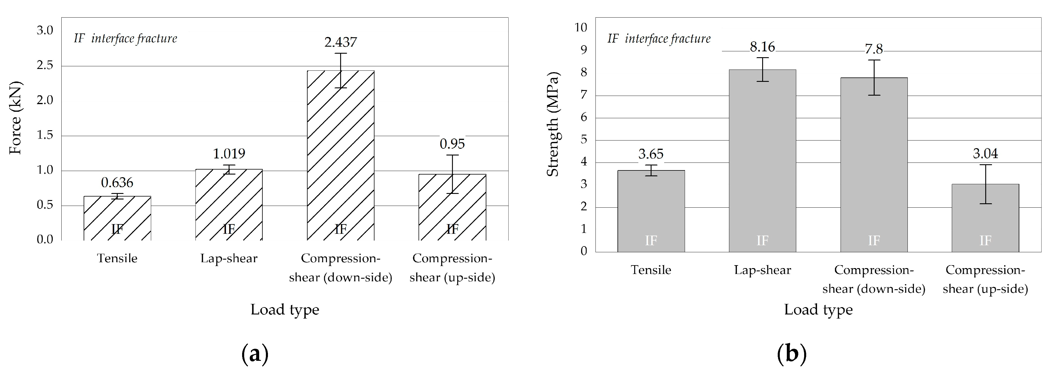
In this section, the results of the experimental investigations are presented and discussed. Figure 5 shows the median of the corresponding force and strength each with standard deviation of the multi-material test specimens classified by load type. As both material transition zones failed separately—suggesting a difference in the interface zones—the result of the compression-shear test is divided into two values. This is probably caused by a difference in printing order and glass transition temperatures.
It can be seen that the standard deviation validates the developed geometry of test specimens for testing multi-material parts manufactured by ME. However, because of comparatively low interface strength of the representatively chosen material combination PLA and ABS, uncertainties regarding the printing process (e.g., machine calibration or fluctuations in filament diameter) or testing procedure (e.g., tipping because of fixation) have a strong impact on the mean variation of the maximum strength. All specimens failed in the material transition zone because of interface fracture. The tensile and lap-shear test specimens show the lowest standard deviation of about 6.5%. The corresponding values are 39.70 N/0.24 MPa (tensile tests) and 65.49 N/0.53 MPa (lap-shear tests), respectively. On the contrary, the results of compression-shear tests show a standard deviation of about 10%, which equates to a deviation of 248.18 N in force and 0.79 MPa in strength. As a result of a lower layer bonding on the upside, where PLA is deposited on ABS, the transmittable force and resultant strength is about 2.5 times lower and the standard deviation is about three times higher relative to applied forces. The lower layer bonding most likely corresponds to abnormalities in machine calibration; it could be identified that the PLA processing nozzle had a larger distance to the ABS surface, which resulted in pores and a weaker initial bonding. In addition, because of the lower extrusion temperature of PLA and higher glass transition temperature of ABS, the diffusion at the upside interface is probably lower than on the downside.
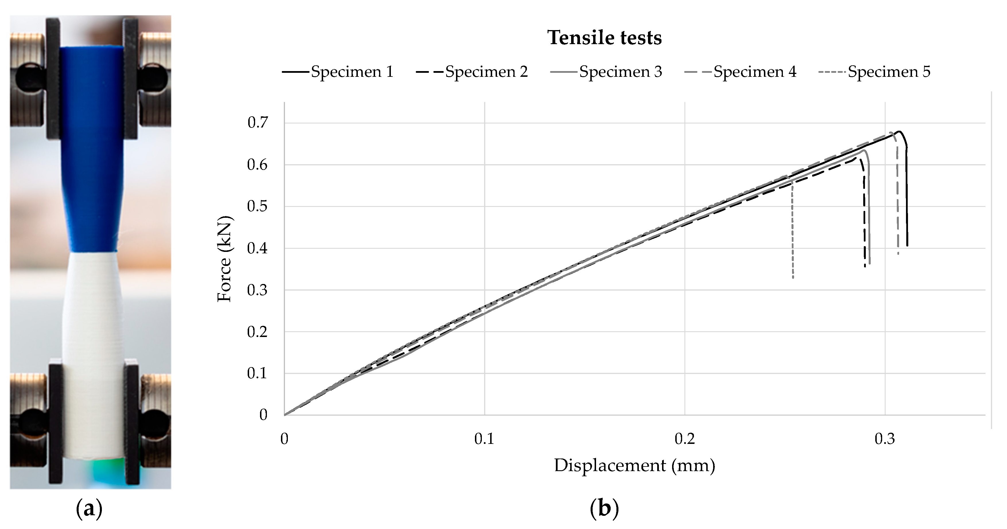
The experimental set-up and the force-displacement curve for the conducted tensile tests are shown in Figure 6. All specimens are clamped with a clamping length of 60 mm. The result indicates a regular increase of the force and a brittle fracture behavior with a low deformation. Apart from specimen 5, the transmittable forces are close together—between 0.62 kN and 0.68 kN.
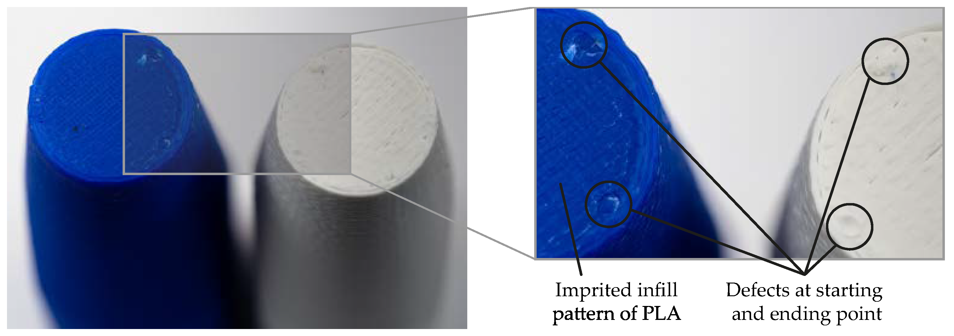
However, each specimen shows a minor defect at the starting and ending point of the outer shell in the fracture pattern. That can cause a general reduction of the maximum strength because they are located at the stress peak of the interface (see Figure 7). As specimen 5 shows no abnormalities in fracture pattern, the reduction of tensile strength could be the result of an error in clamping, for instance, because of an additional bending moment caused by an inclination of the specimen.
The lap-shear specimens are clamped with a clamping length of 50 mm. The thickness of specimens is selected in such a way that the bending moment is minimized. However, in the experimental set-up of the lap-shear tests (see Figure 8a), a deformation of the PLA part can be seen as a result of the shrinkage of ABS caused by cooling after the printing process. Essentially, the highest deformation is located on the edges, even in the material transition. As a result of the thermal shrinkage, residual stresses are introduced. However, these stresses are probably reduced by the build table temperature that warms up the PLA part of the specimen to close too the glass transition temperature. The results of the lap-shear tests are shown in Figure 8. These experimental results show a low deviation of maximum force, except for specimen 4. The values for specimen 1, 2, 3, and 5 range between 1.03 kN and 1.07 kN. Compared to the tensile tests, the displacement is about three times higher. In addition, the increase of the force is not regular, but jagged with few decreases of the shear force, which indicates a partial separation of the two materials.
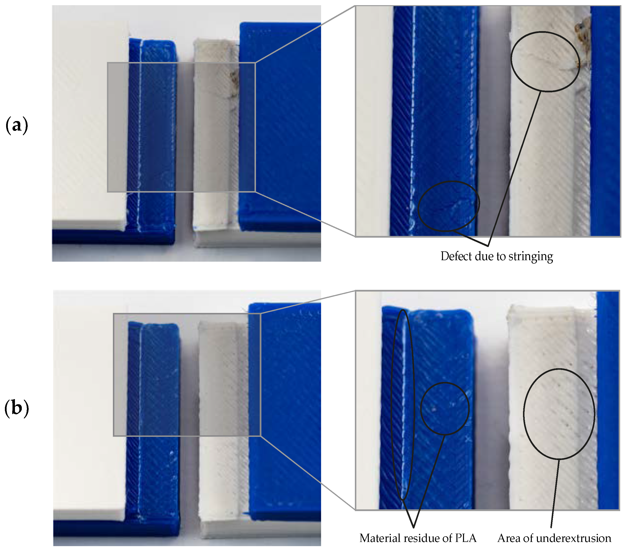
Figure 9 illustrates the failure pattern of lap-shear specimen 3 (a) and specimen 4 (b). In contrast to the tensile tests, material residues of PLA are visible on the ABS surface. This can result from both a higher temperature in the material transition due to the heated build platform, and a force transmission parallel to the layer. In the case of shear force, the surface roughness supports the mechanical coupling and improves the maximum lap-shear strength. The decrease of force of specimen 3 is most likely initiated by a defect in the material transition due to small unwanted strands of plastic called stringing (see Figure 9b). An underextrusion, on the other hand, in the PLA part, can be the reason for premature failure of specimen 4 (Figure 9b). Besides, a decrease of force at 0.3 mm displacement is noticeable for all specimens, which is comparable to the point of failure of the tensile specimens. This decrease probably results from the front surface’s bonding of the PLA part to the ABS interface because material residues of PLA are visible in the material transition of the ABS part (see Figure 9a,b).
The load-displacement curve of the compression-shear tests in Figure 10 shows that the load remains at zero until the specimens reach an extension of about 0.3 mm, because they are not clamped in the clamping jaws at the beginning of testing. For specimen 1, 2, 4, and 5, the values of maximum force range from 2.34 kN to 2.75 kN, at which the displacement lies in a range of about 0.8 mm to 0.9 mm, which corresponds to the displacement of the lap-shear tests. However, specimen 3 already fails at 2.03 kN and a displacement of about 0.7 mm. The standard deviation of maximum transmittable force is about 10.2%, and is consequently higher than in the tensile and lap-shear tests. Furthermore, two decreases of force can be seen in the force-displacement curve, which represent the failures of interface on the downside (second peak) and upside (first peak) related to the build direction during the printing process.
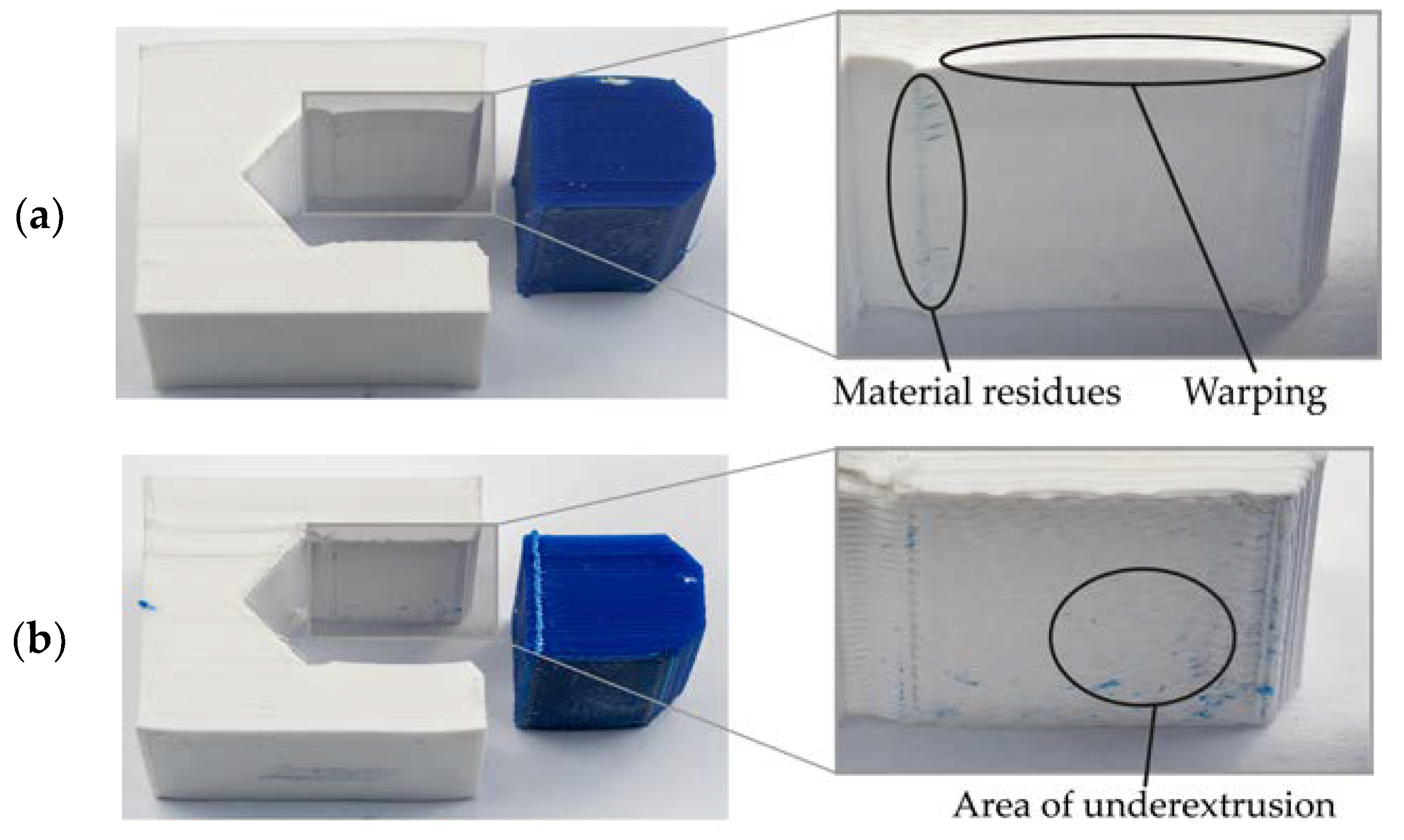
The first decrease of force at about 0.6 mm displacement arises from the failure of the upside at which PLA is processed on the ABS surface (see Figure 11b). This possibly results from both an underextrusion due to abnormalities in machine calibration and a decrease in layer bonding caused by the lower extrusion temperature of PLA combined with the higher glass transition temperature of ABS. Hence, there is a lower polymer chain entanglement (diffusion). In addition, a deformation of the PLA interface at the downside is visible, because ABS significantly shrank during the printing process. This is comparable to the lap-shear specimens. Probably, the geometry of the deformation enhances the maximum transmittable force. Moreover, as a result of the higher extrusion temperature of ABS, PLA’s lower glass transition temperature and the low distance to the heated build platform caused a higher mobility of the polymer chains at the downside so that a stronger entanglement took place.
5. Conclusions
This paper has presented a development of novel test specimens for characterization of multi-material parts manufactured by ME based on standards for mechanical testing of plastics and bonds. As PLA and ABS are commonly used materials for the ME process, they were chosen for the conducted experimental investigations. The developed test specimens for the exemplary load types tensile, lap-shear, and compression-shear were manufactured and tested in accordance with standards for each corresponding load type. The test results show that the conducted test methods, including the proposed test specimens, enable a quantification of the bonding quality in the material transition of ABS and PLA. Thus, the design of ME multi-material parts with respect to the interface strength is possible. However, process parameters (e.g., build platform and printing temperature of PLA [18]) and material properties (e.g., glass transition temperature) affect the resultant interface strength and have to be considered for designing multi-material ME parts. Hence, the developed test specimens can be utilized for the identification of influencing factors on the interface strength with regard to the load type and, in addition, for its optimization.
Further research will concentrate on both an explicit analysis on process-specific influencing factors on the interface strength and a development of methods for its improvement considering additive manufacturing’s design freedom. Another focus is on an elaboration of test specimens for other load types, for example, bending and torsion. The applicability of the presented specimen geometries on hard/soft material combinations needs to be examined, and they probably have to be adapted because of their significantly different mechanical behavior. In addition, different positions of the interface zones, for example, within a layer and variable geometries in the material transition, such as a diagonal interface in z direction, will be investigated. A long-term aim is the development of a method for supporting conceptual and detail design of multi-material ME parts for a goal-oriented integration of specific functions, for example, thermal radiation, electric conductivity, or damping. The presented work plays a key role in this method.
Author Contributions
H.W., L.W., and C.S. conducted the conceptualization of the paper and developed the test methodologies and specimen geometries. H.W. manufactured all specimens. The experimental investigations are performed and analyzed by H.W. and L.W. H.W. and L.W. wrote the original draft of the manuscript. T.V. supervised the research and contributed revision and editing of the manuscript.
Funding
This research received no external funding.
Acknowledgments
We acknowledge support by the German Research Foundation and the Open Access Publication Funds of the Technische Universität Braunschweig.
Conflicts of Interest
The authors declare no conflict of interest.
References
- Rothe, S.; Watschke, H.; Langer, S.C. Study on the producibility of additively manufactured acoustic black holes. In Proceedings of the International Congress on Sound and Vibration 24 (ICSV), London, UK, 23–27 July 2017. [Google Scholar]
- Rothe, S.; Blech, C.; Watschke, H.; Vietor, T.; Langer, S.C. Numerical modelling of additively manufactured acoustic black holes. In Proceedings of the Inter-Noise 2018 47th International Congress and Exposition on Noise Control Engineering, Chicago, IL, USA, 26–29 August 2018. [Google Scholar]
- Watschke, H.; Rautenberg, D.; Waalkes, L.; Junior, C.S.; Vietor, T. Integration of conductive functions based on Fused Layer Modeling. In Proceedings of the 14th Rapid.Tech Conference, Erfurt, Germany, 20–22 June 2017; Kynast, M., Eichmann, M., Witt, G., Eds.; Carl Hanser: Munich, Germany, 2017; pp. 419–432. [Google Scholar] [CrossRef]
- Gnanasekaran, K.; Heijmans, T.; van Bennekom, S.; Woldhuis, H.; Wijnia, S.; de With, G.; Friedrich, H. 3D printing of CNT- and graphene-based conductive polymer nanocomposites by fused deposition modeling. Appl. Mater. Today 2017, 9, 21–28. [Google Scholar] [CrossRef]
- Vaezi, M.; Chianrabutra, S.; Mellor, B.; Yang, S. Multiple material additive manufacturing—Part 1: A review. Virtual Phys. Prototyp. 2013, 8, 19–50. [Google Scholar] [CrossRef]
- Gibson, I.; Rosen, D.; Stucker, B. Additive Manufacturing Technologies: 3D Printing, Rapid Prototyping and Direct Manufacturing, 2nd ed.; Springer: New York, NY, USA, 2015; pp. 147–160. ISBN 978-1-4939-2113-3. [Google Scholar]
- Yao, X.; Ki Moon, S.; Bi, G.; Wei, J. A multi-material part design framework in additive manufacturing. Int. J. Adv. Manuf. Technol. 2018, 1–9. [Google Scholar] [CrossRef]
- DIN Deutsches Institut für Normung e. V. Additive Manufacturing—General Principles—Requirements for Purchased AM Parts (ISO/ASTM 52901:2017); DIN EN ISO/ASTM 52901:2018-03—Entwurf; Beuth Verlag GmbH: Berlin, Germany, 2018. [Google Scholar]
- Technical Data Sheet—NatureWork Ingeo™ Biopolymer 4043D. Available online: https://www.natureworksllc.com/~/media/Files/NatureWorks/Technical-Documents/Technical-Data-Sheets/TechnicalDataSheet_4043D_3D-monofilament_pdf.pdf?la=en (accessed on 3 July 2018).
- Technical Data Sheet—ABS by Innofil3D BV, Version No.: 2.0. Available online: https://www.innofil3d.com/wp-content/uploads/2016/05/TDS-Innofil3D-ABS-160609.pdf (accessed on 3 July 2018).
- Technical Data Sheet—ULTEMTM 9085 by Stratasys, Ltd. Available online: http://usglobalimages.stratasys.com/Main/Files/Material_Spec_Sheets/MSS_FDM_ULTEM9085.pdf (accessed on 3 July 2018).
- Sun, Q.; Rizvi, G.M.; Bellehumeur, C.T.; Gu, P. Effect of processing conditions on the bonding quality of FDM polymer filaments. Rapid Prototyp. J. 2008, 14, 72–80. [Google Scholar] [CrossRef]
- Awaja, F.; Gilbert, M.; Kelly, G.; Fox, B.; Pigram, P.J. Adhesion of polymers. Progress Polym. Sci. 2009, 34, 948–968. [Google Scholar] [CrossRef]
- Troughton, M.J. Handbook of Plastics Joining: A Practical Guide, 2nd ed.; Elsevier: New York, NY, USA, 2009; pp. 145–173. ISBN 978-0-8155-1581-4. [Google Scholar]
- Naranjo, A.; del Pilar Noriega, M.; Osswald, T.; Roldan-Alzate, A.; Sierra, J.D. Plastics Testing and Characterization: Industrial Applications; Carl Hanser: Munich, Germany, 2008; pp. 185–261. ISBN 978-3-446-41315-3. [Google Scholar]
- DIN Deutsches Institut für Normung e. V. Additive Manufacturing—General Principles—Part 3: Main Characteristics and Corresponding Test Methods (ISO 17296-3:2014); DIN EN ISO 17296-3:2016-12; Beuth Verlag GmbH: Berlin, Germany, 2016. [Google Scholar]
- Arbeiter, F.; Spoerk, M.; Wiener, J.; Gosch, A.; Pinter, G. Fracture mechanical characterization and lifetime estimation of near-homogeneous components produced by fused filament fabrication. Polym. Test. 2018, 66, 105–113. [Google Scholar] [CrossRef]
- Spoerk, M.; Arbeiter, F.; Cajner, H.; Sapkota, J.; Holzer, C. Parametric optimization of intra- and inter-layer strengths in parts produced by extrusion-based additive manufacturing of poly(lactic acid). J. Appl. Polym. Sci. 2017, 134. [Google Scholar] [CrossRef]
- Cantrell, J.; Rohde, S.; Damiani, D.; Gurnani, R.; DiSandro, L.; Anton, J.; Young, A.; Jerez, A.; Steinbach, D.; Kroese, C.; et al. Experimental Characterization of the Mechanical Properties of 3D Printed ABS and Polycarbonate Parts. Adv. Opt. Methods Exp. Mech. 2016, 3, 89–105. [Google Scholar] [CrossRef]
- Torres, J.; Cole, M.; Owji, A.; DeMastry, Z.; Gordon, A.P. An approach for mechanical property optimization of fused deposition modeling with polylactic acid via design of experiments. Rapid Prototyp. J. 2016, 22, 387–404. [Google Scholar] [CrossRef]
- Durgun, I.; Ertan, R. Experimental investigation of FDM process for improvement of mechanical properties and production cost. Rapid Prototyp. J. 2014, 22, 228–235. [Google Scholar] [CrossRef]
- Carneiro, O.S.; Silva, A.F.; Gomes, R. Fused deposition modeling with polypropylene. Mater. Des. 2015, 83, 768–776. [Google Scholar] [CrossRef]
- Miguel, F.-V.; Wilson, C.; Santiago, F.; Andres, C. Effect of Infill Parameters on Tensile Mechanical Behavior in Desktop 3D Printing. Addit. Manuf. 2016, 3. [Google Scholar] [CrossRef]
- Wittbrodt, B.; Pearce, J.M. The effects of PLA color on material properties of 3-D printed components. Addit. Manuf. 2015, 8, 110–116. [Google Scholar] [CrossRef]
- Chacón, J.M.; Caminero, M.A.; García-Plaza, E.; Núñez, P.J. Additive manufacturing of PLA structures using fused deposition modelling: Effect of process parameters on mechanical properties and their optimal selection. Mater. Des. 2017, 124, 143–157. [Google Scholar] [CrossRef]
- Knoop, F.C.; Schoeppner, V.; Knoop, F.C.; Schoeppner, V. Mechanical and Thermal Properties of FDM Parts Manufactured with Polyamide, 12. In Proceedings of the 26th Annual International Solid Freeform Fabrication Symposium—An Additive Manufacturing Conference, Austin, TX, USA, 10–12 August 2015; Bourell, D.L., Ed.; University of Texas at Austin: Austin, TX, USA, 2015; pp. 935–948. [Google Scholar]
- Sood, A.K.; Ohdar, R.K.; Mahapatra, S.S. Experimental investigation and empirical modelling of FDM process for compressive strength improvement. J. Adv. Res. 2012, 3, 81–90. [Google Scholar] [CrossRef]
- Ahn, S.-H.; Montero, M.; Odell, D.; Roundy, S.; Wright, P.K. Anisotropic material properties of fused deposition modeling ABS. Rapid Prototyp. J. 2002, 8, 248–257. [Google Scholar] [CrossRef] [Green Version]
- Bagsik, A.; Schoeppner, V.; Klemp, E. FDM Part Quality Manufactured with Ultem*9085. In Proceedings of the 14th International Scientific Conference—Polymeric Materials 2010, Halle (Saale), Germany, 15–17 September 2010. [Google Scholar]
- Ang, K.C.; Leong, K.F.; Chua, C.K.; Chandrasekaran, M. Investigation of the mechanical properties and porosity relationships in fused deposition modelling-fabricated porous structures. Rapid Prototyp. J. 2006, 12, 100–105. [Google Scholar] [CrossRef]
- Lee, C.S.; Kim, S.G.; Kim, H.J.; Ahn, S.H. Measurement of anisotropic compressive strength of rapid prototyping parts. J. Mater. Proc. Technol. 2007, 187–188, 627–630. [Google Scholar] [CrossRef]
- Ziemian, C.; Sharma, M.; Ziemi, S. Anisotropic Mechanical Properties of ABS Parts Fabricated by Fused Deposition Modelling. In Mechanical Engineering; Gokcek, M., Ed.; InTech: London, UK, 2012; pp. 159–180. ISBN 978-953-51-0505-3. [Google Scholar]
- Bagsik, A.; Josupeit, S.; Schoeppner, V.; Klemp, E. Mechanical analysis of lightweight constructions manufactured with fused deposition modeling. In Proceedings of the PPS-29: The 29th International Conference of the Polymer Processing Society—Conference Papers, Nuremberg, Germany, 15–19 July 2014; Altstaedt, V., Keller, J.-H., Fathi, A., Eds.; American Institute of Physics: College Park, MD, USA, 2014; pp. 696–701. [Google Scholar]
- Sood, A.K.; Ohdar, R.K.; Mahapatra, S.S. Parametric appraisal of mechanical property of fused deposition modelling processed parts. Mater. Des. 2010, 31, 287–295. [Google Scholar] [CrossRef]
- Wu, W.; Geng, P.; Li, G.; Zhao, D.; Zhang, H.; Zhao, J. Influence of Layer Thickness and Raster Angle on the Mechanical Properties of 3D-Printed PEEK and a Comparative Mechanical Study between PEEK and ABS. Materials 2015, 8, 5834–5846. [Google Scholar] [CrossRef] [PubMed] [Green Version]
- Liu, X.; Zhang, M.; Li, S.; Peng, J.; Hu, Y. Mechanical property parametric appraisal of fused deposition modeling parts based on the gray Taguchi method. Int. J. Adv. Manuf. Technol. 2017, 89, 2387–2397. [Google Scholar] [CrossRef]
- Wang, L.; Gardner, D.J. Contribution of printing parameters to the interfacial strength of polylactic acid (PLA) in material extrusion additive manufacturing. Progress Addit. Manuf. 2018. [Google Scholar] [CrossRef]
- Torres, J.; Cotelo, J.; Karl, J.; Gordon, A.P. Mechanical Property Optimization of FDM PLA in Shear with Multiple Objectives. J. Miner. Met. Mater. Soc. 2015, 67, 1183–1193. [Google Scholar] [CrossRef]
- DIN Deutsches Institut für Normung e. V. Manufacturing Processes Joining—Part 0: General—Classification, Subdivision, Terms and Definitions; DIN 8593- 0:2003-09; Beuth Verlag GmbH: Berlin, Germany, 2003. [Google Scholar]
- DIN Deutsches Institut für Normung e. V. Adhesives—Determination of Tensile Strength of Butt Joints; DIN EN 15870:2009; Beuth Verlag GmbH: Berlin, Germany, 2009. [Google Scholar]
- DIN Deutsches Institut für Normung e. V. Testing of Welded Joints of Thermoplastics Semi-Finished Products—Part 2: Tensile Test; DIN EN 12814-2:2000-3; Beuth Verlag GmbH: Berlin, Germany, 2000. [Google Scholar]
- DIN Deutsches Institut für Normung e. V. Adhesives—Determination of Tensile Lap-Shear Strength of Bonded Assemblies; DIN EN 1465:2009; Beuth Verlag GmbH: Berlin, Germany, 2009. [Google Scholar]
- DIN Deutsches Institut für Normung e. V. Structural Adhesives—Determination of Shear Behaviour of Structural Bonds—Part 2: Thick Adherends Shear Test; DIN EN 14869-2; Beuth Verlag GmbH: Berlin, Germany, 2001. [Google Scholar]
- DIN Deutsches Institut für Normung e. V. Adhesives—Determination of Shear Strength of Adhesive Bonds between Rigid Substrates by the Block-Shear Method; DIN EN ISO 13445:2006; Beuth Verlag GmbH: Berlin, Germany, 2006. [Google Scholar]
Figure 1.
(a) Schematic representation of material extrusion (ME) principle and (b) material transition including relevant coupling mechanisms.
Figure 1.
(a) Schematic representation of material extrusion (ME) principle and (b) material transition including relevant coupling mechanisms.

Figure 2.
Overview of different load types.

Figure 3.
Developed test specimens for the characterization of multi-material ME parts with regard to three exemplarily load types: (a) tensile, (b) lap-shear, and (c) compression-shear (scale-factor: 2); isometric view.
Figure 3.
Developed test specimens for the characterization of multi-material ME parts with regard to three exemplarily load types: (a) tensile, (b) lap-shear, and (c) compression-shear (scale-factor: 2); isometric view.

Figure 4.
Geometry and dimensions of the developed test specimens, dimensions in millimeters for: (a) tensile, (b) lap-shear, and (c) compression-shear (scale-factor: 2).
Figure 4.
Geometry and dimensions of the developed test specimens, dimensions in millimeters for: (a) tensile, (b) lap-shear, and (c) compression-shear (scale-factor: 2).

Figure 5.
Bar plots of force (a) and strength (b) each with standard deviation of tensile, lap-shear, and compression-shear multi-material test specimens with fracture pattern.
Figure 5.
Bar plots of force (a) and strength (b) each with standard deviation of tensile, lap-shear, and compression-shear multi-material test specimens with fracture pattern.

Figure 6.
(a) Testing set-up of the tensile tests with the clamped multi-material test specimen made of PLA (white) and ABS (blue) and (b) corresponding force-displacement curve recorded by Instron.
Figure 6.
(a) Testing set-up of the tensile tests with the clamped multi-material test specimen made of PLA (white) and ABS (blue) and (b) corresponding force-displacement curve recorded by Instron.

Figure 7.
Failure pattern of multi-material tensile specimen 4 made of PLA (white) and ABS (blue) with illustration of the imprinted infill pattern of the PLA part on the ABS surface and the defects on starting and ending points.
Figure 7.
Failure pattern of multi-material tensile specimen 4 made of PLA (white) and ABS (blue) with illustration of the imprinted infill pattern of the PLA part on the ABS surface and the defects on starting and ending points.

Figure 8.
(a) Testing set-up of the lap-shear tests with the clamped multi-material test specimen made of PLA (white) and ABS (blue), and (b) corresponding force-displacement curve recorded by Instron.
Figure 8.
(a) Testing set-up of the lap-shear tests with the clamped multi-material test specimen made of PLA (white) and ABS (blue), and (b) corresponding force-displacement curve recorded by Instron.

Figure 9.
Failure pattern of multi-material lap-shear specimen 3 made of PLA (white) and ABS (blue) (a), and specimen 4 (b) with illustration of both, minor defects due to stringing and underextrusion and material residue of PLA on ABS surface.
Figure 9.
Failure pattern of multi-material lap-shear specimen 3 made of PLA (white) and ABS (blue) (a), and specimen 4 (b) with illustration of both, minor defects due to stringing and underextrusion and material residue of PLA on ABS surface.

Figure 10.
(a) Testing set-up of the compression-shear tests with the clamped multi-material test specimen made of PLA (white) and ABS (blue), and (b) corresponding force-displacement curve recorded by Instron.
Figure 10.
(a) Testing set-up of the compression-shear tests with the clamped multi-material test specimen made of PLA (white) and ABS (blue), and (b) corresponding force-displacement curve recorded by Instron.

Figure 11.
Failure pattern of multi-material compression shear specimen 3 made of PLA (white) and ABS (blue) at both interface on the downside (a) and on the upside (b) relating to the build direction.
Figure 11.
Failure pattern of multi-material compression shear specimen 3 made of PLA (white) and ABS (blue) at both interface on the downside (a) and on the upside (b) relating to the build direction.


Table 1.
Studies on mechanical testing of material extrusion (ME) printed test specimens. PLA—polylactic acid; ABS—acrylonitrile butadiene styrene; ASTM—American Society for Testing and Materials; ISO—International Organization for Standardization; DIN—Deutsches Institut für Normung; PEI—polyetherimide
| Load Type | Material | Standard | Process Parameters | Study | ||||||||||
|---|---|---|---|---|---|---|---|---|---|---|---|---|---|---|
| Air Gap | Bead Width | Building Orientation | Envelope/Plate Temperature | Infill Pattern | Infill Percentage | Layer Thickness | Printing Speed | Printing Temperature | Raster Orientation | Layer Design | ||||
| Tension | PLA | ASTM D3039 | X | X | X | [18] | ||||||||
| ABS, PC * | ASTM D638 | X | X | X | [19] | |||||||||
| PLA | ASTM D638 | X | X | X | X | X | X | X | [20] | |||||
| ABS | ISO 527 | X | X | [21] | ||||||||||
| PP ** | DIN 53504 | X | X | [22] | ||||||||||
| ABS | ASTM D3039 | X | X | [23] | ||||||||||
| PLA | ASTM D638 | X | [24] | |||||||||||
| PLA | ASTM D638 | X | X | X | [25] | |||||||||
| Compression | PA *** | DIN EN ISO 604 | X | X | [26] | |||||||||
| ABS | ISO 604 | X | X | X | X | X | [27] | |||||||
| ABS | ASTM D695 and D3039 | X | [28] | |||||||||||
| PEI | ASTM D695 | X | X | [29] | ||||||||||
| ABS | ASTM D695 | X | X | X | X | [30] | ||||||||
| ABS | ASTM D695 | X | [31] | |||||||||||
| ABS | ASTM D695 | X | [32] | |||||||||||
| Bending | PEI | ASTM C393 | X | X | X | X | [33] | |||||||
| ABS | ISO 178 | X | X | [21] | ||||||||||
| PA | DIN EN ISO 178 | X | X | [26] | ||||||||||
| ABS | ISO 178 | X | X | X | X | X | [34] | |||||||
| ABS | ASTM D790 | X | [32] | |||||||||||
| ABS | GB/T 9341-2008 | X | X | [35] | ||||||||||
| PLA | GB/T 9341-2008 | X | X | X | X | [36] | ||||||||
| ABS | ASTM D1184-98 | X | X | X | [12] | |||||||||
| Shear | PLA | ASTM D1184-98 | X | X | [37] | |||||||||
| ABS, PC | ASTM D5379 | X | X | [19] | ||||||||||
| PLA | ASTM E143 | X | X | [38] | ||||||||||
* Polycarbonate, ** Polypropylene, *** Polyamide.
Table 2.
Selective material properties and utilized process parameters for the manufacturing of the multi-material test specimens separated between acrylonitrile butadiene styrene (ABS) and polylactic acid (PLA) material.
Table 2.
Selective material properties and utilized process parameters for the manufacturing of the multi-material test specimens separated between acrylonitrile butadiene styrene (ABS) and polylactic acid (PLA) material.
| Material | Color | Glass Transition | Temperature | Layer Thickness | Raster Angle | Perimeter Shells | |
|---|---|---|---|---|---|---|---|
| Build Platform | Nozzle | ||||||
| PLA [9] | white | 55–60 °C | 60 °C | 215 °C | 0.2 mm | ±45° | 2 |
| ABS [10] | blue | 105 °C | 245 °C | 0.2 mm | ±45° | 2 | |
© 2018 by the authors. Licensee MDPI, Basel, Switzerland. This article is an open access article distributed under the terms and conditions of the Creative Commons Attribution (CC BY) license (http://creativecommons.org/licenses/by/4.0/).
Share and Cite
MDPI and ACS Style
Watschke, H.; Waalkes, L.; Schumacher, C.; Vietor, T. Development of Novel Test Specimens for Characterization of Multi-Material Parts Manufactured by Material Extrusion. Appl. Sci. 2018, 8, 1220. https://doi.org/10.3390/app8081220
AMA Style
Watschke H, Waalkes L, Schumacher C, Vietor T. Development of Novel Test Specimens for Characterization of Multi-Material Parts Manufactured by Material Extrusion. Applied Sciences. 2018; 8(8):1220. https://doi.org/10.3390/app8081220
Chicago/Turabian StyleWatschke, Hagen, Lennart Waalkes, Christian Schumacher, and Thomas Vietor. 2018. "Development of Novel Test Specimens for Characterization of Multi-Material Parts Manufactured by Material Extrusion" Applied Sciences 8, no. 8: 1220. https://doi.org/10.3390/app8081220
Note that from the first issue of 2016, this journal uses article numbers instead of page numbers. See further details here.