High Resolution Computer-Generated Rainbow Hologram

Department of Computer Engineering, College of Science and Technology, Nihon University, 7-24-1 Narashinodai, Funabashi-shi, Chiba 274-8501, Japan
*
Author to whom correspondence should be addressed.
†
These authors contributed equally to this work.
Appl. Sci. 2018, 8(10), 1955; https://doi.org/10.3390/app8101955
Submission received: 10 September 2018
/
Revised: 6 October 2018
/
Accepted: 13 October 2018
/
Published: 17 October 2018
(This article belongs to the Special Issue Holography, 3D Imaging and 3D Display)
Abstract
:We have developed an output device for a computer-generated hologram (CGH) named a fringe printer, which can output a 0.35-m plane-type hologram. We also proposed several CGH with a fringe printer. A computer-generated rainbow hologram (CGRH), which can reconstruct a full color 3D image, is one of our proposed CGH. The resolution of CGRH becomes huge (over 50 Gpixels) due to improvement of the fringe printer. In the calculation, it is difficult to calculate the whole fringe pattern of CGRH at the same time by a general PC. Furthermore, since the fine pixel pitch provides a wide viewing angle in CGRH, object data, which are used in fringe calculation, should be created from many viewpoints to provide a proper hidden surface removal process. The fringe pattern of CGRH is calculated in each horizontal block. Therefore, the object data from several view points should be organized for efficient computation. This paper describes the calculation algorithm for huge resolution CGRH and its output results.
1. Introduction
A hologram has 3D information such as the binocular parallax, convergence, accommodation, and so on. Therefore, a reconstructed image of a hologram provides natural spatial effects. A computer-generated hologram (CGH) whose interference fringes are calculated on a computer can reconstruct a virtual object. At the moment, since the hologram requires a fine pixel pitch that is almost the same as the wavelength of the light, the output device of CGH is not common. The electron beam writer provides an excellent quality CGH [1]. Furthermore, there were some papers whose CGHs were output by a laser lithography system [2]. However, both the equipment and running costs of the electron beam writer are very expensive. On the other hand, Sakamoto et al. had proposed a CGH printer with a CD-R writer [3]. Since the recording material is CD-R, the running cost of this CD-R printer is very inexpensive. However, the size of this CGH is restricted by the size of the CD-R.
We have developed the output device of the plane-type CGH, which is called the fringe printer [4]. This printer consists of a laser, an SLM and an X-Y translation stage with stepper motors. The pixel pitch of this printer is 0.35 m, and the size of CGH depends on the X-Y translation stage. Our group has investigated several types of CGHs [5,6]. The Fresnel-type CGH is very popular in CGH [7,8,9]. However, all light is diffracted by the Fresnel fringe pattern, and it is difficult to reconstruct the full-color 3D image. Therefore, we proposed a computer-generated rainbow hologram (CGRH) [10]. The rainbow hologram, which was proposed by Benton [11], can reconstruct the full-color 3D image by sacrificing the vertical parallax. Due to the development of the fringe printer, the resolution of CGRH increases to over 50 Gpixels. The calculation system requires large memory when the entire fringe pattern is calculated. It is difficult to calculate on a common PC.
In this paper, we have proposed the large CGRH calculation. Since the computation of CGRH is separated on the vertical, it can be calculated independently. In addition, we have described the deterioration of image quality caused by this separation and proposed the solution. Moreover, the CGRH output by the fringe printer has a wide viewing angle, and the reconstructed image should have the correct occlusion. Therefore, object data created from different viewpoints are organized to fit the separate fringe pattern calculation. Furthermore, we have revealed the problem that is caused on the hologram plane and proposed the solution. As a result, we obtain a full-color reconstructed image from about a 56-Gpixel CGRH by a common PC.
2. Rainbow Hologram
The rainbow hologram [11] is well known as a full-color reconstructed image by white light. By sacrificing the vertical parallax, the rainbow hologram, which is a transmission hologram, can reconstruct the full-color image.
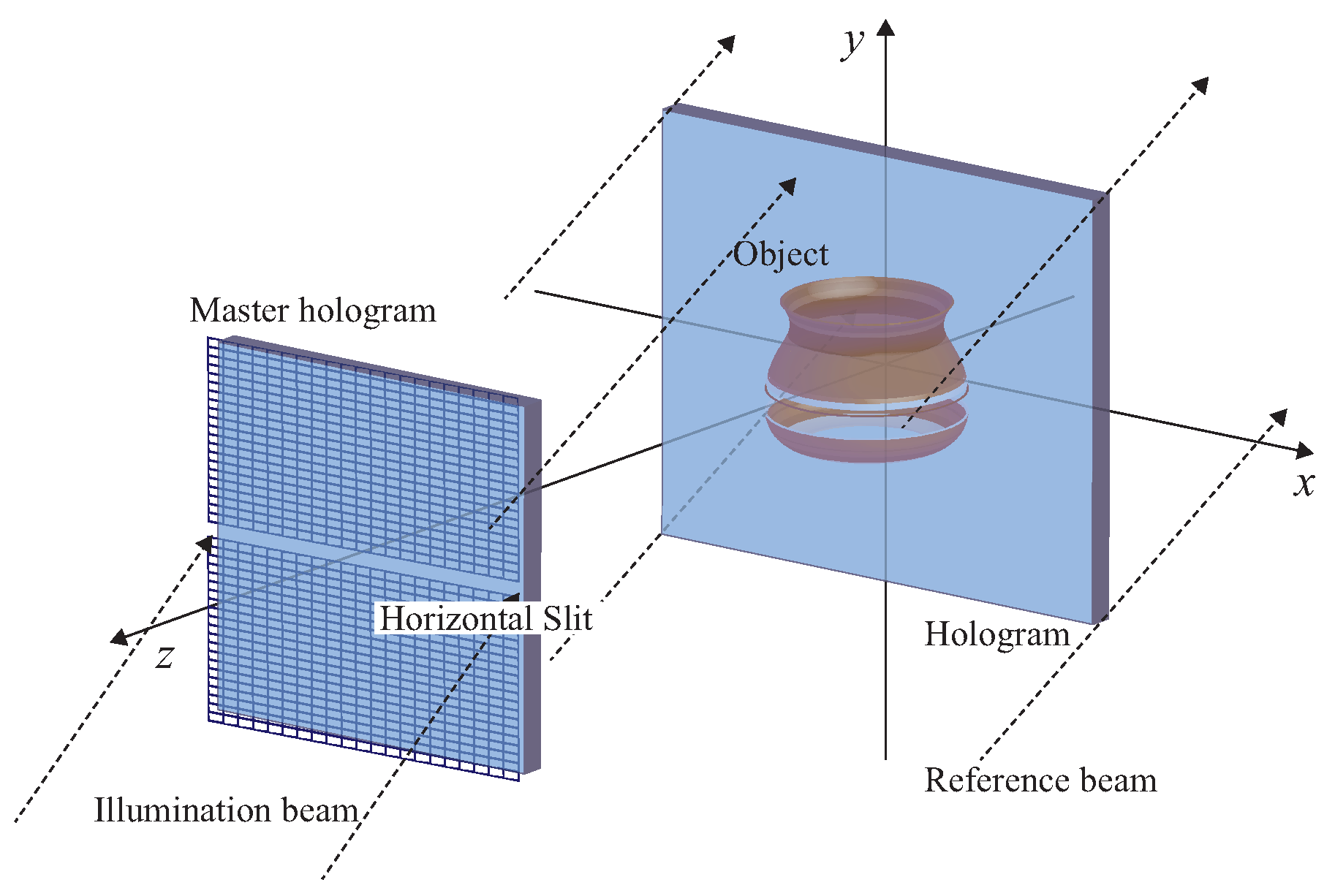
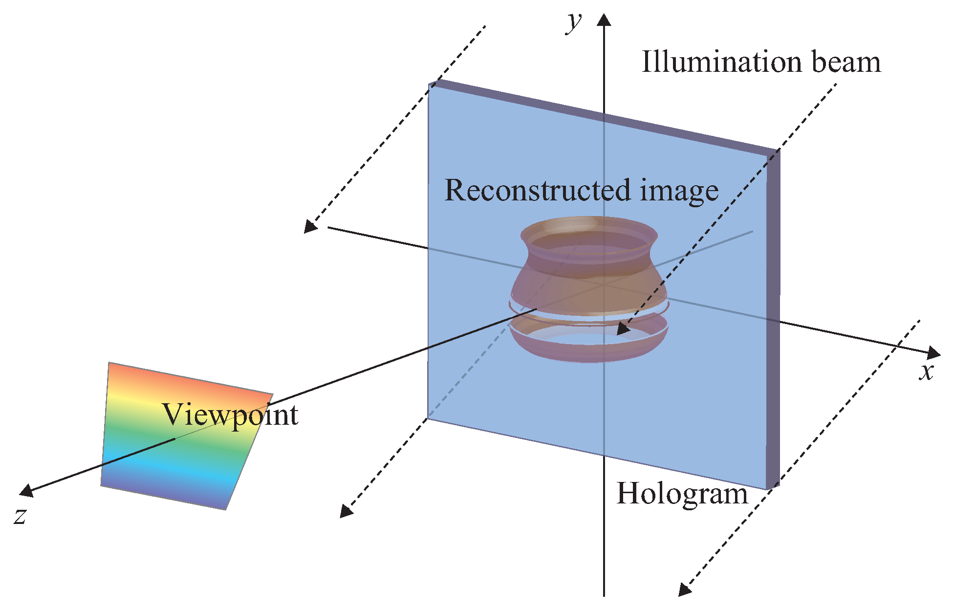
Figure 1 shows the schematic image of the rainbow hologram recording. The viewing area of the reconstructed image from the master hologram is limited by the horizontal slit and recorded as a transfer hologram. Figure 2 shows the reconstruction of the rainbow hologram with white light. The observer can see the monochromatic image from the same position of the horizontal slit. If the observer changes the viewing position on the vertical direction, the color of the reconstructed image also changes. The full-color image can be obtained with three slits corresponding to red, green and blue.
3. Computer-Generated Rainbow Hologram
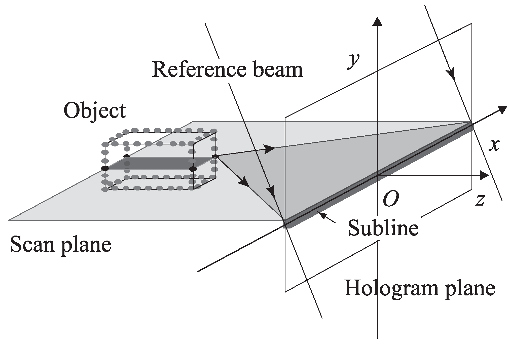
The calculation algorithm of CGRH had been proposed in [10]. Therefore, this section elucidates the gist of the proposed method. The calculation flow can be divided into two steps. In the first step, the 1-D complex amplitude named the sub-line is calculated from sliced object data. Figure 3 shows the calculation geometry of the sub-line. Since the reconstructed image of CGRH only has horizontal parallax, one sub-line should be formed by a single horizontal slice of the object data. The object data are supposed as a collection to the self-illuminated points and can be divided by the position of each point.
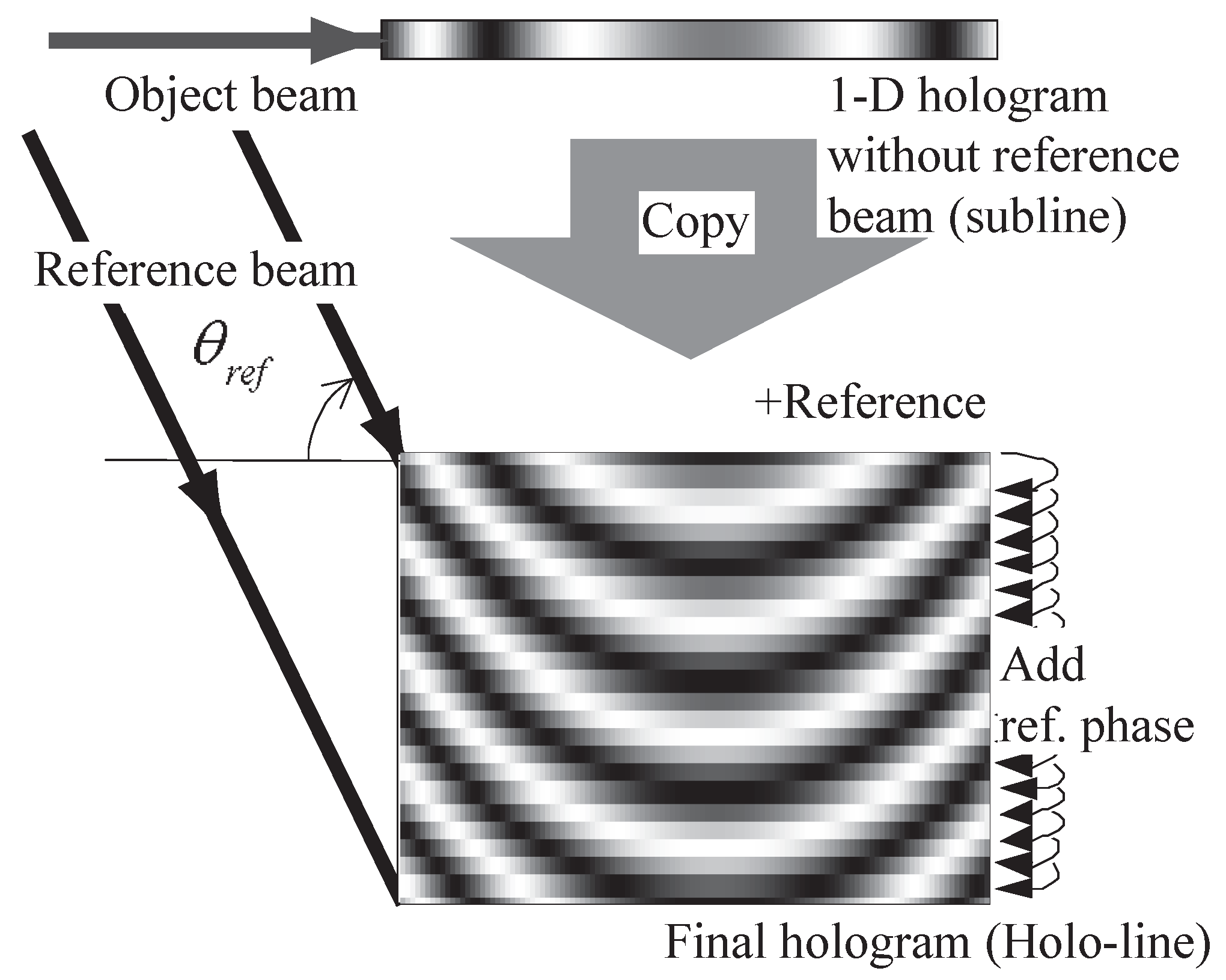
In the second step, we add an off-axis reference, which has a vertical incident angle, to the sub-line. Figure 4 shows the second step of CGRH computation. The 1-D hologram (sub-line) does not have vertical diffracted light. Therefore, the proposed calculation used a reference beam, which only changes the phase on the vertical direction, and part of fringe pattern named the holo-line was calculated. Since the proposed calculation uses the same sub-line in each holo-line, only 1-D object beam calculation is required.
When the calculated CGRH is reconstructed, a cylindrical lens is required to converge the diffracted light to the viewing position. However, this is an undesirable reconstruction when using the lens. Therefore, we added the lens effect to the reference light. This change provides the wavelength selection of the rainbow hologram, and diffracted light by the entire calculated fringe pattern is observed at the same position.
3.1. Calculation of the Fringe Pattern
Computation of the holo-line follows the interference computation between the wavefront of the object beam and the wavefront of the reference beam. The intensity pattern on the hologram plane is described as:
where is the complex amplitude of the object beam on each horizontal slice plane and is the complex amplitude of the reference beam. Since the reference beam of the rainbow hologram is usually a collimated beam, R of Equation (1) only changes in the y direction.
The location of the i-th object point is specified as (, , ). Each point has a real-valued amplitude and a relative phase . The object light of a single sub-line is defined as:
where N is the number of object points for the single sub-line and is the distance between the i-th object point and the point (x) on the hologram. The wavenumber is defined as , where is the free space wavelength of the light. The rainbow hologram displays a 3D image on or close to the hologram plane. The object point that is close to the hologram plane makes a high intensity fringe pattern according to Equation (2). Therefore, Equation (2) is changed into the following equation, which can avoid divergence.
where is a positive constant value.
The complex amplitude is determined by:
where is the vertical incident angle of the illumination beam and is the phase component of the reconstructed beam.
The intensity pattern of Equation (1) becomes:
where and take the real and imaginary part of the complex number , respectively. The first and second term are the DC term, which does not contribute to the reconstructed image. For the calculation of CGRH, the only the third and fourth term are calculated.
To converge the diffracted light to the horizontal slit, the phase component of the reference beam in Equation (6) is changed into the following equation.
where is the convergence angle to the horizontal slit and is the distance between the hologram plane and the viewpoint.
3.2. Calculation Area
The maximum diffraction angle of the CGH depends on the pixel pitch of output device. In this paper, we used a fringe printer, which can output a 0.35-m pixel pitch CGH for the output device. Since the object point that is close to the hologram requires a fine pixel pitch, the calculation area on the hologram plane should be limited by the coordinate of the object point according to the following equation.
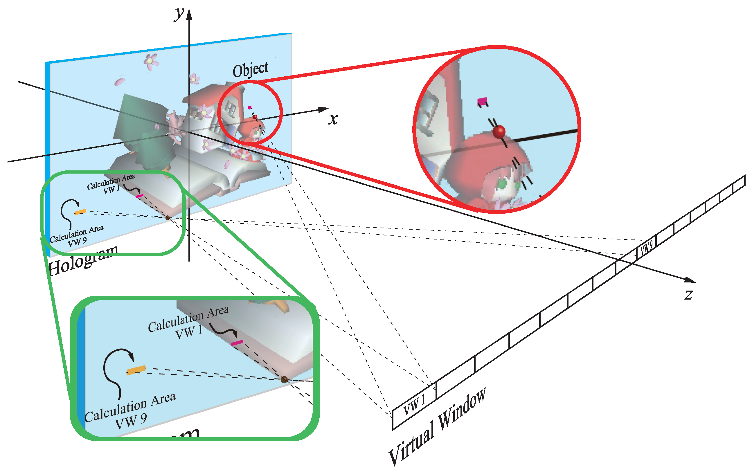
where d is the pixel pitch of the CGH and and are the incident angles of the object beam and the reference beam, respectively. In the actual calculation, we employed the virtual window (as shown in Figure 5), which only passes through the object light, satisfying Equation (10).
4. Point Cloud Creation
The object to be recorded is approximated as a collection of self-illuminated points. Each point has coordinates, a phase component and a real-valued amplitude of R, G, B. Since CG data are usually used as the object, we have to convert CG data to the point cloud data [7].
For the creation of the point cloud from CG data, the OpenGL library is employed as the 3D-API [12]. By using a color buffer and a z-buffer, which are calculated by OpenGL, the point cloud is calculated. However, the color buffer of the calculated point cloud is made from a single viewpoint. Therefore, when the viewer changes position, the absence of the hidden surface’s data causes a problem: hole and overlap. In order to solve this problem, we employed multi-view rendering, which makes multiple point cloud data from several viewpoints. Accordingly, the reconstructed image shows the correct occlusion in every viewpoint.
4.1. Shift Point Data
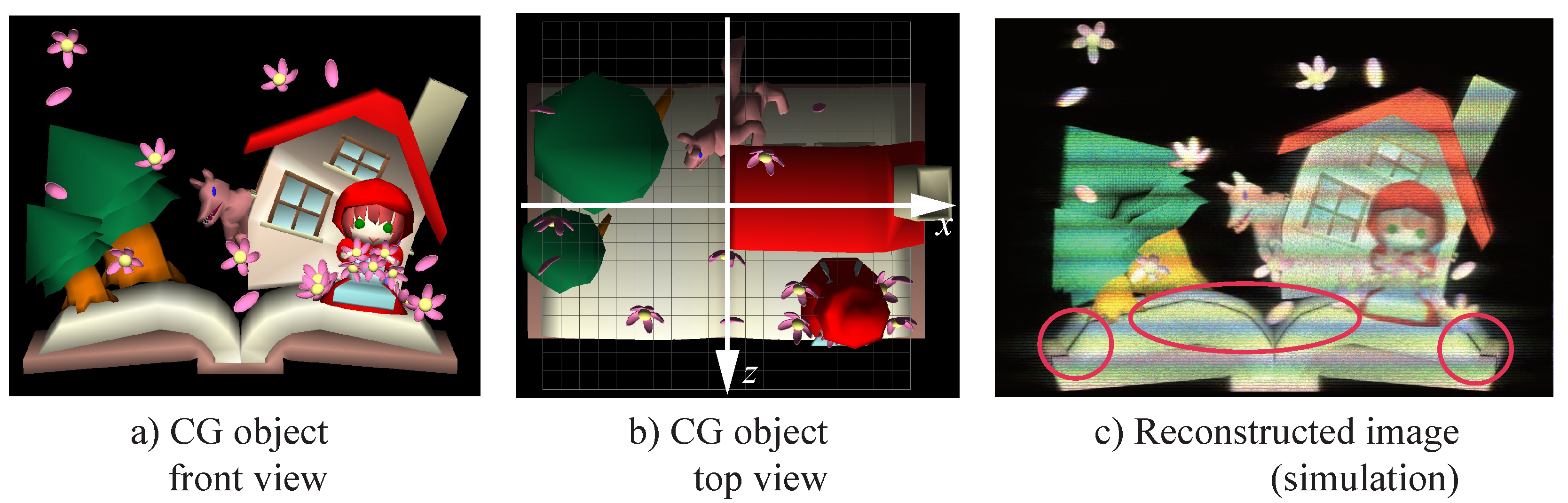
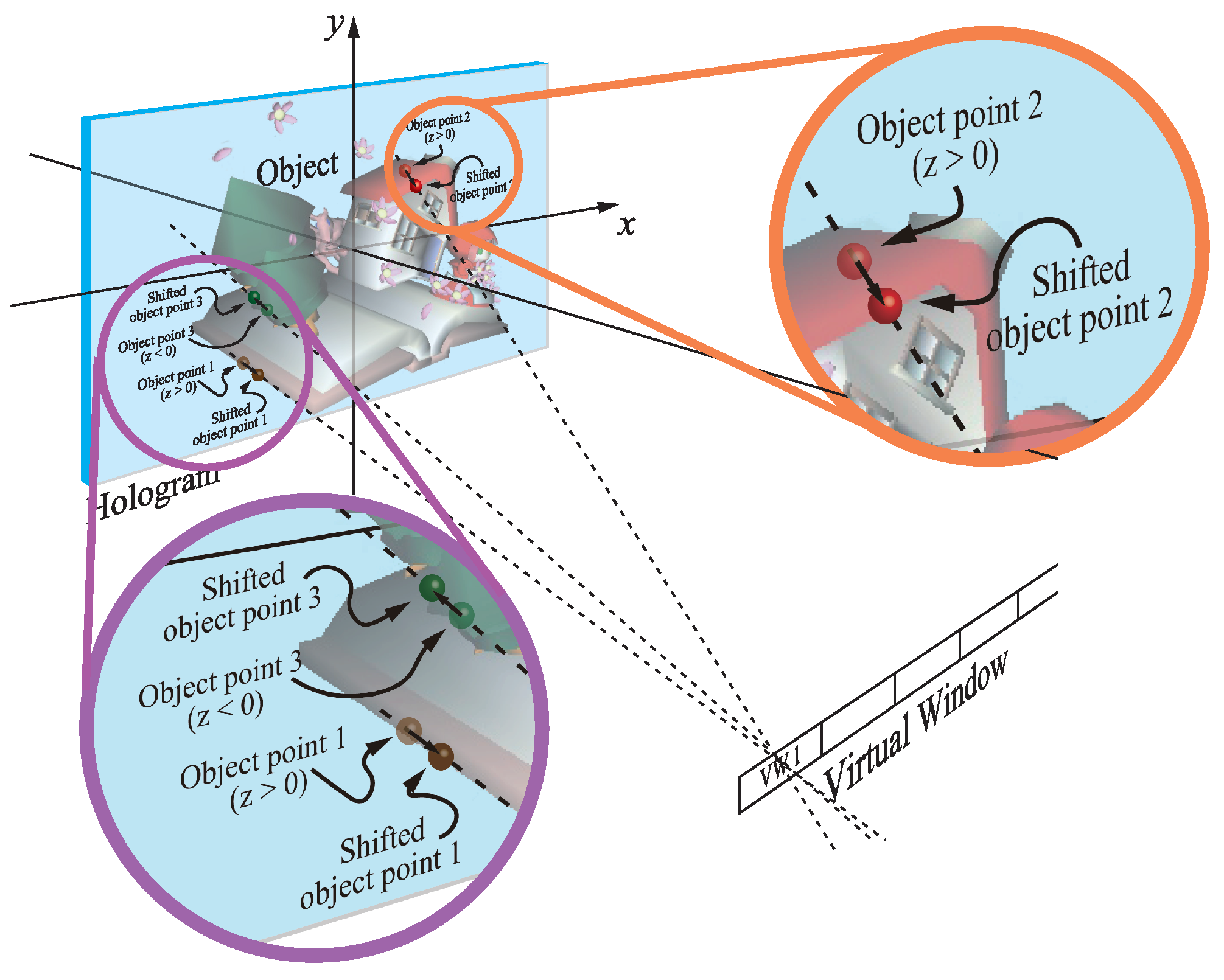
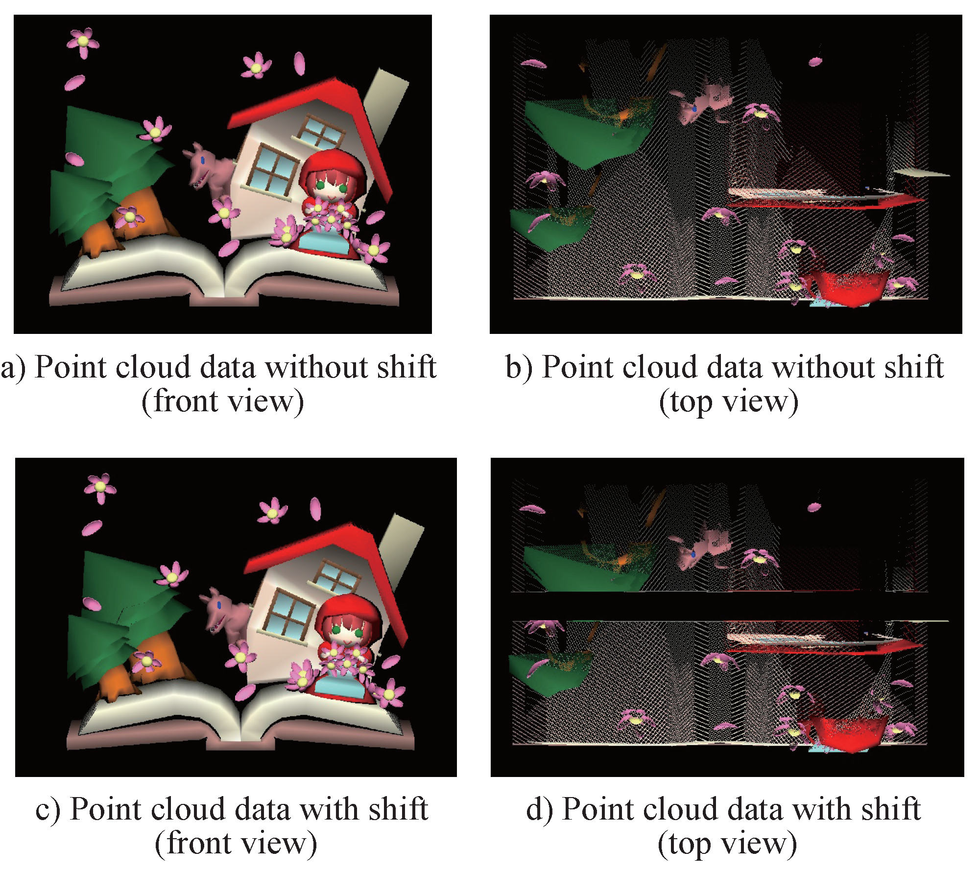
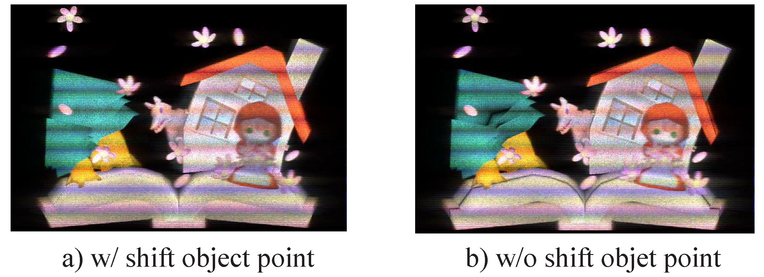
Since the object point that is close to the hologram plane is calculated by Equation (4) to avoid divergence, the intensity of the object beam becomes weak, and the reconstructed image has dark bands on the hologram plane, as shown in Figure 6c. Figure 6a is a CG object used in this research, and the CG object is placed as shown in Figure 6b; the horizontal white arrow shows the hologram plane. Therefore, the object points that are close by less than a certain distance from the hologram plane need to be shifted a bit far from the hologram plane, as shown in Figure 7. Figure 8 shows the original point cloud data and the shifted point cloud data. As is evident from Figure 8, the shifted point cloud data seem almost the same as the original data when the observer sees from front.
4.2. Reallocation of the Point Cloud
According to the performance improvement of the output device, the resolution of CGH becomes very high (over 50 Gpixels). It is difficult to calculate the whole fringe pattern of CGRH at the same time by a general PC. In the calculation of CGRH, each holo-line is independent, as described in Reference [10]. If the object points are only divided with the vertical coordinate, the reconstructed image has distortion. When the hologram is reconstructed, the observer sees diffraction light from the point of the hologram plane, which has to be linearly aligned with the viewpoint and object point. Therefore, the object points are divided with the straight line connecting the viewpoint with the each edge of the holo-line, as shown in Figure 9.
5. Normalization of the Fringe Pattern
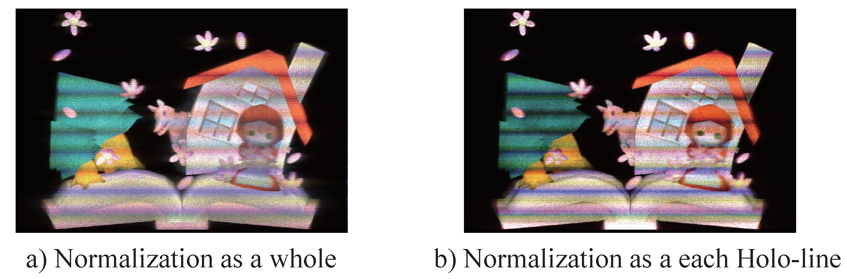
The calculated fringe pattern should be normalized by the entire fringe pattern. Otherwise, each segment reconstructs the difference in the contrast of the image. Especially since the horizontal block of CGRH is calculated for different numbers of object points, the difference in the contrast of the image is very large. In this research, the calculated fringe pattern is stored as the floating-point number and normalized by a range of 3 after the calculation of the whole fringe pattern [13]. This is the standard deviation calculated from the intensity of the fringe pattern.
6. Results
6.1. Fringe Printer
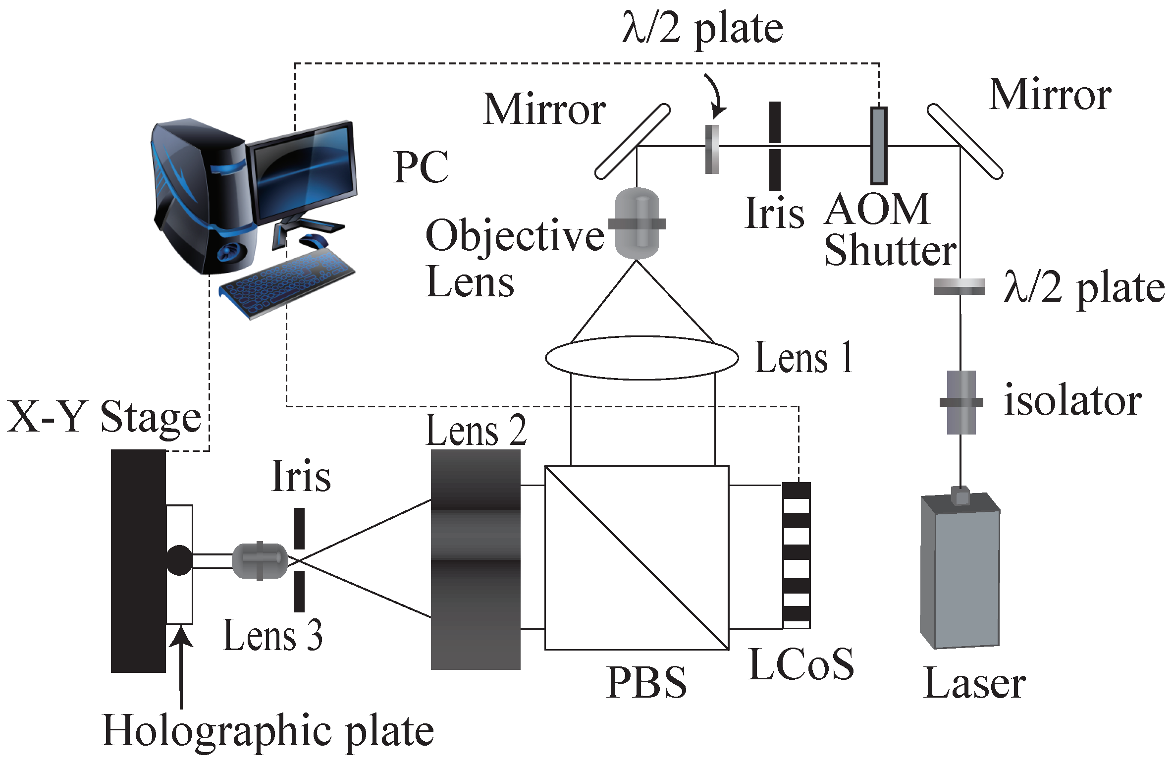
Figure 10 shows the schematic image of the fringe printer. The fringe printer consists of a laser, an X-Y translation stage, liquid crystal on silicon (LCoS) as the spatial light modulator and optical parts. A fractional part of the entire holographic fringe is displayed on the LCoS, and its demagnified image is recorded on a holographic plate. Then, the plate is translated by the X-Y stage to expose the next segment of the fringe. Table 1 shows the fringe printer’s parameter. Holographic material VRP-M, which is manufactured by Slavich, is used as the holographic recording material.VRP-M is a silver halide material.After development, VRP-M is bleached to improve the diffraction efficiency.
6.2. Reconstructed Images
Table 2 shows the parameter of CGRH. For the full-color reconstruction, we calculate three fringe patterns, which use different wavelengths, as shown in Table 2, from point cloud data. The calculated fringe patterns are synthesized to an 8-bit gray-scale bitmap pattern. We used a Windows 10 64-bit PC, which has Intel Core i7 7700 K CPU and 32 GB memory. By using the proposed method, an over 50-Gpixel CGRH was calculated with uniform contrast. Since the normalization had to be calculated after the entire fringe pattern calculation, the previous method only created about a quarter size of the memory size, because the fringe pattern is calculated as a float value. After the point cloud data creation, it took 14.5 min to process and to prepare the fringe calculation such as the shift of object points, the addition of the calculation area and sorting the point cloud data for each holo-line. The computation time of the fringe pattern was approximately 50 min. Figure 11 shows the reconstructed images from several viewpoints. A white LED light, called HOLOLIGHT [14], was used as the illumination light. HOLOLIGHT can easily make light that is close to the collimated light. Reconstructed images show good color reproduction compared with the original CG in the horizontal direction. In the change of the viewpoint in vertical direction, the color spectrum changes from red to blue, as shown in Figure 11a,e.
Figure 12 shows the numerical reconstruction for with and without shift object points, which are placed on or close to the hologram plane. To apply shift object data, the dark bands of Figure 12b are solved in Figure 12a. Figure 13 shows the reconstruction from the different normalizations. To change the normalization of each holo-line to the entire hologram, the contrast of the reconstructed image became uniform. These numerical simulations employed the algorithm of [15].
7. Conclusions
In this research, we have calculated and output an over 50-Gpixel CGRH that reconstructs a full-color 3D image. The reconstructed images shows good color reproduction. For the calculation of the large CGRH, we proposed split calculation for each holo-line. To apply this calculation model, several object data, which were created from different viewpoints, were managed. In addition, to employ the shift object data and the normalization as a whole, the output CGRH provides good reconstructed images.
Author Contributions
Conceptualization, T.Y. and H.Y.; methodology, T.Y. and H.Y.; software, T.Y.; validation, T.Y. and H.Y.; formal analysis, T.Y. and H.Y.; investigation, T.Y.; resources, T.Y. and H.Y.; data curation, T.Y.; writing—original draft preparation, T.Y.; writing—review and editing, T.Y. and H.Y.; visualization, T.Y.; supervision, T.Y.; project administration, T.Y.
Funding
This research received no external funding.
Acknowledgments
The authors would like to thank Yayoi Nakaguchi for CG data creation.
Conflicts of Interest
The authors declare no conflict of interest.
Abbreviations
The following abbreviations are used in this manuscript:
| CGH | Computer-generated hologram |
| CGRH | Computer-generated rainbow hologram |
| SLM | Spatial light modulator |
| PBS | Polarized beam splitter |
| LCoS | Liquid crystal on silicon |
References
- Hamano, T.; Yoshikawa, H. Image-type CGH by means of e-beam printing. Proc. SPIE 1998, 3293, 2–14. [Google Scholar]
- Nishi, H.; Matsushima, K. Rendering of specular curved objects in polygon-based computer holography. Appl. Opt. 2017, 56, F37–F44. [Google Scholar] [CrossRef] [PubMed]
- Sakamoto, Y.; Morishima, M.; Usui, A. Computer-generated holograms on a CD-R disk. Proc. SPIE 2004, 5290, 42–49. [Google Scholar]
- Yoshikawa, H.; Yamaguchi, T.; Iwamoto, T. Improvement on printed image fidelity of fringe printer for computer-generated holograms. In Proceedings of the 11th International Symposium on Display Holography, Aveiro, Portugal, 25–29 June 2018. [Google Scholar]
- Yamaguchi, T.; Matuoka, M.; Fujii, T.; Yoshikawa, H. Development of fringe printer and its practical applications. In Proceedings of the 8th International Symposium on Display Holography, Shenzhen, China, 13–17 July 2009; pp. 572–582. [Google Scholar]
- Yamaguchia, T.; Ozawa, H.; Yoshikawa, H. Computer-generated Alcove hologram to display foating image with wide viewing angle. Proc. SPIE 2011, 7959, 795719. [Google Scholar]
- Waters, J.P. Holographic image synthesis utilizing theoretical methods. Appl. Phys. Lett. 1966, 9, 405–407. [Google Scholar] [CrossRef]
- Lucente, M. Interactive Computation of Holograms Using a Look-up Table. J. Electr. Imaging 1993, 2, 28–34. [Google Scholar] [CrossRef]
- Matsushima, K.; Nakahara, S. Extremely high-definition full-parallax computer-generated hologram created by the polygon-based method. Appl. Opt. 2009, 48, H54–H63. [Google Scholar] [CrossRef] [PubMed]
- Yoshikawa, H.; Taniguchi, H. Computer Generated Rainbow Holograms. Opt. Rev. 1999, 6, 118–123. [Google Scholar] [CrossRef]
- Benton, S.A. Hologram Reconstructions with Extended Incoherent Sources. J. Opt. Soc. Am. 1969, 59, 1545A. [Google Scholar]
- Fujii, T.; Yoshikawa, H. OpenGL-based Rendering of Computer-Generated Rainbow Hologram. In Proceedings of the Nicograph International, Pattaya, Thailand, 30–31 May 2008. [Google Scholar]
- Nakaguchi, Y.; Yamaguchi, T.; Yoshikawa, H. Image quality improvement of large size image type computer-generated hologram. In Proceedings of the 2012 International Workshop on Advanced Image Technology, Ho Chi Minh City, Vietnam, 9–10 January 2012; pp. 572–575. [Google Scholar]
- Nemoto, A.; Ikeda, T. A high-directional LED system to form holographic light patterns. SPIE Newsroom 2016. [Google Scholar] [CrossRef]
- Yoshikawa, H.; Yamaguchi, T.; Fujita, H. Computer Simulation of Reconstructed Image from Rainbow Hologram. In Proceedings of the OSA Technical Digest (CD) (Optical Society of America, Vancouver, BC, Canada, 18–20 June 2007. [Google Scholar]
Figure 1.
Recording of the rainbow hologram.

Figure 2.
Reconstruction of the rainbow hologram by white light.

Figure 3.
Calculation geometry for the sub-line.

Figure 4.
Two steps to calculate the holo-line of a computer-generated rainbow hologram.

Figure 5.
Addition of the calculation area by the virtual window.

Figure 6.
CG object and simulated image including the dark bands problem.

Figure 7.
Shift object points in the direction of the virtual window.

Figure 8.
Point cloud data with and without shift.

Figure 9.
Split object data for each horizontal calculation block.

Figure 10.
Schematic of the fringe printing system.

Figure 11.
Reconstructed images from several viewpoints.

Figure 12.
Comparison of with and without shift object data (numerical reconstruction).

Figure 13.
Comparison of the normalizations (numerical reconstruction).


Table 1.
Parameters of the improved fringe printer.
| Fringe Printer | Value |
| Moving Area (mm) | 200 × 200 |
| Focal Length (L2) (mm) | 200 |
| Focal Length (L3) (mm) | 10 |
| Demagnification Rate | 1/20 |
| Wavelength (laser) (nm) | 473 |
| LCoS | Value |
| Resolution (pixel) | 1920 × 1080 |
| Pitch (m) | 7.0 |
| Gray-scale Level (bit) | 8 |
Table 2.
Parameter of the hologram.
| Parameter of the Hologram | Value |
|---|---|
| Resolution (pixels) | 288,080 × 194,560 |
| Size (mm) | 101 × 68.1 |
| Pitch (m) | 0.35 |
| Wavelength (R, G, B) (nm) | 633, 532, 473 |
| Sub-line resolution (pixels) | 512 |
| Number of holo-lines | 380 |
| Average number of object points | approximately 335,000 |
© 2018 by the authors. Licensee MDPI, Basel, Switzerland. This article is an open access article distributed under the terms and conditions of the Creative Commons Attribution (CC BY) license (http://creativecommons.org/licenses/by/4.0/).
Share and Cite
MDPI and ACS Style
Yamaguchi, T.; Yoshikawa, H. High Resolution Computer-Generated Rainbow Hologram. Appl. Sci. 2018, 8, 1955. https://doi.org/10.3390/app8101955
AMA Style
Yamaguchi T, Yoshikawa H. High Resolution Computer-Generated Rainbow Hologram. Applied Sciences. 2018; 8(10):1955. https://doi.org/10.3390/app8101955
Chicago/Turabian StyleYamaguchi, Takeshi, and Hiroshi Yoshikawa. 2018. "High Resolution Computer-Generated Rainbow Hologram" Applied Sciences 8, no. 10: 1955. https://doi.org/10.3390/app8101955
Note that from the first issue of 2016, this journal uses article numbers instead of page numbers. See further details here.