1. Introduction
Wireless power transfer (WPT) via magnetic resonance coupling has extensive application prospects in people’s daily lives, such as electrical vehicle charging, home application, portable electronic devices, and robotic applications [
1,
2,
3,
4]. The transfer characteristics of special WPT systems and promotion of the practicability have become the major hotspots in the WPT research field. In recent studies, the mid-range WPT system mainly concentrates on four methods: (i) Traditional two-coil system, (ii) four-coil system with/without metamaterials (MMs), (iii) WPT system with relay resonators, and (iv) WPT system via a magneto-inductive wave. These four methods have their unique strengths and weaknesses. Additionally, they were analyzed and contrasted specifically in [
5]. The principle of wireless power transfer based on magnetically coupled resonance is to take advantage of the resonance coupling of high quality factor coils to realize energy exchange in the near field. The energy exchange ratio and transfer loss are determined by the coupling strength and the quality factor of coils. In the mid-range WPT system, the system energy efficiency and transmission distance are important indicators.
In mid-range operation, the transfer distance is usually 50–200 cm [
6]. The magnetic coupling coefficient between the two coils decreases sharply when the transfer distance increases. In recent years, a number of research methods have been adopted to analyze the mid-range WPT system. Duong et al. [
7] presented an effective method using the “matching condition” technology, which is based on adaptively varying the coupling coefficient between the drive (load) coil and transmission (receiver) coil for the impedance matching to achieve maximum efficiency. Zhang et al. [
8] introduced three significant factors in the four-coil structure of resonant WPT and simplified the circuit calculate formula to attain maximum transfer efficiency and output power. Pinuela et al. [
9] manifested that the system de-to-load efficiency based on the two-coil inductive mode can be improved greatly by using a Class-E power amplifier, and the system also employed high Q factor coils operating at about 6 MHz. Reference [
10,
11,
12] employed the physics of the magneto-inductive wave method to explain the behavior of the WPT system with several planar printed resonators in which each capacitive loaded resonator was coupled magnetically to a series of other resonators. The studies in [
13,
14,
15] reported relay resonators applied between the drive loop and load loop to improve the transmission efficiency and increase the transfer distance operating at a high-frequency situation. The works in [
16,
17,
18,
19,
20,
21,
22] showed that the negative permeability MMs enhanced the system efficiency and transmission distance due to its abilities of controlling the magnetic field and evanescent wave amplification. However, most research with the MMs has used the scattering parameter (mainly the S
21 parameter) to describe the transfer efficiency by the network analyzer experimentally, rather than practical system energy efficiency, let alone using the Class-E power amplifier as a high frequency source to drive the whole WPT system with the MMs.
In this paper, we adopt the four-coil WPT system based on magnetically coupled resonance with the MMs in the near field. We firstly extended original research of the four-coil WPT system to elucidate a number of crucial system concepts, including the maximum power efficiency and the optimal load. Then, a single-layer square thin unit cell of loaded spiral resonators was designed. Accordingly, these units were assembled in a 5 × 5 slab periodically to achieve a negative magnetic permeability. Furthermore, the tuning scheme was proposed to contribute to the transfer property. In addition, the Class-E power amplifier was employed as the inverter circuit topology to adapt to the highly operating frequency of 2.80 MHz. By applying this technology, the system energy efficiency could be improved by 4.26% and 9.13% at distances of 100 cm and 200 cm, respectively. The proposed system is significant as a power supply for electric applications in relatively far distances, such as a mobile phone and tablet PC. In particular, this technology can make the power grid much smarter by supplying high voltage power pole tower on-line monitoring terminal devices.
2. Proposed WPT System with the MMs
It is well known that the four-coil WPT system based on magnetic resonance coupling consists of the drive coil, the transmitting coil (
Tx), the receiving coil (
Rx), and the load coil. Normally, the distance between the drive coil (load coil) and the
Tx (
Rx) coil is relatively close, so the magnetic coupling is relatively strong. Nevertheless, the
Tx coil is far from the
Rx coil and the coupling coefficient is low conversely.
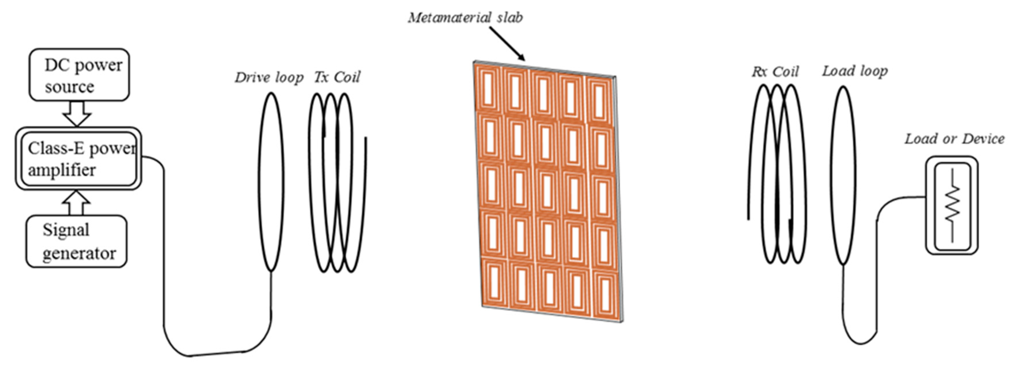
Figure 1 presents a diagram of the four-coil WPT system with the MMs. The adjustable DC power source supplies the Class-E amplifier, and the signal generator can emit a high frequency Pulse Width Modulation (PWM) square wave. The Class-E amplifier is designed to amplify the power of a high frequency signal to meet the requirement of transmitting power. The MMs is placed between the
Tx and
Rx coil, the position of which is varied constantly and the optimal position of the MMs needs to be analyzed. The load resistance is the link to the load loop.
2.1. Theoretical Analysis of the Four-Coil WPT System
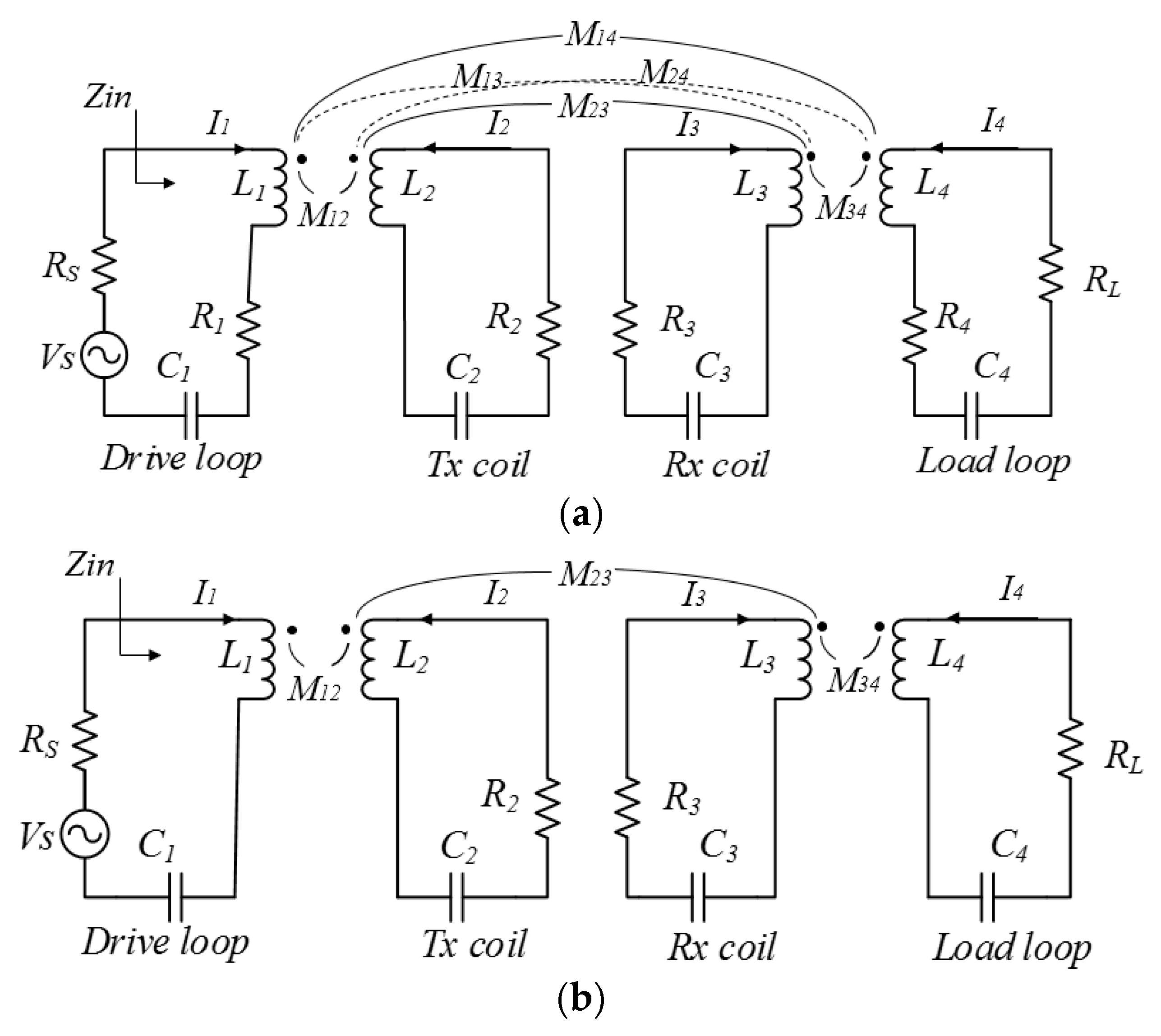
Figure 2 shows the equivalent circuit diagrams of the four-coil WPT system. All the parameters are considered in the complete model. As a contrast, the equivalent model can be simplified to ignore the less influential quantities. The internal resistance of the power source and the load equivalent resistance are
RS and
RL, respectively. The signal source is denoted by Vs. The distance of the
Tx coil and
Rx coil is defined as the transfer distance in the four-coil WPT system. The electrical parameters of each coil are denoted by
RiLiCi (
i,
j = 1, 2, 3, 4).
Mij is the mutual inductance of two adjacent coils, and the cross coupling parameters are negligible (
M13 =
M24 =
M14 = 0). Compared with the
Rs and
RL, the coil equivalent resistance of the drive loop and the load loop are so tiny so are neglected. In addition, the four coils have same operating resonance frequency. The simplified circular model is illustrated in
Figure 2b.
When the proposed four coils work at same resonant frequency of 2.80 MHz, according to the Kirchhoff voltage law (KVL) and the mutual coupling theories, the voltage and current in each coil can be illustrated as follows:
Similarly, the input impedance,
Zin, is a very significant parameter for the design of Class-E, and it can be expressed as:
Solving (1) and (2), the
Zin can be derived [
7], which is:
where
Qi is the quality factor of the
ith coil.
Q1 is equal to
Q4 and
Q2 is the same as the
Q3 due to the symmetry of the proposed system.
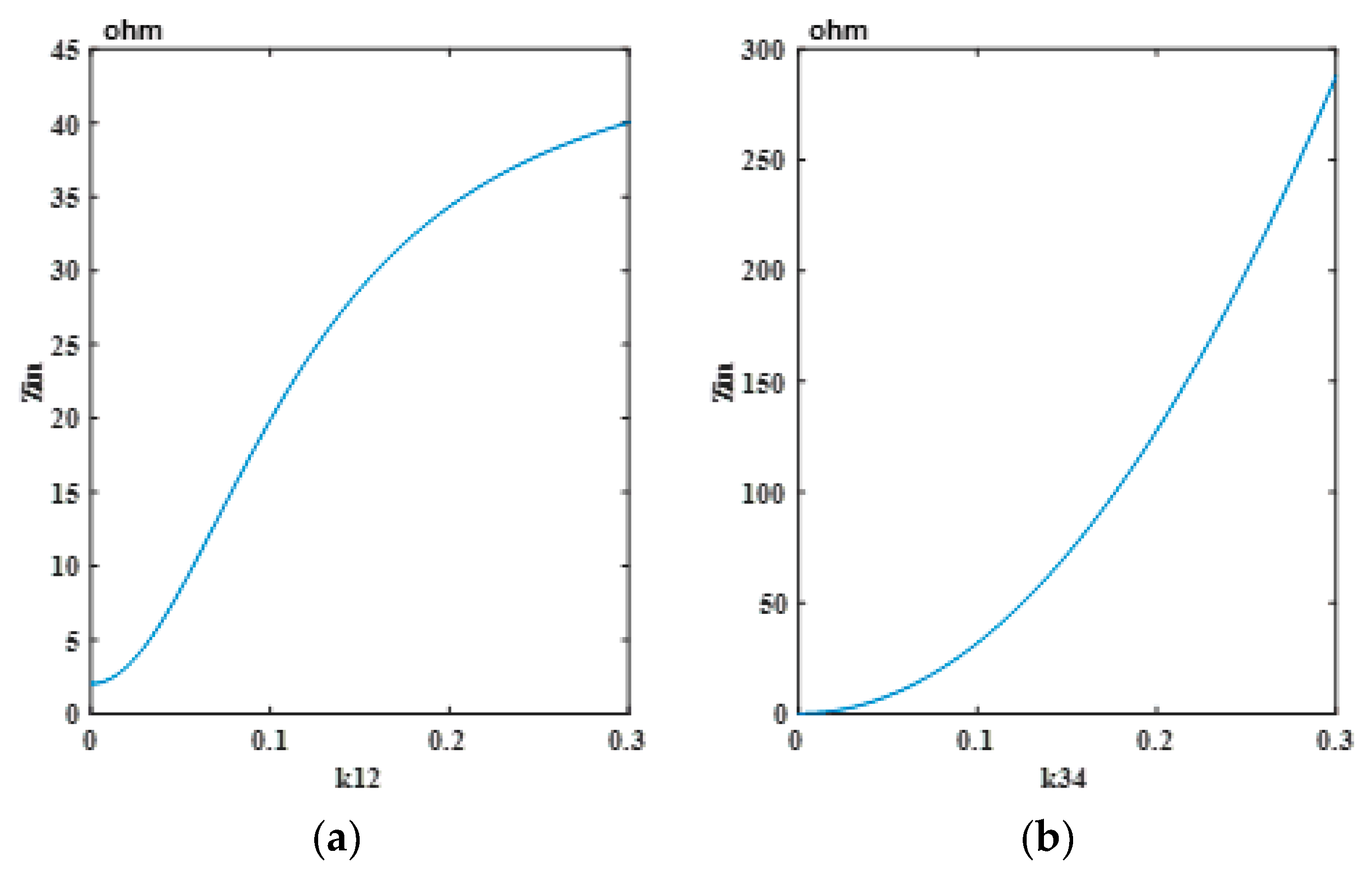
k12,
k23, and
k34 are the coupling coefficients of the drive loop and the
Tx coil, the
Tx coil and the
Rx coil, and the load loop and the
Rx coil, respectively. When the distance between the coils changes, the coupling coefficient varies correspondingly, and eventually the
Zin changes, as shown in the
Figure 3. It can be seen that as
k12 and
k34 increase, the efficiency also is improved.
For a traditional two-coil WPT system, the secondary coil can be reflected as the pure resistance when two coils are in resonance. By adjusting the load resistance value, the system can achieve the maximum efficiency output, namely, there is an optimal load in the system. The optimal load can be expressed as [
23]:
in which
k is the coupling coefficient,
Qi is the quality factor of the
ith coil, and
R2 is the resistance of the secondary coil. Similarly, the four-coil WPT system can be equivalent to the traditional two-coil resonator. The drive loop can be reflected to the
Tx coil and the load loop can be reflected in the
Rx coil, as shown in
Figure 4.
Rseqt,
Vseqt, and
RLeqt is the equivalent resistance, voltage supply, and the load resistance, respectively.
According to the two-coil system optimal load analysis, the optimal reflected resistance,
RLeqt, from the load loop to the
Rx coil in the four-coil WPT system can be derived as:
From the above formula, to adjust the coupling coefficient between the load loop and the Rx coil, namely, to change the distance between the load loop and the Rx coil, an optimal load and improvement of the transfer efficiency of the system can be achieved.
In the four-coil WPT system, the system transfer efficiency can be denoted by the power distribution among the equivalent reflected resistances in each coil. The total efficiency is equal to the product of the equivalent resistance ratios. Thus, when four coils are tuning to the resonance frequency, the efficiency is calculated as:
The efficiency can be expressed in another form [
24]:
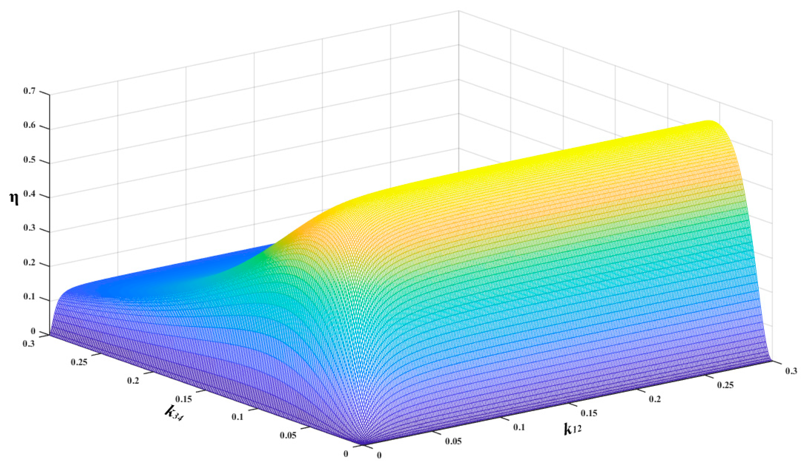
Figure 5 shows the system efficiency, η, as a function of
k12 and
k34. It can be seen that
k34 has a greater effect on the efficiency than
k12. Generally, when the transfer distance between the
Tx coil and
Rx coil is fixed, the maximum efficiency can be achieved by adjusting the distance between the
Rx coil and the load loop.
In a practical experiment, the distance between the Tx coil and the Rx coil is fixed at some value (k23 is fixed value), and k12 and k34 are varied by adjusting the distance between relevant coils to change the Zin and system efficiency in the meantime. From the optimal load analysis of the four-coil WPT system, the k34 is an important factor to the optimal load. In addition, the k34 has a greater influence than the k12 on the Zin and system efficiency. In general, we fixed the distance between the Tx coil and the Rx coil and varied the distance between the load loop and the Rx coil to achieve the optimal load, and then changed the distance between the drive loop and the Tx coil to attain the needed Zin of the Class-E amplifier.
2.2. Analysis and Design of the MMs
It is generally known that the MMs with negative permeability have the supernatural ability that changes the direction of the magnetic propagation and contributes to distance enhancement and efficiency improvement. Reference [
20,
21,
22] used the numerical models and analytical theory to explain the principle of MM’s focusing property. According to Maxwell equations:
where
w is the plane electromagnetic wave frequency,
k is wave vector, μ is the dielectric permeability, ε is the dielectric constant,
E is the electric field intensity, and
H is the magnetic field intensity. According to the formula,
, when
k,
E, and
H form the left hand system, and the refractive index,
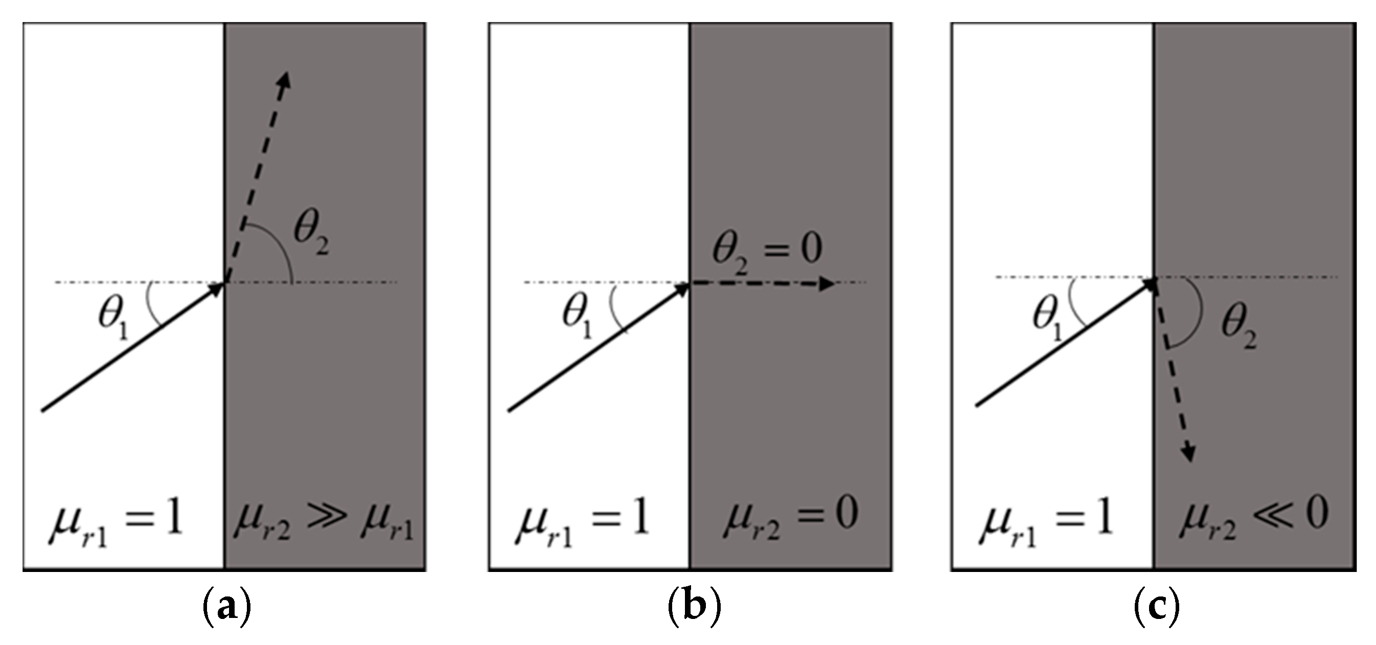
n, is negative. When the electromagnetic wave enters the surface of the medium, according to Fresnel’s law:
θ1 and
θ2 are the angle of incidence and refraction. As shown in
Figure 6, the refraction occurs when electromagnetic waves pass through two dielectric interfaces with opposite chirality.
Figure 6c manifests that the reflected wave and the incident wave are in the same direction when the relative permeability is negative. If the magnetic field can be restrained effectively and controlled artificially to solve the problem of rapid divergence and attenuation of the magnetic field, the transmission distance and efficiency of the magnetic resonance wireless transfer system can be improved effectively [
18].
To achieve the desired MMs slab, the HFSS (High Frequency Simulator Structure) software was adopted to simulate the MM structure. The S-parameter can be obtained and finally converted into the relationship between the relative permeability and frequency [
25,
26,
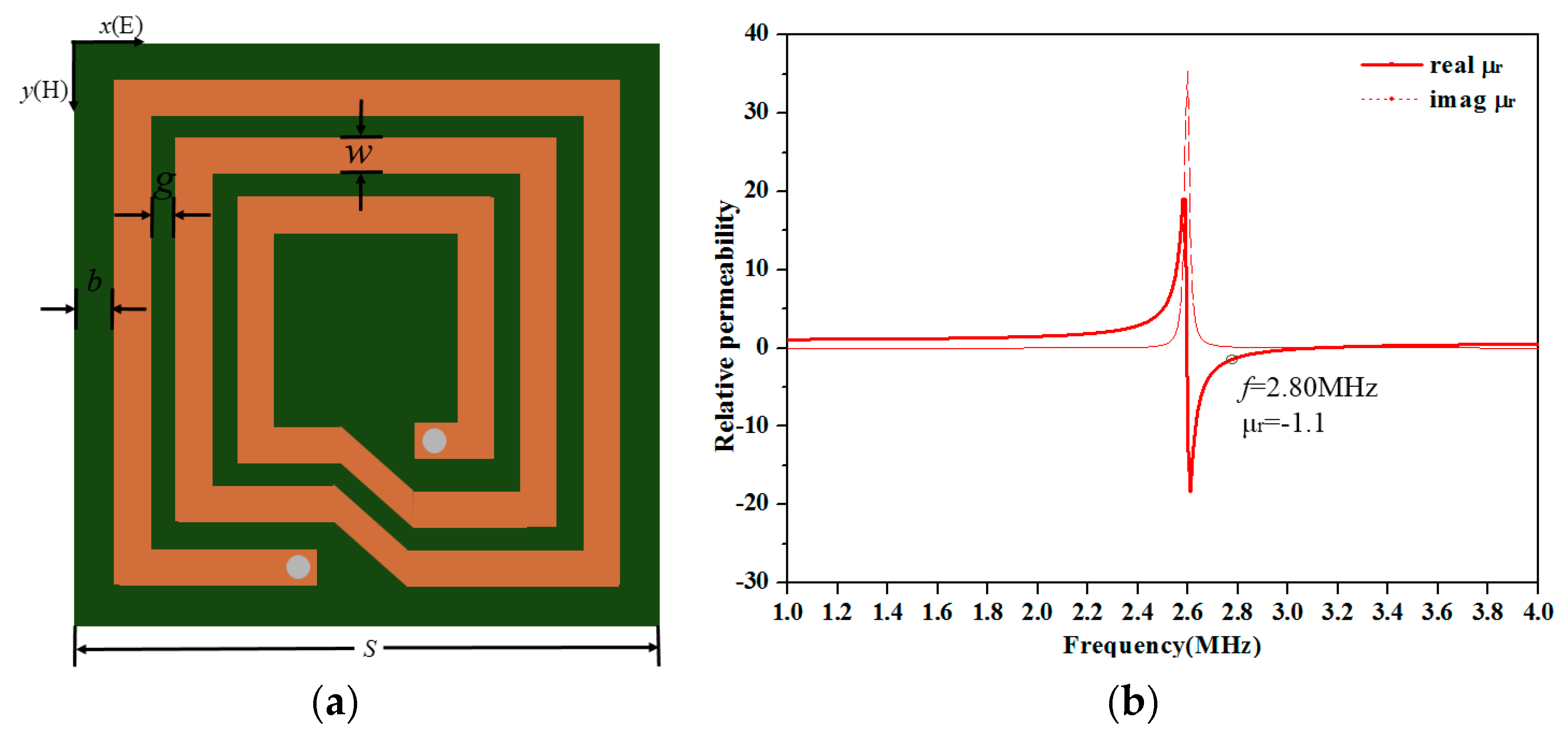
27]. To make the MM unit cell elastic and compact, the proposed MM unit cell was designed to be square with a length of 120 mm and a series capacitance of 2.27 nF was welded on both ends of the copper strip to tune the resonant frequency of the MM unit cell. The structure diagram of the MM unit cell is shown in
Figure 7a. The substrate was made of FR-4 whose relative dielectric constant was εr = 4.4 and the loss tangent was tanδ = 0.025 and its thickness was 2mm. The extracted relative permeability curve depending on the frequency of the MM unit cell is illustrated in
Figure 7b. The structure parameters of the MM unit cell are listed in
Table 1.
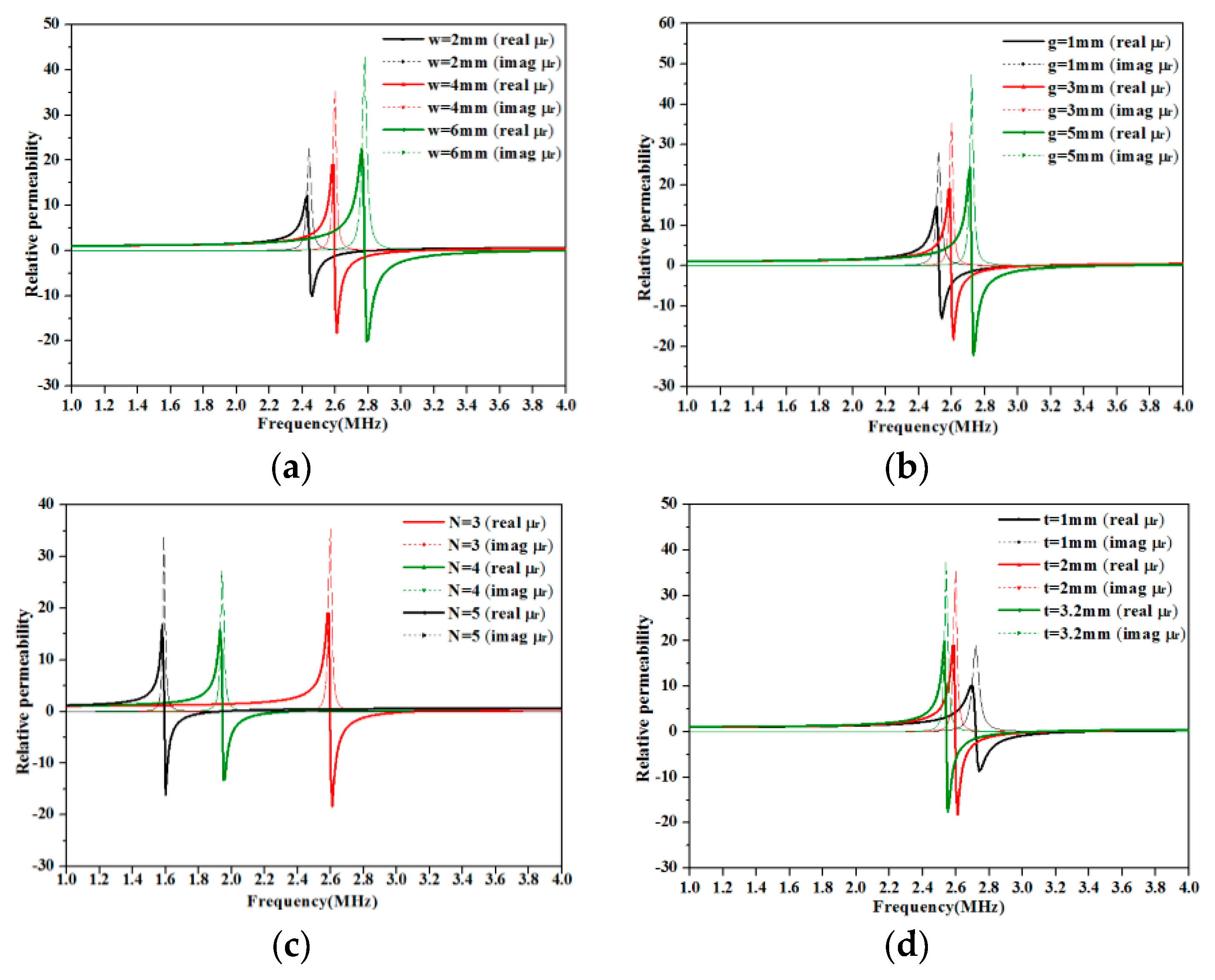
To optimize the MM unit cell design, a variety of parameter structures were compared for resonance frequency control, as shown in
Figure 8. When the width, the interval and the turn of the copper strip, and the thickness of the substrate varied, the resonance frequency of the MM unit cell changed correspondingly. It can be seen that the width and interval had no obvious influence on the resonance frequency, whereas the change of the turn made the resonance frequency deviate largely. The main reason was that the increase of the turn number made the inductance increase more distinct. In addition, the thickness of the substrate had less impact for the resonance frequency. In this paper, the MM unit cell adopting the above structure parameters was a comprehensive consideration of size, flexibility, and firmness in fabrication. To accommodate the coil size, the MMs slab consisted of a 5 × 5 unit cell, and the diameter of the
Tx (
Rx) coil was 500 mm.
3. Fabrication of Class-E Amplifier and Experiment Verification
To verify the previous power transfer efficiency analysis and the effect of MMs, a high-frequency Class-E power drive was designed. The Class-E amplifier has a simple topology and operating frequency up to the MHz level. It is suitable to be used as a high frequency excitation source for the WPT system with the MM. The Class-E amplifier consists of the DC voltage source
VI, RF choke
Lf, shunt capacitance,
C1, Metal-Oxide-Semiconductor Field Effect Transistor (MOSFET),
S, resonant capacitance,
C, and inductor,
L. It can reach the soft switching state with the appropriate parameter of the electrical component [
28,
29,
30]. Furthermore, the RF Class-E topology needs to be chosen to meet the four-coil system property.
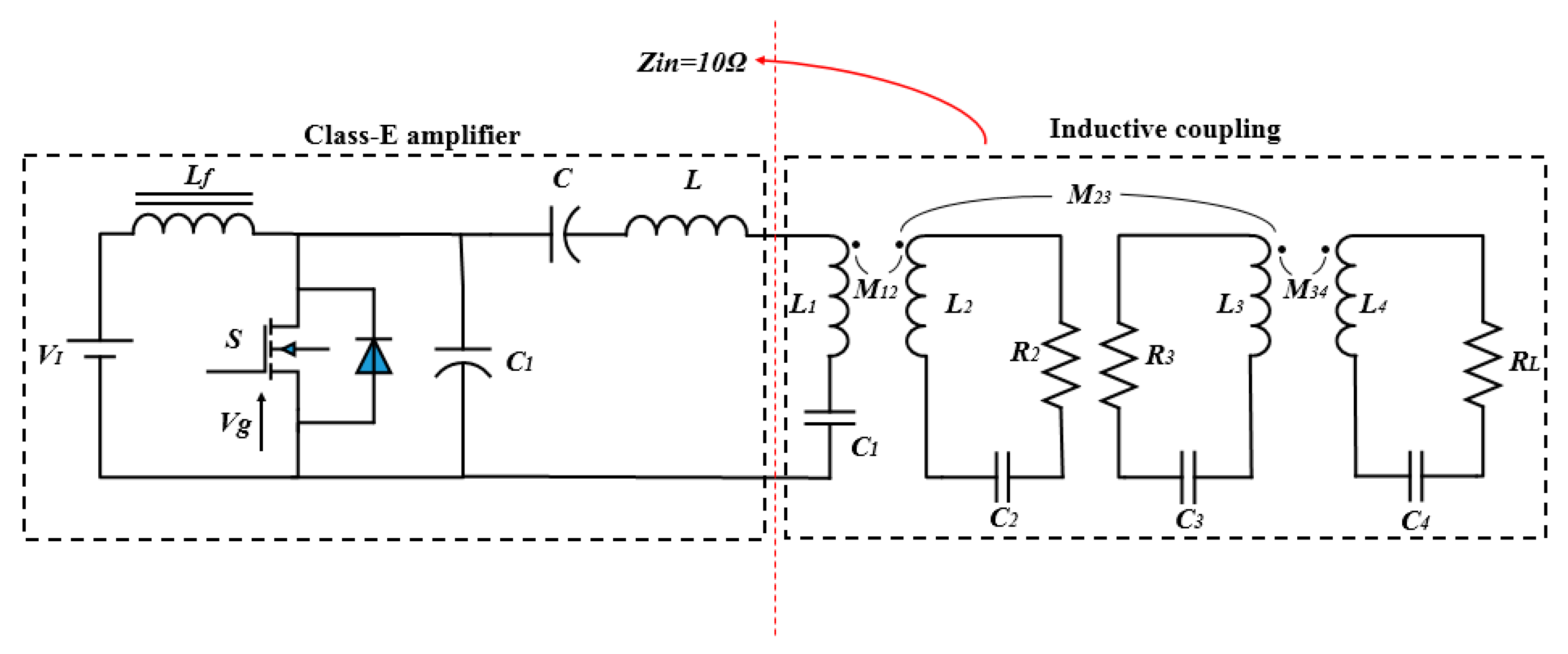
Figure 9 shows the circuit sketch of the WPT system with the Class-E amplifier. We set the equivalent output resistance of the Class-E to 10 Ω, namely, the
Zin needed to be adjusted to 10 Ω by varying the distance between coils. The operating frequency of system was 2.80 MHz. The quality factor was set as 8. The rest of the parameters were calculated by expression (10).
Table 2 lists the parameters of the Class-E amplifier.
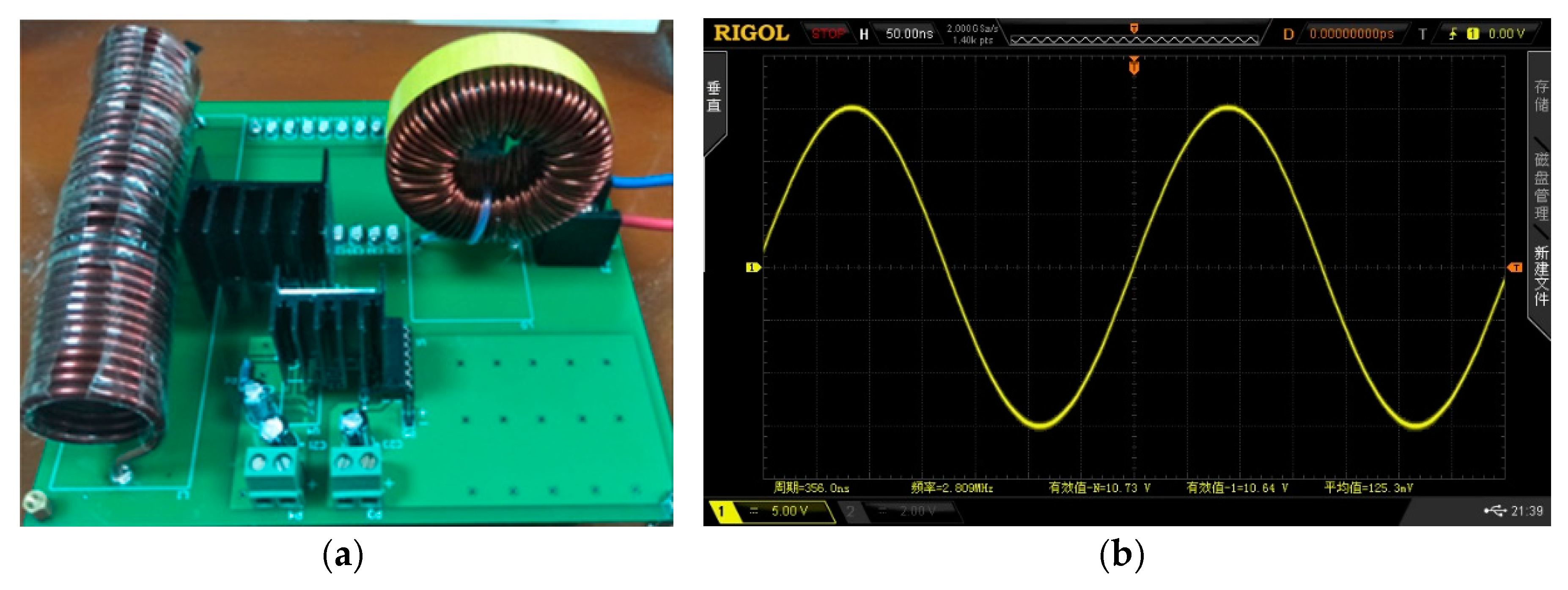
A few megahertz switching frequency and hundreds of watts can be achieved by the using of silicon carbide devices (C2M008012D), and its conduction resistance and parasitic capacitance are very tiny. The driver chip (IXDD614) was employed in this circuit template, as shown in
Figure 10a.
Figure 10b shows that voltage waveform of the test load resistance, the waveform was a sinusoidal wave approximately and its working frequency was 2.80 MHz. The duty ratio of the signal was less than 50%, ensuring that the amplifier operated in a soft-switched state.
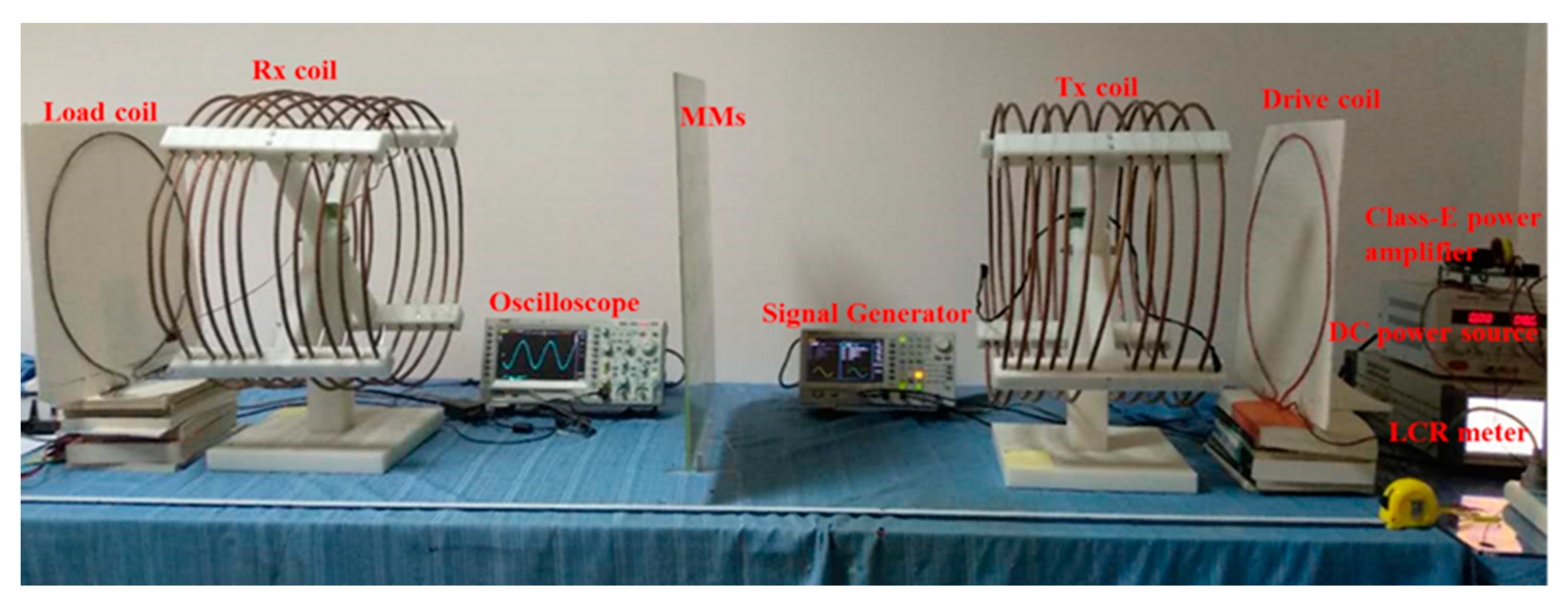
To verify the proposed the method, a four-coil WPT system with the MMs was built, as shown in
Figure 11. The radius of the
Tx coil was set to 25 cm, a turn of 10, and a pitch of 4 cm, with the radius of the copper tube as 4 mm, the same as the Rx coil. Additionally, both the drive loop and the load loop were the single turn circular coil with a diameter of 40 cm. The additional capacitor was welded to the four coils to achieve a resonant frequency of 2.80 MHz. The parameters of the four-coil WPT system is shown in
Table 3. For simplification, the skin effect and proximity effect were ignored. The unit cells were assembled periodically as a 5 × 5 MMs slab. The MMs slab was located between the
Tx coil and the
Rx coil. All the modules, including the drive loop, the
Tx coil, the MMs slab, the
Rx coil, and the load loop, were placed coaxially. The DC power source supplied energy for the Class-E amplifier, the signal generator emitted the high frequency PWM electrical level, and the oscilloscope measures the waveform of the output resistance. The MMs was located between the
Rx coil and the
Tx coil and the position of the MMs changed along with the distance between the
Rx coil and the
Tx coil accordingly.
Firstly, we changed the distance between the load loop and the Rx coil to achieve the optimal load, and then changed the distance between the drive loop and the Tx coil to attain the needed Zin of the Class-E amplifier. The LCR meter was to make sure that the output resistance, Zin, was equal to about 10 Ω by varying the distance between the two coils.
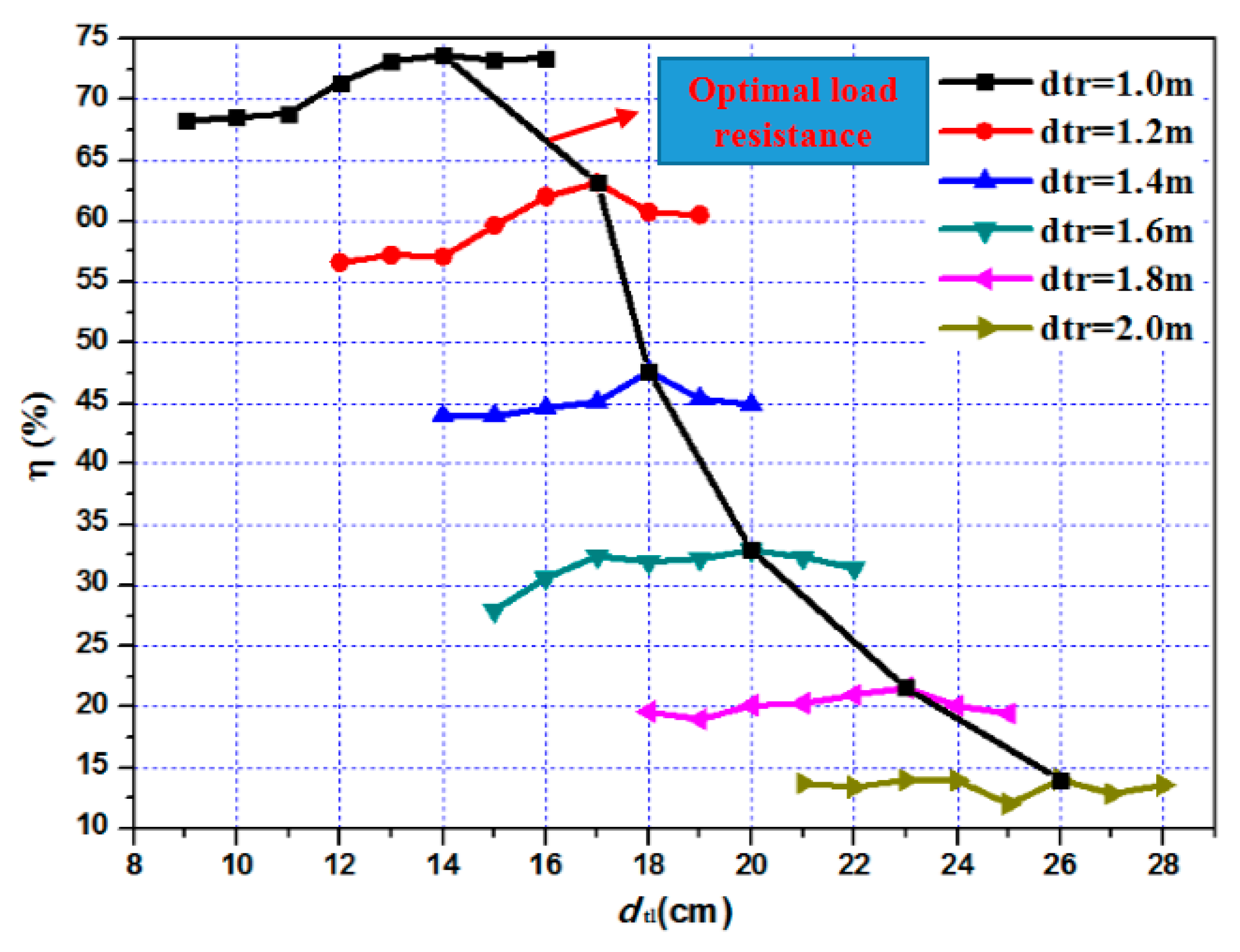
Figure 12 shows the optimal load by changing the distance between the load loop and the
Rx coil in the four-coil WPT system without MMs.
dtl denotes the distance between the load loop and the
Rx coil.
dtr represents the distance between the
Tx coil and the
Rx coil. When the
dtr was fixed at a certain value, the
dtr was varied to achieve the maximum efficiency. It can be seen that as the system transfer distance,
dtr, increased, the optimal distance of
dtl increased. Changes of the coil distances resulted in variations of the coupling coefficient. This experimental phenomenon is in good agreement with the previous analysis.
Table 4 lists the measured power results of the WPT system with the MMs. The magnitudes of the input current is
I1, and the input and output voltages are
V1 and
V2, respectively.
V1 and
I1 were obtained from the DC power source.
V2 was measured by an oscilloscope. The load resistance,
RL, was 10 Ω, and the output power
PL was calculated as the radio of the square of the output voltage,
V2, to the load resistance,
RL. The system power efficiency was derived by the expression, η =
PL/
V1I1. This table lists a set of measured data and manifests that the system output power can reach 5w approximately of 20.11% efficiency when the transfer distance was 200 cm.
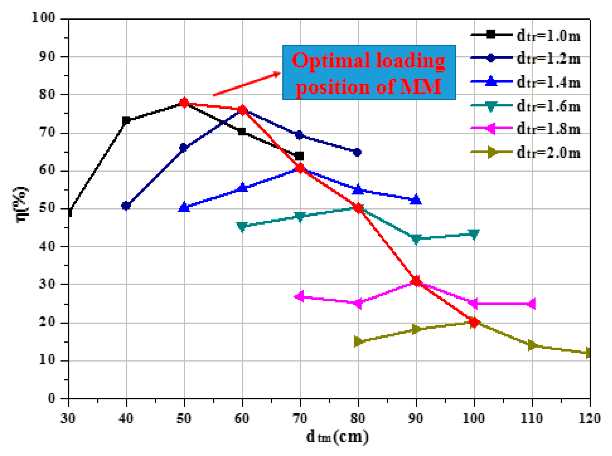
Figure 13 shows the measured results for the optimal loading position of the MMs in the WPT system.
dtr represents the distance between the
Tx coil and the
Rx coil and
dtm denotes the distance between the
Tx coil and the MMs. The distance of the
Tx coil and the
Rx coil was fixed to a certain value, varying from 1 m to 2 m, as labeled in the upper right area of the figure. The MM slab was moved 10cm apart between the
Tx coil and the
Rx coil at the certain
dtr, as shown in the x-coordinate of the figure. It can be seen that the transfer efficiency decreased when the
dtr increased. Furthermore, the transfer efficiency reached the maximum when the MMs slab was placed in the middle of the two coils approximately and the MM’s optimum loading position increased with the enhancement of the transmission distance generally.
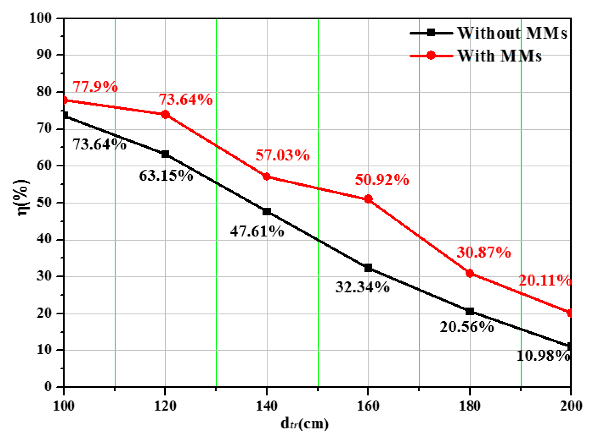
Figure 14 compares the measured transfer efficiency of the WPT system with/without the MMs. Obviously, the MMs contributed to the efficiency improvement for the mid-range WPT system. The strength of coupling between the
Tx coil and the
Rx coil was large when the two coils were closer together, so the MMs have little effect on the efficiency. However, the MMs was very useful for efficiency enhancement as the transfer distance became larger. The transfer efficiency improved by 3.26% when the
Rx coil and
Tx coil were 100 cm apart. On the contrary, the MMs enabled the WPT system to remain highly efficient when the two coils were far apart from each other. The transfer efficiency was enhanced by 9.13% when the transfer distance was 200 cm apart. In particular, the transfer efficiency was maximized up to 18.58% at 160 cm.

 ,
, 


