State-of-the-Art of Cellulose Nanocrystals and Optimal Method for their Dispersion for Construction-Related Applications

 , , , , and
Abstract
:1. Introduction
2. Review of Existing Research
3. Application of CNCs
3.1. CNC-Based Nanocomposites
3.2. Use of CNCs in Construction Applications
4. Test Methods
5. Results and Discussion
6. Conclusions
Author Contributions
Funding
Acknowledgments
Conflicts of Interest
References
- Un, K.Y. Present and future of nano-cellulose. NICE 2016, 34, 500–504. [Google Scholar]
- Eriksen, Ø.; Syverud, K.; Gregersen, Ø. The use of microfibrillated cellulose produced from kraft pulp as strength enhancer in TMP paper. Nord. Pulp Pap. Res. J. 2008, 23, 299–304. [Google Scholar] [CrossRef]
- Siró, I.; Plackett, D. Microfibrillated cellulose and new nanocomposite materials: A review. Cellulose 2010, 17, 459–494. [Google Scholar] [CrossRef]
- Chakraborty, A.; Sain, M.; Kortschot, M. Cellulose microfibrils: A novel method of preparation using high shear refining and cryocrushing. Holzforschung 2005, 59, 102–107. [Google Scholar] [CrossRef]
- Chen, W.; Yu, H.; Liu, Y.; Hai, Y.; Zhang, M.; Chen, P. Isolation and characterization of cellulose nanofibres from four plant cellulose fibres using a chemical-ultra\-sonic process. Cellulose 2011, 18, 433–442. [Google Scholar] [CrossRef]
- Dufresne, A. Nanocellulose: From Nature to High Performance Tailored Materials; Walter de Gruyter GmbH: Berlin, Germany, 2013. [Google Scholar]
- Börjesson, M.; Westman, G. Cellulose—Fundamental aspects and current trends. In Chapter 7: Crystalline Nanocellulose—Preparation, Modification, and Properties; Chalmers University of Technology: Göteborg, Sweden, 2015. [Google Scholar]
- Dong, X.M.; Kimura, T.; Revol, J.-F.; Gray, D.G. Effects of ionic strength on the isotropic-chiral nematic phase transition of suspensions of cellulose crystallites. Langmuir 1996, 12, 2076–2082. [Google Scholar] [CrossRef]
- Rojas, O.J.; Montero, G.A.; Habibi, Y. Electrospun nanocomposites from polystyrene loaded with cellulose nanowhiskers. J. Appl. Polym. Sci. 2009, 113, 927–935. [Google Scholar] [CrossRef]
- Bai, W.; Holbery, J.; Li, K. A technique for production of nanocrystalline cellulose with a narrow size distribution. Cellulose 2009, 16, 455–465. [Google Scholar] [CrossRef]
- Araki, J.; Wada, M.; Kuga, S.; Okano, T. Flow properties of microcrystalline cellulose suspension prepared by acid treatment of native cellulose. Colloids Surf. A Phys. Eng. Asp. 1998, 142, 75–82. [Google Scholar] [CrossRef]
- Fahma, F.; Iwamoto, S.; Hori, N.; Iwata, T.; Takemura, A. Effect of pre-acid-hydrolysis treatment on morphology and properties of cellulose nanowhiskers from coconut husk. Cellulose 2011, 18, 443–450. [Google Scholar] [CrossRef]
- Dong, X.M. Effect of microcrystallite preparation conditions on the formation of colloid crystals of cellulose. Cellulose 1998, 5, 19–32. [Google Scholar] [CrossRef]
- Henriksson, M.; Henriksson, G.; Berglund, L.A.; Lindström, T. An environmentally friendly method for enzyme-assisted preparation of microfibrillated cellulose (MFC) nanofibres. Eur. Polym. J. 2007, 43, 3434–3441. [Google Scholar] [CrossRef]
- Man, Z.; Muhammad, N.; Sarwono, A.; Bustam, M.A.; Kumar, M.V.; Rafiq, S. Preparation of cellulose nanocrystals using an ionic liquid. J. Polym. Environ. 2011, 19, 726–731. [Google Scholar] [CrossRef]
- Cao, Y.; Zavaterri, P.; Youngblood, J.; Moon, R.; Weiss, J. The influence of cellulose nano crystal additions on the performance of cement paste. Cem. Concr. Compos. 2015, 56, 73–83. [Google Scholar] [CrossRef]
- Alain, D. Nanocellulose: A new ageless bionanomaterial. Mater. Today 2013, 16, 220–227. [Google Scholar]
- Mazlan, D.; Din, M.F.M.; Tokoro, C.; Ibrahim, I.S. Cellulose nanocrystals addition effects on cement mortar matrix properties. Int. J. Adv. Mech. Civ. Eng. 2016, 3, 44–48. [Google Scholar]
- Fu, T.; Montes, F.; Suraneni, P.; Youngblood, J.; Weiss, J. The influence of cellulose nanocrystals on the Hydration and Flexural Strength of Portland Cement Pastes. Polymers 2017, 9, 424. [Google Scholar] [CrossRef]
- Cao, Y.; Zavattieri, P.; Youngblood, J.; Moon, R.; Weiss, J. The relationship between cellulose nanocrystal dispersion and strength. Constr. Build. Mater. 2016, 119, 71–79. [Google Scholar] [CrossRef] [Green Version]
- Cao, Y.; Tian, N.; Bahr, D.; Zavattieri, P.D.; Youngblood, J.; Moon, R.J.; Weiss, J. The influence of cellulose nanocrystals on the microstructure of cement paste. Cem. Concr. Compos. 2016, 74, 164–173. [Google Scholar] [CrossRef]
- Siqueira, G.; Bras, J.; Follain, N.; Belbekhouche, S.; Marais, S.; Dufresne, A. Thermal and mechanical properties of bio-nanocomposites reinforced by Luffa cylindrica cellulose nanocrystals. Carbohydr. Polym. 2013, 91, 711–717. [Google Scholar] [CrossRef]
- Heux, L.; Chauve, G.; Bonini, C. Nonflocculating and chiral-nematic self-ordering of cellulose microcrystals suspensions in nonpolar solvents. Langmuir 2000, 16, 8210–8212. [Google Scholar] [CrossRef]
- Pei, A.; Zhou, Q.; Berglund, L.A. Functionalized cellulose nanocrystals as biobased nucleation agents in poly(l-lactide)(PLLA)-Crystallization and mechanical property effects. Compos. Sci. Technol. 2010, 70, 815–821. [Google Scholar] [CrossRef]
- Kloser, E.; Gray, D.G. Surface grafting of cellulose nanocrystals with poly(ethylene oxide) in aqueous media. Langmuir 2010, 26, 13450–13456. [Google Scholar] [CrossRef] [PubMed]
- Habibi, Y.; Dufresne, A. Highly filled bionanocomposites from functionalized polysaccharide nanocrystals. Biomacromolecules 2008, 9, 1974–1980. [Google Scholar] [CrossRef] [PubMed]
- Mendez, J.; Annamalai, P.K.; Eichhorn, S.J.; Rusli, R.; Rowan, S.J.; Foster, E.J.; Weder, C. Bioinspired mechanically adaptive polymer nanocomposites with water-activated shape-memory effect. Macromolecules 2011, 44, 6827–6835. [Google Scholar] [CrossRef]
- Dagnon, K.L.; Shanmuganathan, K.; Weder, C.; Rowan, S.J. Water-triggered modulus changes of cellulose nanocomposites with hydrophobic polymer matrices. Macromolecules 2012, 45, 4707–4715. [Google Scholar] [CrossRef]
- Espino-Pérez, E.; Bras, J.; Ducruet, V.; Guinault, A.; Dufresne, A.; Domenek, S. Influence of chemical surface modification of cellulose nanowhiskers on thermal, mechanical, and barrier properties of poly(lactide) based bionanocomposites. Eur. Polym. J. 2013, 49, 3144–3154. [Google Scholar] [CrossRef]
- Landry, V.; Alemdar, A.; Blanchet, P. Nanocrystalline cellulose: Morphological, physical and mechanical properties. Prod. J. 2011, 61, 104–112. [Google Scholar] [CrossRef]
- Boufi, S.; Kaddami, H.; Dufresne, A. Mechanical performance and transparency of nanocellulose reinforced polymer nanocomposites. Macromol. Mater. Eng. 2014, 299, 560–568. [Google Scholar] [CrossRef]
- Cho, J.W.; Cho, D.H.; Choi, T.J. Nanocellulose Technology and Application Industry Trend; KEIT PD Issue Report; Sejong University: Seoul, Korea, 2017; Volume 17, pp. 17–29. [Google Scholar]
- Zoppe, J.O.; Ruottinen, V.; Ruotsalainen, J.; Rönkkö, S.; Johansson, L.-S.; Hinkkanen, A.; Järvinen, K.; Seppälä, J. Nanocrystals carrying tyrosine sulfate mimetic ligands and inhibition of alphavirus infection. Biomacromolecules 2014, 15, 1534. [Google Scholar] [CrossRef]
- Fang, Z.; Zhu, H.; Yuan, Y.; Ha, D.; Zhu, S.; Preston, C.; Chen, Q.; Li, Y.; Han, X.; Lee, S.; et al. Novel nanostructured paper with ultrahigh transparency and ultrahigh haze for solar cells. Nano Lett. 2014, 14, 765–773. [Google Scholar] [CrossRef] [PubMed]
- Lee, J.Y.; Kim, E.H.; Park, T.U.; Jo, H.M.; Kim, C.H.; Jeun, J.P. Development of metal ion absorbing filter using cellulose nanofibrils. J. Korea Tappi 2017, 49, 95–101. [Google Scholar]
- Pushparaj, V.L.; Shaijumon, M.M.; Kumar, A.; Murugesan, S.; Ci, L.; Vajtai, R.; Linhardt, R.J.; Nalamasu, O.; Ajayan, P. Flexible energy storage devices based on nanocomposite paper. Proc. Natl. Acad. Sci. USA 2007, 104, 13574–13577. [Google Scholar] [CrossRef] [PubMed] [Green Version]
- Okahisa-Kobayashi, Y.; Yoshida, A.; Miyahuchi, S.; Yano, H. Optically transparent wood–cellulose nanocomposite as a base substrate for flexible organic light-emitting diode displays. Compos. Sci. Technol. 2009, 69, 1958–1961. [Google Scholar] [CrossRef]
- Hübler, A.; Trnovec, B.; Zillger, T.; Ali, M.; Wetzold, N.; Mingebach, M.; Wagenpfahl, A.; Deibel, C.; Dyakonov, V. Printed Paper Photovoltaic Cells. Adv. Energy Mater. 2011, 1, 1018–1022. [Google Scholar] [CrossRef]
- Barr, M.C.; Rowehl, J.A.; Xu, J.; Wang, A.; Boyce, C.M.; Im, S.G.; Bulović, V.; Gleason, K.K. Direct monolithic integration of organic photovoltaic circuits on unmodified paper. Adv. Mater. 2011, 23, 3500–3505. [Google Scholar] [CrossRef] [PubMed]
- Yibo, Y.; Zhenming, C.; Xiaoding, W.; Xinxing, Z.; Guiping, Y. Nanoporous cellulose membrane doped with silver for continuous catalytic decolorization of organic dyes. Cellulose 2018, 25, 2547–2558. [Google Scholar]
- Partha, S.; Virginia, D.A. Photonic properties and applications of cellulose nanocrystal films with planar anchoring. Appl. Nano Mater. 2018, 1, 2175–2183. [Google Scholar]
- Singh, L.P.; Goel, A.; Bhattacharyya, S.K.; Ahalawat, S.; Sharma, U.; Mishra, G. Effect of morphology and dispersibility of silica nanoparticles on the mechanical behaviour of cement mortar. Int. J. Concr. Struct. Mater. 2015, 9, 207–217. [Google Scholar] [CrossRef]
- Roychand, R.; De silva, S.; Law, D.; Setunge, S. Micro and nano engineered high volume ultrafine fly ash cement composite with and without additives. Int. J. Concr. Struct. Mater. 2016, 10, 113–124. [Google Scholar] [CrossRef]


| Authors | Synopsis |
|---|---|
| Cao et al. [13] | Investigated the effect of addition of CNCs on cement paste. Highest ball-on-three-ball (B3B) flexural strength (strength increased by ~30%) was observed after the addition of 0.2 vol% CNCs and longer curing times. At higher CNC concentrations, an agglomeration of NCs occurred, resulting in a decrease in strength. |
| Siqueira et al. [22] | Use of sisal fibers as a source of CNCs as well as cellulose whiskers and microfibrillated cellulose (MFC). CNCs, cellulose whiskers, and MFC were obtained from sisal fibers and modified with n-octadecyl isocyanate. Efficiency of chemical transformation was found to be highly dependent on the nature of the nanoparticles, with explanations relating to specific areas, peeling ability, and solvent dispersion. Surface modification with n-octadecyl isocyanate improved the dispersion of nanoparticles in organic solvents. It is possible to form nanocomposite films on a wide range of polymer matrices by casting/evaporation techniques. |
| Heux et al. [23] | Electrostatic repulsion between cellulose microcrystals (CMCs) is inefficient in nonpolar organic solvents, while strong hydrogen bonding between MCs induces the rapid aggregation of colloidal suspension. As many applications require a good dispersion of the filler phase, this type of aggregation limits the range of solvents that can be used for forming CMC suspensions. The chemical modification of microcrystalline surfaces is an effective approach for improving their dispersion. |
| Pei et al. [24] | Unmodified and silylated CNCs (SCNCs) were prepared and used to solution-cast nanocomposite films of poly-L-lactic acid (PLLA). The effects of surface silylation on the morphology, nonisothermal, and isothermal crystallization behaviors, and mechanical properties of nanostructured composites were investigated. Unmodified CNCs formed agglomerates, whereas SCNCs were well dispersed in PLLA. The tensile modulus and tensile strength of PLLA/SCNC nanocomposite films containing only 1 wt% SCNCs were more than 20% higher than those of pure PLLA; this was owing to the crystallinity effects of SCNCs and their good dispersion. |
| Kloser and Gray [25] | The aqueous suspension of polyethylene oxide-grafted nanocrystalline cellulose (NCC) was prepared to obtain stereos instead of quenching stabilization. NCC suspension, which was prepared by sulfuric acid hydrolysis using a two-step process, was desulfurized with NaOH and functionalized with epoxy-terminated polyethylene oxide under alkaline conditions. |
| Habibi and Dufresne [26] | Cellulose and starch nanocrystals obtained from the acid hydrolysis of ramie fibers and waxy cornstarch granules can be used to graft polycaprolactone (PCL) rings with varying molecular weights onto surfaces through isocyanate-mediated reactions. It was confirmed that when PCL rings are grafted onto the surfaces of cellulose nanoparticles, the modulus decreases, while the fracture strain becomes higher than that of unmodified nanoparticles (i.e., modified nanoparticles exhibit excellent ductility). This can be ascribed to the entanglement and crystallization of the rings, namely, to the phenomenon of crystal reinforcement. |
| Mendez et al. [27] | The shape-memory effect of cotton cellulose nanowhiskers (CNWs) was investigated. The addition of CNWs increased the modulus of nanocomposites, resulting in a significantly higher elastic modulus. A high elastic modulus is essential for shape-memory effect. |
| Dagnon. [28] | Studied the production of cellulose from seaweeds. Nanocomposites were prepared using polyglutaric styrene, co-butadiene, and polybutadiene. Seaweed CNWs were used as highly elastic filler in the nanocomposites. In addition, the tensile dynamic modulus was determined through dynamic mechanical analysis, and interactions between the internal network and the nanomatrix were analyzed. |
| Espino-Pérez et al. [29] | Analyzed the compatibility of CNWs and poly (lactic) acid (PLA). PLA/CNWs bionanocomposites were synthesized and their thermal, mechanical, and barrier properties were evaluated. The surfaces of CNWs were modified by in situ grafting them onto PLA; this enhanced the tensile strength and increased the heat resistance of PLA. Further, surface grafting at low CNW-ICN(Cellulose nanowhiskers were grafted by n-octadecyl-isocyanate) concentrations led to improved compatibility. |
| Landry et al. [30] | Investigated change in the performance of films with the incorporation of NCCs. Effects on properties such as film morphology, rigidity, and heat resistance were analyzed in order to determine the suitability of NCCs as a reinforcement material. |
| Boufi et al. [31] | Mechanical performance and transparency of NC-reinforced polymer nanocomposites formed using CNCs and NFCs as reinforcement materials, and polymers with various aspect ratios were analyzed. The reinforcement effect in formed nanocomposite films was evaluated. |
| Technology | Description |
|---|---|
| Method for replicating biological structures on surfaces of CNCs (Aalto University and University of Eastern Finland) | The surface by using a method to mimic the biological structure on the surface of nano-sized cellulose crystals adsorbs the virus and destroys the function of the virus. The results of this study are expected to be useful for the development of antiviral ointment and surface. [33] |
| Transparent paper (University of Maryland, South China University of Technology, and University of Nebraska-Lincoln) | Developed transparent paper that can have high optical transparency (96%) and high degree of fogging (60%) simultaneously using nanocrystalline cellulose has very effective properties as a solar cell substrate [34]. |
| Cellulose nanofibers-based filter (Gyeongsang National University) | Improvement in wet strength due to the hydrophilic characteristics of cellulose nanofiber prepared by the mechanical treatment and formation of a cellulose nanofiber filter by layering the characteristics of the adsorption of a metal ion by a high anionic functional group of carboxylated cellulose nanofibers [35]. |
| Supercapacitors and batteries | A novel nanocellulose-based composite was fabricated for producing flexible energy storage devices. The device, which had a simple structure, used nanocellulose paper with good conductivity at room temperature as the separator, and was flexible because it employed multiwalled carbon nanotubes-based electrodes [36]. |
| Organic light-emitting diode (OLED) devices based on nanocellulose (Kyoto University) | OLEDs that show low thermal expansion coefficients (21 ppm/K) were recently developed using nanocellulose substrates. Various resins were used to produce transparent and flexible devices [37]. |
| Energy recovery device | 80% of the currently used solar panels are made of silicon, and have long lifetimes and good driving power. However, it is expensive to produce high-purity silicon, and the process is complicated, making mass production difficult. Nanocellulose is attracting attention as a novel flexible substrate for solar energy applications [38,39]. |
| Nanoporous cellulose membrane | A silver nanoparticles-doped bacterial cellulose (AgNP@BC) nanoporous membrane containing AgNPs with diameters of ~8.1 nm was successfully fabricated without employing any other reductants or capping or dispersing agents. The BC hydrogel with a 3D network not only acts as a stable scaffold, but also as a reductant for the synthesis of AgNPs. The as-prepared membrane exhibited high efficiency during the continuous catalytic decolorization of two typical organic dyes (rhodamine 6G and methyl orange), owing to its distinct nanoporous structure [40]. |
| CNC films | Cross-polarized reflected micrographs showing the effect of surface anchoring on planar orientation, CNC film dried in a water vapor-saturated environment assisted by orbital shear with coverslip (A) off and (B) on during drying. Uniform photonic properties were achieved over orders of magnitude with greater length scales by understanding the effects of initial concentration, orbital shear, surface anchoring, and drying conditions on the microstructure and photonic properties of fabricated films. In addition, the fabricated biomimetic films exhibited a double-peak spectrum similar to that of the chiral nematic photonic structure that was observed in Lomaptera beetles [41]. |
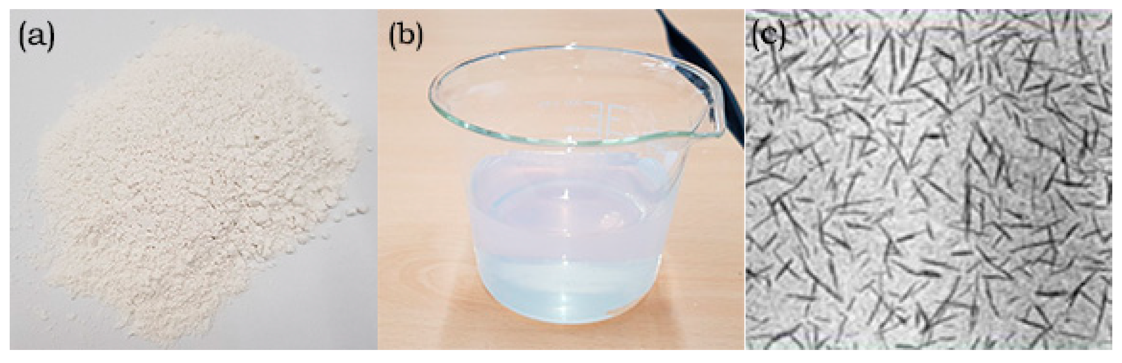
| Product Form | Appearance (Color) | Crystallite Density | Specific Surface Area | Particle Diameter (Crystallite) | Particle Length (Crystallite) | pH |
|---|---|---|---|---|---|---|
| Powder | White | 1.5 g/cm3 | 400 m2/g | 2.3–4.5 nm (by AFM) | 44–108 nm (by AFM) | 6–7 |
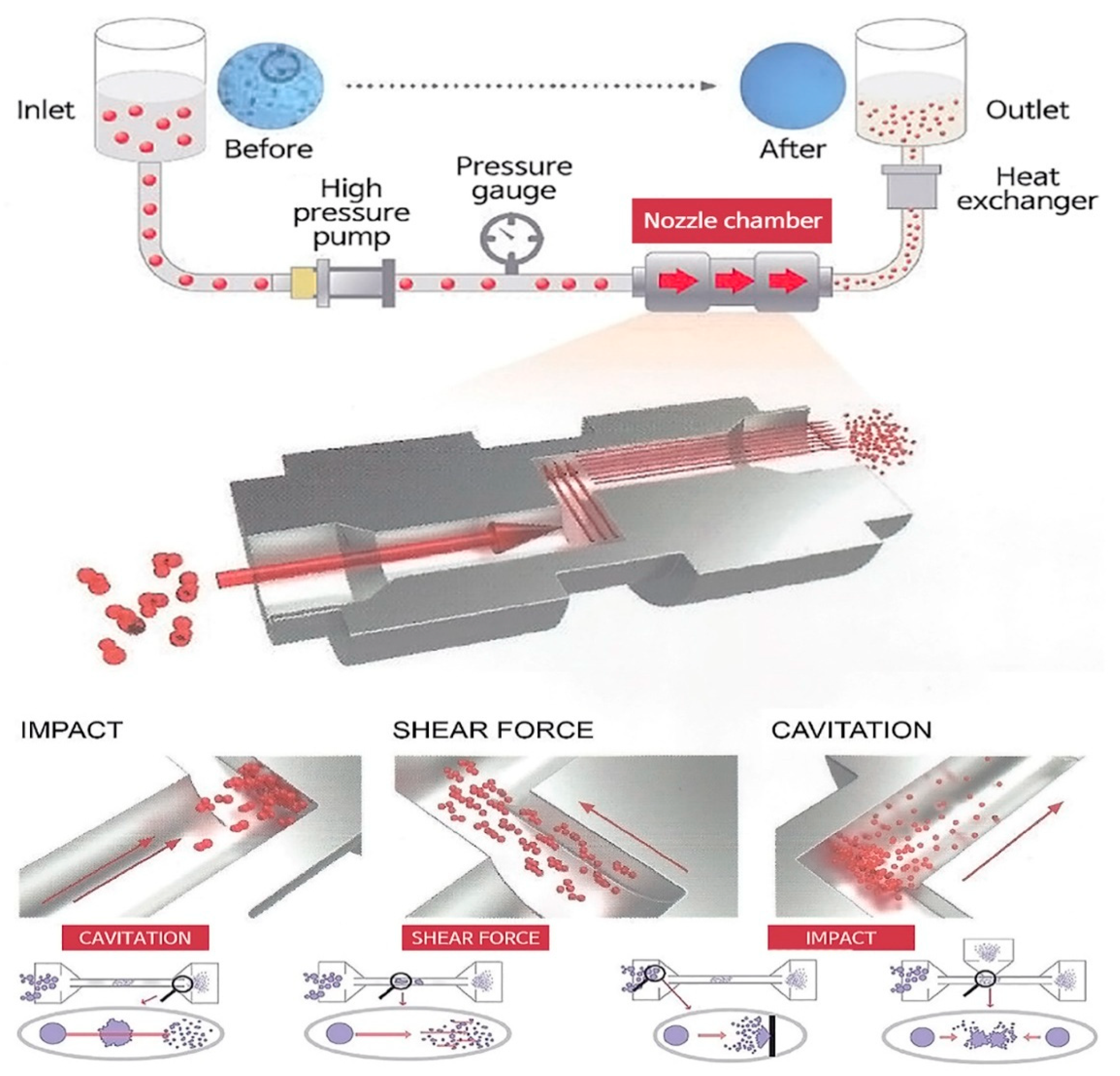
| Method | Dispersion Time | Speed (rpm)/Pressure (Pa) | Number of Dispersion Passes |
|---|---|---|---|
| Magnetic stirring | 1–3 h | 1500 | - |
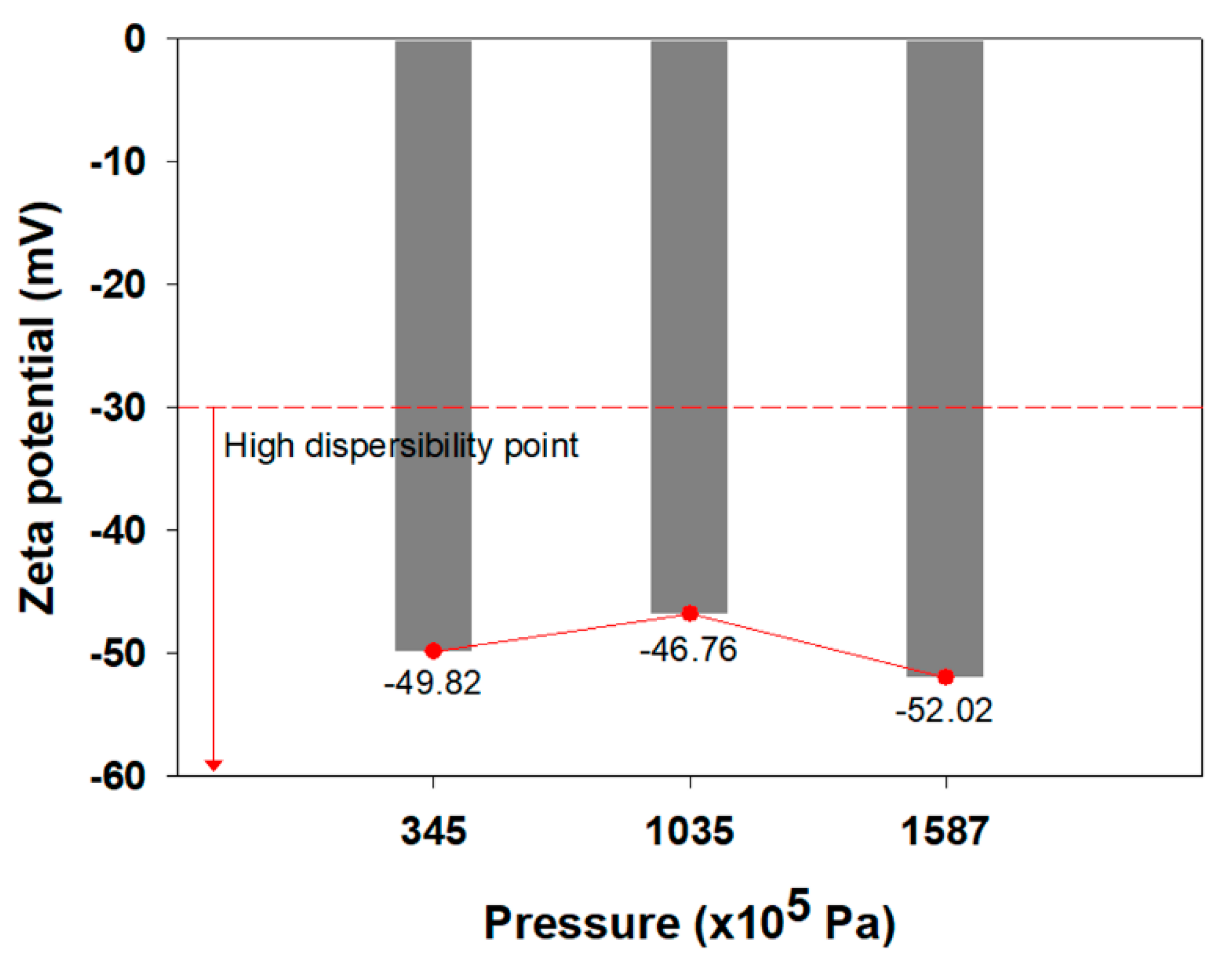
| High pressure dispersion | - | 345 × 105, 1035 × 105, 1587 × 105 | 1~3 |
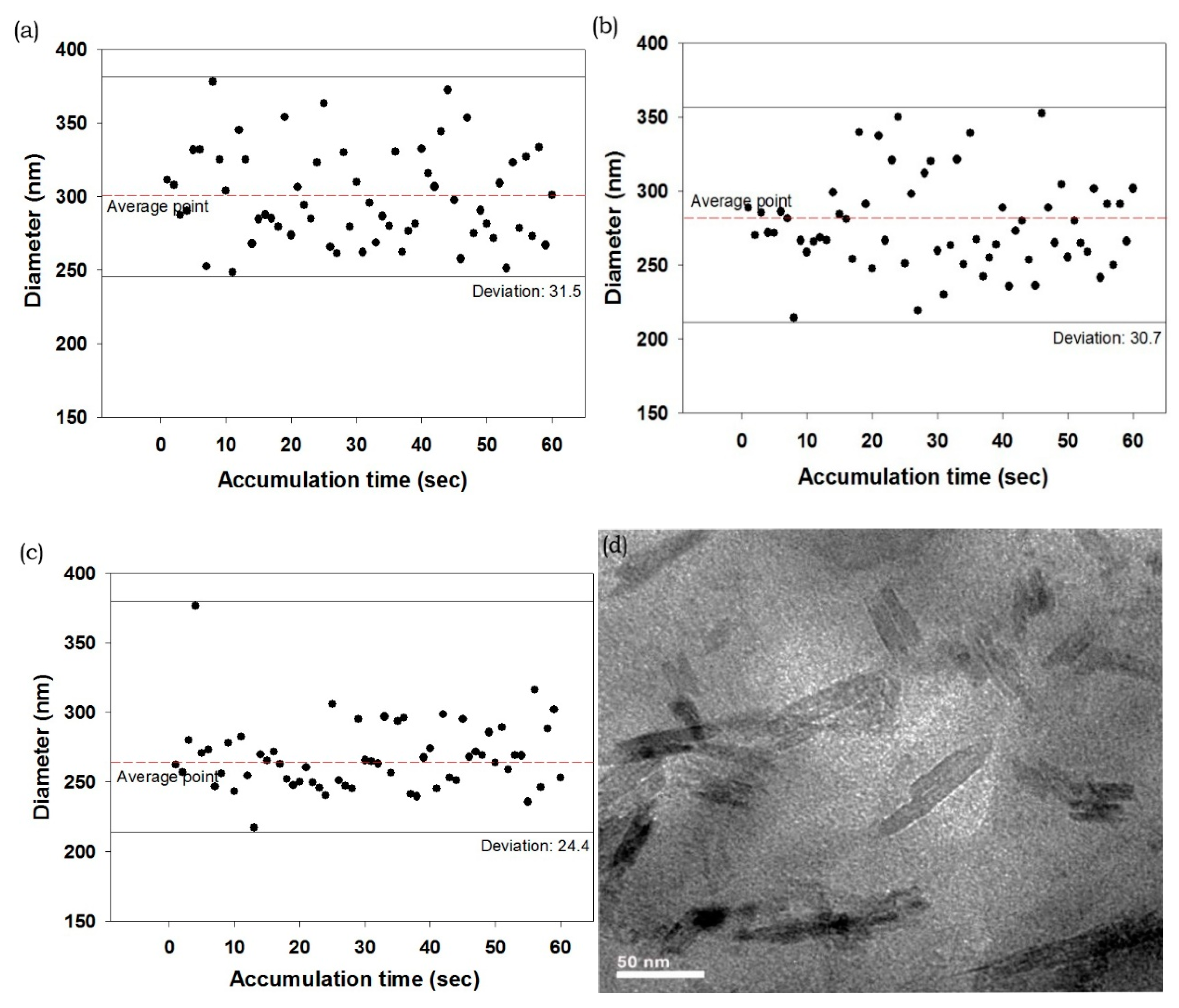
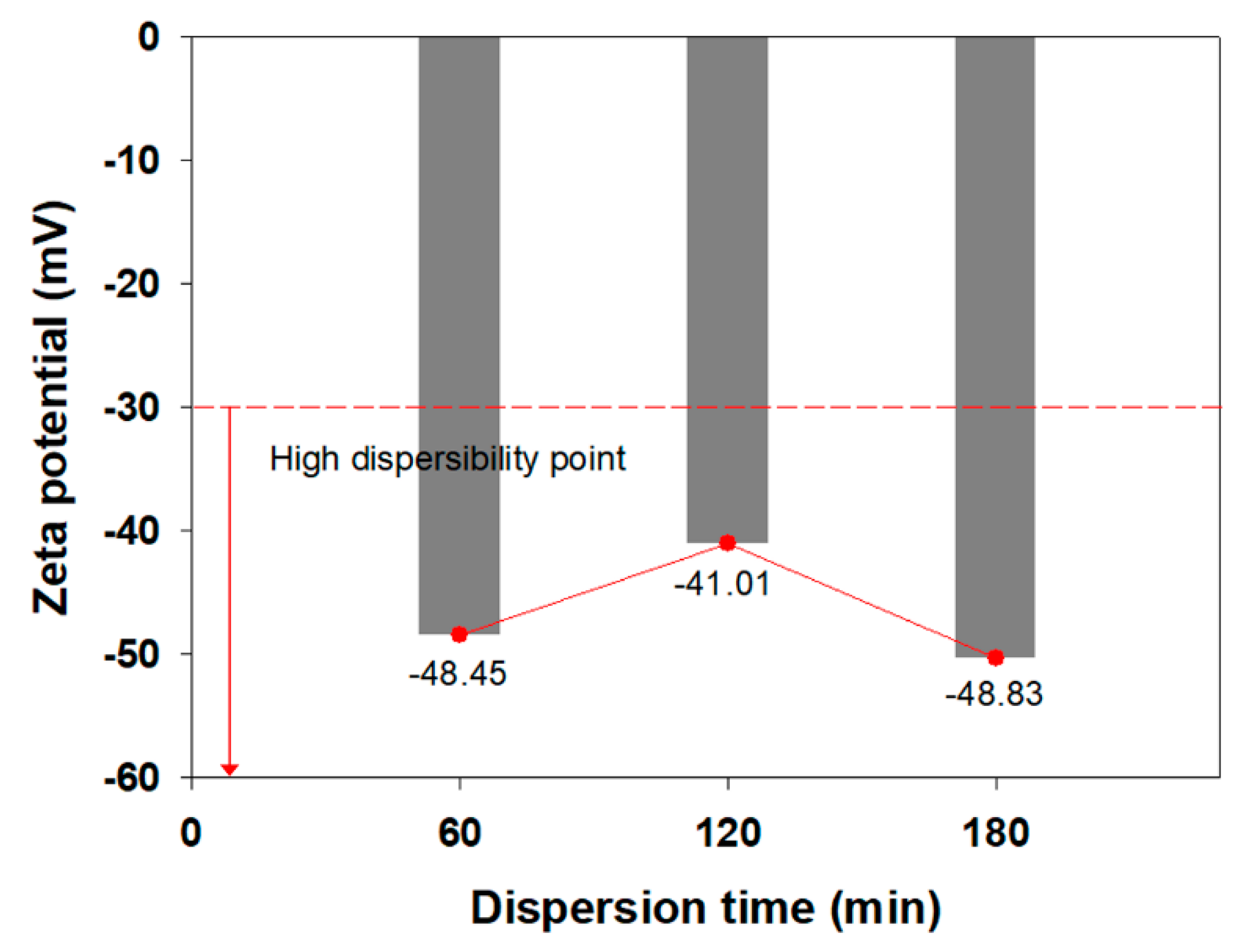
| Sample | Deviation (nm) | Diameter (nm) | Average Diameter (nm) |
|---|---|---|---|
| M-60 min | 31.5 | 300 | 281.6 ± 30 nm |
| M-120 min | 30.7 | 277.4 | |
| M-180 min | 24.4 | 267.5 |
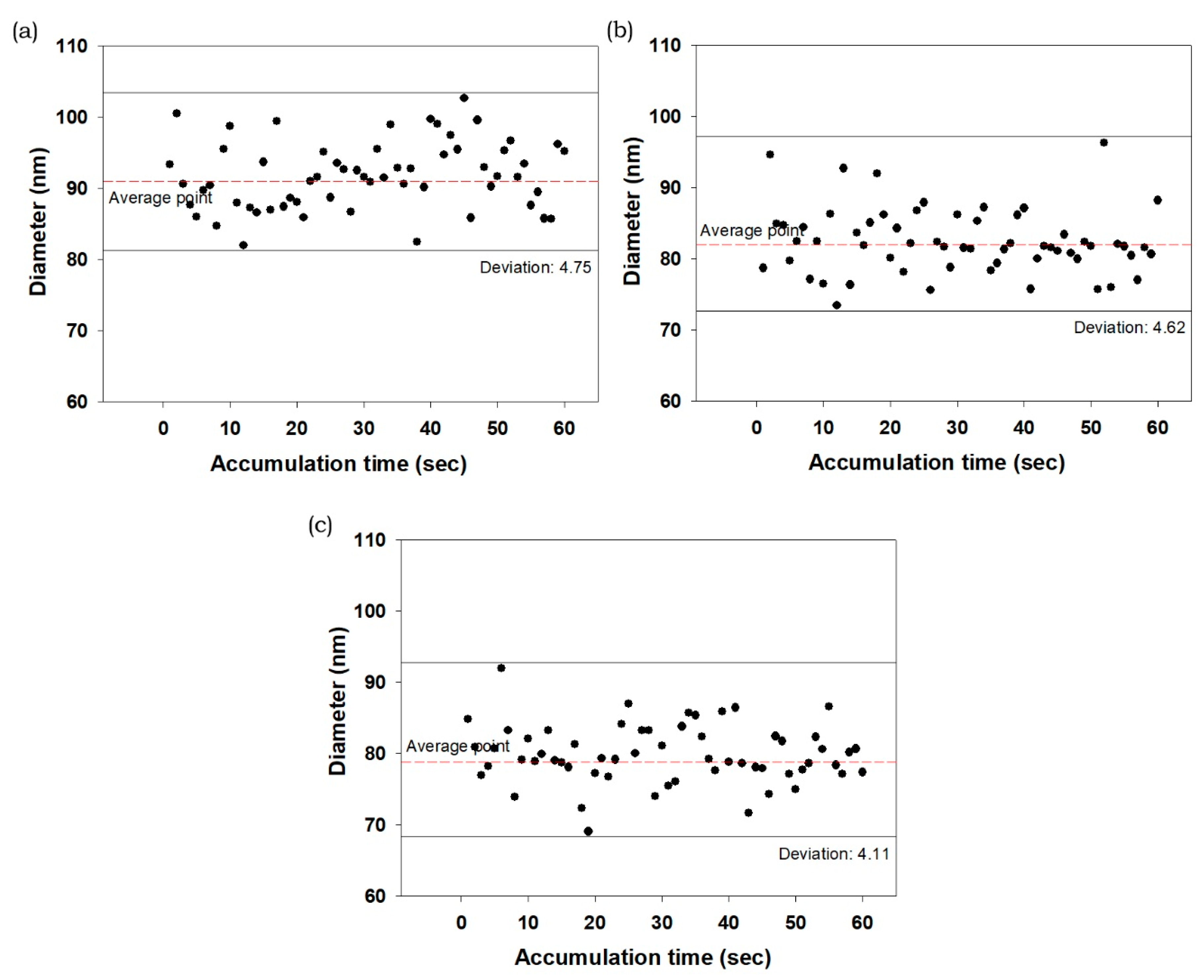
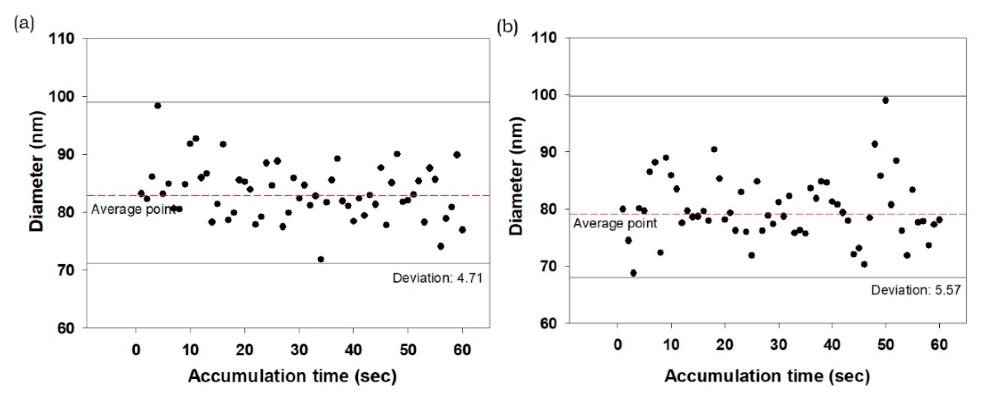
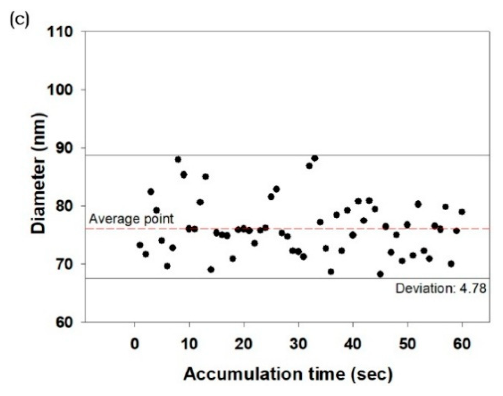
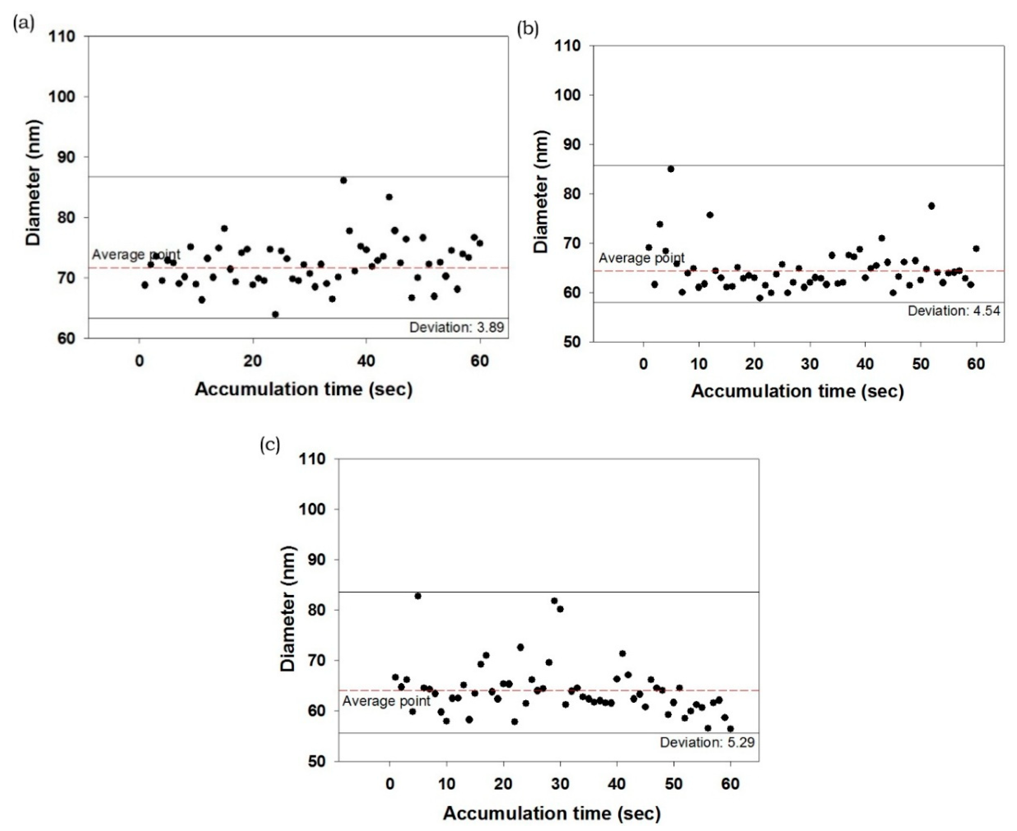
| Pass | Deviation (nm) | Diameter (nm) | Average Diameter (nm) | |
|---|---|---|---|---|
| 345 × 105 Pa | 1 | 4.7 | 91 | 84 |
| 2 | 4.6 | 82 | ||
| 3 | 4.1 | 79 | ||
| 1035 × 105 Pa | 1 | 4.7 | 83 | 79 |
| 2 | 5.5 | 79 | ||
| 3 | 4.7 | 76 | ||
| 1587 × 105 Pa | 1 | 3.8 | 72 | 67 |
| 2 | 4.5 | 64 | ||
| 3 | 5.2 | 64 |
© 2019 by the authors. Licensee MDPI, Basel, Switzerland. This article is an open access article distributed under the terms and conditions of the Creative Commons Attribution (CC BY) license (http://creativecommons.org/licenses/by/4.0/).
Share and Cite
Lee, H.-J.; Lee, H.-S.; Seo, J.; Kang, Y.-H.; Kim, W.; Kang, T.H.-K. State-of-the-Art of Cellulose Nanocrystals and Optimal Method for their Dispersion for Construction-Related Applications. Appl. Sci. 2019, 9, 426. https://doi.org/10.3390/app9030426
Lee H-J, Lee H-S, Seo J, Kang Y-H, Kim W, Kang TH-K. State-of-the-Art of Cellulose Nanocrystals and Optimal Method for their Dispersion for Construction-Related Applications. Applied Sciences. 2019; 9(3):426. https://doi.org/10.3390/app9030426
Chicago/Turabian StyleLee, Hyung-Joo, Heon-Seok Lee, Junwon Seo, Yong-Hak Kang, Woosuk Kim, and Thomas H.-K. Kang. 2019. "State-of-the-Art of Cellulose Nanocrystals and Optimal Method for their Dispersion for Construction-Related Applications" Applied Sciences 9, no. 3: 426. https://doi.org/10.3390/app9030426