Effects of Atmospheric Turbulence on OAM-POL-FDM Hybrid Multiplexing Communication System


1
Guangdong Provincial Key Laboratory of Nanophotonic Functional Materials and Devices, Guangzhou 510006, China
2
Department of Optical Engineering, South China Normal University, Guangzhou 510006, China
*
Author to whom correspondence should be addressed.
Appl. Sci. 2019, 9(23), 5063; https://doi.org/10.3390/app9235063
Submission received: 26 October 2019
/
Revised: 20 November 2019
/
Accepted: 21 November 2019
/
Published: 23 November 2019
(This article belongs to the Section Optics and Lasers)
Abstract
:This paper proposes a 32-channel-hybrid-multiplexing system on atmospheric turbulence. With the utilization of the hybrid multiplexing of orbital angular momentum (OAM), polarization, and frequency, the communication speed of the system can be significantly improved, and this system can be well combined with the existing frequency division multiplexing (FDM) optical communication network. Within this communication system, we discuss the effects of different turbulence intensities on the phase, OAM crosstalk, spectrum, and bit error rate (BER) in turbulent channels. Under strong turbulence, 46.8% of the energy leaks to the neighbor OAM and become noise when multiple topological charge states are transmitted. The research reflects the impact of various parameters of the OAM hybrid multiplexing system under turbulence, which is closer to a practical application scenario and is significant for implementing OAM communication in the turbulence channel.
1. Introduction
The requirement of communication links with high data capacity is propelled by the exponential increase of data traffic [1]. Different multi-level modulation formats such as m-ary quadrature amplitude modulation (m-QAM) and multiplexing techniques (e.g., wavelength division multiplexing (WDM), time-division multiplexing (TDM), polarization division multiplexing (PDM), and OAM multiplexing) have been used to improve transmission capacity and spectral efficiency [2,3,4,5,6]. In addition, many multi-channel communication systems based on hybrid multiplexing have been proposed [1], such as the OAM-POL hybrid multiplexing system and the 26-OAM mode multiplexing system proposed by Jian Wang [7,8]. It has been proven that hybrid multiplexing can increase the transmission rate of communication systems [9]. Based on this, we propose a 32-channel-hybrid-multiplexing system that consists of OAM, polarization, and frequency division multiplexing (FDM) hybrid multiplexing [10,11]. Compared with the above-mentioned OAM-POL multiplexing, the system adds a dimension (i.e., FDM), which enables the system to be well integrated with existing communication networks and achieves larger data capacity.
Introducing the hybrid multiplexing system into the atmospheric turbulence channel and discussing the influence of turbulence on it will provide new ideas for improving the performance of free-space optical (FSO) communication systems. As a result, hybrid multiplexing has now become a focus in current FSO communication research [12,13,14,15,16]. In this paper, we used a hybrid multiplexing system that combines different multiplexing methods to transmit information in the atmospheric turbulence channel and studied the effects of atmospheric turbulence on the system [17,18,19]. Compared with the communication system in atmospheric turbulence that adopts the sole modulation method, the interaction between multiple multiplexing methods is considered in this study, which is derived from the superposition of different effects. Therefore, it is closer to the practical transmission environment and more practical in real scenarios. We simulated the propagation of an OAM beam under the influence of atmospheric turbulence by MATLAB and Optisystem. The influence of different atmospheric turbulence intensities for the hybrid multiplexed system were compared from phase, spectrum, OAM crosstalk, and BER. Consequently, the research conclusions can guide the realization of a hybrid multiplexed system under turbulence to a certain extent.
The content of the article is arranged as follows. In Section 2, we introduce the expressions of atmospheric turbulence and vortex beam transmission [20] as well as the schematic diagram of the 32-channel OAM-POL-FDM multiplexing system [8]. Next, in Section 3, we introduce the effects of different atmospheric turbulence intensities on the phase, spectrum, OAM crosstalk, and BER of OAM-POL-FDM hybrid multiplexing systems. Finally, the influences of different turbulence intensities on the system are discussed in Section 4. For example, in the state of strong turbulence (Cn2 = 10−14 m−2/3), 46.8% of the energy leaks to the neighbor OAM mode and becomes noise when multiple topological states are transmitted simultaneously.
2. Methods
2.1. Vortex Beam in Turbulence
In this paper, the transmission speed of the vortex beam was increased by combining OAM, polarization, and frequency. The vortex beam was generated by a Gaussian beam. The distribution of the complex-amplitude of the beam nested within the cross-section of the Gaussian beam with a center point at (x0, y0) can be expressed as [21]:
The sign of l determines whether the vortex beam rotates clockwise or counterclockwise, and the magnitude of l represents the topological charge of the vortex beam. is the beam waist radius of the host Gaussian beam. The amplitude at the center of the vortex beam is 0.
When multiple vortex beams are multiplexed together, their complex-amplitudes can be expressed as a function [22]:
In this expression, N is the number of vortex beams that are embedded in the cross-section of the Gaussian beam with radius . The order of the n-th vortex beam is ln, and its center is located at point (xn, yn) in the XY plane.
A multi-layer phase screen is used to simulate atmospheric turbulence. The refractive index power spectrum in the turbulence is the Kolmogorov type [23].
Cn2 is the refractive index constant, which denotes the turbulence intensity. Different numbers of phase screens indicate different turbulence intensities.
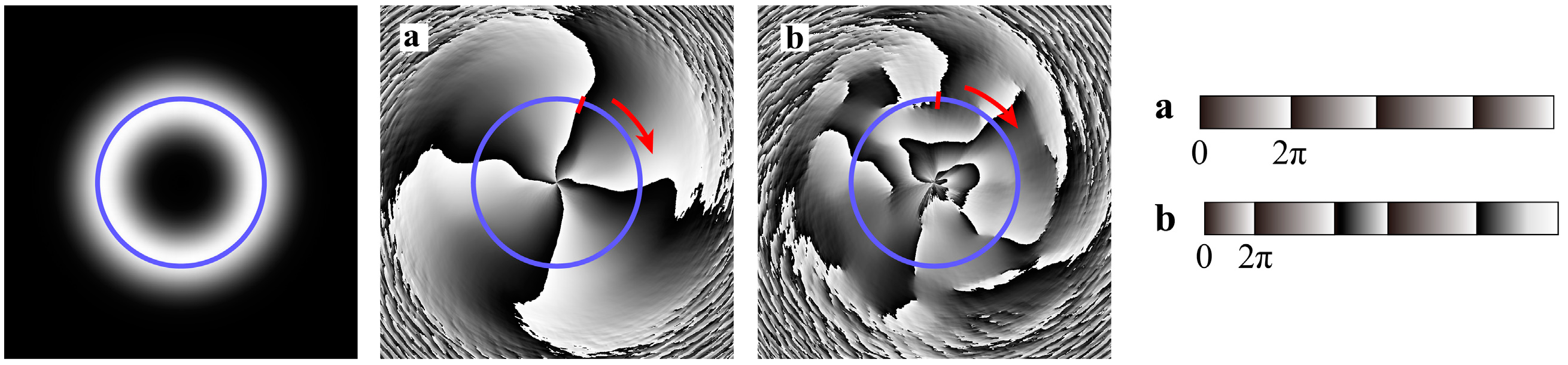
The original topological charge is changed when the vortex beam passes through the turbulent channel [24]. As shown in Figure 1, the circle denotes the projection of the intensity of the vortex beam and the number of topological charge, l, can be calculated based on the number of times that the phase is changed from 0 to 2π in the whole circle. Mathematically, l can be defined as the following path integral [25]:
where C denotes the closed integral path and dl means an infinitesimal vector unit. By using this method, the topological charge of the distorted beam can be calculated at the receiver.
2.2. Structure of 32-Channel-Hybrid-Multiplexing System
In this paper, as shown in Figure 2, a 32-channel OAM hybrid multiplexing communication system composed of modules of OAM, polarization, and frequency multiplexing was constructed. The specific structure is that every four vortex beams are combined into one beam by OAM multiplexing [26]. Then, two beams are combined by polarization multiplexing and each beam carries four OAM modes, so these eight beams converge into one. This method is used to implement the same processing on the remaining 24 beams so that 32 beam converge into four composite OAM beams. After that, these four beams are processed with FDM. At the end, the hybrid multiplexing of a 32-channel OAM can be realized by four different frequencies, and then the laser is transmitted to the atmosphere through the telescopic system.
At the receiver, optical signals of different frequencies are separated by frequency division de-multiplexing and four beams processed by polarization multiplexing and OAM multiplexing are obtained. Then, each of them is processed by polarization de-multiplexing and divided into two beams so that the four beams are divided into eight beams. After that, each of the eight beams experiences OAM de-multiplexing and is separated into four beams so the number of beams becomes 32 (4 × 2 × 4). Ultimately, the optical signal is converted into an electrical signal by a photodetector. The 32-channel multiplexing communication system is established by the OAM-POL-FDM hybrid multiplexing method. In this system, a continuous optical signal is generated by the transmitter and the transmission power is set in the range of −5 to 10 dB, according to our requirements. The center frequency of the optical signal is 193.4 THz. The modulator is a Mach-Zehnder modulator and the devices that produce the vortex beams are vortex lenses. Spatial PIN photodetectors with a responsivity of 1 A/W and dark current of 10 μA were adopted in the receiver.
3. Discussion on Transmission Performance under the Turbulence
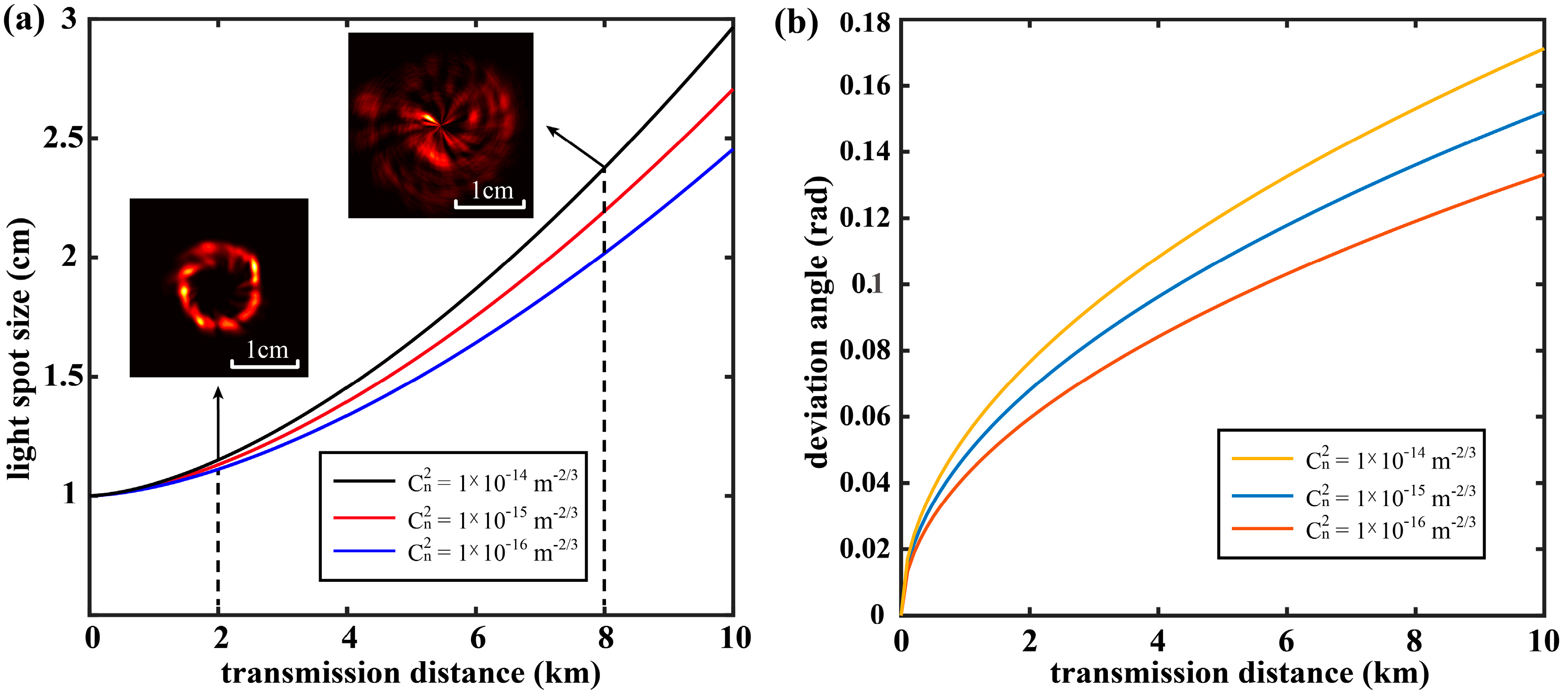
Different topological charges in OAM multiplexing determine the channel of communication, and the change of topological charge will influence the transmission of signals in the corresponding channel. We studied the influence of different transmission distances, turbulence intensities, and topological charges on the phase. The simulation was carried out under FSO atmospheric turbulence [27], and the results are shown in Figure 3a. At the same turbulence intensity, the size of the light spot increases with the increase in transmission distance. Due to the inhomogeneity of atmospheric mediators, increasing the turbulence intensity will increase the spot size. When the beam passes through a non-uniform atmosphere, it may come up with random refraction that will cause the beam spot size to become larger and the power is reduced after the beam is transmitted for a span of distance. This phenomenon can be optimized by increasing the optical power of transmission or adding optic devices with the function of converging beams at the receiving end. In addition, because of the existence of random refraction, the beam has a certain deviation angle after passing through the turbulent channel. As shown in Figure 3b, when the turbulence intensity is fixed, the deviation angle gradually increases as the transmission distance increases, and the intensification of turbulence also causes the increase in deviation angle under the same distance.
When a vortex beam with a topological charge of l = +8 is transmitted under turbulence with an intensity of Cn2 = 10−15 m−2/3 (moderate turbulence), its intensity is affected differently with the change in transmission distance. The phase is distorted as the transmission distance increases, as shown in Figure 4. It can be discovered that as the transmission distance increases, the optical field becomes increasingly scattered and the spot size also becomes larger [28]. The phase of the vortex beam is changed from the original regular phase distribution to a distorted spiral phase distribution. To completely receive the energy of the beam at the receiving end, receivers with a larger size or converging lens are required. When the size of the receiver aperture is kept constant, the rise of the transmission distance leads to a decrease in both the energy that enters the receiver and signal-to-noise ratio (SNR).
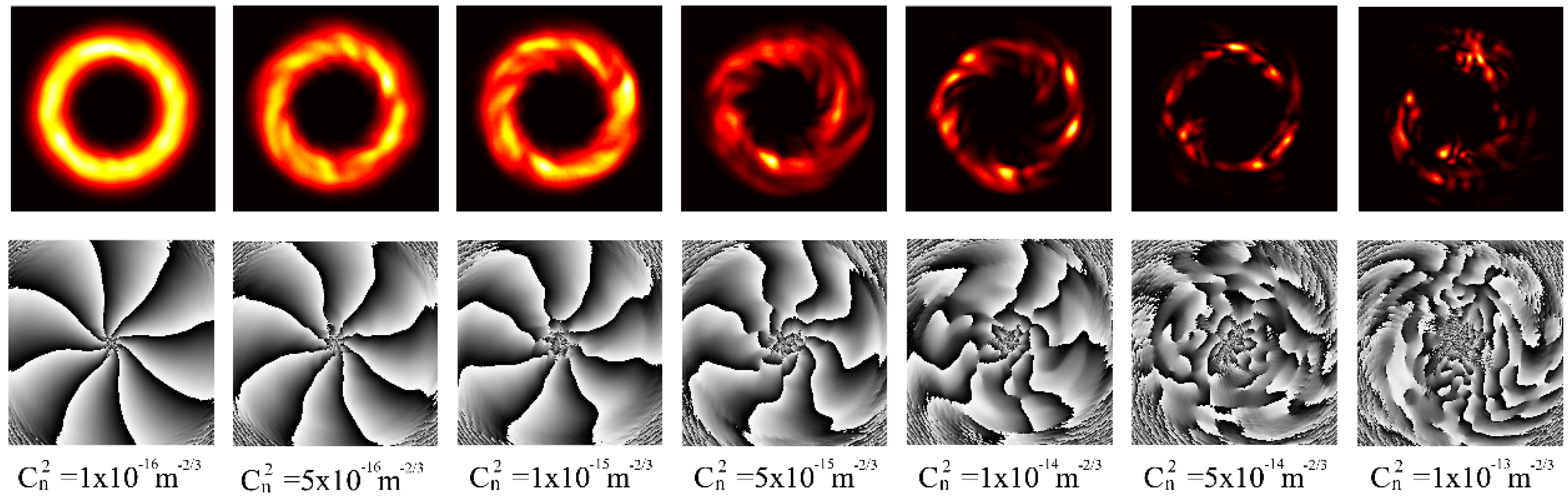
Figure 5 shows the intensity and phase distribution of a vortex beam of l = +8 at different turbulence intensities. The phase of the vortex beam is distorted as it passes through the atmospheric turbulence and the phase distortion will become more severe as the turbulence intensity increases [29]. When the turbulence intensity is higher than Cn2 = 10−14 m−2/3, the phase is almost indistinguishable. Therefore, when the transmission distance is 3 km, the turbulence intensity should be less than Cn2 = 5 × 10⁻¹⁵ m−2/3 to ensure that the phase can be distinguished and the receiver can separate the signals according to the phase.
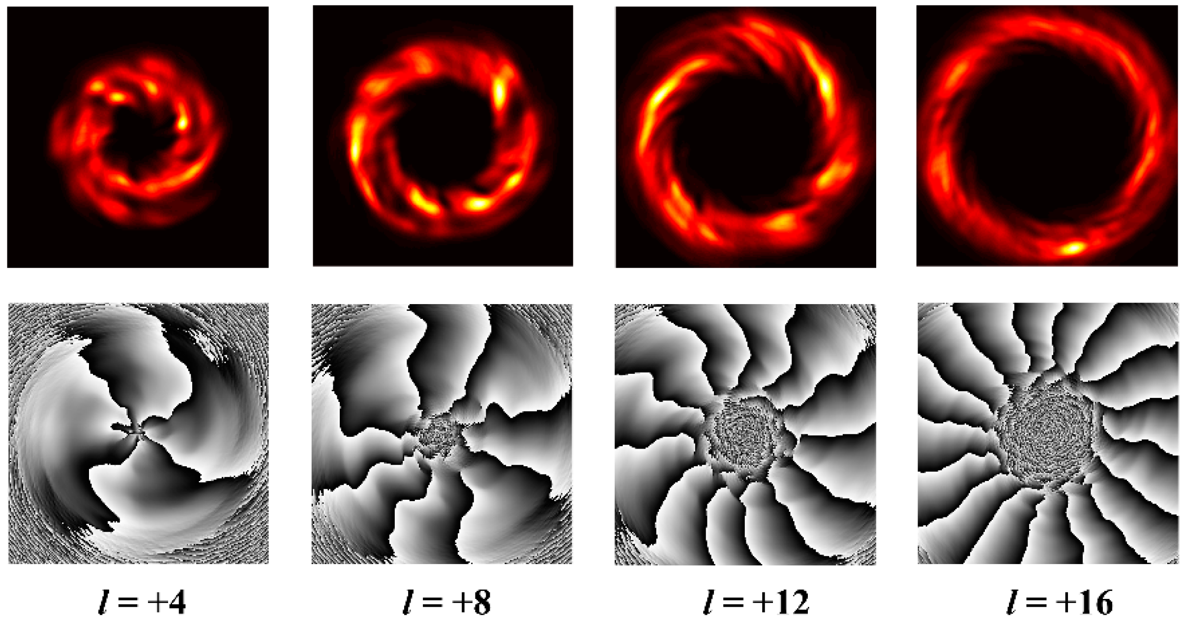
With constant transmission distance and turbulence intensity, when the topological charge is changed, the distributions of intensity and phase in the link are demonstrated in Figure 6. After long-distance transmission, the beam center is more susceptible when the topological charge increases. Phase distortion is more severe in central areas than in edge areas. The center of the vortex beam is the phase singularity, and the amplitude at the center is almost zero, so turbulence has a relatively larger impact on the phase of the position where the amplitude is small. In other words, the greater the influence on the phase when there is a larger topological charge, the more prone the phase of the central portion will be affected. Therefore, at the same turbulence intensity and transmission distance, when the topological charge is larger, the influence of turbulence on the central portion of the beam will be more severe.
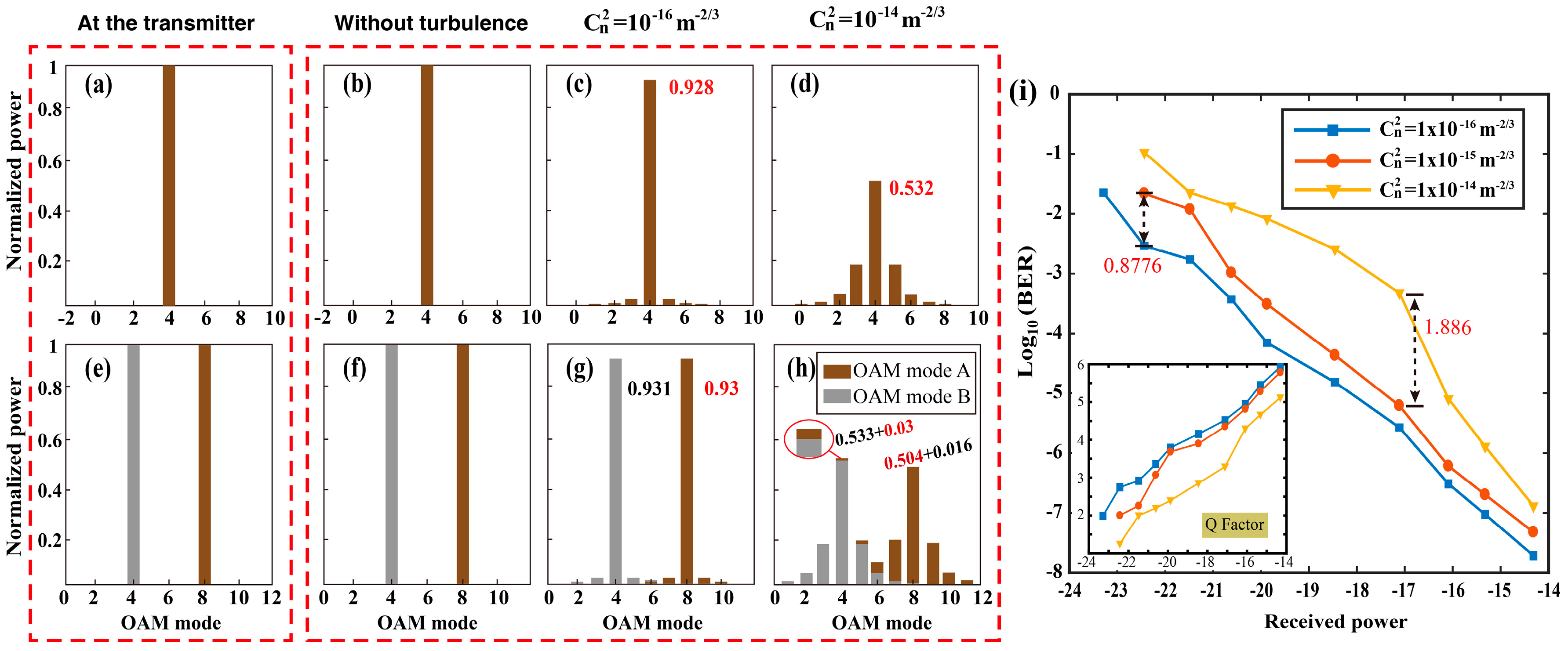
During the transmission, when the vortex beam is influenced by turbulence, the original topological charge will become a new topological charge due to the phase distortion, and energy leak will cause channel crosstalk between the vortex beams [30]. We compared the crosstalk of the OAM mode after the signal passed through the turbulent channel under different turbulence intensities and the results are shown in Figure 7. When the vortex beam passes through the turbulence channel, the OAM will leak from l = n to n ± 1, n ± 2,... Crosstalk will cause a power loss of the original OAM mode after long-distance transmission, while the noise of the neighbor OAM mode will increase [31]. Figure 7c,d reveal the crosstalk of the signal under turbulence. When the OAM beam passes through weak (Cn2 = 10−16 m−2/3) and strong (Cn2 = 10−14 m−2/3) turbulence, 7.2% and 46.8% of the energy is leaked into the neighbor OAM mode, respectively. When the turbulence intensity increases, the crosstalk becomes increasingly obvious and the energy distribution becomes more dispersed.
When two OAMs are multiplexed information transmission, mutual interference will occur between these two OAM modes [30,32,33]. Figure 7f–h depict the circumstance when two OAMs are transmitted simultaneously. In the case of weak turbulence (Cn2 = 10−16 m−2/3), approximately 7% of the energy leaks to other neighboring OAM modes. While in the case of strong turbulences (Cn2 = 10−14 m−2/3), 49.6% and 46.7% of the energy from these two OAM modes leaks to the neighbor OAM modes, respectively. As is demonstrated in Figure 7h, since the energy distribution of the signal under strong turbulence is relatively scattered, the energy leaked from OAM mode A is superimposed with the energy of the adjacent OAM mode B, which affects the information of OAM mode B [34]. That is to say, when the turbulence increases, the mode crosstalk becomes worse, so the SNR of the signal decreases. When the difference between topological charge l1 and l2 becomes smaller, the crosstalk of the two OAM modes becomes more severe. Therefore, proper intervals between different OAM modes should be maintained to ensure the signal transmission is more effective.
After the system transmits signals under different turbulence intensities, the results of BER and Q function are shown in Figure 7g. The BER were obtained under weak turbulence (Cn2 = 10−16 m−2/3), moderate turbulence (Cn2 = 10−15 m−2/3), and strong turbulence (Cn2 = 10−14 m−2/3), respectively, and the transmission distance was 1 km. The BER was gradually reduced as the transmission power increased. On the other hand, the BER increased when the turbulence intensity increased. The difference in BER between the turbulence intensity Cn2 = 10−14 m−2/3 and Cn2 = 10−15 m−2/3 in the system can be up to 1.86 orders of magnitude, and the difference in BER between the turbulence intensity Cn2 = 10−15 m−2/3 and Cn2 = 10−16 m−2/3 in the system can reach 0.8776 orders of magnitude.
FDM is added to this hybrid multiplexing system. We studied the effects of different frequency intervals on system performance. In the simulation, the communication system was under weak turbulence (Cn2 = 10−16 m−2/3), and the frequency interval was set at 0.5 THz, 0.3 THz, and 0.1 THz, respectively. The obtained spectrum distribution is shown in Figure 8, where power suppression can reach up to 40.332 dB while the frequency interval was set as 0.5 THz.
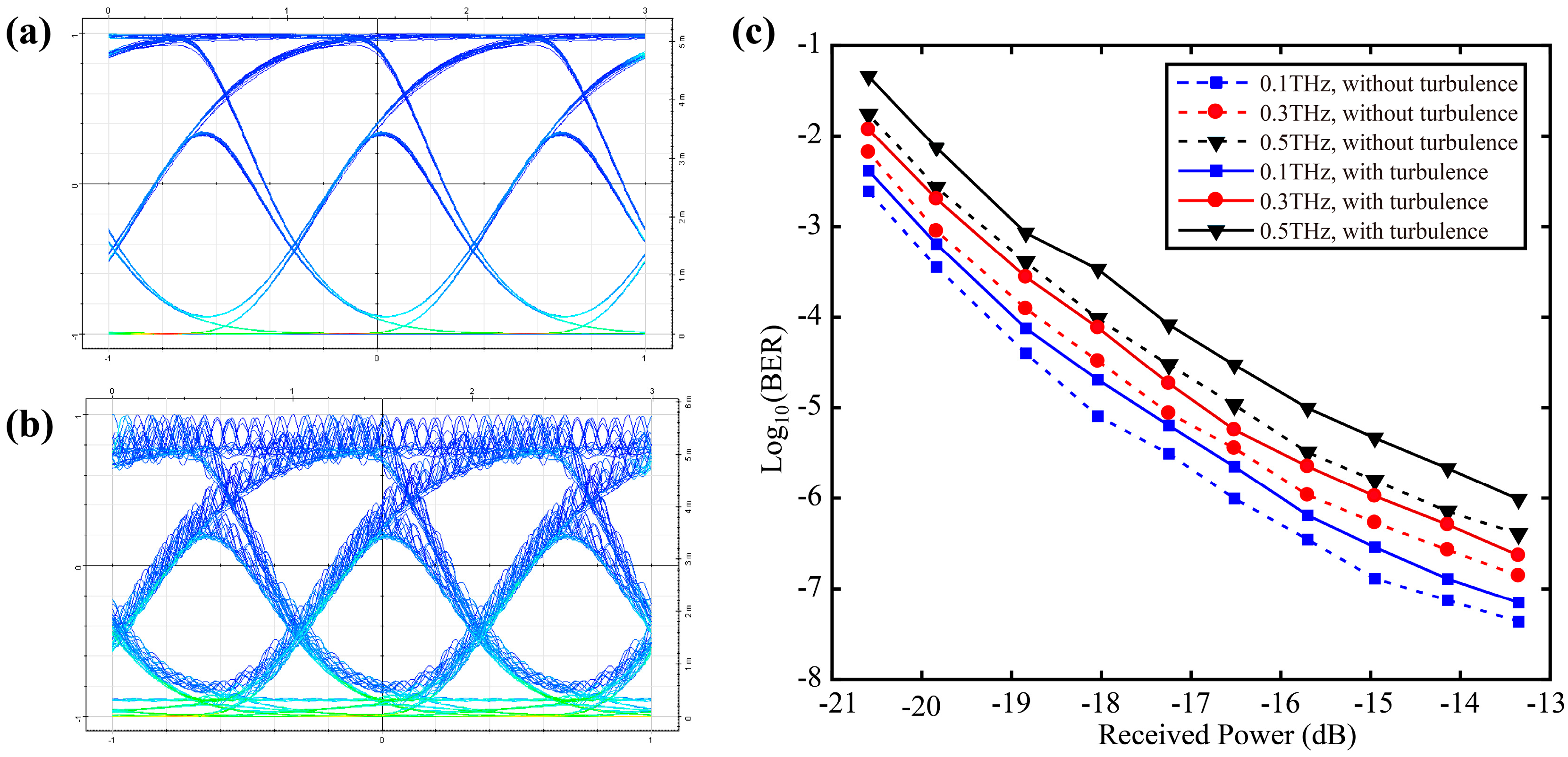
The extent to which the signal is affected depends on the frequency intervals. The eye diagram of the signals at the receiver with the frequency intervals set as 0.1 THz and 0.5 THz are illustrated in Figure 9a,b, respectively. The decrease in frequency intervals resulted in the increase of BER of received signals and deterioration of stability of the waveform. The result of the BER of the transmitted signal is shown in Figure 9c, which shows that the signal quality is better at a frequency interval of 0.5 THz than at 0.3 THz, and the signal quality is better at a frequency interval of 0.3 THz than at 0.1 THz. When the frequency interval descends, the signal quality is significantly affected and the BER gradually increases. Furthermore, at the same frequency interval, a greater turbulence intensity will lead to larger BER of the received signal. Therefore, different frequency intervals or turbulence intensities will affect the BER of received signal even in the same OAM multiplexing link. When the OAM-POL-FDM hybrid multiplexing system is used in the atmospheric turbulence channel, the influence of spectrum efficiency, frequency interval, and turbulence intensity on the hybrid communication system should be considered comprehensively. In order to ensure that the OAM-multiplexed signal can be successfully de-multiplexed, the phase of the vortex beam in the receiver must be completely distinguished. Therefore, the transmission distance cannot exceed the limit of the transmission distance to ensure that the phase can be distinguished under the corresponding turbulence intensity.
4. Conclusions
When the vortex beam is transmitted in free space, the phase of the beam undergoes interference from the random phase error of atmospheric turbulence. We designed a 32-channel hybrid multiplexed communication system and discussed the impact of different turbulence intensities on the communication system by simulation. The spot size and deviation angle of the beam became larger after long-distance transmission. Mutual interference will occur between multiplexed OAM beams under the effect of turbulence. When the OAM beam passes through weak (Cn2 = 10−16 m−2/3) and strong (Cn2 = 10−14 m−2/3) turbulence, 7.2% and 46.8% of the energy leaked into the neighbor OAM mode, respectively. The larger the turbulence intensity, the more scattered the distribution of leaked energy in the adjacent OAM modes. When the OAM modes were l = +4 and l = +8, 3% and 1.6% energy leaked to the adjacent OAM mode and became noise under strong turbulence. Different frequency intervals will have different effects on the hybrid communication system when FDM is adopted. When the frequency interval decreases from 0.5 THz to 0.1 THz, the quality of eye diagrams will deteriorate. When the system transmits information, the performance improvement of BER from strong turbulence (Cn2 = 10−14 m−2/3) to moderate turbulence can reach 0.8776 orders of magnitude, while the BER under weak turbulence (Cn2 = 10−16 m−2/3) outperforms the BER under moderate turbulence (Cn2 = 10−15 m−2/3) for up to 1.86 orders of magnitude. Based on the above results, it can be proven that atmospheric turbulence has a serious impact on the hybrid communication system. When the vortex beam with a topological charge of +8 is transmitted at a distance of 3 km, its phase is completely distorted at a turbulence intensity of Cn2 = 5 × 10⁻¹⁵ m−2/3. Consequently, when the vortex beam of l = +8 is transmitted under the turbulence intensity of Cn2 = 10−15 m−2/3, the distance must be less than 3 km to ensure that the phase can be successfully distinguished. Only when the phase is distinguishable can the signal be separated according to different phases at the receiving end.
Vortex optical communication is an effective method to solve the problem of shortage of spectrum resources. Atmospheric turbulence is an important factor affecting the signal quality of the FSO communication. It is of great significance to study the transmission of a vortex beam in atmospheric turbulence. In this paper, we not only combined FDM with an OAM communication system, but also studied the influences of turbulence on this system. This is an attempt to combine OAM multiplexing technology with the existing FDM communication system. Our new proposed OAM-POL-FDM hybrid multiplexing communication system not only promotes the application of vortex optical communication, but also solves the actual demand, which makes it possible to further increase communication capacity with limited bandwidth.
In our research in the future, we will continue to study the signal transmission of a vortex beam under atmospheric turbulence based on this work. More discussions will be focused on combining new technologies with our systems in order to reduce the effects of turbulence on vortex beam transmission and mitigate crosstalk between different OAM modes.
Author Contributions
Conceptualization, H.L.; Formal analysis and writing, L.Z.; Investigation, Y.H.; Software, H.S.; Validation, Z.W.
Funding
This research was funded by the National Natural Science Foundation of China (NSFC) of Funder, grant nos. 61875057, 61475049.
Conflicts of Interest
The authors declare no conflicts of interest.
References
- Yan, Y.; Xie, G.; Lavery, M.P.; Huang, H.; Ahmed, N.; Bao, C.; Ren, Y.; Cao, Y.; Li, L.; Zhao, Z.; et al. High-capacity millimetre-wave communications with orbital angular momentum multiplexing. Nat. Commun. 2014, 5, 1–9. [Google Scholar] [CrossRef] [PubMed]
- Li, C.; Yang, Q. High capacity optical communication systems using mode division multiplexing. In Proceedings of the Progress in Electromagnetic Research Symposium (PIERS), Shanghai, China, 8–11 August 2016; pp. 4851–4855. [Google Scholar]
- Zhou, X.; Yu, J. Multi-level, multi-dimensional coding for high-speed and high-spectral-efficiency optical transmission. J. Lightwave Technol. 2009, 27, 3641–3653. [Google Scholar] [CrossRef]
- Wada, N.; Puttnam, B.J.; Luis, R.S.; Klaus, W.; Sakaguchi, J.; Mendinueta, J.M.; Awaji, Y.; Shinada, S.; Furukawa, H. Huge capacity spacial division multiplexing transmission and integrated optical switching technologies. Chin. Opt. Lett. 2016, 14, 120004. [Google Scholar] [CrossRef]
- Kobayashi, T.; Sano, A.; Matsuura, A.; Miyamoto, Y.; Ishihara, K. High-order QAM transmission for spectrally-efficient and high-capacity transport. In Proceedings of the OFC/NFOEC, Los Angeles, CA, USA, 4–8 March 2012; pp. 1–3. [Google Scholar]
- Li, L.; Zhang, R.; Zhao, Z.; Xie, G.; Liao, P.; Pang, K.; Song, H.; Liu, C.; Ren, Y.; Labroille, G. High-capacity free-space optical communications between a ground transmitter and a ground receiver via a UAV using multiplexing of multiple orbital-angular-momentum beams. Sci. Rep. 2017, 7, 1–12. [Google Scholar] [CrossRef]
- Wang, J.; Yang, J.-Y.; Fazal, I.M.; Ahmed, N.; Yan, Y.; Huang, H.; Ren, Y.; Yue, Y.; Dolinar, S.; Tur, M. Terabit free-space data transmission employing orbital angular momentum multiplexing. Nat. Photon. 2012, 6, 488–496. [Google Scholar] [CrossRef]
- Wang, J.; Li, S.; Luo, M.; Liu, J.; Zhu, L.; Li, C.; Xie, D.; Yang, Q.; Yu, S.; Sun, J. N-dimentional multiplexing link with 1.036-Pbit/s transmission capacity and 112.6-bit/s/Hz spectral efficiency using OFDM-8QAM signals over 368 WDM pol-muxed 26 OAM modes. In Proceedings of the European Conference on Optical Communication (ECOC), Cannes, France, 21–25 September 2014; pp. 1–3. [Google Scholar]
- Bozinovic, N.; Yue, Y.; Ren, Y.; Tur, M.; Kristensen, P.; Huang, H.; Willner, A.E.; Ramachandran, S. Terabit-scale orbital angular momentum mode division multiplexing in fibers. Science 2013, 340, 1545–1548. [Google Scholar] [CrossRef]
- Wang, J.; Liu, J.; Lv, X.; Zhu, L.; Wang, D.; Li, S.; Wang, A.; Zhao, Y.; Long, Y.; Du, J. Ultra-high 435-bit/s/Hz spectral efficiency using N-dimentional multiplexing and modulation link with pol-muxed 52 orbital angular momentum (OAM) modes carrying Nyquist 32-QAM signals. In Proceedings of the European Conference on Optical Communication (ECOC), Valencia, Spain, 27 September–1 October 2015; pp. 1–3. [Google Scholar]
- Wang, J.; Li, S.; Li, C.; Zhu, L.; Gui, C.; Xie, D.; Qiu, Y.; Yang, Q.; Yu, S. Ultra-high 230-bit/s/Hz spectral efficiency using OFDM/OQAM 64-QAM signals over pol-muxed 22 orbital angular momentum (OAM) modes. In Proceedings of the OFC 2014, San Francisco, CA, USA, 9–13 March 2014; pp. 1–3. [Google Scholar]
- Shen, Y.; Wang, X.; Xie, Z.; Min, C.; Fu, X.; Liu, Q.; Gong, M.; Yuan, X. Optical vortices 30 years on: OAM manipulation from topological charge to multiple singularities. Light Sci. Appl. 2019, 8, 1–29. [Google Scholar] [CrossRef]
- Zheng, D.; Li, Y.; Zhou, H.; Bian, Y.; Yang, C.; Li, W.; Qiu, J.; Guo, H.; Hong, X.; Zuo, Y. Performance enhancement of free-space optical communications under atmospheric turbulence using modes diversity coherent receipt. Opt. Express 2018, 26, 28879–28890. [Google Scholar] [CrossRef]
- Qu, Z.; Djordjevic, I.B. 500 Gb/s free-space optical transmission over strong atmospheric turbulence channels. Opt. Lett. 2016, 41, 3285–3288. [Google Scholar] [CrossRef]
- Yousif, B.B.; Elsayed, E.E. Performance Enhancement of an Orbital-Angular-Momentum-Multiplexed Free-Space Optical Link Under Atmospheric Turbulence Effects Using Spatial-Mode Multiplexing and Hybrid Diversity Based on Adaptive MIMO Equalization. IEEE Access 2019, 7, 84401–84412. [Google Scholar] [CrossRef]
- Xie, Z.; Gao, S.; Lei, T.; Feng, S.; Zhang, Y.; Li, F.; Zhang, J.; Li, Z.; Yuan, X. Integrated (de) multiplexer for orbital angular momentum fiber communication. Photonics Res. 2018, 6, 743–749. [Google Scholar] [CrossRef]
- Oubei, H.M.; Duran, J.R.; Janjua, B.; Wang, H.-Y.; Tsai, C.-T.; Chi, Y.-C.; Ng, T.K.; Kuo, H.-C.; He, J.-H.; Alouini, M.-S. 4.8 Gbit/s 16-QAM-OFDM transmission based on compact 450-nm laser for underwater wireless optical communication. Opt. Express 2015, 23, 23302–23309. [Google Scholar] [CrossRef] [PubMed]
- Huang, H.; Xie, G.; Yan, Y.; Ahmed, N.; Ren, Y.; Yue, Y.; Rogawski, D.; Tur, M.; Erkmen, B.; Birnbaum, K. 100 Tbit/s free-space data link using orbital angular momentum mode division multiplexing combined with wavelength division multiplexing. In Proceedings of the Optical Fiber Communication Conference and Exposition and the National Fiber Optic Engineers Conference (OFC/NFOEC), Anaheim, CA, USA, 17–21 March 2013; pp. 1–3. [Google Scholar]
- Li, S.; Chen, S.; Gao, C.; Willner, A.E.; Wang, J. Atmospheric turbulence compensation in orbital angular momentum communications: Advances and perspectives. Opt. Commun. 2018, 408, 68–81. [Google Scholar] [CrossRef]
- Allen, L.; Beijersbergen, M.W.; Spreeuw, R.; Woerdman, J. Orbital angular momentum of light and the transformation of Laguerre-Gaussian laser modes. Phys. Rev. A 1992, 45, 8185–8190. [Google Scholar] [CrossRef] [PubMed]
- Desyatnikov, A.S.; Torner, L.; Kivshar, Y.S. Optical vortices and vortex solitons. arXiv 2005, arXiv:nlin/0501026. [Google Scholar]
- Rozas, D.; Sacks, Z.; Swartzlander, G., Jr. Experimental observation of fluidlike motion of optical vortices. Phys. Rev. Lett. 1997, 79, 3399–3402. [Google Scholar] [CrossRef]
- Tatarski, V.I. Wave Propagation in a Turbulent Medium; Dover Publications Inc.: New York, NY, USA, 2016. [Google Scholar]
- Fu, S.; Gao, C. Influences of atmospheric turbulence effects on the orbital angular momentum spectra of vortex beams. Photonics Res. 2016, 4, B1–B4. [Google Scholar] [CrossRef]
- Nye, J.F. Natural Focusing and the Fine Structure of Light; Institute of Physics and the Physical Society: London, UK, 1999. [Google Scholar]
- Zhang, H.; Mao, B.; Han, Y.; Wang, Z.; Yue, Y.; Liu, Y. Generation of orbital angular momentum modes using fiber systems. Appl. Sci. 2019, 9, 1033. [Google Scholar] [CrossRef]
- Qu, Z.; Djordjevic, I. Orbital angular momentum multiplexed free-space optical communication systems based on coded modulation. Appl. Sci. 2018, 8, 2179. [Google Scholar] [CrossRef]
- Padgett, M.J.; Miatto, F.M.; Lavery, M.P.; Zeilinger, A.; Boyd, R.W. Divergence of an orbital-angular-momentum-carrying beam upon propagation. New J. Phys. 2015, 17, 1–6. [Google Scholar] [CrossRef]
- Zhao, S.; Leach, J.; Gong, L.; Ding, J.; Zheng, B. Aberration corrections for free-space optical communications in atmosphere turbulence using orbital angular momentum states. Opt. Express 2012, 20, 452–461. [Google Scholar] [CrossRef] [PubMed]
- Anguita, J.A.; Neifeld, M.A.; Vasic, B.V. Turbulence-induced channel crosstalk in an orbital angular momentum-multiplexed free-space optical link. Appl. Opt. 2008, 47, 2414–2429. [Google Scholar] [CrossRef] [PubMed]
- Pors, B.-J.; Monken, C.; Eliel, E.R.; Woerdman, J. Transport of orbital-angular-momentum entanglement through a turbulent atmosphere. Opt. Express 2011, 19, 6671–6683. [Google Scholar] [CrossRef] [PubMed]
- Lavery, M.P.; Heim, B.; Peuntinger, C.; Magaña-Loaiza, O.S.; Karimi, E.; Bauer, T.; Banzer, P.; Marquardt, C.; Willner, A.E.; Boyd, R.W. Study of turbulence induced orbital angular momentum channel crosstalk in a 1.6 km free-space optical link. In Proceedings of the CLEO: Science and Innovations, San Jose, CA, USA, 10–15 May 2015; p. STu1L. 4. [Google Scholar]
- Indebetouw, G. Optical Vortices and Their Propagation. J. Mod. Opt. 1993, 40, 73–87. [Google Scholar] [CrossRef]
- Ren, Y.; Huang, H.; Xie, G.; Ahmed, N.; Yan, Y.; Erkmen, B.I.; Chandrasekaran, N.; Lavery, M.P.; Steinhoff, N.K.; Tur, M. Atmospheric turbulence effects on the performance of a free space optical link employing orbital angular momentum multiplexing. Opt. Lett. 2013, 38, 4062–4065. [Google Scholar] [CrossRef] [PubMed]
Figure 1.
Schematic diagram revealing the calculation method of the vortex beam’s topological charge. (a) Phase distribution under weak turbulence. (b) Phase distribution under strong turbulence.
Figure 1.
Schematic diagram revealing the calculation method of the vortex beam’s topological charge. (a) Phase distribution under weak turbulence. (b) Phase distribution under strong turbulence.

Figure 2.
The working principle of the 32-channel orbital angular momentum (OAM) multiplexing communication system. The OAM beam carrying the signal is multiplexed, and every four beams are combined into one beam. After polarization multiplexing, one beam is combined from every eight (4 × 2) beams. Next, the laser is transmitted through the atmospheric turbulence channel. At the receiver, the frequency division de-multiplexing, the polarization de-multiplexing, and the OAM de-multiplexing are sequentially performed to separate the signals. Finally, detection and decoding are implemented. OAM: orbital angular momentum; FSO: free space optical.

Figure 3.
(a) Spot size distribution of the vortex beam of l = +4 under different transmission distances. (b) Comparison of different deviation angles of beam under different transmission distances.
Figure 3.
(a) Spot size distribution of the vortex beam of l = +4 under different transmission distances. (b) Comparison of different deviation angles of beam under different transmission distances.

Figure 4.
Distributions of intensity and phase of a vortex beam with a topological charge of l = +8 at different transmission distances under a turbulence intensity of Cn2 = 10−15 m−2/3. The intensity distribution becomes more dispersed and the phase distortion becomes more apparent as the transmission distance increases.

Figure 5.
Optical intensity and phase distribution of the vortex beam after transmission through different turbulence intensities. Here, the topological charge of the vortex beam is l = +8 and the transmission distance is 3 km. Turbulence intensity varies from weak turbulence (Cn2 = 10−16 m−2/3) to strong turbulence (Cn2 = 10−13 m−2/3).

Figure 6.
The distribution of intensity and phase of the vortex beam with different topological charges. Turbulence intensity is Cn2 = 5 × 10⁻¹⁵ m−2/3 and transmission distance is 2 km.
Figure 6.
The distribution of intensity and phase of the vortex beam with different topological charges. Turbulence intensity is Cn2 = 5 × 10⁻¹⁵ m−2/3 and transmission distance is 2 km.

Figure 7.
Contrast of signal crosstalk and comparisons of bit error rate (BER) under different turbulence intensities. (a,b) Single OAM mode distribution of a channel at the transmitter and that without turbulence. (c,d) Comparison of mode crosstalk in the case of strong turbulence (Cn2 = 10−14 m−2/3) and weak turbulence (Cn2 = 10−16 m−2/3). (e,f) Two-OAM modes distribution at the transmitter and that without turbulence. (g,h) Superposition of different OAM modes under strong turbulence and weak turbulence. (i) Comparison of BER of received signals. BER: bit error rate.

Figure 8.
The spectral distribution of the 32-channel OAM hybrid multiplexing communication system. The beam is divided into four different frequency ranges after FDM. The intervals between the four frequencies were 0.1 THz, 0.3 THz, and 0.5 THz, respectively.
Figure 8.
The spectral distribution of the 32-channel OAM hybrid multiplexing communication system. The beam is divided into four different frequency ranges after FDM. The intervals between the four frequencies were 0.1 THz, 0.3 THz, and 0.5 THz, respectively.

Figure 9.
(a) Eye diagram of the received signal at a frequency interval of 0.5 THz. (b) Eye diagram of received signal at a frequency interval of 0.1 THz. (c) BER of the received signal at different signal intervals under weak turbulence (Cn2 = 10−16 m−2/3) and without turbulence.
Figure 9.
(a) Eye diagram of the received signal at a frequency interval of 0.5 THz. (b) Eye diagram of received signal at a frequency interval of 0.1 THz. (c) BER of the received signal at different signal intervals under weak turbulence (Cn2 = 10−16 m−2/3) and without turbulence.

© 2019 by the authors. Licensee MDPI, Basel, Switzerland. This article is an open access article distributed under the terms and conditions of the Creative Commons Attribution (CC BY) license (http://creativecommons.org/licenses/by/4.0/).
Share and Cite
MDPI and ACS Style
Zhao, L.; Liu, H.; Hao, Y.; Sun, H.; Wei, Z. Effects of Atmospheric Turbulence on OAM-POL-FDM Hybrid Multiplexing Communication System. Appl. Sci. 2019, 9, 5063. https://doi.org/10.3390/app9235063
AMA Style
Zhao L, Liu H, Hao Y, Sun H, Wei Z. Effects of Atmospheric Turbulence on OAM-POL-FDM Hybrid Multiplexing Communication System. Applied Sciences. 2019; 9(23):5063. https://doi.org/10.3390/app9235063
Chicago/Turabian StyleZhao, Lin, Hongzhan Liu, Yuan Hao, Haoying Sun, and Zhongchao Wei. 2019. "Effects of Atmospheric Turbulence on OAM-POL-FDM Hybrid Multiplexing Communication System" Applied Sciences 9, no. 23: 5063. https://doi.org/10.3390/app9235063
Note that from the first issue of 2016, this journal uses article numbers instead of page numbers. See further details here.