Non-Curing Thermal Interface Materials with Graphene Fillers for Thermal Management of Concentrated Photovoltaic Solar Cells
by
 , , and
Barath Kanna Mahadevan
1,2,3 ,
,
Sahar Naghibi
2,3,
Fariborz Kargar
1,2,* and
Alexander A. Balandin
1,2,3,* 1
Nano-Device Laboratory (NDL), Department of Electrical and Computer Engineering, University of California—Riverside, Riverside, CA 92521, USA
2
Phonon Optimized Engineered Materials (POEM) Center, Bourns College of Engineering, University of California—Riverside, Riverside, CA 92521, USA
3
Materials Science and Engineering Program, University of California—Riverside, Riverside, CA 92521, USA
*
Authors to whom correspondence should be addressed.
C 2020, 6(1), 2; https://doi.org/10.3390/c6010002
Submission received: 18 November 2019
/
Revised: 10 December 2019
/
Accepted: 19 December 2019
/
Published: 22 December 2019
(This article belongs to the Special Issue Surface Modification of Carbons)
Abstract
:Temperature rise in multi-junction solar cells reduces their efficiency and shortens their lifetime. We report the results of the feasibility study of passive thermal management of concentrated multi-junction solar cells with the non-curing graphene-enhanced thermal interface materials. Using an inexpensive, scalable technique, graphene and few-layer graphene fillers were incorporated in the non-curing mineral oil matrix, with the filler concentration of up to 40 wt% and applied as the thermal interface material between the solar cell and the heat sink. The performance parameters of the solar cells were tested using an industry-standard solar simulator with concentrated light illumination at 70× and 200× suns. It was found that the non-curing graphene-enhanced thermal interface material substantially reduces the temperature rise in the solar cell and improves its open-circuit voltage. The decrease in the maximum temperature rise enhances the solar cell performance compared to that with the commercial non-cured thermal interface material. The obtained results are important for the development of the thermal management technologies for the next generation of photovoltaic solar cells.
1. Introduction
Due to increasing energy demands and depletion of non-renewable energy resources, there is an increase in research activities on efficiently harnessing energy from renewable sources like solar and wind. Solar energy is a promising candidate for a sustainable energy source owing to its clean, abundant, accessible, and affordable nature. Photovoltaic (PV) energy generation allowing for direct energy conversion of the sun power to electricity has attracted a lot of interest from both scientific and practical points of view [1,2,3,4]. The research and development activities have been taking place in both traditional and advanced PV solar cell technologies, including silicon, multi-junction, dye-sensitized, and perovskite solar cells. Currently, crystalline silicon solar cells occupy about 90% of the market of the commercially available solar cells and have the maximum power conversion efficiency (PCE) of about 26% while the remaining energy is converted into heat within the solar cell structure [5,6,7,8,9,10].
The multi-junction solar cells with concentrators have an efficiency of more than 40%, and they are the highest efficiency PV cell technology known. The multi-junction PV cells are formed by stacking multiple layers of solar cells with the range of the band gap energies, mostly direct band gap, resulting in higher PCE and absorption coefficient [11,12,13,14,15]. Currently, a six-junction (AlGaInP/AlGaAs/GaAs/GaInAs(3)) concentrator solar cell has the maximum power conversion efficiency of 47.1% at 143× suns illumination (1 sun power = 1 kW/m2) [16,17]. Though multi-junction solar cell technology has been proven to be highly efficient compared to the conventional Si solar cells, thermal management of excess heat generated within the cell presents a major problem [18,19,20]. Due to concentrated light in a small area and multilayered structure of the solar cell, energy absorption is increased, resulting in a significant rise in the solar cell operating temperature.
It is known that under intensive solar irradiation, the polycrystalline and monocrystalline Si solar cells can reach temperatures of 40 °C to 65 °C leading to efficiency loss of 0.35–0.5% per unit K temperature rise [21,22,23,24]. For these reasons, the temperature effects on the performance of conventional and multi-junction solar cells have been a subject of many studies [25,26,27,28]. It is important to extract the dissipated heat from the multi-junction solar cell, since the increase in solar cell temperature, in the short term, can lead to power conversion efficiency loss and, in the long-term, degradation of the lifetime of the solar cell [29,30,31,32,33]. The most commonly used methods for extraction of heat from an electrical system are active cooling, phase change material (PCMs) for heat storage [34,35,36,37,38], and passive cooling [39,40].
The active cooling method utilizes forced convection, which relies on external machines to enhance heat dissipation. This method includes the use of fans to circulate air and pumps for circulating liquids along with utilization of thermoelectric coolers to extract excess heat from the solar panel. Due to the non-uniform heat distribution and increased capital cost for additional mechanisms involved, active cooling methods are usually not the best solution for solar cell applications [41]. The thermal management with PCMs involves storing the excess heat generated by the system and slowing releasing it to the environment. While attractive from the cost considerations, PCMs also have problems owing to their rather low thermal conductivity [42,43]. The passive cooling methods use only natural convection and no external energy for heat extraction. Most solar cells use passive cooling technologies like heat sinks, heat spreaders, and heat pipes for excess heat dissipation since they are cost-effective. High thermal resistance between the back surface of the solar cell and heat sink can limit the amount of heat transferred from the solar cell to the heat sink [44]. This resistance to heat flow is caused by surface imperfections and associated with air gaps between the attached surfaces. Since air is a poor conductor of heat, there is a need to replace it with a higher thermal conductivity material for improved heat transfer. Thermal interface materials (TIMs) can be used to improve the thermal conductivity of the interface layer, facilitating the heat transfer from the solar cell to the heat sink [45,46,47,48,49,50,51]. We also need to note that interfacial thermal resistance exists between TIM and the connecting surfaces due to the mismatch of the acoustic phonon properties [52].
In this paper, we report the results of the feasibility study of thermal management of multi-junction solar cells under 70× and 200× suns illumination with non-curing graphene-enhanced TIMs. Non-curing TIMs are substantially different from more conventional epoxy-based curing TIMs since they do not solidify completely and thus, do not suffer from developments of cracks due to the differences in the thermal expansion coefficients. We demonstrate that the detrimental effects of temperature on the performance of multi-junction solar cells can be substantially reduced by using non-curing TIMs with incorporated graphene and few-layer graphene (FLG) fillers [53,54,55]. Graphene, due to its exceptional intrinsic high thermal conductivity and excellent compatibility with polymeric matrices is used as fillers to enhance the low thermal conductivity of the base polymer. The room-temperature intrinsic values of thermal conductivity of graphene range from ~2000 to ~5000 W/mK, depending on the size and quality of the graphene samples [56,57,58,59,60,61,62,63]. It has been verified that decreasing the lateral dimension of the graphene layers reduces its thermal conductivity. Therefore, graphene flakes with micrometer-scale lateral dimensions are preferred over graphene nanoparticles for thermal management applications [54]. In the thermal context, we refer to the mixture of graphene and FLG flakes as “graphene fillers”. While the intrinsic thermal conductivity of FLG is lower than that of single-layer graphene, FLG fillers have the advantages of a larger cross-section for heat transfer. Moreover, they preserve better their thermal properties upon exposure to the matrix material, and experience less bending and rolling during the mixing process with the base polymer matrix.
In our prior research, we have tested commercial TIMs with the addition of low-concentration graphene [64]. The composition of commercial TIMs was not known. In the present study, we use in-house produced non-curing TIMs based on mineral oil with a high concentration of graphene fillers. The limitation of the earlier work was that the high concentration of graphene fillers could not have been achieved in commercial TIMs owing to their higher viscosity. The use of pure mineral oil allows one to reach graphene loadings of 40 wt%. Even higher loadings (>40 wt%) appear, at least at present, not practical since excessive graphene loading can result in the formation of air gaps, agglomeration of graphene fillers, and uneven dispersion of the fillers [65]. Optimization of the size and thickness of graphene—FLG fillers can lead to further improvements in thermal management applications [66,67,68,69,70,71,72,73].
2. Material Preparation and Characterization
The non-cured TIMs were prepared by homogenous mixing of mineral oil with graphene fillers. The graphene source (xGnP®H-25, XG-Sciences Inc., Lansing, MI, USA) had FLG flakes with vendor-defined thicknesses of approximately 6 to 8 nm, a typical surface area of 50 to 80 m2/g, and an average filler diameter of 25 µm. The pre-determined amounts of graphene were measured and added to acetone, creating a suspension, allowing for facile mixing of the graphene filler with mineral oil. The weight percentage of graphene needed to be mixed with mineral oil was calculated as , where and are the weights of graphene fillers and mineral oil, respectively. The samples were then sheer mixed and decanted to remove the excess acetone with the graphene-enhanced TIM remaining.
The thermal conductivity of the resulting non-curing mineral-oil based TIMs with graphene fillers was measured using TIM Tester (LW-9389-TIM Tester, Long Win North America Laboratory, Livermore, CA, USA). During the measurements, the TIM layer thickness and temperature were carefully controlled by the TIM tester software. The thermal resistance of each sample was measured at room temperature at different thicknesses and its bulk thermal conductivity was extracted. Table 1 shows the results of thermal conductivity measurements of non-curing TIMs with varying weight concentrations of graphene and a reference commercial TIM (Ice Fusion, Cooler Master Technology Inc., Taiwan, China). The increase in graphene concentration results in higher thermal conductivity. Thermal conductivity of 6.74 W/mK was measured for the mineral oil-based TIM with 40 wt% graphene filler loading. For comparison, the thermal conductivity of the commercial TIM was only 1.34 W/mK. The addition of only 10 wt% of graphene to mineral oil results in TIM with a higher thermal conductivity than that of measured for the commercial TIM. The thermal conductivity of mineral oil with 40 wt% graphene fillers revealed the thermal conductivity of ~5 times more than that of the commercial TIM.
3. Solar Cell Testing Procedures
The developed non-cured TIMs with graphene fillers and reference commercial TIM and mineral oil base material were applied uniformly between the InGaP/InGaAs/Ge concentrator triple-junction solar cell (Cell type 3C42C, Azur Space, Heilbronn, Germany) and a heat sink to understand and compare the effects of graphene-based TIMs on the performance of multi-junction solar cells (see Supplemental Materials). The total thermal resistance between the solar cell and the heat sink, , depends on various factors, including TIM thermal conductivity (), thermal contact resistance between the TIM layer and the two metal surfaces ( and ), and the bond layer thickness (), i.e., the distance between the two surfaces [64]. The thermal resistance is related to the above factors by the following equation [53,54,74]:
The TIMs were uniformly applied on the back surface of the multi-junction solar cells. Plastic shims with predefined thickness were used to accurately control the thickness of the TIM layer. For practical application purposes, BLT of the TIM layer was fixed at 54 μm, keeping in mind that large BLT increases the total thermal resistance. The multi-junction solar cell with various TIMs was tested using a solar simulator (Sol1A Class ABA, Newport Corp., Irvine, CA, USA). The solar simulator uses a xenon lamp of 1000 W to generate a 15 × 15 cm2 size beam with a tunable output irradiation power of up to 1 kW/m2 (approximately 1 sun power). The light emitted by the xenon lamp passes through a multiple correction filter and collimating lens to produce an output light beam with angular divergence of ~0.5° in order to imitate sunlight when it reaches earth. A convex lens along with a pyramidal secondary optical element (SOE) used to focus and collect the light beams on the multi-junction solar cell. The distance between the lens, SOE, and the solar cell were carefully aligned to achieve maximum focus, and a light concentration of 70× and 200× suns was achieved on the surface of the solar cell by changing the power input of xenon lamp in the solar simulator. Figure 1 shows the schematic of the experimental setup. Once the multi-junction solar cell is illuminated by the solar simulator, the open-circuit voltage was measured by a multi-meter (Fluke 287, Fluke Corp., Everett, WA, USA). The time-transient temperature of the solar cell was measured using a multichannel temperature logger (AT4516 Multi-channel temperature meter, Applent Instruments Inc., Jiangsu Province, China) every 5 s for 30 min under 70× suns illumination and for 20 min under 200× suns illumination until the solar cell reached the steady-state temperature condition. The same solar cell was used for all the experiments for the consistency of results. The actual experimental setup is shown in Supplementary Materials Figures S1 and S2.
4. Results and Discussion
Before assessing the efficiency of the thermal management with TIMs, we verified the solar cell performance. The short-circuit current density, , open-circuit voltage, , fill factor, , and power conversion efficiency, , are the major characteristics of the PV cell performance [75,76]. The open-circuit voltage is affected by the increase in temperature due to the following diode factors: Ideality factor, n, saturation current density, , series resistance, , and shunt resistance, , of the solar cell. The values of , and increases slightly with an increase in temperature but does not affect the efficiency of the cell much [77]. From the other side, is a material dependent factor, which changes drastically with increase in temperature, affecting the value and, eventually, the PV conversion efficiency [77,78,79,80]:
where, is a constant number, is the bandgap of the material, is the absolute temperature of the solar cell, is the Boltzmann’s constant, is the photo-generated current density, and is the electron charge.
As the temperature increases, the effective bandgap of the solar cell decreases [81], which increases the number of photo-generated electrons. As decreases and temperature, , increases the effective saturation current density, , also increases (see Equation (2)). The current density-voltage characteristic of a p-n junction solar cell is given by Equation (3). The open-circuit voltage is the maximum voltage obtained from the solar cell, i.e., in Equation (4) is obtained by equating in the Equation (3) and [82]:
Since increases with increase in temperature, the effective open-circuit voltage, of the solar cell decreases drastically. The fill factor can be defined as the ratio of the maximum power output, , to the product of the open-circuit voltage and short-circuit current density (see Equation (5)). The fill factor ranges from 0.7 to 0.88 for the multi-junction solar cells [83]. The efficiency of the solar cell () is defined as the ratio of the maximum output power to the incident irradiation (Equation (6)). Since and do not change much with temperature, and the power of the incident irradiation is constant and strongly decreases with temperature rise, the efficiency of the solar cell is reduced as the temperature rises up (see Equation (6)).
Guided by the conventional theory summarized above, we investigated the PV cell performance parameters with different TIMs. The black curve in Figure 2 shows the short-circuit current corresponding to the illuminations of × suns for the PV cell attached to the heat sink with the graphene enhanced TIM of 40 wt% filler loading. As the distance between the solar cell and the focusing lens changes slightly, some portion of the focused light falls off the inlet aperture of the SOE and hence, the illumination on the top surface of the cell decreases. The blue and red curves in Figure 2 demonstrates the for smaller illuminations of . As expected, the short-circuit current is larger for the optimum concentrated illumination. The inset in Figure 2 shows the variation of the with time at 70× suns irradiation. One can see that there is a little increase in the values with time, i.e., an increase in temperature. The increase in is insignificant, and it does not lead to any observable change in the efficiency of the solar cell. These experimental observations are in line with the theory described above.
As the next step, we measured the open-circuit voltage of the concentrated PV solar cells attached to the heat sink with different TIMs under fixed concentrated light illumination of 70× and 200× suns. As predicted by the theory, the major contribution to the power loss in the solar cell was due to the decrease in . Figure 3 shows the open-circuit voltage as a function of the time of measurement. One can see that rapidly decreases and then saturates, as the solar cell reaches to the steady state condition, in all examined cases. The decrease in the open-circuit voltage is the largest in the case of the solar cell attached to the heat sink with the mineral oil base material. The use of commercial non-cured TIM allows one to improve the performance. However, there is a major improvement in the solar cell performance when the in-house non-cured TIMs with graphene fillers are utilized. We observed a maximum improvement of a 44% reduction in the decrease in values of the PV solar cells when using 40 wt% graphene fillers in mineral oil as compared to commercial TIM at the saturated state after 20 min of 200× suns illumination.
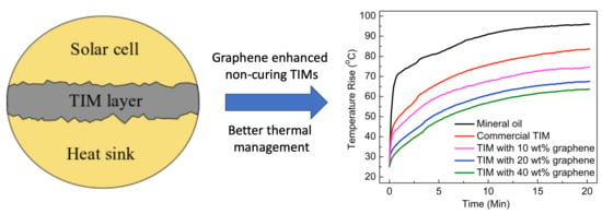
Finally, we monitored the temperature rise of the PV solar cells attached to the heat sink with different TIMs at 70× and 200× suns illuminations. The measurement of the temperature of the solar cell complements the measurement of the thermal conductivity, i.e., the lower thermal conductivity of TIM results in higher solar cell temperature due to worse heat transfer from the solar cell to the heat sink. The results of the measurements are presented in Figure 4. The temperature rise in the solar cell was reduced by 34% using the non-cured graphene-enhanced TIM with 40 wt% graphene loading as compared to that of the commercial non-cured TIM under 200× suns illumination. The temperature increased from 25 to 84 °C when the commercial TIM was applied. A temperature increase of ~39 °C, from 25 to 64 °C, was recorded when the non-cured TIMs with 40 wt% graphene was used. One should keep in mind that commercial non-cured TIMs have a large variety of fillers with optimized sizes, composition, and concentrations to deliver the best performance. The tested in-house TIM consisted only of the mineral oil base and graphene mixture. Optimization of graphene filler size, thickness, and the use of additional fillers can further improve the performance of non-cured graphene-enhanced TIMs.
The measured data for the temperature of the PV cell and the open-circuit voltage are specific to the experimental conditions, i.e., multi-junction solar cell design, heat sink design, BLT of the TIM, the concentration of light and others. The results may vary depending on the cell design and other parameters. However, the present study proves that the application of the non-curing graphene-enhanced TIMs at the interfaces of the solar cell and the heat sink significantly enhances the heat dissipation to the environment, which, in turn, significantly decreases the solar cell’s operating temperature. As a result, a major improvement in the PV solar cell performance is achieved with the use of non-cured graphene-enhanced TIMs. One should also note that the use of non-curing TIMs instead of epoxy-based curing TIMs can help to avoid cracks appearing due to the differences in the thermal expansion coefficient between the TIM layer and the solar cell—heat sink surfaces.
5. Conclusions
We report the results of the feasibility study of thermal management of multi-junction solar cells with graphene-enhanced non-curing thermal interface materials. Using an inexpensive scalable technique, graphene and few-layer graphene fillers were incorporated in the non-curing mineral oil matrix, with the concentration of up to 40 wt%. The thermal interface material was applied between a solar cell and a heat sink to facilitate heat removal. The efficiency of the solar cell was tested using an industry-standard solar simulator with concentrated light illumination at 70× suns. It was found that the non-curing graphene-enhanced thermal interface material substantially reduces the temperature rise in the solar cell and improves the open-circuit voltage. The use of graphene fillers allows to achieve significant improvement in solar cell performance compared to the commercial non-cured thermal interface material. The decrease in values was reduced up to 44% using graphene filler TIMs compared to the commercial TIM under 200× suns illumination. This was achieved due to the reduction in solar cell temperature rise by 34% when graphene enhanced TIMs were utilized. The obtained results are important for the development of the thermal management technologies for the next generation of photovoltaic solar cells.
Supplementary Materials
The following are available online at https://www.mdpi.com/2311-5629/6/1/2/s1, Figure S1: (a) Solar cell cleaned with acetone, (b) TIM uniformly applied on the back surface, (c) shims attached to the edges of solar cell, and (d) solar cell bolted to the heat sink with SOE on top, Figure S2: Actual experimental setup working at 70 suns illumination with multi-meter recording the open circuit voltage.
Author Contributions
A.A.B. and F.K. planned and coordinated the project. B.K.M. conducted solar tests with different TIMs and assisted in TIM preparation and thermal measurements. S.N. prepared TIMs with graphene and conducted thermal conductivity measurements. All authors have read and agreed to the published version of the manuscript.
Funding
This work was supported, in part, by the UC—National Laboratory Collaborative Research and Training Program—University of California Research Initiatives LFR-17-477237.
Conflicts of Interest
The authors declare no conflicts of interest.
References
- Ponce, F.A. Novel Semiconductors For Sustainable Solar Energy Technologies. J. Phys. Conf. Ser. 2019, 1173, 012001. [Google Scholar] [CrossRef]
- Tyagi, H.; Agarwal, A.K.; Chakraborty, P.R.; Powar, S. Introduction to Advances in Solar Energy Research, 1st ed.; Springer Neture Singapore: Singapore, 2019; pp. 3–11. [Google Scholar]
- Oaneill, M.; McDanal, A.J.; Piszczor, M.; Peshek, T.; Myers, M.; McPheeters, C.; Steinfeldt, J.; Heintz, B.; Sharps, P.; Puglia, M.; et al. Advanced Development of Space Photovoltaic Concentrators Using Robust Lenses, Multi-Junction Cells, Graphene Radiators. In Proceedings of the 2018 IEEE 7th World Conference Photovoltaic Energy Conversion, Waikoloa Village, HI, USA, 10–15 June 2018. [Google Scholar] [CrossRef]
- Yang, D.; Yang, R.; Priya, S.; Liu, S. (Frank) Recent Advances in Flexible Perovskite Solar Cells: Fabrication and Applications. Angew. Chem. Int. Ed. 2019, 58, 4466–4483. [Google Scholar] [CrossRef] [PubMed]
- Xue, Q.; Xia, R.; Brabec, C.J.; Yip, H.L. Recent Advances in Semi-Transparent Polymer and Perovskite Solar Cells for Power Generating Window Applications. Energy Environ. Sci. 2018, 11, 1688–1709. [Google Scholar] [CrossRef]
- Rodríguez-Seco, C.; Cabau, L.; Vidal-Ferran, A.; Palomares, E. Advances in the Synthesis of Small Molecules as Hole Transport Materials for Lead Halide Perovskite Solar Cells. Acc. Chem. Res. 2018, 51, 869–880. [Google Scholar] [CrossRef]
- Di Carlo Rasi, D.; Janssen, R.A.J. Advances in Solution-Processed Multijunction Organic Solar Cells. Adv. Mater. 2019, 31. [Google Scholar] [CrossRef]
- Lu, L.; Zheng, T.; Wu, Q.; Schneider, A.M.; Zhao, D.; Yu, L. Recent Advances in Bulk Heterojunction Polymer Solar Cells. Chem. Rev. 2015, 115, 12666–12731. [Google Scholar] [CrossRef]
- Zuo, C.; Bolink, H.J.; Han, H.; Huang, J.; Cahen, D.; Ding, L. Advances in Perovskite Solar Cells. Adv. Sci. 2016, 3, 1–16. [Google Scholar] [CrossRef]
- Yu, M.; Long, Y.Z.; Sun, B.; Fan, Z. Recent Advances in Solar Cells Based on One-Dimensional Nanostructure Arrays. Nanoscale 2012, 4, 2783–2796. [Google Scholar] [CrossRef]
- Gledhill, L.K.M. High Efficiency Multi-Junction Space Solar Cells. In Proceedings of the Space Programs and Technologies Conference, Hunstville, AL, USA, 26–28 September 1995; Volume 6, p. 3540. [Google Scholar]
- King, R.R.; Law, D.C.; Edmondson, K.M.; Fetzer, C.M.; Kinsey, G.S.; Yoon, H.; Sherif, R.A.; Karam, N.H. 40% Efficient Metamorphic GaInP/GaInAs/Ge Multijunction Solar Cells. Appl. Phys. Lett. 2007, 90, 90–93. [Google Scholar] [CrossRef] [Green Version]
- Takamoto, T.; Kaneiwa, M.; Imaizumi, M.; Yamaguchi, M. InGaP/GaAs-Based Multijunction Solar Cells. Prog. Photovolt. Res. Appl. 2005, 13, 495–511. [Google Scholar] [CrossRef]
- Law, D.C.; King, R.R.; Yoon, H.; Archer, M.J.; Boca, A.; Fetzer, C.M.; Mesropian, S.; Isshiki, T.; Haddad, M.; Edmondson, K.M.; et al. Future Technology Pathways of Terrestrial III-V Multijunction Solar Cells for Concentrator Photovoltaic Systems. Sol. Energy Mater. Sol. Cells 2010, 94, 1314–1318. [Google Scholar] [CrossRef]
- Cotal, H.; Fetzer, C.; Boisvert, J.; Kinsey, G.; King, R.; Hebert, P.; Yoon, H.; Karam, N. III-V Multijunction Solar Cells for Concentrating Photovoltaics. Energy Environ. Sci. 2009, 2, 174–192. [Google Scholar] [CrossRef]
- Geisz, J.F.; Steiner, M.A.; Jain, N.; Schulte, K.L.; France, R.M.; McMahon, W.E.; Perl, E.E.; Friedman, D.J. Building a Six-Junction Inverted Metamorphic Concentrator Solar Cell. IEEE J. Photovolt. 2018, 8, 626–632. [Google Scholar] [CrossRef]
- Green, M.A.; Dunlop, E.D.; Levi, D.H.; Hohl-Ebinger, J.; Yoshita, M.; Ho-Baillie, A.W.Y. Solar Cell Efficiency Tables (Version 54). Prog. Photovolt. Res. Appl. 2019, 27, 565–575. [Google Scholar] [CrossRef]
- Du, Y.; Le, N.C.H.; Chen, D.; Chen, H.; Zhu, Y. Thermal Management of Solar Cells Using a Nano-Coated Heat Pipe Plate: An Indoor Experimental Study. Int. J. Energy Res. 2017, 41, 867–876. [Google Scholar] [CrossRef]
- Ciulla, G.; Lo Brano, V.; Moreci, E. Forecasting the Cell Temperature of PV Modules with an Adaptive System. Int. J. Photoenergy 2013, 2013, 10. [Google Scholar] [CrossRef]
- Alonso García, M.C.; Balenzategui, J.L. Estimation of Photovoltaic Module Yearly Temperature and Performance Based on Nominal Operation Cell Temperature Calculations. Renew. Energy 2004, 29, 1997–2010. [Google Scholar] [CrossRef]
- Radziemska, E. The Effect of Temperature on the Power Drop in Crystalline Silicon Solar Cells. Renew. Energy 2003, 28, 1–12. [Google Scholar] [CrossRef]
- Mageed, H.M.A. Temperature Effects on the Electrical Performance of Large Area Multicrystalline Silicon Solar Cells Using the Current Shunt Measuring Technique. Engineering 2010, 2, 888–894. [Google Scholar] [CrossRef]
- Brinkworth, B.J.; Cross, B.M.; Marshall, R.H.; Yang, H. Thermal Regulation of Photovoltaic Cladding. Sol. Energy 1997, 61, 169–178. [Google Scholar] [CrossRef]
- Brinkworth, B.J.; Sandberg, M. Design Procedure for Cooling Ducts to Minimise Efficiency Loss Due to Temperature Rise in PV Arrays. Sol. Energy 2006, 80, 89–103. [Google Scholar] [CrossRef]
- Sadewasser, S.; Salomé, P.M.P.; Rodriguez-Alvarez, H. Materials Efficient Deposition and Heat Management of CuInSe2 Micro-Concentrator Solar Cells. Sol. Energy Mater. Sol. Cells 2017, 159, 496–502. [Google Scholar] [CrossRef]
- Ling, Z.; Zhang, Z.; Shi, G.; Fang, X.; Wang, L.; Gao, X.; Fang, Y.; Xu, T.; Wang, S.; Liu, X. Review on Thermal Management Systems Using Phase Change Materials for Electronic Components, Li-Ion Batteries and Photovoltaic Modules. Renew. Sustain. Energy Rev. 2014, 31, 427–438. [Google Scholar] [CrossRef] [Green Version]
- Mousavi Baygi, S.R.; Sadrameli, S.M. Thermal Management of Photovoltaic Solar Cells Using Polyethylene Glycol1000 (PEG1000) as a Phase Change Material. Therm. Sci. Eng. Prog. 2018, 5, 405–411. [Google Scholar] [CrossRef]
- Radwan, A.; Ookawara, S.; Ahmed, M. Thermal Management of Concentrator Photovoltaic Systems Using Two-Phase Flow Boiling in Double-Layer Microchannel Heat Sinks. Appl. Energy 2019, 241, 404–419. [Google Scholar] [CrossRef]
- Li, D.; Xuan, Y.; Yin, E.; Li, Q. Conversion Efficiency Gain for Concentrated Triple-Junction Solar Cell System Through Thermal Management. Renew. Energy 2018, 126, 960–968. [Google Scholar] [CrossRef]
- Khan, S.A.; Sezer, N.; Ismail, S.; Koç, M. Design, Synthesis and Nucleate Boiling Performance Assessment of Hybrid Micro-Nano Porous Surfaces for Thermal Management of Concentrated Photovoltaics (CPV). Energy Convers. Manag. 2019, 195, 1056–1066. [Google Scholar] [CrossRef]
- Reddy, S.R.; Ebadian, M.A.; Lin, C.X. A review of PV-T systems: Thermal Management and Efficiency with Single Phase Cooling. Int. J. Heat Mass Transf. 2015, 91, 861–871. [Google Scholar] [CrossRef]
- Sun, X.; Silverman, T.J.; Zhou, Z.; Khan, M.R.; Bermel, P.; Alam, M.A. Optics-Based Approach to Thermal Management of Photovoltaics: Selective-Spectral and Radiative Cooling. IEEE J. Photovolt. 2017, 7, 566–574. [Google Scholar] [CrossRef]
- Chauhan, A.; Tyagi, V.V.; Anand, S. Futuristic Approach for Thermal Management in Solar PV/Thermal Systems with Possible Applications. Energy Convers. Manag. 2018, 163, 314–354. [Google Scholar] [CrossRef]
- Rabie, R.; Emam, M.; Ookawara, S.; Ahmed, M. Thermal Management of Concentrator Photovoltaic Systems Using New Configurations of Phase Change Material Heat Sinks. Sol. Energy 2019, 183, 632–652. [Google Scholar] [CrossRef]
- Sharma, S.; Micheli, L.; Chang, W.; Tahir, A.A.; Reddy, K.S.; Mallick, T.K. Nano-Enhanced Phase Change Material for Thermal Management of BICPV. Appl. Energy 2017, 208, 719–733. [Google Scholar] [CrossRef]
- Preet, S. Water and Phase Change Material Based Photovoltaic Thermal Management Systems: A review. Renew. Sustain. Energy Rev. 2018, 82, 791–807. [Google Scholar] [CrossRef]
- Ma, T.; Yang, H.; Zhang, Y.; Lu, L.; Wang, X. Using Phase Change Materials in Photovoltaic Systems for Thermal Regulation and Electrical Efficiency Improvement: A Review and Outlook. Renew. Sustain. Energy Rev. 2015, 43, 1273–1284. [Google Scholar] [CrossRef]
- Browne, M.C.; Norton, B.; McCormack, S.J. Phase Change Materials for Photovoltaic Thermal Management. Renew. Sustain. Energy Rev. 2015, 47, 762–782. [Google Scholar] [CrossRef]
- Du, Y. Advanced Thermal Management of a Solar Cell by a Nano-Coated Heat Pipe Plate: A Thermal Assessment. Energy Convers. Manag. 2017, 134, 70–76. [Google Scholar] [CrossRef]
- Sargunanathan, S.; Elango, A.; Mohideen, S.T. Performance Enhancement of Solar Photovoltaic Cells Using Effective Cooling Methods: A review. Renew. Sustain. Energy Rev. 2016, 64, 382–393. [Google Scholar] [CrossRef]
- Ye, Z.; Li, Q.; Zhu, Q.; Pan, W. The Cooling Technology of Solar Cells Under Concentrated System. In Proceedings of the 2009 IEEE 6th International Power Electronics and Motion Control Conference, Wuhan, China, 17–20 May 2009; Volume 3, pp. 2193–2197. [Google Scholar]
- Hasan, A.; McCormack, S.J.; Huang, M.J.; Norton, B. Evaluation of Phase Change Materials for Thermal Regulation Enhancement of Building Integrated Photovoltaics. Sol. Energy 2010, 84, 1601–1612. [Google Scholar] [CrossRef] [Green Version]
- Huang, M.J.; Eames, P.C.; Norton, B. Phase Change Materials for Limiting Temperature Rise in Building Integrated Photovoltaics. Sol. Energy 2006, 80, 1121–1130. [Google Scholar] [CrossRef]
- Du, D.; Darkwa, J.; Kokogiannakis, G. Thermal Management Systems for Photovoltaics (PV) Installations: A Critical Review. Sol. Energy 2013, 97, 238–254. [Google Scholar] [CrossRef]
- Prasher, R.; Chiu, C.P. Thermal interface materials. Mater. Adv. Packag. Second Ed. 2016, 10, 511–535. [Google Scholar]
- Zhang, K.; Chai, Y.; Yuen, M.M.F.; Xiao, D.G.W.; Chan, P.C.H. Carbon Nanotube Thermal Interface Material for High-Brightness Light-Emitting-Diode Cooling. Nanotechnology 2008, 19, 205706. [Google Scholar] [CrossRef] [PubMed]
- Renteria, J.; Legedza, S.; Salgado, R.; Balandin, M.P.; Ramirez, S.; Saadah, M.; Kargar, F.; Balandin, A.A. Magnetically-Functionalized Self-Aligning Graphene Fillers for High-Efficiency Thermal Management Applications. Mater. Des. 2015, 88, 214–221. [Google Scholar] [CrossRef] [Green Version]
- Malekpour, H.; Chang, K.H.; Chen, J.C.; Lu, C.Y.; Nika, D.L.; Novoselov, K.S.; Balandin, A.A. Thermal Conductivity of Graphene Laminate. Nano Lett. 2014, 14, 5155–5161. [Google Scholar] [CrossRef] [PubMed]
- Yan, Z.; Nika, D.L.; Balandin, A.A. Thermal Properties of Graphene and Few-Layer Graphene: Applications in Electronics. IET Circuits Devices Syst. 2015, 9, 4–12. [Google Scholar] [CrossRef]
- Goli, P.; Legedza, S.; Dhar, A.; Salgado, R.; Renteria, J.; Balandin, A.A. Graphene-Enhanced Hybrid Phase Change Materials for Thermal Management of Li-Ion Batteries. J. Power Sources 2014, 248, 37–43. [Google Scholar] [CrossRef] [Green Version]
- Renteria, J.; Nika, D.; Balandin, A. Graphene Thermal Properties: Applications in Thermal Management and Energy Storage. Appl. Sci. 2014, 4, 525–547. [Google Scholar] [CrossRef] [Green Version]
- Li, X.; Yang, R. Effect of Lattice Mismatch on Phonon Transmission and Interface Thermal Conductance Across Dissimilar Material Interfaces. Phys. Rev. B Condens. Matter Mater. Phys. 2012, 86. [Google Scholar] [CrossRef] [Green Version]
- Shahil, K.M.F.; Balandin, A.A. Thermal Properties of Graphene and Multilayer Graphene: Applications in Thermal Interface Materials. Solid State Commun. 2012, 152, 1331–1340. [Google Scholar] [CrossRef]
- Shahil, K.M.F.; Balandin, A.A. Graphene-Multilayer Graphene Nanocomposites as Highly Efficient Thermal Interface Materials. Nano Lett. 2012, 12, 861–867. [Google Scholar] [CrossRef] [Green Version]
- Goyal, V.; Balandin, A.A. Thermal Properties of the Hybrid Graphene-Metal Nano-Micro-Composites: Applications in Thermal Interface Materials. Appl. Phys. Lett. 2012, 100. [Google Scholar] [CrossRef] [Green Version]
- Nika, D.L.; Balandin, A.A. Phonons and Thermal Transport in Graphene and Graphene-Based Materials. Rep. Prog. Phys. 2017, 80. [Google Scholar] [CrossRef] [PubMed] [Green Version]
- Balandin, A.A.; Nika, D.L.; Ghosh, S.; Pokatilov, E.P. Lattice Thermal Conductivity of Graphene Flakes: Comparison with Bulk Graphite. Appl. Phys. Lett. 2009, 94, 3–5. [Google Scholar]
- Ghosh, S.; Bao, W.; Nika, D.L.; Subrina, S.; Pokatilov, E.P.; Lau, C.N.; Balandin, A.A. Dimensional Crossover of Thermal Transport In Few-Layer Graphene. Nat. Mater. 2010, 9, 555–558. [Google Scholar] [CrossRef]
- Ghosh, S.; Nika, D.L.; Pokatilov, E.P.; Balandin, A.A. Heat Conduction in Graphene: Experimental Study and Theoretical Interpretation. New J. Phys. 2009, 11, 095012. [Google Scholar] [CrossRef]
- Balandin, A.A.; Ghosh, S.; Nika, D.L.; Pokatilov, E.P. Thermal Conduction in Suspended Graphene Layers. Fuller. Nanotub. Carbon Nanostruct. 2010, 18, 474–486. [Google Scholar] [CrossRef]
- Balandin, A.A. Thermal Properties of Graphene and Nanostructured Carbon Materials. Nat. Mater. 2011, 10, 569–581. [Google Scholar] [CrossRef] [Green Version]
- Balandin, A. The Heat Is On: Graphene Applications. IEEE Nanotechnol. Mag. 2011, 5, 15–19. [Google Scholar] [CrossRef]
- Nika, D.L.; Pokatilov, E.P.; Askerov, A.S.; Balandin, A.A. Phonon Thermal Conduction in Graphene: Role of Umklapp and Edge Roughness Scattering. Phys. Rev. B Condens. Matter Mater. Phys. 2009, 79, 1–12. [Google Scholar] [CrossRef] [Green Version]
- Saadah, M.; Hernandez, E.; Balandin, A.A. Thermal Management of Concentrated Multi-Junction Solar Cells with Graphene-Enhanced Thermal Interface Materials. Appl. Sci. 2017, 7, 589. [Google Scholar] [CrossRef] [Green Version]
- McNamara, A.J.; Joshi, Y.; Zhang, Z.M. Characterization of Nanostructured Thermal Interface Materials—A Review. Int. J. Therm. Sci. 2012, 62, 2–11. [Google Scholar] [CrossRef]
- Lv, P.; Tan, X.W.; Yu, K.H.; Zheng, R.L.; Zheng, J.J.; Wei, W. Super-Elastic Graphene/Carbon Nanotube Aerogel: A Novel Thermal Interface Material with Highly Thermal Transport Properties. Carbon 2016, 99, 222–228. [Google Scholar] [CrossRef]
- Loeblein, M.; Tsang, S.H.; Pawlik, M.; Phua, E.J.R.; Yong, H.; Zhang, X.W.; Gan, C.L.; Teo, E.H.T. High-Density 3D-Boron Nitride and 3D-Graphene for High-Performance Nano-Thermal Interface Material. ACS Nano 2017, 11, 2033–2044. [Google Scholar] [CrossRef] [PubMed]
- Tang, B.; Hu, G.; Gao, H.; Hai, L. Application of Graphene as Filler to Improve Thermal Transport Property of Epoxy Resin for Thermal Interface Materials. Int. J. Heat Mass Transf. 2015, 85, 420–429. [Google Scholar] [CrossRef]
- Park, W.; Guo, Y.; Li, X.; Hu, J.; Liu, L.; Ruan, X.; Chen, Y.P. High-Performance Thermal Interface Material Based on Few-Layer Graphene Composite. J. Phys. Chem. C 2015, 119, 26753–26759. [Google Scholar] [CrossRef] [Green Version]
- Kargar, F.; Barani, Z.; Balinskiy, M.; Magana, A.S.; Lewis, J.S.; Balandin, A.A. Dual-Functional Graphene Composites for Electromagnetic Shielding and Thermal Management. Adv. Electron. Mater. 2019, 5, 35–39. [Google Scholar] [CrossRef] [Green Version]
- Kargar, F.; Barani, Z.; Salgado, R.; Debnath, B.; Lewis, J.S.; Aytan, E.; Lake, R.K.; Balandin, A.A. Thermal Percolation Threshold and Thermal Properties of Composites with High Loading of Graphene and Boron Nitride Fillers. ACS Appl. Mater. Interfaces 2018, 10, 37555–37565. [Google Scholar] [CrossRef]
- Lewis, J.S.; Barani, Z.; Magana, A.S.; Kargar, F.; Balandin, A.A. Thermal and Electrical Conductivity Control in Hybrid Composites with Graphene and Boron Nitride Fillers. Mater. Res. Express 2019, 6. [Google Scholar] [CrossRef] [Green Version]
- Barani, Z.; Mohammadzadeh, A.; Geremew, A.; Huang, C.Y.; Coleman, D.; Mangolini, L.; Kargar, F.; Balandin, A.A. Thermal Properties of the Binary-Filler Hybrid Composites with Graphene and Copper Nanoparticles. Adv. Funct. Mater. 2019. [Google Scholar] [CrossRef]
- Incropera, F.P.; Dewitt, D.P.; Bergman, T.L.; Lavine, A.S. Fundamentals of Heat and Mass Transfer, 6th ed.; John Wiley & Sons, Inc.: Hoboken, NJ, USA, 2006. [Google Scholar]
- Hirst, L.C.; Ekins-Daukes, N.J. Fundamental Losses in Solar Cells. Prog. Photovolt. Res. Appl. 2011, 19, 286–293. [Google Scholar] [CrossRef]
- Singh, P.; Ravindra, N.M. Temperature Dependence of Solar Cell Performance—An Analysis. Sol. Energy Mater. Sol. Cells 2012, 101, 36–45. [Google Scholar] [CrossRef]
- Matsushita, S.; Sugawara, S.; Isobe, T.; Nakajima, A. Temperature Dependence of a Perovskite-Sensitized Solar Cell: A Sensitized “Thermal” Cell. ACS Appl. Energy Mater. 2019, 2, 13–18. [Google Scholar] [CrossRef]
- Vadiee, E.; Fang, Y.; Zhang, C.; Fischer, A.M.; Williams, J.J.; Renteria, E.J.; Balakrishnan, G.; Honsberg, C.B. Temperature Dependence of GaSb and AlGaSb Solar Cells. Curr. Appl. Phys. 2018, 18, 752–761. [Google Scholar] [CrossRef]
- Taguchi, M.; Maruyama, E.; Tanaka, M. Temperature Dependence of Amorphous/Crystalline Silicon Heterojunction Solar Cells. Jpn. J. Appl. Phys. 2008, 47, 814–818. [Google Scholar] [CrossRef]
- Tvingstedt, K.; Deibel, C. Temperature Dependence of Ideality Factors in Organic Solar Cells and the Relation to Radiative Efficiency. Adv. Energy Mater. 2016, 6, 1–13. [Google Scholar] [CrossRef]
- Singh, P.; Singh, S.N.; Lal, M.; Husain, M. Temperature Dependence of I-V Characteristics and Performance Parameters of Silicon Solar Cell. Sol. Energy Mater. Sol. Cells 2008, 92, 1611–1616. [Google Scholar] [CrossRef]
- Wysocki, J.J.; Rappaport, P. Effect of Temperature on Photovoltaic Solar Energy Conversion. J. Appl. Phys. 1960, 31, 571–578. [Google Scholar] [CrossRef]
- Kinsey, G.S.; Hebert, P.; Barbour, K.E.; Krut, D.D.; Cotal, H.L.; Sherif, R.A. Concentrator Multifunction Solar Cell Characteristics Under Variable Intensity and Temperature. Prog. Photovolt. Res. Appl. 2008, 16, 503–508. [Google Scholar] [CrossRef]
Figure 1.
Schematic of the experimental setup with a solar cell attached to a heat sink. The convex lens was used to reach 200× suns illumination. Multi-meter and temperature logger were utilized to measure the open-circuit voltage, VOC, and the cell temperature every 5 s when the illumination was turned on.

Figure 2.
Short-circuit current of a solar cell as a function of time for the varying illumination of up to 70× suns. The data are shown for the solar cell connected to the heat sink with non-curing TIM with 40 wt% of graphene fillers. The inset shows that the change in ISC with time, and thus with temperature rise, is negligible. As expected, the higher ISC values were observed at the optimum concentration of the illumination.

Figure 3.
(a) Open-circuit voltage of a solar cell as a function of time under constant illumination of 70× suns. (b) Open-circuit voltage of a solar cell as a function of time under constant illumination of 200× suns. The data are presented for TIMs with different loading of graphene as well as for reference mineral oil and commercial TIM (Ice Fusion). The TIM with 40 wt% graphene demonstrates the least reduction in VOC due to better heat dissipation and, correspondingly, lower temperature of the solar cell.

Figure 4.
(a) Temperature of the solar cell as a function of time under constant illumination of 70× suns and different non-curing TIMs. (b) Temperature of the solar cell as a function of time under constant illumination of 200× suns and different non-curing TIMs. Note that TIM with 40 wt% graphene loading shows the least increase in the solar cell temperature owing to better heat dissipation. The results for pure mineral oil and commercial TIM (Ice Fusion) are also shown for comparison.


Table 1.
Thermal conductivity of graphene-enhanced thermal interface materials (TIMs).
| Sample | Bulk Thermal Conductivity (W/mK) |
|---|---|
| Mineral oil | 0.27 |
| Mineral oil with 10 wt% graphene | 3.05 |
| Mineral oil with 20 wt% graphene | 4.82 |
| Mineral oil with 30 wt% graphene | 5.51 |
| Mineral oil with 40 wt% graphene | 6.74 |
| Commercial TIM (Ice Fusion) | 1.34 |
© 2019 by the authors. Licensee MDPI, Basel, Switzerland. This article is an open access article distributed under the terms and conditions of the Creative Commons Attribution (CC BY) license (http://creativecommons.org/licenses/by/4.0/).
Share and Cite
MDPI and ACS Style
Mahadevan, B.K.; Naghibi, S.; Kargar, F.; Balandin, A.A. Non-Curing Thermal Interface Materials with Graphene Fillers for Thermal Management of Concentrated Photovoltaic Solar Cells. C 2020, 6, 2. https://doi.org/10.3390/c6010002
AMA Style
Mahadevan BK, Naghibi S, Kargar F, Balandin AA. Non-Curing Thermal Interface Materials with Graphene Fillers for Thermal Management of Concentrated Photovoltaic Solar Cells. C. 2020; 6(1):2. https://doi.org/10.3390/c6010002
Chicago/Turabian StyleMahadevan, Barath Kanna, Sahar Naghibi, Fariborz Kargar, and Alexander A. Balandin. 2020. "Non-Curing Thermal Interface Materials with Graphene Fillers for Thermal Management of Concentrated Photovoltaic Solar Cells" C 6, no. 1: 2. https://doi.org/10.3390/c6010002
Note that from the first issue of 2016, this journal uses article numbers instead of page numbers. See further details here.