Article

Photocatalytic Oxidation of NO over Composites of Titanium Dioxide and Zeolite ZSM-5

Institute of Chemical Technology, Universität Leipzig, Linnéstraβe 3, 04103 Leipzig, Germany
*
Author to whom correspondence should be addressed.
Catalysts 2016, 6(2), 31; https://doi.org/10.3390/catal6020031
Submission received: 16 November 2015 / Revised: 14 February 2016 / Accepted: 14 February 2016 / Published: 19 February 2016
(This article belongs to the Special Issue Zeolite Catalysis)

Abstract

:
Composites of TiO2 (Hombikat, P25, sol-gel synthesis) and zeolite ZSM-5 (nSi/nAl = 55) with mass fractions from 25/75 to 75/25 were prepared by mechanical mixing, solid-state dispersion and sol-gel synthesis. Characterization of the composites by X-ray diffraction (XRD), N2-sorption, scanning electron microscopy (SEM), and UV-Vis spectroscopy show that mechanical mixing and solid-state dispersion lead to comparable textural properties of the composites. A homogeneous distribution and intimate contact of small TiO2 particles on the crystal surface of zeolite ZSM-5 were achieved by sol-gel synthesis. The composites were studied in the photocatalytic oxidation (PCO) of NO in a flatbed reactor under continuous flow according to ISO 22197-1. The highest NO conversion of 41% at an NO2 selectivity as low as 19% stable for 24 h on-stream was reached over the TiO2/ZSM-5 composite from sol-gel synthesis with equal amounts of the two components after calcination at 523 K. The higher activity and stability for complete NO oxidation than for pure TiO2 from sol-gel synthesis, Hombikat, or P25 is attributed to the adsorptive properties of the zeolite ZSM-5 in the composite catalyst. Increasing the calcination temperature up to 823 K leads to larger TiO2 particles and a lower photocatalytic activity.

Graphical Abstract

1. Introduction

The increasing consumption of fossil fuels and the worldwide industrial growth has resulted in increasing emissions and air pollution. Nitrogen oxides NOx are among the major pollutants that strongly contribute to the air emissions [1,2]. NOx emissions mainly consist of nitric oxide NO and nitrogen dioxide NO2 [3]. In particular, NO2 can cause severe impacts on the environment and on human health, e.g., by the formation of acid rain and photochemical smog or by damaging the lung tissue of human beings [1,2]. To reduce NOx emissions from the atmosphere, several technologies are applied including selective catalytic reduction (SCR) [4,5]. Most of these technologies, however, are cost-intensive and require elevated operating temperatures and continuous maintenance. Hence, alternative approaches are needed for more environmentally friendly and cost-effective NOx reduction [6]. One promising approach is the photocatalytic oxidation (PCO) for NOx removal. It is particularly attractive, since it can be applied at ambient temperature and pressure and since solar illumination can be utilized as a readily available energy source [7]. Although Fujishima and Honda [8] already promoted the field of photocatalysis in 1972, the first report on PCO for the removal of NOx over TiO2 was first reported by Ibusuki and Takeuchi [9] only in 1994. TiO2 is considered one of the most suitable semiconductor photocatalysts due to its high stability towards photocorrosion, biological and chemical inertness as well as low cost and low toxicity [10].
The commercialization of TiO2-based photocatalysts commenced in the mid-1990s. Applications are found, e.g., in materials for construction, furnishing, or road-construction, as well as purification facilities and household goods [11]. PCO of NOx over TiO2 was studied using active building materials, e.g., paints, pavement stones and other concrete-based products [12,13,14,15,16,17]. The PCO approach includes oxidation of NOx to NO3, which can be washed off the surface by water, e.g., from rain [15,16,17,18]. By varying the calcination temperature of TiO2 prepared by the hydrolysis of titanium alkoxide, Hashimoto et al. [19] have shown that a higher photocatalytic activity in the PCO of NOx can be achieved over smaller TiO2 crystals in comparison to a commercial TiO2. Most importantly, it was proven by Nakamura et al. [20] using in situ Fourier-Transform infrared (FTIR) spectroscopy and by Dalton et al. [21] using surface-specific techniques such as X-ray photoelectron and Raman spectroscopy that the PCO of NO over TiO2 proceeds consecutively from NO to NO3 via NO2. The amounts of NO3 and NO2 formed over TiO2 sheets can be influenced by added metal compounds [22]. Furthermore, NOx can be oxidized over TiO2 under UV irradiation in air to nitric acid (HNO3) [9]. The formed HNO3 molecules adsorbed on the TiO2 surface act as a barrier reducing the photocatalytic activity. One approach to avoid this reduction in photocatalytic activity is to add porous materials such as activated carbon, alumina, silica or zeolites to the catalytic system to adsorb the PCO products and maintain high photocatalytic activity [23,24,25]. The combination of an adsorptive with a catalytic functionality was also applied, e.g., in the decomposition of 2-chloroethylethylsulfide over copper oxide on a spherical activated carbon [26]. The advantage of using an adsorbent during photocatalytic oxidation of H2S was reported by Portela et al. [27]. A reduced selectivity for SO2 was obtained employing a hybrid material consisting of TiO2 with sepiolite as an adsorbent.
Zeolites are especially suitable as adsorbents for this purpose due to their high specific surface area, tunable hydrophobic/hydrophilic surface properties, availability on an industrial scale and low environmental impact [28,29,30]. Guo et al. [31] prepared composites of ZSM-5 with different nSi/nAl ratios of 500, 200 and 25 with TiO2 (P25) using a solid-state dispersion method. An increasing hydrophobic character of zeolites increased the photocatalytic activity for NO removal by decreasing the amount of water adsorbed in the zeolite pores. Furthermore, the PCO of NO over TiO2 mixed mechanically with zeolite A in a mass ratio of 7:3 showed a higher photocatalytic activity compared to bare TiO2 [32].
The combination of TiO2 with zeolites in sheets using paper-making techniques leads to effective photocatalysts for the removal of volatile organic compounds [33,34]. Takeuchi et al. [35] reported a high activity for the photooxidation of gaseous acetaldehyde using TiO2/ZSM-5 catalysts synthesized by a simple impregnation. Jansson et al. [36] studied the photodegradation of formaldehyde and trichloroethylene over composites of TiO2 and the zeolites Y and ZSM-5 with different nSi/nAl ratios prepared using incipient wetness impregnation of the zeolite with an acidic TiO2 sol. Applying a composite of zeolite ZSM-5 loaded with as little as 8 wt.% of TiO2 resulted in a significant increase of photodegradation of formaldehyde and trichloroethylene among the other composites and pure TiO2. In addition, the role of zeolite H-beta in composites with TiO2 in the photocatalytic degradation of an aqueous propoxur solution was shown to rely on concentrating the reactants and intermediates within its cavities and a subsequent and continuous supply to the TiO2 surface [28].
It was, therefore, the aim of this work to study composites of TiO2 and zeolite ZSM-5 over a broad range of mass ratios for the photocatalytic oxidation of NO with respect to the activity of pure TiO2 and pure zeolite ZSM-5. In order to establish application relevant conditions, humid air streams containing NO and a flatbed reactor following a standard testing procedure according to ISO 22197-1 [37] were used. A particular goal of this study was to understand the role of the local proximity of the zeolite and the TiO2 components within the composites at different mass ratios of zeolite and TiO2. Therefore, the composites were prepared by different methods, i.e., solid-state dispersion, sol-gel synthesis of TiO2 in the presence of zeolite powder and by mechanical mixing. The stability of the composite photocatalysts over an extended operation time of 24 h was also in the focus of this study. Furthermore, it was investigated if the photocatalytic activity can be improved by varying the calcination temperature of the composites and, thus, the crystallite size of the TiO2 and the zeolite surface hydrophobicity, respectively.

2. Results and Discussion

2.1. Characterization of the Composite Photocatalysts

The powder X-ray diffraction (XRD) patterns of the TiO2 materials P25, from sol-gel synthesis and Hombikat are shown in Figure 1a. For TiO2 from sol-gel synthesis and Hombikat, the reflexes of anatase as the predominant crystalline phase are observed at 2θ = 25.4°, 37.8°, 48.1°, 55.1° and 62.7° [38,39]. In addition to the reflexes for anatase, a reflex at 2θ = 27.5° for the rutile phase is found for P25 and a reflex for the brookite phase at 2θ = 30° for TiO2 from sol-gel synthesis [40].
It is preferable, however, to keep the rutile fraction low for a high photocatalytic activity [41,42,43]. The XRD reflexes for P25 are sharper than for the other two TiO2 materials indicative of larger crystallite sizes (determined by the Scherrer equation for the most intense (101) reflex at 2θ = 25.4°) of 21 nm, with respect to Hombikat (10 nm) and TiO2 from sol-gel synthesis (8 nm), respectively.
For comparison, the XRD pattern of zeolite ZSM-5 is also shown (Figure 1b). It exhibits the characteristics typical for the MFI framework topology [44].
In the TiO2/ZSM-5 composites from sol-gel synthesis, the reflexes from both anatase and the zeolite are detected in the XRD patterns (Figure 1c). As expected, the reflex intensities of the zeolite increase with increasing mass fraction in the composite. This is also the case for the composites obtained from mechanically mixing Hombikat and zeolite ZSM-5 (Figure 1d). At low TiO2 contents in both the materials from sol-gel synthesis and mechanical mixing, i.e., TZSG (25/75) and HZMM (25/75), the reflexes for anatase are scarcely observed and the zeolite reflexes dominate the XRD patterns (Figure 1c,d).
Although the anatase reflexes are similarly broad for pure Hombikat and TiO2 from sol-gel synthesis (Figure 1a), they are much broader in the composite prepared by the sol-gel route when compared to the mechanical mixture (Figure 1d). This points at a higher dispersion of small TiO2 particles over the crystallites of zeolite ZSM-5 in the sol-gel-derived composites. It is also consistent with earlier literature reports showing that zeolite ZSM-5 can suppress the crystal growth of anatase during sol-gel synthesis [45]. Note also that the XRD patterns of the composites from solid-state dispersion of Hombikat and zeolite ZSM-5 are identical to those of the mechanical mixture (Figure S1). The particle size distribution in the composite from solid-state dispersion can, therefore, be assumed to be comparable to that in the mechanical mixture. Due to the overlap of the most intense anatase reflex at 2θ = 25.4° (101), the crystal size of TiO2 in the composites could, however, not be accurately determined.
The differences in the textural properties of the composites from solid-state dispersion, mechanical mixing and sol-gel synthesis become clear from the N2 sorption isotherms shown in Figure 2a–c. Only minor differences are observed in the sorption isotherms for the composites from mechanical mixing and solid-state dispersion (Figure 2a,b). The composite isotherms can be described as a superposition of the isotherms of the individual components, i.e., Hombikat and zeolite ZSM-5, taking into account the corresponding mass fractions. Thus, all textural properties show additivity. This means that in all cases of these material series, the two components do not affect each other within the composite with respect to the accessibility of their pore systems. This is in accordance with the similar XRD patterns found for the HZMM and HZSSD materials with the same mass fractions.
A different behavior is observed for the materials from sol-gel synthesis (TZSG-series, Figure 2c). Distinct hysteresis loops in the desorption isotherms of the H1 type [46] occur at relative pressures of P/P0 = 0.4 to 0.8 caused by the formation of mesopores during the sol-gel process. With increasing content of TiO2 in the material, the hysteresis loop shifts to higher relative pressures. Correspondingly larger mesopores are formed with increasing mass fraction of TiO2 in the TZSG-composites.
In contrast to the materials from mechanical mixing and solid-state dispersion, the isotherms and, thus, the textural properties of the composites from sol-gel synthesis show no additivity based on the isotherms of the pure components. From the analysis of the isotherms in the low pressure range with the t-plot method (not shown), it becomes clear that the micropore volume of the zeolite ZSM-5 is not affected by the presence of the TiO2 from sol-gel synthesis. This means that the TiO2 particles exclusively reside outside the micropores of the zeolite. The deviations from additivity are, thus, caused by the changes in the mesopore range of the isotherms. In order to estimate the textural properties for the TiO2 component in the TZSG composites, isotherms were calculated from the ones shown in Figure 2c by subtracting the contribution of the zeolite ZSM-5 taking into account its mass fraction. The resulting isotherms for the TiO2 fraction of the composite clearly display the hysteresis loops characteristic for a disordered mesopore system with a broad width distribution (Figure 2d). The pore size range of the TiO2 material increases with increasing mass fraction of TiO2 in the composite pointing at pore space between TiO2 particles formed during the sol-gel synthesis. Clearly, however, the presence of the zeolite affects the textural properties of the TiO2 formed, since the mesopores in the TiO2 prepared in the absence of the zeolites are much smaller, i.e., the hysteresis loop occurs at lower relative pressures (0.4–0.6, Figure 2d). It is, therefore, obvious that the TiO2 from sol-gel synthesis strongly interacts with the outer surface of the ZSM-5 zeolite crystals, although this interaction is expectedly reduced at higher TiO2 mass fractions. Details of the textural properties (specific surface area, pore volume, and average pore diameter) are shown in Table S1.
The morphology and the proximity of the TiO2 particles and the crystals of zeolite ZSM-5 were further characterized by scanning electron microscopy (SEM) (Figure 3). The SEM images of the pure TiO2 from sol-gel synthesis and Hombikat show a broad particle size distribution, while Hombikat possesses somewhat more regularly shaped particles with sizes below 1 µm (Figure 3a,b). The crystallites of zeolite ZSM-5 are between 3 and 8 µm in diameter and partly intertwined (Figure 3d). These crystals are clearly visible in the composites from mechanical mixing (HZMM (50/50), Figure 3d) and from solid-state dispersion (HZSSD (50/50), Figure 3e). The TiO2 particles are aggregated and loosely packed around the ZSM-5 crystallites. In complete agreement with results from XRD and N2 sorption, there is no apparent difference in the composites obtained by mechanically mixing or by solid-state dispersion. In sharp contrast, however, greater surface of the zeolite crystals is covered with small TiO2 particles when prepared by sol-gel synthesis (TZSG, Figure 3f). Although larger TiO2 particles and agglomerates of around 2–5 µm diameter are also seen in the SEM image, the TiO2 particles are more evenly distributed over the zeolite surface and support the more intense and direct interaction between both components of the composites as already concluded from N2 sorption analysis (vide supra). Nevertheless, the contact between the TiO2 particles and the zeolite does not lead to a blockage of access to the zeolite pores as shown by the results from N2 sorption discussed above.
Diffuse reflectance UV-Vis absorption spectra of TiO2 from sol-gel synthesis, Hombikat, and the composites TZSG (50/50), HZSSD (50/50), and HZMM (50/50) are shown in Figure 4. It can be clearly seen that all materials absorb light in the UV region with only small differences between the pure TiO2 samples and the TiO2/ZSM-5 composites as well the different preparation methods. This indicates that the preparation techniques and the presence of ZSM-5 have only a minor effect on the optical absorption of the TiO2 component in the composites. Nevertheless, a measurable blue shift of the absorption band edge of TiO2 and TZSG (50/50) from sol-gel synthesis and from Hombikat and the composites of HZSSD (50/50) and HZMM (50/50) is observed. This is probably due to the smaller particle size of TiO2 derived from sol-gel synthesis resulting in a quantum confinement effect [47].
The smaller difference in the absorption spectra between TiO2 and TZSG (50/50) might indicate the differences of the TiO2 particle size formed on the zeolite surface as confirmed by XRD. The slight shift in the absorption spectra of TZSG (50/50) from HZSSD (50/50) and HZMM (50/50) suggests that TiO2 small particles were well-dispersed on zeolite surface, while Hombikat particles were agglomerated over zeolite surface as confirmed by SEM images.

2.2. Photocatalytic Activity

The conversion of NO ( X NO ) and of NOx ( X NO x ), the selectivity for NO2 ( S NO 2 ), the amount of NO removed ( Z NO ) , the amount of NO2 formed ( Z NO 2 ) , and the net amount NOx removed ( Z NO x ) in the photooxidation of NO over the TiO2 materials and the composites are shown in Table 1. In the presence of the TiO2-containing photocatalysts, i.e., P25, TiO2 from sol-gel synthesis or Hombikat, a higher NO conversion, but also a higher NO2 selectivity than, for most of the composites are observed. Note that in the presence of only zeolite ZSM-5, no NO is converted. In addition, the dilution of the TiO2 with sea sand results in only a slightly reduced NO conversion, while the selectivity for NO2 remains high.
During the photocatalytic experiment, the concentration of NO increases slightly and approaches a steady state for the TiO2-based catalysts (Figure 5a–c). However, the NO2 concentration increases continuously in parallel with the NOx concentration, especially pronounced for the TiO2 from sol-gel synthesis (Figure 5c). This point at a deactivation of the catalysts, most likely caused by deposition of NO3 in the form of nitric acid and a blocking of photocatalytically active sites [9,22]. This is also consistent with the NO3 found on the catalyst after the photocatalytic conversion (Table 2). With ongoing deactivation, NO is, then, not oxidized to the desired NO3 or NO2, but rather preferably to NO2.
If zeolite ZSM-5 is present in the photocatalysts, a different behavior is observed. Generally, the selectivity for NO2 over the composites is lower than for the pure TiO2-based analogues, although the NO conversion is lower. During the photocatalytic NO oxidation over the composites, the NO2 concentration is much lower, and it decreases less strongly than in the case of the zeolite-free TiO2 materials (Figure 5d,e). This indicates that NO2 was effectively adsorbed by the zeolite ZSM-5 and is further oxidized to NO3 after diffusion to and conversion over the photocatalytically active TiO2 particles.
Over the composites from mechanical mixing and from solid-state dispersion, the concentration of NO increases gradually leading to lower NO conversion at essentially constant NO2 concentration (Figure 5d,e). Although no apparent differences in the textural and structural properties of the two composite classes (HZMM and HZSSD) were observed (see Section 2.1), the NO conversion of the composites from the solid-state dispersion is slightly higher than for the mechanical mixtures. This higher activity can be attributed to a closer proximity of the TiO2 particles to the zeolite crystals after solid-state dispersion. Nevertheless, the Hombikat particles were not evenly dispersed over the ZSM-5 as seen from the SEM images in Figure 3d,e.
The highest NO conversion of 41% at an NO2 selectivity as low as 19% is achieved over the composite from sol-gel synthesis (Table 1). This activity is even higher than that of the pure TiO2 from sol-gel synthesis or Hombikat. In addition, a steady state is reached on these catalysts within less than 2 h of irradiation on-stream (Figure 5f). This steady state of high NOx removal rate remains constant over the whole 24 h of the experiment without any detectable deactivation. This result can be attributed to the high dispersion and intense interaction of the TiO2 particles with the surface of the crystals of zeolite ZSM-5 as confirmed by N2 sorption, XRD and SEM (see Section 2.1). Besides serving as an adsorbent and reservoir for the NO2 formed in the first step of NO oxidation, the zeolite might as well act as an efficient adsorbent for the nitrate and nitrites in solution, i.e., nitric and nitrous acid, from the terminal NOx oxidation. Thus, the well-dispersed TiO2 particles over the ZSM-5 crystals from sol-gel not only decrease NO2 selectivity, but also lead to an overall increase of the NOx removal.
In order to further verify the role of zeolite ZSM-5 in the composite, non-porous sea sand with negligible adsorption capacity was used in the sol-gel synthesis as a 50/50 composite (denoted as TSSSG, for data from characterization by XRD, N2 sorption and SEM, Figures S2–S4). This composite shows, however, very high NO2 selectivity and low NOx removal similar to the pure zeolite-free TiO2 catalysts. The improvement in photocatalytic activity and reduction in NO2 selectivity of the zeolite-containing composites are, therefore, due to the high adsorption capacity in the micropores (and possibly the hydrophilicity) of the zeolite ZSM-5.
As seen also from the results in Table 1, the photocatalytic activity of HZMM, HZSSD and TZSG decreases with increasing mass fraction of zeolite ZSM-5 and decreasing TiO2 content in the composites. This suggests that a higher loading of ZSM-5 may lower the amount of TiO2 available on the ZSM-5 surface and, therefore, decreases the photooxidation activity. Furthermore, increasing the TiO2 content with decreasing ZSM-5 content at a mass ratio of 75/25 does not lead to a proportional increase of NOx removal. This implies that a higher loading of TiO2 forms thicker layers on the ZSM-5 crystallite surface where the excess amount of TiO2 is inaccessible to the UV irradiation. It can be concluded that for the TZSG material a mass ratio of 50/50 is the optimum ratio to achieve the highest overall NOx removal, even higher than for pure P25. Supporting this conclusion, the highest amount of nitrate, more than twice as high as for P25, is found on this sol-gel derived catalyst (Table 2).
Note, however, that the photocatalytic results obtained here are rather different from those for the photooxidation of NO over TiO2/zeolite composites reported by Guo et al. [31], Hashimoto et al. [32] and Ichiura et al. [34]. NO conversions between 25% and 96% were achieved in these studies, however at largely different conditions of the photocatalytic experiments with respect to, e.g., irradiation time and intensity, relative humidity and feed concentration and low rates. For instance, the initial concentration of NO used in the above mentioned studies were 40 ppm [31], 10 ppm [32] and 0.25 ppm [34], respectively, which is different than the value of 1 ppm applied in the present study. In addition, the volumetric flow rates used in the above mentioned studies were 0.2 [31], 0.11 [32] and 1.5 dm3·min−1 [34], respectively, i.e., significantly lower than the value of 3 dm3·min−1 used in the present work. These largely different conditions render a direct comparison of the photocatalytic results difficult and point at the importance of carrying out PCO of NO at standard conditions as given, e.g., in ISO 22197-1 [37] and as applied here.

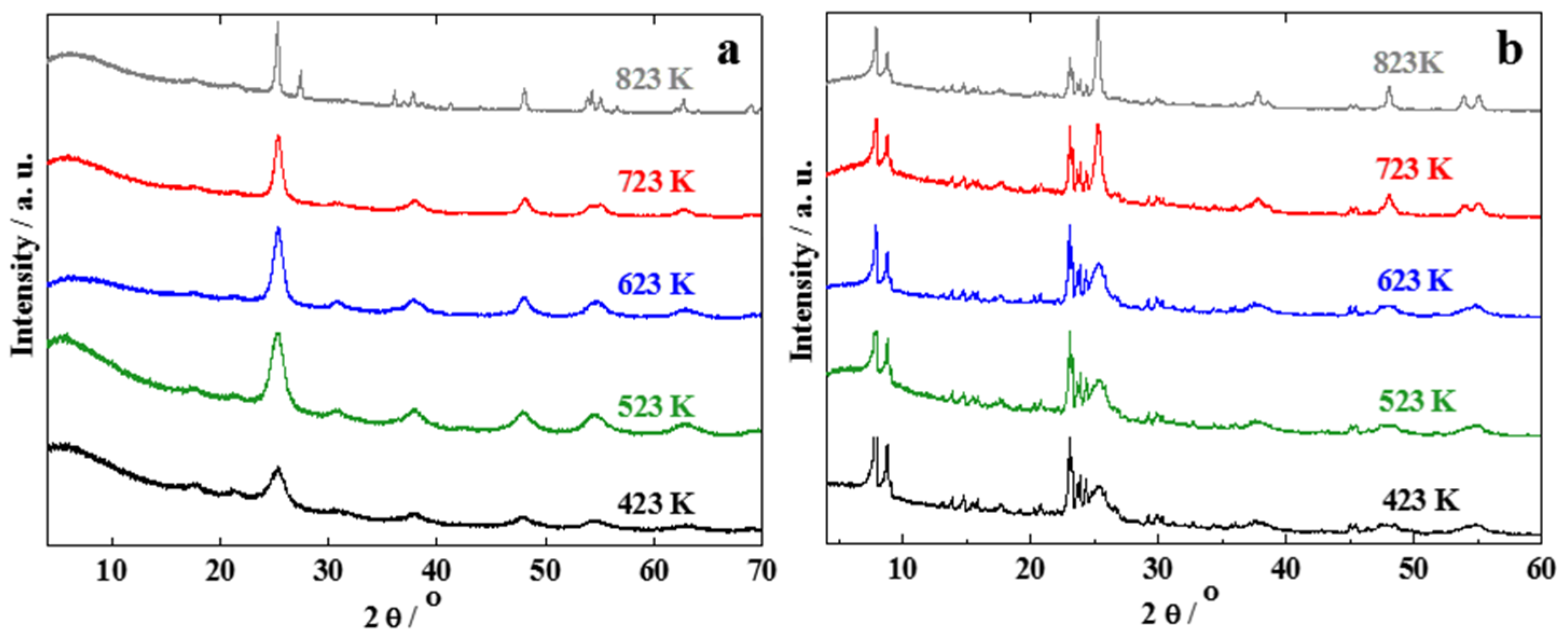
2.3. Effect of Calcination Temperature

In an attempt to increase the photocatalytic activity of the composites according to [19], the calcination temperature of TiO2 and the most active and selective TiO2/ZSM-5 composite with equal mass fractions of the two components (TZSG (50/50)) from sol-gel synthesis was varied in the range of 423 to 823 K. With increasing calcination temperature, the reflexes in the XRD patterns of the TiO2 component become sharper and more intense, indicating the presence of larger crystallites (Figure 6). For the highest calcination temperature of 823 K, the reflex at 2θ = 27.5° points at the presence of the rutile phase of TiO2. The average crystallite sizes of the anatase phase determined by the Scherrer equation from the (101) reflex at 2θ = 25.4° increases slightly from 6 to 9 nm with the calcination temperature until 723 K, while much larger crystals of 23 nm are found after calcination at 823 K (Table 3). As expected for the increasing crystal size with increasing calcination temperature, the specific surface area of the composite also decreases gradually from 290 to 193 m2·g−1, respectively, in accordance with the increasing pore width (Table 3). This increase of the crystallite size with calcination temperature is in agreement with the literature [19] and can be attributed to the thermally promoted crystallite growth [48]. The formation of larger crystals at higher calcination temperatures is also observed for the TZSG-composite (Table 3). This may lead to a less intense interaction between TiO2 particles and the crystal surface of zeolite ZSM-5.
The highest photocatalytic activity with respect to NO conversion is achieved for the composite calcined at 523 K (Table 4). At the lower calcination temperature of 423 K, the NO conversion is lower and more NO2 is formed similar to the pure TiO2 catalysts (cf. Table 1). It cannot be ruled out, however, that this is due to incomplete crystallization of the TiO2 at this low calcination temperature. When the composite is calcined at 623 K or higher, the photocatalytic activity decreases with the calcination temperature as evident from the lower NO conversion and the lower amount of NO removed, however at lower selectivity for NO2 than for the material calcined at 423 K.
This can be well explained by a lower surface area of the larger TiO2 crystals and is also consistent with a less intense interaction of the larger TiO2 particles with the outer surface of the zeolite crystals. For the material calcined at 823 K, the presence of rutile is expected to further deteriorate the photocatalytic activity [41,42,43]. Therefore, the calcination temperature used in this study was 523 K.

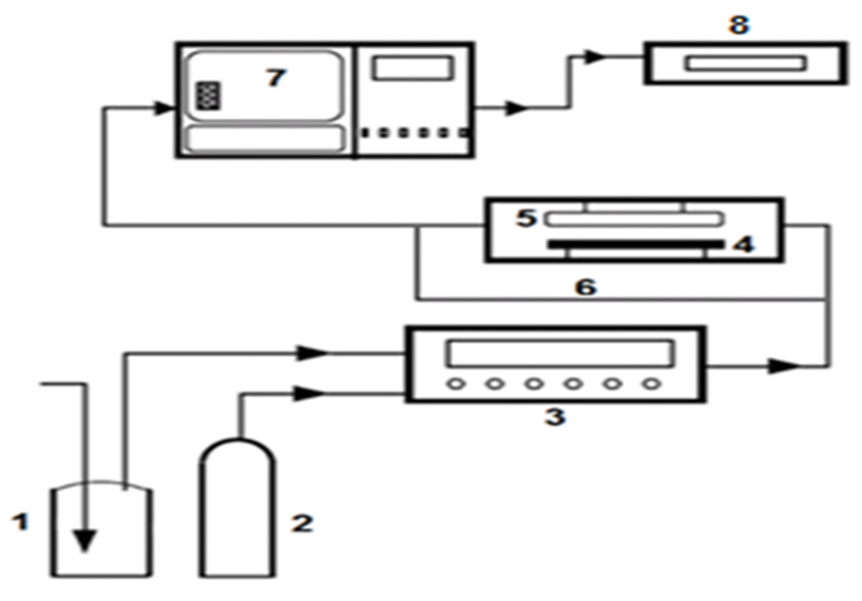
3. Experimental Section

3.1. Chemicals

Ethanol (≥99.5%) and titanium (IV) isopropoxide (TIP) (97%) were purchased from Sigma-Aldrich (St. Louis, MO, USA). The ammonium form of zeolite ZSM-5 (NH4-ZSM-5; nSi/nAl = 55) was supplied by Süd Chemie AG (Munich, Germany). TiO2 was obtained as Hombikat from Sachtleben Chemie (NRW, Duisburg, Germany) and as P25 from Evonik Degussa (Frankfurt, Germany). All chemicals were used as received without further purification.

3.2. Preparation of the TiO2/ZSM-5 Composites

3.2.1. Solid-State Dispersion

First, 1.25, 2.50 or 3.75 g of zeolite ZSM-5 was suspended in 20 cm3 of deionized water with continuous stirring for 2 h. Subsequently, 3.75, 2.50 or 1.25 g of Hombikat was added to the ZSM-5 slurry with vigorous stirring for another 2 h. Then, the slurry was dried for 12 h in an air oven at 363 K, grounded and calcined at 523 K in air for 6 h. The composites prepared by this method are referred to as HZSSD. The label HZSSD represents the Hombikat/ZSM-5 composites prepared using solid-state dispersion. The mass fractions of Hombikat to ZSM-5 are 25/75, 50/50 and 75/25, respectively.

3.2.2. Sol-Gel Synthesis

A TiO2 sol was prepared by acid-catalyzed hydrolysis of TIP according to [49]. 4.6, 9.2 or 14.4 cm3 of TIP equivalent to 1.25, 2.50 or 3.75 g of TiO2 were dissolved in 25 cm3 of ethanol (≥99.5%, Sigma-Aldrich, St. Louis, MO, USA) and vigorously stirred at room temperature for 2 h. Subsequently, 1 cm3 of 1M HNO3 (65%, VWR International, Radnor, PA, USA) was added to the solution under continuous stirring for 5 min until gelation takes place. Then, 25 cm3 of deionized water was added to the gel. The resulting gel was stirred for another 3 h. To obtain the TiO2/ZSM-5 composites with mass fractions of 25/75, 50/50 or 75/25, the TiO2 sol was added to a suspension of 3.75, 2.50 or 1.25 g of ZSM-5 in 50 cm3 of deionized water over 1h at room temperature under stirring. The resulting gel was stirred for another 6 h and dried in an air oven at 353 K for 12 h. Finally, the obtained solid was ground to a powder and calcined at 523 K in air for 6 h. These composites were named TZSG indicating the composition of TiO2/ZSM-5 prepared by sol-gel synthesis. For comparison, pure TiO2 and a composite of TiO2/sea sand (Merck) (TSSSG) were also prepared using the same sol-gel route. A TiO2/ZSM-5 composite (50/50) for the purpose of studying the influence of calcination temperature was also prepared by sol-gel method. Before calcination, the dried powder was divided equally into five parts. Each of them was calcined at different temperatures from 423 to 823 K in air for 6 h.

3.2.3. Mechanical Mixture

For comparison, zeolite ZSM-5 (1.25, 2.50 or 3.75 g) and Hombikat (3.75, 2.50 or 1.25 g) were mixed in an agate pestle and mortar and ground to a fine powder followed by calcination at 523 K in air for 6 h. The obtained mixtures are denoted as HZMM indicating the preparation by mechanical mixing of Hombikat and zeolite ZSM-5. The mass fractions of Hombikat to ZSM-5 were maintained as in the solid-state dispersion and the sol-gel synthesis, i.e., 25/75, 50/50 and 75/25, respectively.

3.3. Characterization of Photocatalysts

A micromeritics (Norcross, GA, USA) model ASAP2010 physisorption analyzer was used to record N2-sorption isotherms at 77 K for the calcined materials. The samples were pre-treated at 523 K under the vacuum (3×10⁻¹¹ MPa) for 6 h. The specific surface area ABET was determined by the Brunauer-Emmett-Teller (BET) model. The specific pore volume was estimated at the point P/P0 = 0.995, and the average pore width was calculated by the BJH model from the desorption branch of the isotherm. For characterization of the micropore volume according to the t-plot method, the pressure range of P/P0 = 0.35–0.5 was considered.
Powder XRD patterns were taken at room temperature using a Siemens D5000 diffractometer (Karlsruhe, Germany) using Cu-Kα radiation (λ = 0.154 nm) in the 2θ-range of 4° and 90° with a step size of 0.02° and a counting time of 0.2 s for phase identification.
Selected samples were analyzed by scanning electron microscopy (SEM) using E-O-GmbH CamScan CS44 (Dortmund, Germany) operated at an accelerating voltage of 10 kV. Prior to analysis, the samples were grinded into a powder, mounted on SEM stubs using a carbon tape and then sputter-coated with a thin layer of gold to avoid charging during the microscopic measurement.
Diffuse reflectance UV-Vis absorption measurements were performed on a Lambda 650 instrument (LabSphere, North Sutton, NH, USA) of Perkin-Elmer. After grinding of the samples into fine powders, a thin layer was placed in a sample holder. All samples were measured within the range 200–800 nm. The reflected light was collected by a universal reflectance sphere for all wavelengths.

3.4. Photocatalytic Experiments

The photocatalytic experiments were carried out following the standard procedure based on ISO 22197-1 [37]. The experimental setup consists of a flat-bed reactor, a NO gas supply, a humidifier, a UV lamp (Ultra-Vitalux 300 W (OSRAM, München, Germany) UVA (315–400 nm) and UVB (280–315 nm)), a test gas generator model Sycos KT-GPTM (Ansyco, Karlsruhe, Germany) and a chemiluminescence NOx analyzer AC 32 M (environment S.A, Poissy, France), as shown in Figure 7.
The reactor is made from non-adsorbing polymethyl methacrylate (PMMA) with 0.48 m length, 0.10 m width, and 0.06 m height. It is covered with a quartz glass plate permitting access of UV light to the reactor. The catalyst is filled as a powder into a sample holder made of plastic (PMMA) of the following dimensions (0.1 m length, 0.05 m width and 0.01 m height) and then placed in the middle of the reactor. The UV lamp is located above the reactor at a distance between the lamp and the reactor of 76 cm to achieve the UV irradiance of 10 W·m−2 recommended by the ISO standard [37]. The amount of NO, NO2 and NOx were continuously (5 s sampling frequency) monitored at the gas outlet using the chemiluminescence NOx analyzer.
The photocatalytic NO oxidation experiments were carried out at ambient temperature and pressure. In a typical experiment, 5 g of the sample was placed in the sample holder covering an area of 0.005 m2. Then, a stream of NO (1000 ppb) in air at 50% relative humidity with a total volumetric flow rate of 3 dm3·min−1; was led through the system using a bypass. Typically, after 15 min, the desired NO and water concentrations reached a steady state at the desired values. Subsequently, the humid NO-containing feed was supplied to the reactor with the UV light turned off. After achieving adsorption equilibrium as indicated by a constant NO concentration in the gas leaving the reactor, typically after 5 min, the UV light was switched on. After 24 h on-stream, the UV light was turned off again and the outlet concentration of NO was monitored under flow of the reactant feed through the reactor until it reached the initial concentration of 1000 ppb, typically after 15 min. It was proven that no NO photolysis occurs in the absence of any catalyst, i.e., in the empty reactor with UV light irradiation for 3 h.
In order to determine the amount of NO2 and NO3 anions on the sample surface after the photocatalytic experiments, selected samples were immersed in 25 cm3 deionized water and the obtained aqueous solution was analyzed in an ion chromatograph (IC); (dionex, Sunnyvale, CA, USA). The conversion of NO ( X NO ) , Conversion of NOx ( X NO x ), the selectivity for NO2 ( S NO 2 ) , the amount of NO removed ( Z N O /µmol·m2·h1), the amount of NO2 formed ( Z NO 2 / µmol·m2·h1), and the net amount NOx removed ( Z NO x / µmol·m2·h1) were calculated according to the following equations [37,50]:
  X NO   = ( ( C NO , in C NO , out ) / C NO , in )   100 % ,
    X NO x   = ( ( C NO x , in C NO x , out ) / C NO x , in )   100 % ,
S NO 2   = ( C NO 2 , out / ( C NO , in   C NO , out ) )   100 % ,
Z NO   = ( ( f / 22.4   dm 3 · mol 1 ) 0 24 ( C NO , in C NO , out )   d t ) / A   t ,
Z NO 2   = ( ( f / 22.4   dm 3 · mol 1 ) 0 24 ( C NO 2 , out C NO 2 , in )   d t ) / A   t ,
Z NO x   = ( Z NO Z NO 2 ) ,
where C NO in and C NO 2 in are the inlet concentrations of NO and NO2, C NO out and C NO 2 out are the outlet concentration and calculated as the average outlet concentration over 24 h of irradiation time; t is the irradiation time in min ; f is the overall volumetric flow rate in dm3·min−1; A is the irradiated surface area in m 2 ; 22.4 dm3·mol−1 is the molar volume of an ideal gas at the standard state. The mass balance for NOx was closed within ±10%. The reported conversion, selectivity and Z-values are accurate within an experimental error of ±4%.

4. Conclusions

Composites of TiO2 from different sources such as Hombikat, P25, or from sol-gel synthesis, with crystalline zeolites such as ZSM-5 can be readily prepared over the complete range of mass fractions by mechanical mixing or solid-state dispersion. No apparent difference in the textural, morphological or optical properties in the composites from the two preparation techniques were observed for TiO2/ZSM‑5 composites. A significantly more homogeneous distribution of small TiO2 particles covering the outer surface of the zeolite ZSM-5 crystals was achieved by sol-gel synthesis of TiO2 in the presence of the zeolite crystals. This results in an intimate contact of both components in the composites. At higher mass fractions of the TiO2, however, increasingly large mesopores within the TiO2 phase are formed, reducing the contact area to the zeolite crystals.
The activity of the composites in the photocatalytic oxidation (PCO) of NO in a flatbed reactor under continuous flow according to ISO 22197-1 is distinctly different from that of the pure TiO2 materials. While the NO conversion is lower, the selectivity for the undesired NO2 is lower and a higher fraction of nitrate and nitrite may be formed. The role of the zeolite can, thus, be understood to be an adsorptive component for NO2, which is continuously released to the photocatalytically active TiO2 particles and further converted to the desired nitrate. Another function of the zeolite may be to adsorb the nitric acid formed by photooxidation of NOx, which otherwise deposits on the TiO2 surface and leads to deactivation by blocking of active sites. This function, would, however, be limited by the overall adsorption capacity of the zeolite which, in the experiments conducted here, was not reached.
The highest NO conversion of 41% at a NO2 selectivity as low as 19% stable for 24 h on-stream was reached over the TiO2/ZSM-5 composite with equal amounts of the two components after calcination at 523 K from sol-gel synthesis. This activity and stability for complete NO oxidation was even higher than for pure TiO2 from sol-gel synthesis, Hombikat, or P25. These favorable photocatalytic properties could be clearly attributed to the adsorptive properties of the zeolite ZSM-5 in the composite photocatalyst. They have to be balanced, however, with the photocatalytic function provided by the TiO2 and its amount in the composite.
The approach of utilizing zeolites as adsorptive components in photocatalytic composites for oxidative NOx removal may be applied to other zeolites and photoactive catalyst components. Further studies towards increasing the effectiveness of these composites should, besides long-term stability studies under the application conditions, target the balance of surface hydrophobicity/hydrophilicity with respect to adsorption capacity, i.e., specific pore volume and surface area. As the contact between the photocatalytically active and the sorptive function is of prime importance, the effect of the diameters and the shape of the zeolite crystals may also be adjusted for improving the activity and stability of composites catalysts for photooxidative NOx removal.

Supplementary Files

Supplementary File 1

Acknowledgments

The authors are grateful to Sebastian Zimmermann, Institut of Chemical Technology, Universität Leipzig, for help with the photocatalytic apparatus and to Gerald Wagner, Institute for Mineralogy, Crystallography and Material Science; Universität Leipzig, for the SEM pictures. The authors acknowledge the Ministry of Higher Education and Scientific Research-Libya for financial support.

Author Contributions

Roger Gläser provided the idea and design for the study. Akram Tawari performed the experiments. Akram Tawari, Roger Gläser and Wolf-Dietrich Einicke analyzed the data. Akram Tawari drafted the manuscript. Wolf-Dietrich Einicke and Roger Gläser revised it.

Conflicts of Interest

The authors declare no conflict of interest.

References

  1. Farrell, A. Multi-lateral emission trading: Lessons from inter-state NOx control in the United States. Energy Policy 2001, 29, 1061–1072. [Google Scholar] [CrossRef]
  2. Castro, T.; Madronich, S.; Rivale, S.; Muhlia, A.; Mar, B. The influence of aerosols on photochemical smog in Mexico City. Atmos. Environ. 2001, 35, 1765–1772. [Google Scholar] [CrossRef]
  3. Devahasdin, S.; Fan, C.; Li, K.Y.; Chen, D.H. TiO2 photocatalytic oxidation of nitric oxide: Transient behavior and reaction kinetics. J. Photochem. Photobiol. A 2003, 156, 161–170. [Google Scholar] [CrossRef]
  4. Cooper, C.D.; Alley, F.C. Air Pollution Control: A Design Approach, 4th ed.; Waveland Press: Long Grove, IL, USA, 2011; pp. 535–543. [Google Scholar]
  5. Tang, X.L.; Hao, J.M.; Xu, W.G.; Li, J.H. Low temperature selective catalytic reduction of NOx with NH3 over amorphous MnOx catalysts prepared by three methods. Catal. Commun. 2007, 8, 329–334. [Google Scholar] [CrossRef]
  6. Lim, T.H.; Jeong, S.M.; Kim, S.D.; Gyenis, J. Photocatalytic decomposition of NO by TiO2 particles. J. Photochem. Photobiol. A 2000, 134, 209–217. [Google Scholar] [CrossRef]
  7. Pleskov, Y.V.; Fujishima, A.; Hashimoto, K.; Watanabe, T. TiO2 photocatalysis: Fundamentals and applications. Russ. J. Electrochem. 1999, 35, 1137–1138. [Google Scholar]
  8. Fujishima, A.; Honda, K. Electrochemical photolysis of water at a semiconductor electrode. Nature 1972, 238, 37–38. [Google Scholar] [CrossRef] [PubMed]
  9. Ibusuki, T.; Takeuchi, K. Removal of Low concentration nitrogen-oxides through photoassisted heterogeneous catalysis. J. Mol. Catal. 1994, 88, 93–102. [Google Scholar] [CrossRef]
  10. Fujishima, A.; Rao, T.N.; Tryk, D.A. TiO2 photocatalysts and diamond electrodes. Electrochim. Acta 2000, 45, 4683–4690. [Google Scholar] [CrossRef]
  11. Fujishima, A.; Zhang, X. Titanium dioxide photocatalysis: Present situation and future approaches. C. R. Chim. 2006, 9, 750–760. [Google Scholar] [CrossRef]
  12. Wang, H.; Wu, Z.; Zhao, W.; Guan, B. Photocatalytic oxidation of nitrogen oxides using TiO2 loading on woven glass fabric. Chemosphere 2007, 66, 185–190. [Google Scholar] [CrossRef] [PubMed]
  13. Poon, C.S.; Cheung, E. NO removal efficiency of photocatalytic paving blocks prepared with recycled materials. Constr. Build. Mater. 2007, 21, 1746–1753. [Google Scholar] [CrossRef]
  14. Maggos, T.; Bartzis, J.G.; Liakou, M.; Gobin, C. Photocatalytic degradation of NOx gases using TiO2-containing paint: A real scale study. J. Hazard. Mater. 2007, 146, 668–673. [Google Scholar] [CrossRef] [PubMed]
  15. Hüsken, G.; Hunger, M.; Brouwers, H.J.H. Experimental study of photocatalytic concrete products for air purification. Build. Environ. 2009, 44, 2436–2474. [Google Scholar] [CrossRef]
  16. Hassan, M.M.; Dylla, H.; Mohammad, L.N.; Rupnow, T. Evaluation of the durability of titanium dioxide photocatalyst coating for concrete pavement. Constr. Build. Mater. 2010, 24, 1456–1461. [Google Scholar] [CrossRef]
  17. Martinez, T.; Bertron, A.; Ringot, E.; Escadeillas, G. Degradation of NO using photocatalytic coatings to different substrates. Build. Environ. 2011, 46, 1808–1816. [Google Scholar] [CrossRef]
  18. Guo, S.; Wu, Z.; Zhao, W. TiO2-based building materials above and beyond traditional applications. Chin. Sci. Bull. 2009, 54, 1137–1142. [Google Scholar] [CrossRef]
  19. Hashimoto, K.; Wasada, K.; Toukai, N.; Kominami, H.; Kera, Y. Photocatalytic oxidation of nitrogen monoxide over titanium (IV) oxide nanocrystals large size areas. J. Photochem. Photobiol. A 2000, 136, 103–109. [Google Scholar] [CrossRef]
  20. Nakamura, I.; Sugihara, S.; Takeuchi, K. Mechanism for NO photooxidation over the oxygen-deficient TiO2 powder under visible light irradiation. Chem. Lett. 2000, 11, 1276–1277. [Google Scholar] [CrossRef]
  21. Dalton, J.S.; Janes, P.A.; Jones, N.G.; Nicholson, J.A.; Hallam, K.R.; Allen, G.C. Photocatalytic oxidation of NOx gases using TiO2: A surface spectroscopic approach. Environ. Pollut. 2002, 120, 415–422. [Google Scholar] [CrossRef]
  22. Ichiura, H.; Kitaoka, T.; Tanaka, H. Photocatalytic oxidation of NOx using composite sheets containing TiO2 and a metal compound. Chemosphere 2003, 51, 855–860. [Google Scholar] [CrossRef]
  23. Takeda, N.; Torimoto, T.; Sampath, S.; Kuwabata, S.; Yoneyama, H. Effect of inert supports for titanium-dioxide loading on enhancement of photodecomposition rate of gaseous propionaldehyde. J. Phys. Chem. 1995, 99, 9986–9991. [Google Scholar] [CrossRef]
  24. Anderson, C.; Bard, A.J. Improved photocatalytic activity and characterization of mixed TiO2/SiO2 and TiO2/Al2O3 materials. J. Phys. Chem. B 1997, 101, 2611–2616. [Google Scholar] [CrossRef]
  25. Matos, J.; Laine, J.; Herrmann, J.M. Synergy effect in the photocatalytic degradation of phenol on a suspended mixture of titania and activated carbon. Appl. Catal. B 1998, 18, 281–291. [Google Scholar] [CrossRef]
  26. Fichtner, S.; Hofmann, J.; Möller, A.; Schrage, C.; Giebelhausen, J.M.; Böhringer, B.; Gläser, R. Decomposition of 2-chloroethylethylsulfide on copper oxides to detoxify polymer-based spherical activated carbons from chemical warfare agents. J. Hazard. Mater. 2013, 262, 789–795. [Google Scholar] [CrossRef] [PubMed]
  27. Portela, R.; Tessinari, R.F.; Suarez, S.; Rasmussen, S.B.; Alonso, M.D.H.; Canela, M.C.; Avila, P.; Sanchez, B. Photocatalysis for continuous air purification in wastewater treatment plants: From lab to reality. Environ. Sci. Technol. 2012, 46, 5040–5048. [Google Scholar] [CrossRef] [PubMed]
  28. Mahalakshmi, M.; Priya, S.V.; Arabindoo, B.; Palanicharnly, M.; Murugesan, V. Photocatalytic degradation of aqueous propoxur solution using TiO2 and H beta zeolite-supported TiO2. J. Hazard. Mater. 2009, 161, 336–343. [Google Scholar] [CrossRef] [PubMed]
  29. Corma, A. From microporous to mesoporous molecular sieve materials and their use in catalysis. Chem. Rev. 1997, 97, 2373–2419. [Google Scholar] [CrossRef] [PubMed]
  30. Zhang, J.L.; Minagawa, M.; Matsuoka, M.; Yamashita, H.; Anpo, M. Photocatalytic decomposition of NO on Ti-HMS mesoporous zeolite catalysts. Catal. Lett. 2000, 66, 241–243. [Google Scholar] [CrossRef]
  31. Guo, G.F.; Hu, Y.; Jiang, S.M.; Wei, C.H. Photocatalytic oxidation of NOx over TiO2/HZSM-5 catalysts in the presence of water vapor: Effect of hydrophobicity of zeolites. J. Hazard. Mater. 2012, 223, 39–45. [Google Scholar] [CrossRef] [PubMed]
  32. Hashimoto, K.; Wasada, K.; Osaki, M.; Shono, E.; Adachi, K.; Toukai, N.; Kominami, H.; Kera, Y. Photocatalytic oxidation of nitrogen oxide over titania-zeolite composite catalyst to remove nitrogen oxides in the atmosphere. Appl. Catal. B 2001, 30, 429–436. [Google Scholar] [CrossRef]
  33. Ichiura, H.; Kitaoka, T.; Tanaka, H. Preparation of composite TiO2-zeolite sheets using a papermaking technique and their application to environmental improvement—Part I—Removal of acetaldehyde with and without UV irradiation. J. Mater. Sci. 2002, 37, 2937–2941. [Google Scholar] [CrossRef]
  34. Ichiura, H.; Kitaoka, T.; Tanaka, H. Removal of indoor pollutants under UV irradiation by a composite TiO2-zeolite sheet prepared using a papermaking technique. Chemosphere 2003, 50, 79–83. [Google Scholar] [CrossRef]
  35. Takeuchi, M.; Kimura, T.; Hidaka, M.; Rakhmawaty, D.; Anpo, M. Photocatalytic oxidation of acetaldehyde with oxygen on TiO2/ZSM-5 photocatalysts: Effect of hydrophobicity of zeolites. J. Catal. 2007, 246, 235–240. [Google Scholar] [CrossRef]
  36. Jansson, I.; Suárez, S.; Javier Garcia-Garcia, F.; Sánchez, B. Zeolite-TiO2 hybrid composites for pollutant degradation in gas phase. Appl. Catal. B 2015, 178, 100–107. [Google Scholar] [CrossRef]
  37. ISO. Fine Ceramics (Advanced Ceramics, Advanced Technical Ceramics)—Test Method for Air-Purification Performance of Semi Conducting Photocatalytic Materials—Part 1: Removal of Nitric oxide, 1st ed.; ISO: Geneva, Switzerland, 2007. [Google Scholar]
  38. Hu, Y.; Tsai, H.L.; Huang, C.L. Phase transformation of precipitated TiO2 nanoparticles. Mater. Sci. Eng. A 2003, 344, 209–214. [Google Scholar] [CrossRef]
  39. Wongkalasin, P.; Chavadej, S.; Sreethawong, T. Photocatalytic degradation of mixed azo dyes in aqueous wastewater using mesoporous-assembled TiO2 nanocrystal synthesized by a modified sol-gel process. Colloids Surf. A 2011, 384, 519–528. [Google Scholar] [CrossRef]
  40. Paola, A.D.; Bellardita, M.; Palmisano, L. Brookite, the least known TiO2 photocatalyst. Catalysts 2013, 3, 36–73. [Google Scholar] [CrossRef]
  41. Zhang, J.; Zhou, P.; Liu, J.; Yu, J. New understanding of the difference of photocatalytic activity among anatase, rutile and brookite TiO2. Phys. Chem. Chem. Phys. 2014, 16, 20382–20386. [Google Scholar] [CrossRef] [PubMed]
  42. Rodella, C.B.; Nascente, P.A.P.; Franco, R.W.A.; Magon, C.J.; Mastelaro, V.R.; Florentino, A.O. Surface characterization of V2O5/TiO2 catalytic system. Phys. Status Solidi. A 2001, 187, 161–169. [Google Scholar] [CrossRef]
  43. Tanaka, K.; Capule, M.F.V.; Hisanaga, T. Effect of crystallinity of TiO2 on its photocatalytic action. Chem. Phys. Lett. 1991, 187, 73–76. [Google Scholar] [CrossRef]
  44. Sang, S.Y.; Chang, F.X.; Liu, Z.M.; He, C.Q.; He, Y.L.; Xu, L. Difference of ZSM-5 zeolites synthesized with various templates. Catal. Today 2004, 93, 729–734. [Google Scholar] [CrossRef]
  45. Xu, Y.M.; Langford, C.H. Photoactivity of titanium dioxide supported on MCM41, zeolite X, and zeolite Y. J. Phys. Chem. B 1997, 101, 3115–3121. [Google Scholar] [CrossRef]
  46. Sing, K.S.W.; Everett, D.H.; Haul, R.A.W.; Moscou, L.; Pierotti, R.A.; Rouquerol, J.; Siemieniewska, T. Reporting physisorption data for gas solid systems with special reference to the determination of surface-area and porosity. Pure Appl. Chem. 1985, 57, 603–619. [Google Scholar] [CrossRef]
  47. Kamegawa, T.; Ishiguro, Y.; Kido, R.; Yamashita, H. Design of composite photocatalyst of TiO2 and Y-zeolite for degradation of 2-propanol in the gas phase under UV and visible light irradiation. Molecules 2014, 19, 16477–16488. [Google Scholar] [CrossRef] [PubMed]
  48. Mahshid, S.; Askari, M.; Ghamsari, M.S. Synthesis of TiO2 nanoparticles by hydrolysis and peptization of titanium isopropoxide solution. Mater. J. Process. Technol. 2007, 189, 296–300. [Google Scholar] [CrossRef]
  49. Xu, Y.M.; Langford, C.H. Enhanced photoactivity of a titanium (IV) oxide supported on ZSM5 and zeolite A at low coverage. J. Phys. Chem. 1995, 99, 11501–11507. [Google Scholar] [CrossRef]
  50. Ma, J.; Wu, H.; Liu, Y.; He, H. Photocatalytic removal of NOx over visible light responsive oxygen-deficient TiO2. J. Phys. Chem. C 2014, 118, 7434–7441. [Google Scholar] [CrossRef]
Figure 1. XRD patterns of (a) Hombikat, TiO2 from sol-gel synthesis and P25; (b) zeolite ZSM-5; (c) composites from sol-gel synthesis (TZSG); and (d) composites from mechanical mixture (HZMM).
Catalysts 06 00031 g001
Figure 2. N2 sorption isotherms of (a) Hombikat, composites from mechanical mixture (HZMM) and zeolite ZSM-5; (b) Hombikat, composites from solid-state dispersion (HZSSD) and zeolite ZSM-5; (c) composites from sol-gel synthesis (TZSG) and TiO2; (d) calculated isotherms for the TiO2 fraction of the TZSG composites. For clarity, all isotherms in parts a to c were vertically displaced by 60 cm3·g−1 except for the isotherms in part d, which were displaced by 80 cm3·g−1.
Catalysts 06 00031 g002
Figure 3. SEM images of (a) TiO2 from sol-gel synthesis; (b) Hombikat; (c) zeolite ZSM-5; (d) composite HZMM (50/50); (e) composite HZSSD (50/50); and (f) composite TZSG (50/50).
Catalysts 06 00031 g003
Figure 4. Diffuse reflectance UV-Vis absorption spectra of TiO2 from sol-gel synthesis, Hombikat, and the composites TZSG (50/50), HZSSD (50/50) and HZMM (50/50).
Catalysts 06 00031 g004
Figure 5. Concentrations of NO, NO2, NOx and UV light irradiance in the photocatalytic oxidation of NO over (a) Hombikat; (b) P25; (c) TiO2 from sol-gel synthesis; (d) composite HZSSD (50/50); (e) composite HZMM (50/50); (f) composite TZSG (50/50) (5 g TiO2 or composite, 1000 ppb NO, 50% relative humidity, 3 dm3·min−1 total volumetric flow rate, 10 W·m−2 UV irradiance, 0.005 m2 irradiated area).
Catalysts 06 00031 g005
Figure 6. XRD patterns of (a) TiO2 and (b) composite TZSG (50/50) from sol-gel synthesis after calcination at different temperatures.
Catalysts 06 00031 g006
Figure 7. Schematic flow diagram of photocatalytic setup. (1) Humidifier; (2) NO gas supply; (3) test gas generator; (4) reactor; (5) UV lamp; (6) By pass; (7) NOx analyzer; (8) Data recorder.
Catalysts 06 00031 g007
Table 1. Conversion of NO ( X NO ) and of NOx ( X NO x ), selectivity for NO2 ( S NO 2 ), amount of NO removed ( Z NO ) , amount of NO2 formed ( Z NO 2 ) , and net amount NOx removed ( Z NO x ) in the photocatalytic oxidation of NO over different TiO2 and TiO2/ZSM-5 composite catalysts after 24 h UV irradiation (5 g TiO2 or composite, 1000 ppb NO, 50% relative humidity, 3 dm3·min−1 total volumetric flow rate, 10 W·m−2 UV irradiance, 0.005 m2 irradiated area).
Catalysts X N O   / % X N O x / % Z N O / µmol·m−2·h−1 Z N O 2 / µmol ·m−2·h−1 Z N O x / µmol·m−2·h−1 S N O 2   / %
P25451670445524965
TiO2321960129131048
Hombikat351651827124752
TSSSG311250230519762
HZMM (25/75)16925710814933
HZMM (50/50)211432710322431
HZMM (75/25)241637313224138
HZSSD (25/75)281743516327137
HZSSD (50/50)302255316938430
HZSSD (75/25)291945016029035
TZSG (25/75)312348312336025
TZSG (50/50)413365513152419
TZSG (75/25)362757216640629
Table 2. Content of NO3 present in the catalysts after the photocatalytic experiment.
SamplesNO3/mg·g−1
Hombikat0.30
P250.26
TSSSG0.22
TZSG (50/50)0.66
Table 3. Crystallite sizes of TiO2 as well as specific surface area ABET and average pore width dBJH of the composite TZSG (50/50) from sol-gel synthesis after calcination at different temperatures.
Tcalcination/KCrystallite Size/nmABET/(m2·g1)dBJH/nm
42362904.16
52382784.49
62382654.57
72392195.80
823231937.62
Table 4. Conversion of NO ( X NO ) and of NOx ( X NO x ), selectivity for NO2 ( S NO 2 ), amount of NO removed ( Z NO ) , amount of NO2 formed ( Z NO 2 ) , and net amount NOx removed ( Z NO x ) in the photocatalytic oxidation of NO over different TiO2 and TiO2/ZSM-5 composite catalysts after 24 h UV irradiation (5 g TiO2 or composite, 1000 ppb NO, 50% relative humidity, 3 dm3·min−1 total volumetric flow rate, 10 W·m−2 UV irradiance, 0.005 m2 irradiated area).
Tcalcinaton/K X N O / % X N O x / % Z N O / µmol·m−2·h−1 Z N O 2 / µmol·m−2·h−1 Z N O x / µmol·m−2·h−1 S N O 2 / %
423301949428728048
523413365513152419
623383060811944719
723352854810940020
823272142915029225

