Perovskite-type LaFeO3: Photoelectrochemical Properties and Photocatalytic Degradation of Organic Pollutants Under Visible Light Irradiation


Institute of Chemistry, Chemical Technology 1, Carl von Ossietzky University Oldenburg, Carl-von-Ossietzky-Str. 9-11, 26129 Oldenburg, Germany
*
Author to whom correspondence should be addressed.
Catalysts 2019, 9(4), 342; https://doi.org/10.3390/catal9040342
Submission received: 15 February 2019
/
Revised: 2 April 2019
/
Accepted: 3 April 2019
/
Published: 8 April 2019
(This article belongs to the Special Issue Catalysis by Metals on Perovskite-Type Oxides)
Abstract
:Perovskite-type oxides lanthanum ferrite (LaFeO3) photocatalysts were successfully prepared by a facile and cost-effective sol-gel method using La(NO)3 and Fe(NO)3 as metal ion precursors and citric acid as a complexing agent at different calcination temperatures. The properties of the resulting LaFeO3 samples were characterized by powder X-ray diffraction (XRD), energy dispersive X-ray spectroscopy (EDXS), UV-Vis diffuse reflectance spectroscopy (DRS), X-ray photoelectron spectroscopy (XPS), Fourier transform infrared spectra (IR), transmission electron microscopy (TEM), N2 adsorption/desorption and photoelectrochemical tests. The photoactivity of the LaFeO3 samples was tested by monitoring the photocatalytic degradation of Rhodamine B (RhB) and 4-chlorophenol (4-CP) under visible light irradiation, the highest photocatalytic activity was found for LaFeO3 calcined at 700 °C, which attributed to the relatively highest surface area (10.6 m2/g). In addition, it was found from trapping experiments that the reactive species for degradation were superoxide radical ions (O2−) and holes (h+). Photocurrent measurements and electrochemical impedance spectroscopy (EIS) proved the higher photo-induced charge carrier transfer and separation efficiency of the LaFeO3 sample calcined at 700 °C compared to that that calcined at 900 °C. Band positions of LaFeO3 were estimated using the Mott-Schottky plots, which showed that H2 evolution was not likely.
1. Introduction
Semiconductor-based catalysis is a green technology, which gained considerable attention owing to its potential environmental applications, such as wastewater treatment, air purification and degradation of different organic contaminants [1,2,3]. In the past few decades, titanium dioxide (TiO2) as an n-type semiconductor has an attractive extensive interest as photocatalysts because of its easy availability, inertness, low costs, nontoxicity and chemical stability [4]. However, the large band gap energy for TiO2 (3.0–3.2 eV), requiring UV light that occupies around 5% of solar energy for excitation, limits its applications to a great extent [5]. Another difficulty is the high recombination rate of the photoexcited electron-hole pairs in TiO2 [6]. Many attempts have been developed to retard this electron-hole recombination and to increase the photocatalytic efficiency of TiO2, such as surface modification using a suitable metal ion and nonmetal dopant to increase the visible light absorbance and coupling with another semiconductor to enhance the charge separation efficiency [7,8]. Although in some cases improved photocatalytic activities were reported, very often the doping increased the number of structural defects acting as unwanted recombination centers. Therefore, the development of cost-effective, efficient and alternative photocatalysts with intrinsic narrow band gaps to increase the visible light response has become a research focus [9,10]. Mixed metal oxides and oxynitrides attracted interest since many of them are visible-light active, cheap, non-toxic and stable [11].
Iron is highly abundant in the earth crust and thus cheap. Many mixed metal oxides containing iron, i.e., ferrites, offer suitable band gap energy for visible light absorption. Furthermore, the position of their valence band edges is more positive than the oxidation potential of O2/H2O (1.23 V vs. NHE) rendering them suitable for the photooxidation of water [12]. The high activity of ferrites for degradation of pollutants has been proven in many studies [13,14,15]. Ferrites with a perovskite structure, with a general formula of ABO3 with for example, A = rare-earth metal ion and B = Fe3+ ion, exhibit a wide range of ferro-, piezo-, and pyro-electrical properties rendering them suitable as magneto-optical material, electrode materials, structural materials, sensors and refractory materials [16]. The perovskite LaFeO3 is employed as a catalyst, e.g., in solid oxide fuel cells, but also in devices using its good dielectric properties and high piezoelectricity.
However, LaFeO3 has also been used as a photocatalyst; several studies focused on the synthesis and the activity for photodegradation of several organic dyes under visible light irradiation [17,18,19]. Thirumalairajan et al. synthesized floral-like LaFeO3 by a surfactant-assisted hydrothermal technique and found that the porous floral nanostructure led to higher photoactivity compared to bulk LaFeO3 for the degradation of different dyes, such as rhodamine B (RhB) and methylene blue (MB) [20]. Su et al. prepared large surface area nanosized LaFeO3 particles by employing SBA-16 as a hard template and compared its visible light activity for RhB degradation with that of LaFeO3 prepared by the citric acid assisted sol-gel route [21]. Yang et al. prepared LaFeO3 by conventional co-precipitation and enhanced its activity by post-treatment in molten salt [22]. Tijare et al. [23] formed nano-crystalline LaFeO3 perovskite by the sol-gel route and claimed activity for photocatalytic hydrogen generation under visible light irradiation.
In the present work, we applied the same synthetic route for LaFeO3 as Tijare et al. but altered (i) the duration of the thermal treatment and (ii) used a pyrolysis step at 400 °C instead of using ultra-sonication or drying at 90 °C in an oven. Citric acid assisted sol-gel was chosen as a synthesis route because, in general, it is a suitable method for the synthesis of nanopowders with a well-developed high specific surface area obtained at low calcination temperature and short times without employing expensive sacrificial structure-directing agents or template structures. The visible light activity for degradation of RhB and 4-chlorophenol (4-CP) as model organic pollutants was investigated. As for Tijare et al., we also attempted hydrogen generation, however, failed with that and suspected it was based on the Mott-Schottky plots calculating band positions that the conduction band edge of LaFeO3 was too positive than the reduction potential of H2/H2O (0 V vs. NHE) to create electrons which were reductive enough to react with protons to hydrogen.
2. Results and Discussion
2.1. Structural and Optical Characterization of LaFeO3
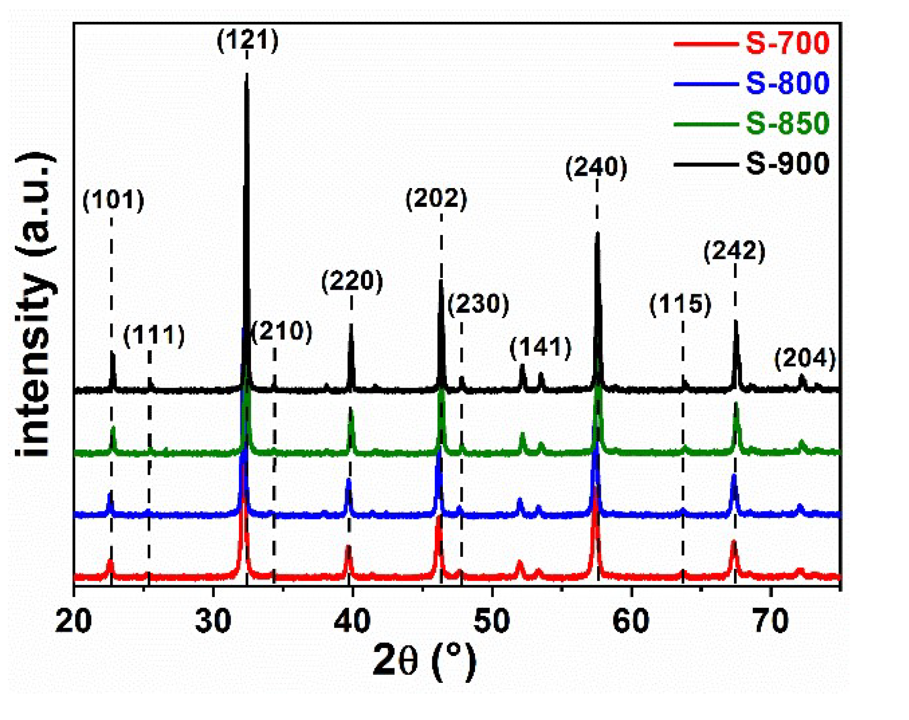
The powder XRD patterns of the prepared LaFeO3 samples after calcination at various temperatures are shown in Figure 1. All the diffraction peaks belong to the orthorhombic LaFeO3 with ABO3-type perovskite structure (JCPDS card No. 88-0641) [24]. The main characteristic reflexes are located at 2θ of 22.6°, 25.5°, 32.2°, 34.5°, 39.7°, 46.1°, 47.7°, 52.0°, 54.0°, 57.4°, 64.0°, 67.3° and 76.6°, being indexed to the (101), (111), (121), (210), (220), (202), (230), (141), (240), (115), (242) and (204) diffraction planes, respectively [24]. This confirms the effective preparation of a single phase perovskite LaFeO3 without any crystalline impurities like La2O3 or Fe2O3. For calculating the crystallite sizes the reflexes of highest intensity at 2θ = 32.2° were selected. With increasing calcination temperature the diffraction peaks get sharper and more intense, indicating a better crystallization and growth of the grains. The average crystallite sizes of LaFeO3 D have been determined by using the Debye-Scherer formula [25]:
with K being the crystallite shape factor, λ the X-ray wavelength (1.5406 nm for Cu Kα), β is the width of the diffraction peak and θ is the Bragg angle. The crystallite sizes were 27.4 nm, and 45.7 nm for S-700 and S-900, respectively. In the smaller particles, less time was needed for the electrons and holes to diffuse from the inner part to the surface of the catalyst, where they could react. This typically leads to higher photocatalytic efficiency.
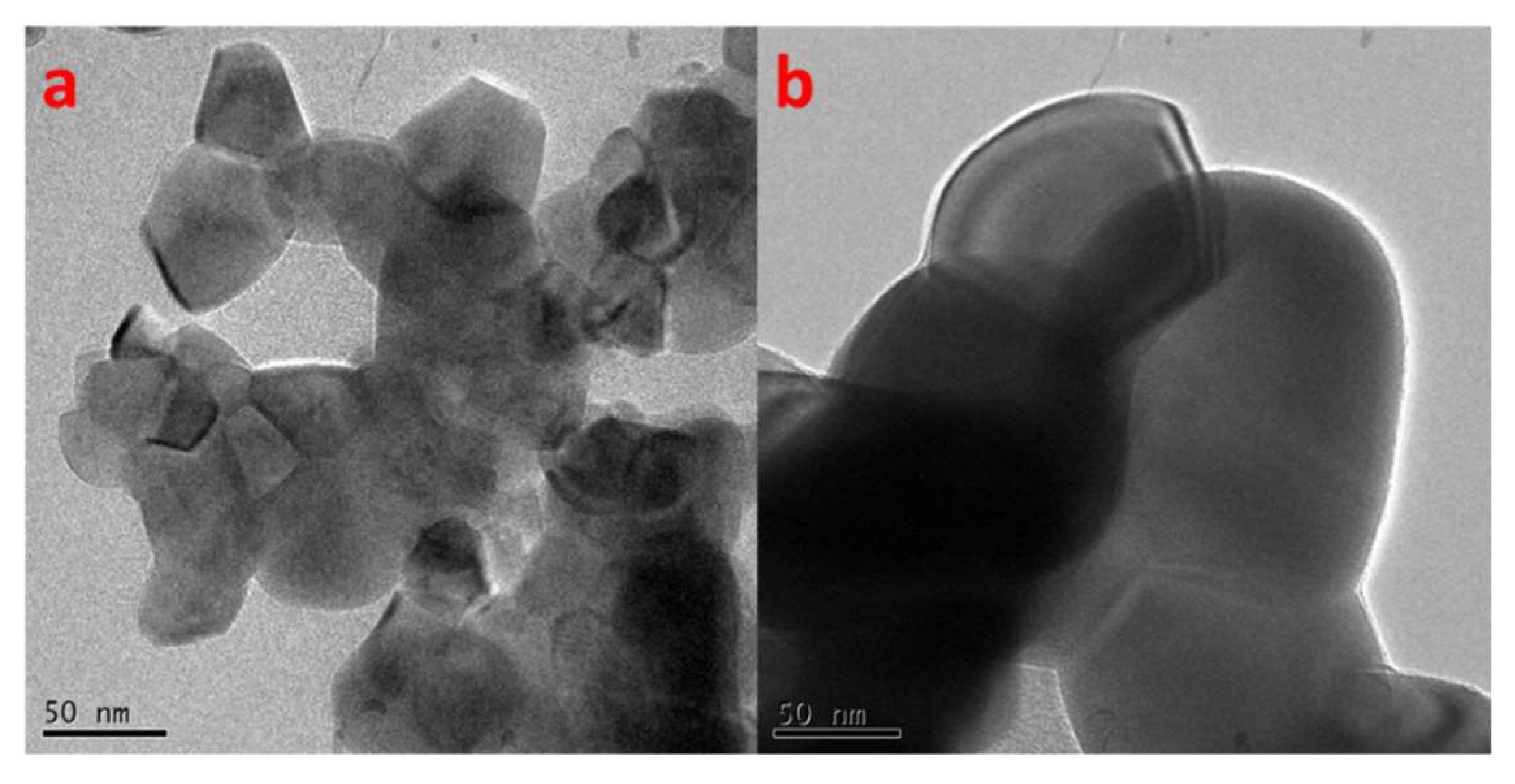
Figure 2 shows the scanning electron micrographs of the prepared LaFeO3 samples at different calcination temperatures. Scanning electron microscopy (SEM) was used to determine the morphology of the perovskite LaFeO3 samples; as seen in Figure 2 both samples show a network structure with semi-spherical morphology. It was found that the particle sizes of S-700 were significantly smaller than those of S-900, consistent with the trend of the crystallite sizes determined from XRD.
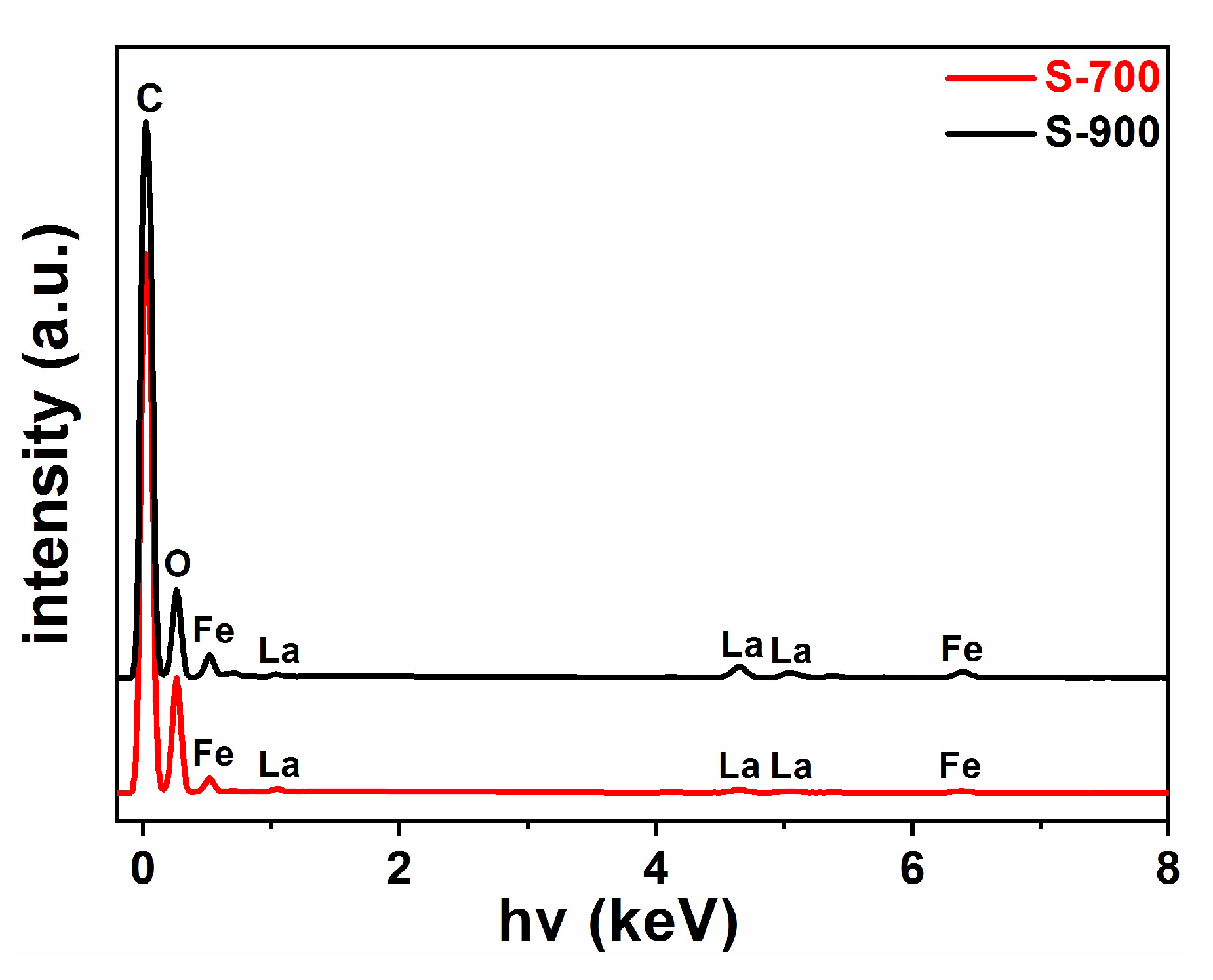
Energy dispersive X-ray spectroscopy (EDXS) was used to investigate the purity and chemical composition of synthesized LaFeO3 nanoparticles, the pattern of calcined LaFeO3 samples are shown in Figure 3. Besides a carbon signal appearing at 0.277 keV and resulting from the latex of the SEM sample holder due to the incomplete coverage of the sample [25], only lanthanum (La), iron (Fe) and oxygen (O) were present, confirming that the citric acid assisted sol-gel route leads to high purity LaFeO3 photocatalyst. The peaks at around 0.83 and 4.65 keV were related to La and the ones at around 6.399 and 0.704 keV to Fe; they proved that the formation of the LaFeO3 photocatalyst had a 1:1 molar ratio of metal ions as the atomic percentage obtained from EDXS was 0.35% for Fe and 0.34% for La in sample S-700 and 1.13% for Fe and 1.21% for La in S-900, respectively.
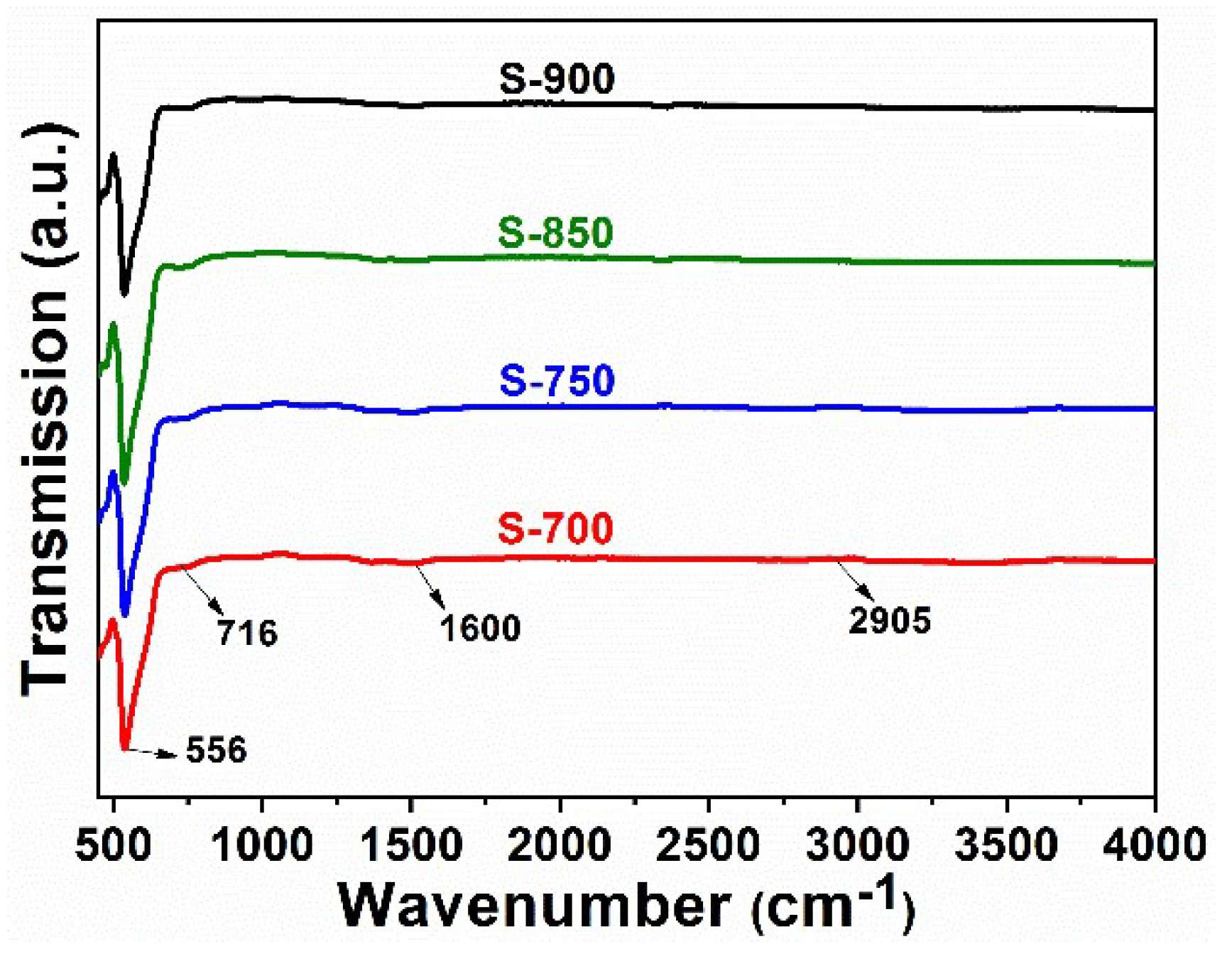
Figure 4 presents the IR spectra of different LaFeO3 samples prepared at different calcination temperatures in the wavenumber range 400–4000 cm−1 in order to determine the possible functional groups in the sample. The FT-IR spectra were quite featureless, confirming again the purity of the synthesized samples. The peak at 556 cm−1 can be attributed to the Fe–O stretching vibration being characteristic of the FeO6 octahedrons in perovskite-type LaFeO3 [26]. The band at 716 cm−1 can be assigned bending vibrations of the La-O bonds [11]; the small peak at 2905 cm−1 as well as the small peak at around 1600 cm−1 resulted from small amounts of citric acid residues, they were accounted to C-H vibrations and the symmetric stretching of the carboxyl groups, respectively.
The specific surface areas of the synthesized LaFeO3 samples were determined from a nitrogen adsorption-desorption isotherm using the BET approach. The isotherms of the samples can be classified into type III behavior (Figure 5), which is attributed to a weak adsorbate-adsorbent interaction [27]. The surface areas decreased with increasing calcination temperature. Although the surface areas were in general quite small, the area of S-700 exceeded even slightly the highest value reported by Tijare et al. of 9.5 m2/g [23]. In general, higher surface areas facilitated adsorption of organic pollutants, promoted charge carrier separation and enabled more light harvesting, resulting in total higher photocatalytic activity.
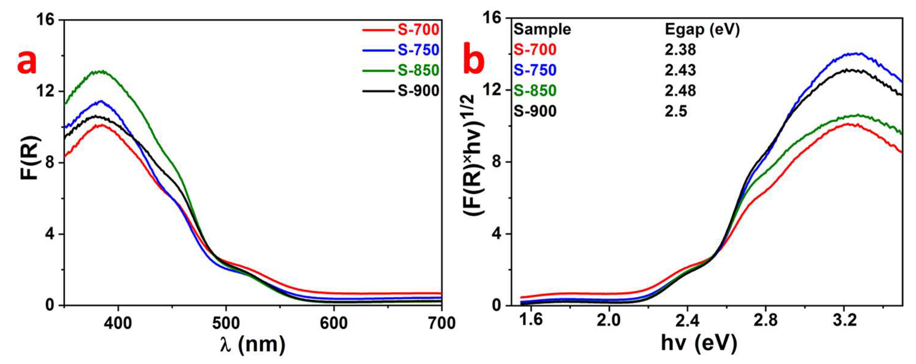
Diffuse reflectance UV-Vis spectroscopy was employed to characterize the optical properties of the LaFeO3 nanoparticles, as shown in Figure 6a. In the perovskite-type oxide, the strong absorption edge at 520 nm was ascribed to the electronic transition from the O 2p orbitals forming the valence band to the Fe 3d orbitals in the conduction band [28]. The data showed that the sol-gel prepared LaFeO3 photocatalyst could serve as a potential visible-light-driven photocatalyst. In addition, the band gap energy of LaFeO3 catalysts can be determined from Kubelka−Munk equation [29] via a Tauc plot:
with α being the absorption coefficient, ν the irradiation frequency, Eg the band gap, B being a constant (being usually 1 for semiconductors), h is the Planck constant and n is a constant depending on the type of semiconductor (direct transition: n = 1/2; indirect transition: n = 2). For the direct transition semiconductor LaFeO3, the band gap energy values were estimated by extrapolation of the linear part of the curves of the Kubelka–Munk function (αhv)1/2 against the photon energy (hv), as displayed in Figure 6b. The S-700 sample absorbed slightly more light energy than the other ones showing that a decreasing particle size and an increased surface area led to a slight red shift.
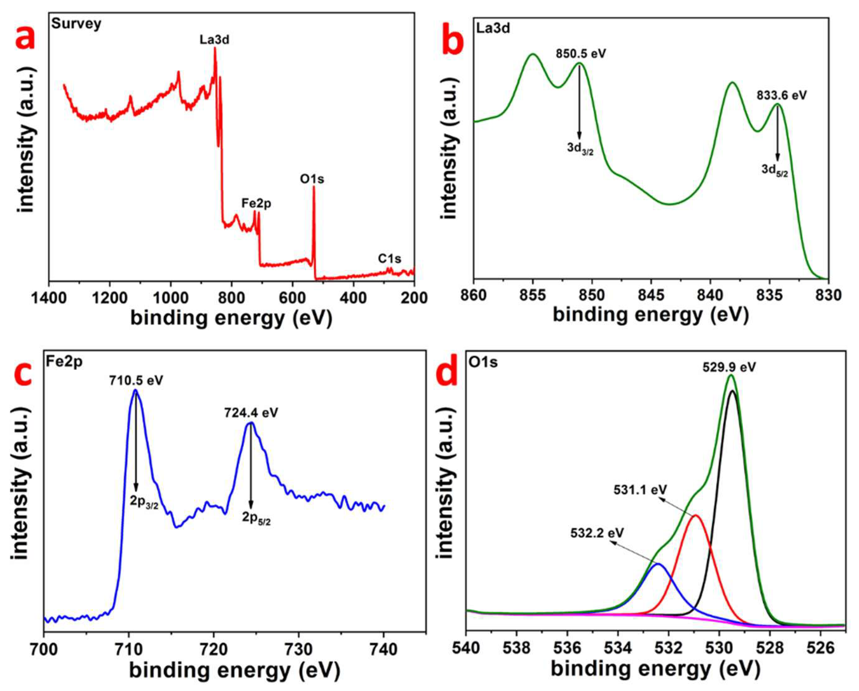
X-ray photoelectron spectroscopy (XPS) was performed on the most promising LaFeO3 S-700 to determine the elemental composition and the chemical oxidation state of the sample surface. Figure 7 shows the X-ray photoelectron (XP) survey spectrum (Figure 7a) and the detailed spectra of the La 3d, Fe 2p and O 1s. In addition to different La, Fe and O lines, Figure 7a shows also the C 1s signal, which resulted from adventitious surface carbon and which was also referenced to a binding energy (284.8 eV) in order to exclude surface charge effects for all the other signals. The binding energies found in the XP spectra of La 3d (Figure 7b) and Fe 2p (Figure 7c) revealed that the iron and lanthanum ions were both present in the chemical valence state +III [30,31]. Figure 7d shows the O 1s signal with binding energies of about 529.9 eV, 531.1 eV and 532.0 eV which corresponded as the main signal to the contribution of the La-O and Fe-O crystal lattice bonds, some surface hydroxyl groups and chemisorbed water, respectively [32,33]. In line with the expected composition between La, Fe and O, an atomic ratio of about 1:1:3 was found by comparing the relative signal intensities in the different XP spectra.
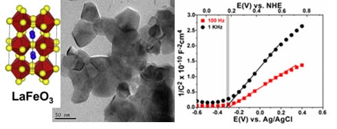
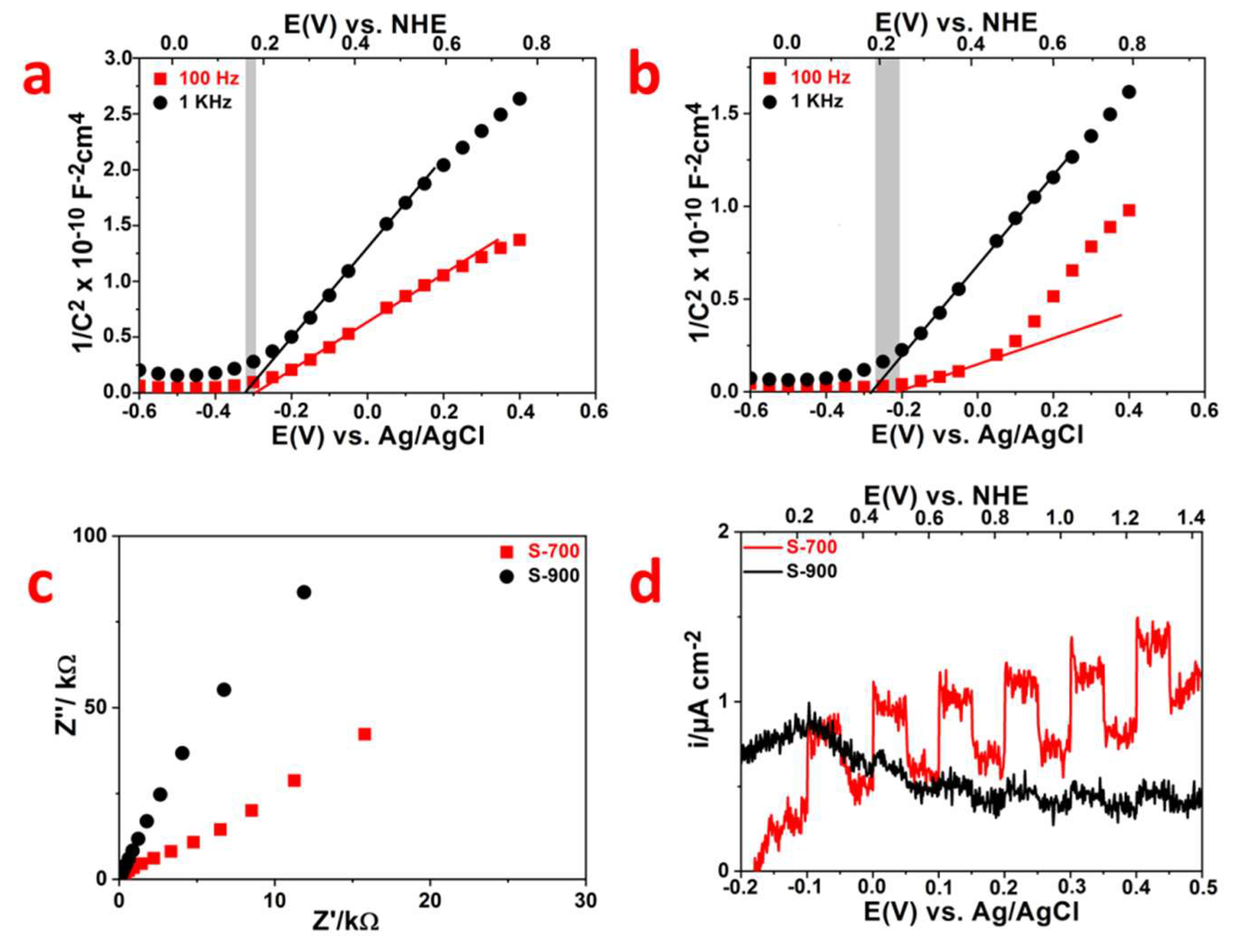
In order to investigate the energy band structure including the conduction band (CB) and valence band (VB) position of LaFeO3 S-700 and S-900 photocatalysts, electrochemical flat potential measurements were performed, and the resulting data are plotted in Figure 8a,b using the Mott–Schottky (MS) relation in the dark [34]:
with C being the capacitance of space charge, the dielectric constant, the permittivity of free space, N the electron donor density, E the applied potential and Efb the flat band potential. Plotting 1/C2 against E yields a straight line from which the slope of the donor density can be calculated and Efb can be determined as the intercept of the abscissa by extrapolation to C = 0. The positive slopes of the MS plots confirmed LaFeO3 being an n-type semiconductor with electrons as the majority charge carriers. The flat band potentials of S-700 (Figure 8a) and S-900 (Figure 8b) at frequencies of 100 Hz and 1000 Hz were calculated to be −0.3 and −0.25 V (EAg/AgCl(sat-KCl)) referenced to the KCl-saturated Ag/AgCl electrode, respectively. Thus, using the following equation:
with E0Ag/AgCl(sat-KCl) = 0.199. For the pH value of 5.6 of the 0.1 M Na2SO4 electrolyte solution, potentials were 0.23 and 0.28 V versus the normal hydrogen electrode (NHE) result. For n-type semiconductors the Efb was strongly related to the bottom of the conduction band (CB); typically, it is assumed that CB is 0.1 V more negative than Efb [35], resulting in CB edges at about 0.13 V and 0.18 V vs. NHE, respectively. These values are close to the position of the conduction band edge for YFeO3 calculated by Ismael et al. [36]. The slightly positive CB potential explains that the LaFeO3 was not able to form hydrogen via water splitting under light irradiation. This was confirmed by respective experiments attempting photocatalytic H2 formation with our LaFeO3 samples on which platinum nanoparticles (0.5 wt. %, particle size <2 nm) were photodeposited as a co-catalyst. Even by the use of light with λ ≥ 320 nm and methanol as a sacrificial agent, no hydrogen was detected with all the Pt/LaFeO3 samples. This result stands in contrast to H2 formation reported earlier by Tijare et al. [23], Parida et al. [37] and Vaiano et al. [38], who, however, performed no analysis on conduction band positions. Thus, some doubts regarding the H2 production reported in their papers exist.
Xu et al. [39] reported hydrogen production activity over a LaFeO3/g-C3N4 composite in the presence of TEOA as a sacrificial reagent and Pt as a co-catalyst. Their results show that LaFeO3 alone had no activity due to the positive conduction band edge (0.11 V); hydrogen was only found if g-C3N4 (conduction band potential at −0.85 V vs. NHE) was added, which is in agreement of our results. Hydrogen production was observed for other ferrites, such as CuFe2O4 and NiFe2O4; for those the conduction band positions were found to be negative enough [40,41].
By taking into account the band gap energies of our LaFeO3 samples from the Tauc plots (Figure 6b), the valence band (VB) positions for S-700 and S-900 can be calculated according to the equation Evb = Ecb + Eg [42], resulting in about Evb = 2.51 V and 2.68 V respectively.
Electrochemical impedance spectroscopy (EIS) and transient photocurrent experiments were performed to investigate the electron-hole separation efficiency in the LaFeO3 photocatalysts. The electrode of S-700 shows the smaller arc size (Figure 8c). In general, a smaller arc size observed in EIS semicircular Nyquist plots documents smaller charge-transfer resistance on the electrode surface and accelerated interface transport of charge carriers, which results in an effective photo-induced charge carrier mobility and separation [43,44]. Figure 8d indicates the transient photocurrent responses of S-700 and S-900. The photocurrent of S-700 sample was much higher than that of S-900 indicating the greatly improved charge transfer and separation ability [45,46]. The onset potential of the photocurrent indicates the flat band potential of the electrode [47]. In this case, the sulfate/sulfite electrolyte solution lowered the kinetic barrier for charge transport by trapping the photogenerated holes. Moreover, the onset of the photocurrent lies at about 0.2 V vs. NHE for S-700, being in good agreement with the flat band potential obtained from the Mott-Schottky plot.
2.2. Photocatalytic Properties
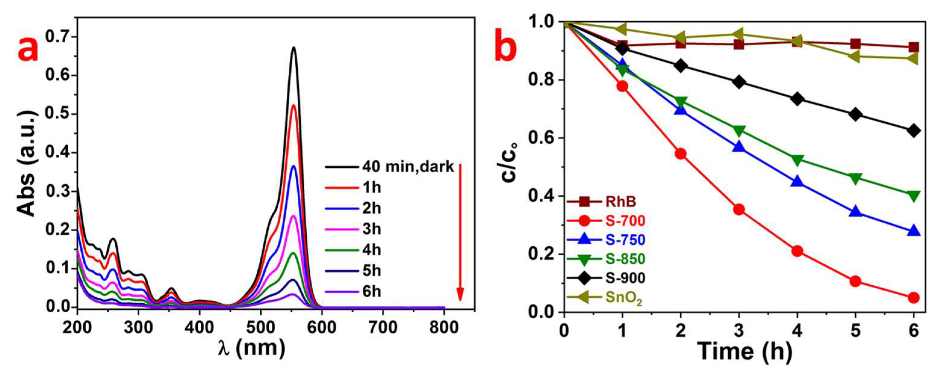
Photocatalytic activities of the prepared LaFeO3 samples were evaluated by degradation of RhB and 4-CP in aqueous solution under visible light irradiation using a 420 nm cut-off filter. Before irradiation, the suspensions were magnetically stirred in the dark for 40 min to ensure adsorption-desorption equilibrium between the organic substrate and the photocatalyst, after visible light irradiation the absorbance of RhB was noticeably reduced (Figure 9a), although there was very little decrease in absorption before irradiation. This indicates that RhB degradation occurred instead of further adsorption. Since the intensity of the absorption peaks gradually decreased without any change in their wavelength, it can be concluded that the degradation reaction takes place by an aromatic ring opening without formation of stable de-ethylated intermediates [48,49].
Figure 9b shows that without LaFeO3 being present the dye RhB was quite stable and no significant self-degradation under visible light took place. Also in the presence of SnO2, a semiconductor with a band gap of 3.0 eV, which can, thus, not be excited by light with λ ≥ 420 nm, only negligible degradation was found. Thus, sensitization effects can be ruled out as well. In the presence of the photocatalyst LaFeO3, the photodegradation efficiency decreased with increasing calcination temperature of the LaFeO3 due to the decreasing surface area and increasing particle size. Besides the highest surface area sample facilitating the adsorption of the organic dyes and possibly trapping more electrons and holes on the surface, the sample S-700 might also benefit from the slightly narrower optical band gap allowing for more visible light absorption.
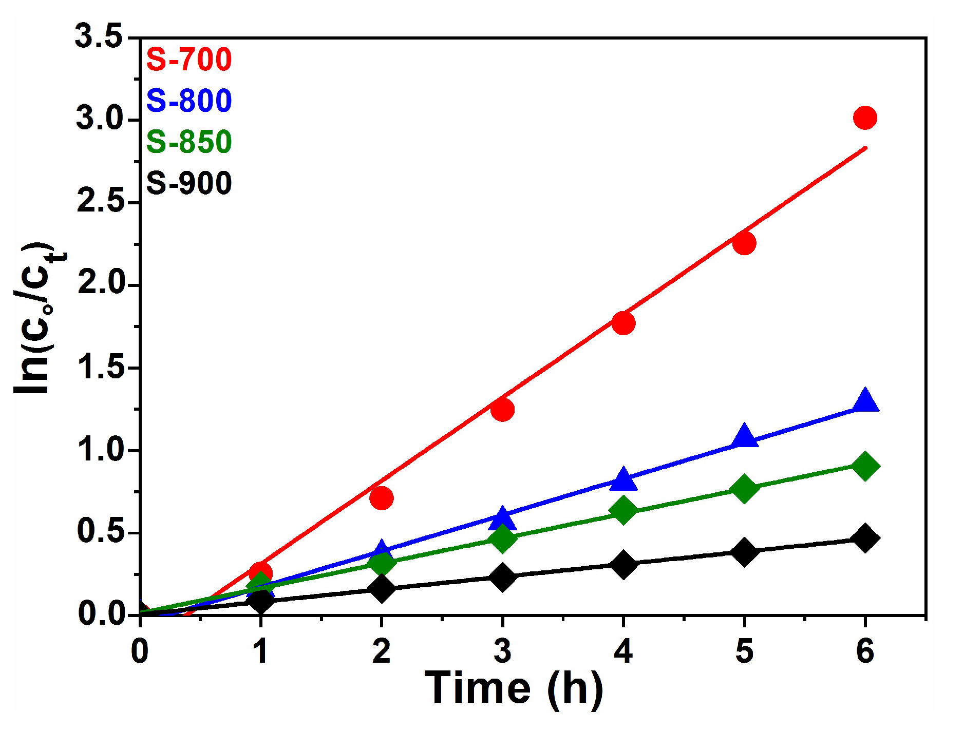
The degradation of RhB obeys a pseudo-first-order kinetics law of the type [50]:
with c0 being the initial concentration of RhB, ct the concentration of RhB at any time t, t the illumination time (min) and k is the first order rate constant (min−1). Figure 10 shows the linear relationships between ln(c0/ct) and t, the rate constant for S-700, S-750, S-850 and S-900 were 0.0062, 0.0032, 0.0026 and 0.0013 min−1, respectively.
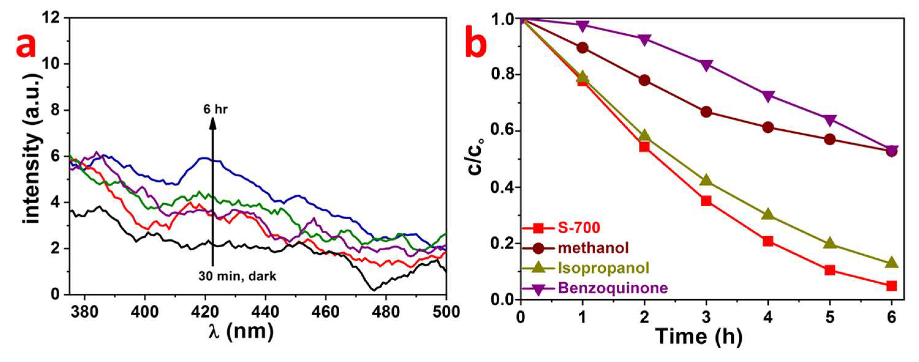
In general, it is known that the photocatalytic degradation reaction of organic contaminants proceeds mainly by the contribution of oxygen-containing reactive species such as superoxide (.O2−) and hydroxyl radicals (.OH) [51,52]. Thus, in order to explore the reactive species for RhB degradation different scavengers were tested in the photocatalytic process. The hydroxylation test was done using terephthalic acid (TA) as a probe molecule, in this test TA reacts with OH to produce highly fluorescent 2-hydroxyterepthalic acid (fluorescence maximum at 426 nm [53]).
As seen from Figure 11a for S-700 very low fluorescence intensity at 426 nm was observed after 6 h of visible light irradiation suggesting very low hydroxyl radical formation on the surface of the catalyst. Usually, the photoluminescence (PL) intensity at about 425 nm is proportional to the amount of the produced hydroxyl radical on the surface of the catalyst. In good agreement to that, isopropanol (0.01 M), a known hydroxyl radical (.OH) quencher [54], showed only little effect on the RhB degradation reaction (Figure 11b). However, the addition of benzoquinone (0.01 M) [55] as a superoxide radical (.O−2) quencher strongly decreased the degradation of RhB, indicating that degradation proceeds via superoxide radicals, which can only be produced via the reduction of dissolved oxygen by the excited electrons in the conduction band (CB) of LaFeO3. This is surprising since the CB of LaFeO3 S-700 was detected to be at about 0.1 V, being more positive than the standard potential for the superoxide radical formation from adsorbed oxygen E0(O2/•O2−) = −0.046 V [56]. Thus, the superoxide radical formation should not be possible. However, in the photocatalytic experiment, the electrochemical standard conditions were not given, thus due to potential shifts depending on the Nernst law, the superoxide radical formation might become possible to some extent. An indication for potential changes during the photocatalysis experiment might become visible in the increasing degradation of RhB in the presence of benzoquinone, which occurs with longer irradiation time (Figure 11b). Approximately the same decrease in activity for RhB degradation is obtained when 10 vol. % methanol [57] were added as a hole (h+) quencher. The photogenerated holes can oxidize OH− ions to .OH radicals because the valence band position of S-700 (2.46 V) is more positive than the redox potential of .OH/−OH (E0 = 1.99 V) [58]. These results for the active species being responsible for degradation agree with the results for the perovskite YFeO3 studied earlier by us [36]. In that paper, it was concluded that superoxide radicals (.O2) and (.OH) have an effect but the holes (h+) are the main species on catalyst surfaces responsible for the photocatalytic activities.
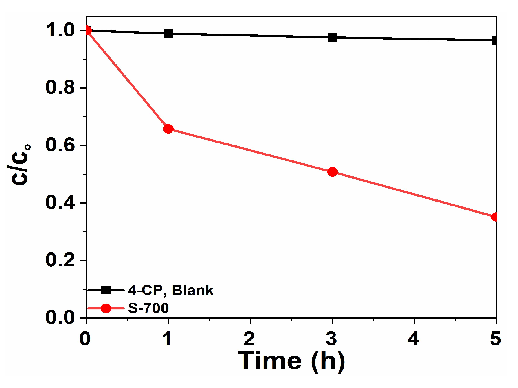
Figure 12 shows that the LaFeO3 S-700 was not only able to degrade dyes like RhB under visible-light irradiation at λ > 420 nm, but also compounds like 4-CP which does not absorb lights themselves in that spectral range. Thus, a light-induced self-degradation can be ruled out. With LaFeO3 S-700 the degradation efficiency on 4-CP was lower than that on RhB, but still more than 60% of the 4-CP were transformed by destroying the aromatic ring system, which is responsible for the absorption at 315 nm, which was recorded and followed with time in Figure 12. In a HPLC analysis performed with the reaction mixture after 5 h of illumination, no significant amounts of decomposition products were found. Total organic content (TOC) analysis after five hours illumination time confirmed the 4-CP degradation; a reduction of the TOC by 55% was found. Our LaFeO3 photocatalyst showed higher activity for 4-CP degradation compared to that reported by Pirzada et al. [59] and Hu et al. [60].
3. Experimental
3.1. Materials
All the reactants were commercial products. Iron (III) nitrate nonahydrate (Fe(NO3)3⋅9H2O, 99%), citric acid (C6H8O7, 99%) and lanthanum (III) nitrate hexahydrate (La(NO3)3⋅6H2O, 99.999%) were purchased from Sigma-Aldrich. 4-chlorophenol (4-CP, ClC6H4OH, ≥99%) and Rhodamine B (RhB, C28H31ClN2O3) were bought from Merck. All chemicals were analytically pure and were used as received without further purification. Deionized water (>18 MΩ cm) obtained from a Sartorius water purification system was used during the whole synthetic procedure to prepare the required metal ion solutions.
3.2. Synthesis of LaFeO3 by the Citric Acid Assisted Sol-gel Method
The lanthanum ferrite perovskite was synthesized by the citric acid assisted sol-gel method [23]. In a typical synthesis, Fe(NO3)3⋅9H2O (0.0041 moles), La(NO3)3⋅6H2O (0.0041 moles) and citric acid were separately dissolved in deionized water under continuous stirring in a 1:1:4 molar ratio. A high surplus of citric acid was required to chelate the metal cations and to prevent aggregation. The obtained dark yellow, clear and transparent solution was obtained after the powders were completely dissolved in the solution. From that, the viscous gel was formed by heating at 300 °C for 2–3 h under continuous magnetic stirring. Subsequently, the solvent was evaporated by combustion in a pyrolysis setup at 400 °C for 1 h. The resulting fluffy powder, which was used as a precursor for LaFeO3, was crushed to a fine powder and subsequently calcined at different temperatures for 4 h in air. After cooling, the obtained samples were characterized and tested in the photocatalytic degradation. They were named S-700, S-750, S-850 and S-900 according to the calcination temperature applied.
3.3. Characterization
The crystalline phase and size of the obtained LaFeO3 nanoparticles were checked with a Empyrean theta-theta X-ray diffraction system (PANalytical, Almelo, The Netherlands) operating with Cu Kα radiation (λ = 1.540598 nm) at 40 kV and 40 mA in the 2θ range of 20–80°. The Brunauer-Emmett-Teller (BET) surface areas were calculated from nitrogen adsorption-desorption isotherms measured on a Tri Star II (Micromeritics GmbH, Aachen, Germany). All the samples were degassed at 150 °C overnight prior to the adsorption measurements.. The diffuse reflectance spectra (DRS) and UV-Vis absorption spectra of the dye solutions were measured with a Varian Cary 4000 (Mulgrave, Australia). This spectrometer could also be equipped with an Ulbricht sphere allowing the recording of UV-Vis diffuse reflectance spectra (DRS) in the region 200–800 nm using the white standard MgO as a reference. The photoluminescence (PL) spectra were recorded using a Varian Cary Eclipse fluorescence spectrophotometer (Mulgrave, Australia) at room temperature, with excitation by incident light of 380 nm. The Fourier transform infrared spectra (FT-IR) were recorded using a Bruker FT-IR Tensor 27 Spectrometer with a platinum ATR unit. The morphology of the prepared samples and the content of the elements were studied using scanning electron microscopy (Hitachi, S-3200N, Krefeld, Germany) and energy-dispersive X-ray spectroscopy (EDX Oxford INCAx-act, Abingdon, UK), respectively. Since the photocatalytic properties of the LaFeO3 strongly depend on the surface chemical state of the samples this was analyzed by X-ray photoelectron spectroscopy (XPS) with an ESCALAB 250 Xi (Thermo Fisher, East Grinstead, UK) equipped with a monochromatic Al Kα X-ray source (hν = 1486.6 eV) as the excitation source under ultrahigh vacuum conditions. The high-resolution spectra for the C 1s, O 1s, La 3d and Fe 2p photoelectron lines were recorded with a bandpass energy of 20 eV and a step size of 0.1 eV. The spectra were analyzed using Avantage software (version 5.951). Binding energies in the high-resolution spectra were calibrated by setting the C 1s signal to 284.8 eV. Electrochemical impedance spectroscopy (EIS), photocurrent measurement and Mott Schottky plots were performed on an IM6e potentiostat (Zahner Elektrik, GmbH, Kronach, Germany) and evaluated with the Thales (version 4.12) software. A standard three-electrode cell configuration with Ag/AgCl (saturated KCl), coiled Pt-wire and LaFeO3 coated FTO were used as the reference, counter and working electrodes, respectively. The working electrodes were prepared on the conductive fluorine-doped tin oxide (FTO) glass slides (Pilkington, Weiherhammer, Germany) of 2 × 6 cm size, which were sonicated before by applying in a sequence 0.1 M HCl, 0.1 M NaOH, acetone and ethanol in an ultrasonic bath, then rinsed with deionized water and dried in an air stream. Then 0.1 g of the respective LaFeO3 sample was dispersed in 500 µl of ethanol in an ultrasonic bath for 30 min and 200 µl of the obtained suspension were coated on the FTO glass substrate using the doctor blade method. Finally, the FTO substrate was dried in a furnace for 30 min at 353 K and calcined for 3 h at 873 K. An electrolyte 0.1 M Na2SO4 aqueous solution was used for the Mott-Schottky measurements and a 0.1 M Na2SO4/0.1 M Na2SO3 aqueous solution was used as the supporting electrolyte for photocurrent and electrochemical impedance measurements, respectively.
3.4. Photocatalytic Degradation Activity and Hydrogen Evolution Measurements
The photocatalytic activity of the LaFeO3 samples was tested on one hand by the photocatalytic decomposition of RhB and 4-CP as organic model pollutants under visible light irradiation (λ ≥ 420 nm) and on the other hand by attempting hydrogen evolution using light of λ ≥ 320 nm and Pt nanoparticles as a co-catalyst.
For the degradation experiments the visible light irradiation was obtained from a 150 W Xe lamp equipped with a 420 nm cut-off filter. This optical cut-off filter was placed between the reactor and the xenon lamp to cut off the UV light and to ensure visible light irradiation only; the distance between the light source and the reactor containing solution was about 10 cm. Since for dyes, such as RhB, self-excitation by the visible light could not be ruled out (although we found there was not much indication for that, compare Figure 9b), 4-CP was used as a control substrate, which is not absorbing in the vis-light range. In a typical test, 0.1 g of LaFeO3 and 100 mL of aqueous solutions (10−5 M) of RhB or 4-CP were initially mixed under continuous magnetic stirring in a water-cooled (10 °C) double-wall 250 mL Pyrex reactor for 40 min in the dark to establish the adsorption-desorption equilibrium between the photocatalyst and substrate (RhB or 4-CP). The cooling system was used to cool down the double-wall Pyrex reactor to prevent the effect of the thermal catalytic reaction. Then the samples were illuminated under visible light. Every one hour, a part of the suspension was taken out, filtered to remove the particles and analyzed by the UV-Vis absorption measurement, the degree of degradation was evaluated from the decrease of absorption at the RhB and 4-CP maxima at 554 nm and 315 nm, respectively.
Photocatalytic H2 evolution was attempted in a double-walled quartz reaction vessel connected to a closed gas circulation, using a 500 W Hg mid-pressure immersion lamp (Peschl UV-Consulting) as a light source. Argon gas was used as the carrier gas with a flow of 50 NmL min−1. The evolved hydrogen gas was quantitatively analyzed by a multichannel analyzer (Emerson) equipped with a thermal conductivity detector. In a typical photocatalytic reaction, 0.5 g of LaFeO3 photocatalysts were suspended in a mixture of 550 mL water and 50 mL of the sacrificial agent methanol prior to the irradiation. The solution was kept at 10 °C by flushing cold water from a thermostat (LAUDA) through a double-wall reactor made of normal glass. The normal glass mantle was tested to absorb all the light with wavelengths shorter than about 320 nm. Thus, one can assume that the LaFeO3 samples are only irradiated by light of λ ≥ 320 nm. The co-catalyst 0.5 wt. % Pt (particle size < 2 nm) was deposited on the LaFeO3 powder via reductive photodeposition from H2PtCl6⋅6H2O. Upon light irradiation, metallic Pt nanoparticles were photodeposited onto the photocatalyst surface sites preferentially accessible for electrons, while CO2 was formed from methanol being employed as a sacrificial reagent as qualitatively detected with our multichannel analyzer (Emerson). The standard redox potential for the reduction of Pt2+ ions to metallic Pt is +1.2 V vs. NHE, thus the electrons in the CB of LaFeO3 are able to initiate this reduction.
4. Conclusions
A perovskite-type LaFeO3 photocatalyst was synthesized using the quite simple citric acid assisted sol-gel route. The prepared samples were characterized using different methods. The most photocatalytically active sample for decomposition of RhB and 4-CP under visible light was the one calcined at the lowest temperature of 700 °C due to the highest surface area and the lowest band gap energy. At temperatures lower than 700 °C the crystallinity of the LaFeO3 samples was not sufficient. Mott-Schottky plots revealed a positive potential of the CB at around 0.1 V explaining the observed inactivity of LaFeO3 for the photocatalytic hydrogen evolution via water splitting and methanol dehydrogenation. The photocatalytic degradation reaction of the pollutants occurred mainly via direct reaction of the photogenerated holes, but to some extent especially in the starting period of the degradation experiments also via superoxide radical formation. To sum up, LaFeO3 is a promising photocatalytic material for degradation of organic pollutants under visible light irradiation.
Author Contributions
M.I. performed the catalyst preparation, structural and electrochemical characterization and the photocatalytic test experiments. He also prepared the first draft of the manuscript. This work was carried out under the supervision of M.W., who also structured the discussion of the data and prepared the final version of the manuscript.
Acknowledgments
We thank Dereje H. Taffa (University of Oldenburg) for his assistance in recording XP spectra and fruitful discussions XPS and photoelectrochemical results. Financial support by the Phoenix Scholarship program (PX14DF0164) for MI, and by the German Science Foundation (Deutsche Forschungsgemeinschaft, DFG) under contracts WA 1116/28-1 and INST 184/154-1 for the X-ray diffractometer are gratefully acknowledged.
Conflicts of Interest
The authors declare no conflict of interest.
References
- Chen, X.; Shen, S.; Guo, L.; Mao, S.S. Semiconductor-based Photocatalytic Hydrogen Generation. Chem. Rev. 2010, 110, 6503–6570. [Google Scholar] [CrossRef] [PubMed]
- Hoffmann, R.M.; Martin, T.S.; Choi, W.; Bahnemann, W.D. Environmental Applications of Semiconductor Photocatalysis. Chem. Rev. 1995, 95, 69–96. [Google Scholar] [CrossRef]
- Hu, C.; Hu, X.; Guo, J.; Qu, J. Efficient Destruction of Pathogenic Bacteria with NiO/SrBi2O4 under Visible Light Irradiation. Environ. Sci. Technol. 2006, 40, 5508–5513. [Google Scholar] [CrossRef] [PubMed]
- Ng, H.Y.; Lightkap, V.I.; Goodwin, K.; Matsumura, M.; Kamat, V.P. To What Extent Do Graphene Scaffolds Improve the Photovoltaic and Photocatalytic Response of TiO2 Nanostructured Films? J. Phys. Chem. Lett. 2010, 1, 2222–2227. [Google Scholar] [CrossRef]
- Sakthivel, S.; Kisch, H. Daylight Photocatalysis by Carbon-Modified Titanium Dioxide. Angew. Chem. Int. Ed. 2003, 42, 4908–4911. [Google Scholar] [CrossRef] [PubMed] [Green Version]
- Tong, T.; Zhang, J.; Tian, B.; Chen, F.; He, D. Preparation of Fe3+ doped TiO2 catalysts by controlled hydrolysis of titanium alkoxide and study on their photocatalytic activity for methyl orange degradation. J. Hazard. Mater. 2008, 155, 572–579. [Google Scholar] [CrossRef]
- Xu, J.J.; Ao, H.Y.; Fu, G.D.; Yuan, W.S. Synthesis of Gd-doped TiO2 nanoparticles under mild condition and their photocatalytic activity. Colloid Surf. A 2009, 334, 107–111. [Google Scholar] [CrossRef]
- Dodd, A.; Mckinley, A.; Tsuzuki, T.; Sauners, M. Optical and photocatalytic properties of nanoparticulate (TiO2)x (ZnO)1−x powders. J. Alloys Compd. 2010, 489, L17–L21. [Google Scholar] [CrossRef]
- Dai, K.; Peng, Y.T.; Ke, N.D.; Wei, Q.B. Photocatalytic hydrogen generation using a nanocomposite of multi-walled carbon nanotubes and TiO2 nanoparticles under visible light irradiation. Nanotechnology 2009, 20, 125603. [Google Scholar] [CrossRef]
- Chai, B.; Peng, Y.T.; Zeng, P.; Mao, J. Synthesis of floriated In2S3 decorated with TiO2 nanoparticles for efficient photocatalytic hydrogen production under visible light. J. Mater. Chem. 2011, 21, 14587–14593. [Google Scholar] [CrossRef]
- Laokiat, L.; Khemthong, P.; Grisdanurak, N.; Sreearunothai, P.; Pattanasiriwisawa, W.; Klysubun, W. Photocatalytic degradation of benzene, toluene, ethylbenzene, and xylene (BTEX) using transition metal-doped titanium dioxide immobilized on fiberglass cloth. Korean J. Chem. Eng. 2012, 29, 377–383. [Google Scholar] [CrossRef]
- Taffa, H.D.; Dillert, R.; Ulpe, C.A.; Bauerfeind, L.C.K.; Bredow, T.; Bahnemann, W.D.; Wark, M. Photoelectrochemical and theoretical investigations of spinel type ferrites (MxFe3-xO4) for water splitting: A mini-review. J. Photon. Energy 2016, 7, 12009. [Google Scholar] [CrossRef]
- Su, H.M.; He, C.; Sharma, K.V.; Abou Asi, M.; Xia, D.; Li, Z.X.; Deng, Q.H.; Xiong, Y. Mesoporous zinc ferrite: Synthesis, characterization, and photocatalytic activity with H2O2/visible light. J. Hazard. Mater. 2012, 211–212, 95–103. [Google Scholar] [CrossRef]
- Cao, W.S.; Zhu, J.Y.; Cheng, F.G.; Huang, H.Y. ZnFe2O4 nanoparticles: Microwave-hydrothermal ionic liquid synthesis and photocatalytic property over phenol. J. Hazard. Mater. 2009, 171, 431–435. [Google Scholar] [CrossRef]
- Casbeer, E.; Sharma, K.V.; Li, Z.X. Synthesis and photocatalytic activity of ferrites under visible light. A review. Sep. Purif. Technol. 2012, 87, 1–14. [Google Scholar] [CrossRef]
- Nakanishi, T.; Masuda, Y.; Koumoto, K. Site-Selective Deposition of Magnetite Particulate Thin Films on Patterned Self-assembled Monolayers. Chem. Mater. 2004, 16, 3484–3488. [Google Scholar] [CrossRef]
- Juan, X.W.; Yun, H.S.; Yan, H.T.; Hua, Q.Y. Photocatalytic Degradation of Water-Soluble Azo Dyes by LaFeO3 and YFeO3. Adv. Mater. Res. 2012, 465, 37–43. [Google Scholar]
- Hou, L.; Sun, G.; Liu, K.; Li, Y.; Gao, F. Preparation, characterization and investigation of catalytic activity of Li-doped LaFeO3 nanoparticles. J. Sol-Gel Sci. Technol. 2006, 40, 9–14. [Google Scholar] [CrossRef]
- Tang, P.; Fu, M.; Chen, H.; Cao, F. Synthesis of Nanocrystalline LaFeO3 by Precipitation and its Visible-Light Photocatalytic Activity. Mater. Sci. Forum 2011, 694, 150–154. [Google Scholar] [CrossRef]
- Thirumalairajan, S.; Girija, K.; Masteralo, R.V.; Ponpandian, N. Photocatalytic degradation of organic dyes under visible light irradiation by floral-like LaFeO3 nanostructures comprised of nanosheet petals. New J. Chem. 2014, 38, 5480–5490. [Google Scholar] [CrossRef]
- Su, H.; Jing, L.; Shi, K.; Yao, C.; Fu, H. Synthesis of large surface area LaFeO3 nanoparticles by SBA-16 template method as high active visible photocatalysts. J. Nanopart. Res. 2010, 12, 967–974. [Google Scholar] [CrossRef]
- Yang, J.; Zhong, H.; Li, M.; Zhang, L.; Zhang, Y. Markedly enhancing the visible-light photocatalytic activity of LaFeO3 by post-treatment in molten salt. React. Kinet. Catal. Lett. 2009, 97, 269–274. [Google Scholar] [CrossRef]
- Tijare, N.S.; Joshi, V.M.; Padole, S.P.; Manguklar, A.P.; Rayalu, S.S.; Labhsetwar, K.N. Photocatalytic hydrogen generation through water splitting on nano-crystalline LaFeO3 perovskite. Int. J. Hydrog. Energy 2012, 37, 10451–10456. [Google Scholar] [CrossRef]
- Wu, H.; Hu, R.; Zhou, T.; Li, C.; Meng, W.; Yang, J. A novel efficient boron-doped LaFeO3 photocatalyst with large specific surface area for phenol degradation under simulated sunlight. CrystEngComm 2015, 17, 3859–3865. [Google Scholar] [CrossRef]
- Ju, L.; Chen, Z.; Fang, L.; Dong, W.; Zheng, F.; Shen, M. Sol-Gel Synthesis and Photo-Fenton-Like Catalytic Activity of EuFeO3 Nanoparticles. J. Am. Ceram. Soc. 2011, 94, 3418–3424. [Google Scholar] [CrossRef]
- Thirumalairajan, S.; Girija, K.; Ganesh, I.; Mangalaraj, D.; Viswanathan, C.; Balamurugan, A. Controlled synthesis of perovskite LaFeO3 microsphere composed of nanoparticles via self-assembly process and their associated photocatalytic activity. Chem. Eng. J. 2012, 209, 420–428. [Google Scholar] [CrossRef]
- Dong, G.; Zhang, L. Porous structure dependent photoreactivity of graphitic carbon nitride under visible light. J. Mater. Chem. 2012, 22, 1160–1166. [Google Scholar] [CrossRef]
- Li, K.; Wang, D.; Wu, F.; Xie, T.; Li, T. Surface electronic states and photovoltage gas-sensitive characters of nanocrystalline LaFeO3. Mater. Chem. Phys. 2000, 64, 269–272. [Google Scholar] [CrossRef]
- Marschall, R.; Soldat, J.; Wark, M. Enhanced photocatalytic hydrogen generation from barium tantalate composites. Photochem. Photobiol. Sci. 2013, 12, 671–677. [Google Scholar] [CrossRef] [PubMed]
- Qi, X.; Zhou, J.; Yue, Z.; Gui, Z.; Li, L. Auto-combustion synthesis of nanocrystalline LaFeO3. Mater. Chem. Phys. 2002, 78, 25–29. [Google Scholar] [CrossRef]
- Rida, K.; Benabbas, A.; Bouremmad, F.; Pena, A.M.; Sastre, E.; Martinez, A. Effect of calcination temperature on the structural characteristics and catalytic activity for propene combustion of sol-gel derived lanthanum chromite perovskite. Appl. Catal. A 2007, 327, 173–179. [Google Scholar] [CrossRef]
- Thirumalairajan, S.; Girija, K.; Hebalkar, Y.N.; Mangalaraj, D.; Viswanathan, C.; Ponpandian, N. Shape evolution of perovskite LaFeO3 nanostructures: A systematic investigation of growth mechanism, properties and morphology dependent photocatalytic activity. RSC Adv. 2013, 3, 7549–7561. [Google Scholar] [CrossRef]
- Zhang, J.; Li, M.; Feng, Z.; Chen, J.; Li, C. UV Raman spectroscopic study on TiO2. I. Phase transformation at the surface and in the bulk. J. Phys. Chem. B 2006, 110, 927–935. [Google Scholar] [CrossRef]
- Wu, W.; Liang, S.; Shen, L.; Ding, Z.; Zheng, H.; Su, W.; Wu, L. Preparation, characterization and enhanced visible light photocatalytic activities of polyaniline/Bi3NbO7 nanocomposites. J. Alloys Compd. 2012, 520, 213–219. [Google Scholar] [CrossRef]
- Yu, L.; Zhang, X.; Li, G.; Cao, Y.; Shao, Y.; Li, D. Highly efficient Bi2O2CO3/BiOCl photocatalyst based on heterojunction with enhanced dye-sensitization under visible light. Appl. Catal. B Environ. 2016, 187, 301–309. [Google Scholar] [CrossRef]
- Ismael, M.; Elhaddad, E.; Taffa, H.D.; Wark, M. Synthesis of Phase Pure Hexagonal YFeO3 Perovskite as Efficient Visible Light Active Photocatalyst. Catalysts 2017, 7, 326. [Google Scholar] [CrossRef]
- Parida, M.K.; Reddy, H.K.; Martha, S.; Das, P.D.; Biswal, N. Fabrication of nanocrystalline LaFeO3: An efficient sol-gel auto-combustion assisted visible light responsive photocatalyst for water decomposition. Int. J. Hydrog. Energy 2010, 35, 12161–12168. [Google Scholar] [CrossRef]
- Vaiano, V.; Iervolino, G.; Sannino, D. Enhanced Photocatalytic Hydrogen Production from Glucose on Rh-Doped LaFeO3. Chem. Eng. Trans. 2017, 60, 235–240. [Google Scholar]
- Xu, K.; Feng, J. Superior photocatalytic performance of LaFeO3/gC3N4 heterojunction nanocomposites under visible light irradiation. RSC Adv. 2017, 7, 45369–45376. [Google Scholar] [CrossRef]
- Yang, H.; Yan, J.; Lu, Z.; Cheng, X.; Tang, Y. Photocatalytic activity evaluation of tetragonal CuFe2O4 nanoparticles for the H2 evolution under visible light irradiation. J. Alloys Compd. 2009, 476, 715–719. [Google Scholar] [CrossRef]
- Rekhila, G.; Bessekhouad, Y.; Trari, M. Visible light hydrogen production on the novel ferrite NiFe2O4. Int. J. Hydrog. Energy 2013, 38, 6335–6343. [Google Scholar] [CrossRef]
- Chen, X.; Zhou, B.; Yang, S.; Wu, H.; Wu, Y.; Wu, Y.; Pan, J.; Xiong, X. In situ construction of a SnO2/g-C3N4 heterojunction for enhanced visible-light photocatalytic activity. RSC Adv. 2015, 5, 68953–68963. [Google Scholar] [CrossRef]
- He, M.Y.; Cai, J.; Zhang, H.L.; Wang, X.X.; Lin, J.H.; Teng, T.B.; Zhao, H.L.; Weng, Z.W.; Wan, L.H.; Fan, M. Comparing Two New Composite Photocatalysts, t-LaVO4/g-C3N4 and m-LaVO4/g-C3N4, for Their Structures and Performances. Ind. Eng. Chem. Res. 2014, 53, 5905–5915. [Google Scholar] [CrossRef]
- Yu, T.H.; Quan, X.; Chen, S.; Zhao, M.H.; Zhang, B.Y. TiO2–carbon nanotube heterojunction arrays with a controllable thickness of TiO2 layer and their first application in photocatalysis. J. Photochem. Photobiol. A Chem. 2008, 200, 301–306. [Google Scholar] [CrossRef]
- Lim, J.; Monllor-Satocaa, D.; Jang, S.J.; Lee, S.; Choi, W. Visible light photocatalysis of fullerol-complexed TiO2 enhanced by Nb doping. Appl. Catal. B Environ. 2014, 152–153, 233–240. [Google Scholar] [CrossRef]
- Bi, P.Y.; Quyang, X.S.; Cao, Y.J.; Ye, H.J. Facile synthesis of rhombic dodecahedral AgX/Ag3PO4 (X = Cl, Br, I) heterocrystals with enhanced photocatalytic properties and stabilities. Phys. Chem. Chem. Phys. 2011, 13, 10071–10075. [Google Scholar] [CrossRef]
- Hong, S.; Lee, S.; Jang, S.J.; Lee, S.J. Heterojunction BiVO4/WO3 electrodes for enhanced photoactivity of water oxidation. Energy Environ. Sci. 2011, 4, 1781–1787. [Google Scholar] [CrossRef]
- Li, X.; Ye, J. Photocatalytic Degradation of Rhodamine B over Pb3Nb4O13/Fumed SiO2 Composite under Visible Light Irradiation. J. Phys. Chem. C 2007, 111, 13109–13116. [Google Scholar] [CrossRef]
- Merka, O.; Yarovyi, V.; Bahnemann, D.W.; Wark, M. pH-Control of the Photocatalytic Degradation Mechanism of Rhodamine B over Pb3Nb4O13. J. Phys. Chem. C 2011, 115, 8014–8023. [Google Scholar] [CrossRef]
- Wang, X.; Zhang, L.; Lin, H.; Nong, Q.; Wu, Y.; Wu, T.; He, Y. Synthesis and characterization of ZrO2/g-C3N4 composite with enhanced visible-light photoactivity for rhodamine degradation. RSC Adv. 2014, 4, 40029–40035. [Google Scholar] [CrossRef]
- Ohtani, B. Photocatalysis A to Z- what we know and what we do not know in a scientific sense. J. Photochem. Photobiol. C Photochem. Rev. 2010, 11, 157–178. [Google Scholar] [CrossRef]
- Liu, W.; Wang, M.; Xu, C.; Chen, S. Chem. Facile synthesis of g-C3N4/ZnO composite with enhanced visible light photooxidation and photoreduction properties. Chem. Eng. J. 2012, 209, 386–393. [Google Scholar] [CrossRef]
- Yu, J.; Dai, G.; Cheng, B. Effect of Crystallization Methods on Morphology and Photocatalytic Activity of Anodized TiO2 Nanotube Array Films. J. Phys. Chem. C 2010, 114, 19378–19385. [Google Scholar] [CrossRef]
- He, M.Y.; Cai, J.; Li, T.T.; Wu, Y.; Lin, J.H.; Zhao, H.L.; Luo, F.M. Efficient degradation of RhB over GdVO4/g-C3N4 composites under visible-light irradiation. Chem. Eng. J. 2013, 215–216, 721–730. [Google Scholar] [CrossRef]
- Yang, X.; Cui, H.; Li, Y.; Qin, J.; Zhang, R.; Tang, H. Fabrication of Ag3PO4-Graphene Composites with Highly Efficient and Stable Visible Light Photocatalytic Performance. ACS Catal. 2013, 3, 363–369. [Google Scholar] [CrossRef]
- Wang, F.D.; Kako, T.; Ye, H.J. Efficient Photocatalytic Decomposition of Acetaldehyde over a Solid-Solution Perovskite (Ag0.75Sr0.25)(Nb0.75Ti0.25)O3 under Visible-Light Irradiation. J. Am. Chem. Soc. 2008, 130, 2724–2725. [Google Scholar] [CrossRef]
- Kormali, P.; Triantis, T.; Dimotikali, D.; Hiskia, A.; Papaconstantinou, E. On the photooxidative behavior of TiO2 and PW12O403−: OH radicals versus holes. Appl. Catal. B 2006, 68, 139–146. [Google Scholar] [CrossRef]
- Chen, Y.-L.; Zhang, D.-W. A Simple Strategy for the preparation of g-C3N4/SnO2 Nanocomposite Photocatalysts. Sci. Adv. Mater. 2014, 6, 1091–1098. [Google Scholar] [CrossRef]
- Pirzada, M.B.; Kunchala, K.R.P.; Naidu, S.B. Synthesis of LaFeO3/Ag2CO3 Nanocomposites for Photocatalytic Degradation of Rhodamine B and p-Chlorophenol under Natural Sunlight. ACS Omega 2019, 4, 2618–2629. [Google Scholar] [CrossRef]
- Hu, R.; Li, C.; Wang, X.; Sun, Y.; Jia, H.; Su, H.; Zhang, Y. Photocatalytic activities of LaFeO3 and La2FeTiO6 in p-chlorophenol degradation under visible light. Catal. Commun. 2012, 29, 35–39. [Google Scholar] [CrossRef]
Figure 1.
X-ray diffraction patterns of LaFeO3 obtained at different calcination temperatures.

Figure 2.
SEM images of LaFeO3 calcined at different temperatures: (a) S-700, (b) S-900.

Figure 3.
Energy dispersive X-ray (EDX) spectra of LaFeO3 at different calcination temperatures (S-700, S-900).
Figure 3.
Energy dispersive X-ray (EDX) spectra of LaFeO3 at different calcination temperatures (S-700, S-900).

Figure 4.
FT-IR spectra of LaFeO3 nanoparticles calcined at different temperatures.

Figure 5.
N2 adsorption-desorption isotherms for LaFeO3 samples and the resulting BET surface areas of the different samples.
Figure 5.
N2 adsorption-desorption isotherms for LaFeO3 samples and the resulting BET surface areas of the different samples.

Figure 6.
Kubelka-Munk diffuse reflectance UV-Vis spectra (a) and resulting band gaps from Tauc plots (b) of the studied LaFeO3 samples.
Figure 6.
Kubelka-Munk diffuse reflectance UV-Vis spectra (a) and resulting band gaps from Tauc plots (b) of the studied LaFeO3 samples.

Figure 7.
X-ray photoelectron spectroscopy (XPS) for the S-700 sample survey (a), and core level XPS of La 3d (b), Fe 2p (c) and O1s (d).
Figure 7.
X-ray photoelectron spectroscopy (XPS) for the S-700 sample survey (a), and core level XPS of La 3d (b), Fe 2p (c) and O1s (d).

Figure 8.
Mott-Schottky plots at 100 Hz and 1 kHz of (a) S-700 and (b) S-900, (c) Nyquist plots of S-700 and S-900 in 0.1 M Na2SO4 (pH = 5.6) at 0.4 V vs. Ag/AgCl and (d) transient photocurrent responses in 0.1 M Na2SO4/0.1 M Na2SO3 solution (pH = 5.6) under white LED illumination.
Figure 8.
Mott-Schottky plots at 100 Hz and 1 kHz of (a) S-700 and (b) S-900, (c) Nyquist plots of S-700 and S-900 in 0.1 M Na2SO4 (pH = 5.6) at 0.4 V vs. Ag/AgCl and (d) transient photocurrent responses in 0.1 M Na2SO4/0.1 M Na2SO3 solution (pH = 5.6) under white LED illumination.

Figure 9.
(a) UV-Vis spectra for the degradation of rhodamine B (RhB) under visible light irradiation (λ ≥ 420 nm) on the LaFeO3 S-700 sample ([RhB] = 10−5 M, catalyst weight = 0.1 g) at 25 °C. (b) Degradation of RhB as a function of irradiation time with visible light (λ ≥ 420 nm) in the presence of different LaFeO3 catalysts or SnO2 for comparison.

Figure 10.
Kinetics curves of LaFeO3 perovskites calcined at different temperatures.

Figure 11.
(a) Fluorescence spectra of the 2-hydroxyterepthalic acid solution in the presence of LaFeO3 S-700 and (b) the reactive species in trapping experiments during the degradation of RhB.
Figure 11.
(a) Fluorescence spectra of the 2-hydroxyterepthalic acid solution in the presence of LaFeO3 S-700 and (b) the reactive species in trapping experiments during the degradation of RhB.

Figure 12.
Degradation of 4-CP as a function of irradiation time without a photocatalyst and in the presence of the LaFeO3 catalyst S-700.
Figure 12.
Degradation of 4-CP as a function of irradiation time without a photocatalyst and in the presence of the LaFeO3 catalyst S-700.

© 2019 by the authors. Licensee MDPI, Basel, Switzerland. This article is an open access article distributed under the terms and conditions of the Creative Commons Attribution (CC BY) license (http://creativecommons.org/licenses/by/4.0/).
Share and Cite
MDPI and ACS Style
Ismael, M.; Wark, M. Perovskite-type LaFeO3: Photoelectrochemical Properties and Photocatalytic Degradation of Organic Pollutants Under Visible Light Irradiation. Catalysts 2019, 9, 342. https://doi.org/10.3390/catal9040342
AMA Style
Ismael M, Wark M. Perovskite-type LaFeO3: Photoelectrochemical Properties and Photocatalytic Degradation of Organic Pollutants Under Visible Light Irradiation. Catalysts. 2019; 9(4):342. https://doi.org/10.3390/catal9040342
Chicago/Turabian StyleIsmael, Mohammed, and Michael Wark. 2019. "Perovskite-type LaFeO3: Photoelectrochemical Properties and Photocatalytic Degradation of Organic Pollutants Under Visible Light Irradiation" Catalysts 9, no. 4: 342. https://doi.org/10.3390/catal9040342
Note that from the first issue of 2016, this journal uses article numbers instead of page numbers. See further details here.