Electrodeposition of Ni-W/CNT Composite Plating and Its Potential as Coating for PEMFC Bipolar Plate
by
 , ,
, ,
Jae-Hyeok Park
1, 
Tatsuya Wada
1,
Yuto Naruse
1,
Takeshi Hagio
1,2,*,
Yuki Kamimoto
1,2 and
Ichino Ryoichi
1,2 1
Department of Chemical Systems Engineering, Graduate School of Engineering, Nagoya University, Nagoya 464-8603, Japan
2
Institute of Materials Innovation, Institutes of Innovation for Future Society, Nagoya University, Nagoya 464-8601, Japan
*
Author to whom correspondence should be addressed.
Coatings 2020, 10(11), 1095; https://doi.org/10.3390/coatings10111095
Submission received: 21 October 2020
/
Revised: 10 November 2020
/
Accepted: 13 November 2020
/
Published: 16 November 2020
(This article belongs to the Section Corrosion, Wear and Erosion)
Abstract
:In this study, Ni-W/carbon nanotube (CNT) composite platings are electrodeposited onto steel plate as a possible coating material for the polymer electrolyte membrane fuel cell (PEMFC) bipolar plate, which requires high corrosion resistance under acidic environment and low contact resistance. The dispersibility of CNT in the plating bath is improved by surface modification of CNT through hydrothermal treatment in mixed acid solution. The change in electrodeposition behavior of Ni-W plating by CNT addition is investigated by cathodic polarization measurement. The corrosion resistance under acidic environment is evaluated using 0.5M H2SO4 solution and contact resistance of the composite platings is measured and compared with Ni and Ni-W plating. The surface modification of CNT through hydrothermal treatment is found to increase the CNT content in the Ni-W/CNT composite plating up to 0.33 mass.% and sufficient incorporation of hydrothermally treated CNT in Ni-W plating results in low contact resistance and enhanced corrosion resistance than pristine Ni-W plating.
1. Introduction
Fuel cells are attracting attention as an ideal power source owing to their ability to produce electricity from hydrogen without harmful emissions compared to those relying on traditional fossil fuels [1,2]. The reaction product of fuel cell is only water and can significantly reduce CO2 emissions, contribute to reducing the environmental load. Among them, polymer electrolyte membrane fuel cell (PEMFC) is a promising power source for fuel cell vehicles [3]. Of the various PEMFC stack parts, the bipolar plate is considered as a core part. The bipolar plate plays an important role in PEMFC as follows: separating each fuel cell, providing a conductive path by connecting the cathode and anode, supplying a reaction gas to each electrode through a flow path and removing heat and water as a reaction product. The following properties are required for PEFMC bipolar plate—low cost, mechanical properties that can bare the operating environment during its lifetime, high electrical conductivity enabling accumulation of cell voltage, high corrosion resistance under acidic environment to prevent dissolution of metal ions that cause cell voltage drop [4]. Electrical conductivity and corrosion resistance are considered to be particularly important among these properties. Especially, a highly corrosion-resistive material that does not corrode in an acidic environment is essential because the operating environment of the PEMFC corresponds to a strongly acidic environment. Metal ions eluted by corrosion of metals are absorbed to the solid polymer electrolyte membrane increases hydrogen ion conduction resistance and decreases cell voltage. It also causes degradation of the physical properties of the membrane and trigger embrittlement and cracking [5,6].
Currently, carbon and metal materials are considered as appropriate bipolar plate materials [4]. Carbon materials have excellent corrosion resistance and chemical stability but these have some drawbacks for applying to automobiles due to their weak mechanical properties and low processability. The metal materials have excellent mechanical properties, high electrical conductivity, thus considered as suitable for a bipolar plate material with a relatively low price. Generally, stainless steel [7,8,9], aluminum [10,11] and titanium [12,13] are promising but the stainless steel and aluminum has insufficient corrosion resistance and the titanium has cost problems. As a method for improving the corrosion resistance of metal materials, a surface treatment of metals such as nitriding [14,15], physical vapor deposition [16], plating [10,17,18] methods are expected as a possible solution. Among these methods, plating has advantages such as relatively low production cost, formation of uniform coating layer, suitable for mass production and applicable to complex shaped materials. For high corrosion resistance and electric conductivity, noble metal plating such as gold [13], silver [19], platinum [20] are effective but the high costs of these materials hinder their application.
In this study, electrodeposition of Ni-W plating, which exhibits a higher corrosion resistance than Ni and Ni-P plating, is considered as a possible coating material for the bipolar plate. Ni-W platings have been reported to have excellent tribological and anti-corrosion properties owing to the formation of oxide film by its tungsten component [21,22,23,24,25]. However, the formation of such oxide film at coating surface may lower the electrical conductivity. Therefore, composite platings incorporating carbon nanotube (CNT) is investigated to improve the conductivity of the Ni-W platings. Because CNT has a high electric conductivity and fibrous structure, it is anticipated to function as a conductive pathway [26].
Here, Ni-W/CNT composite platings were prepared by electrodeposition from a bath including CNT. To disperse the hydrophobic CNT into the plating bath, surface modification of CNT through hydrothermal treatment in a mixed acid solution was investigated. The corrosion resistance of the composite platings in acidic environment was evaluated using a 0.5 M H2SO4 solution and their contact resistance was measured using a 4-probe contact method. Improvement of the coating properties by incorporation of CNT into the Ni-W platings and the applicability of Ni-W/CNT composite platings as a coating for bipolar plate was discussed.
2. Materials and Methods
2.1. Surface Modification of CNT
The CNT used in this study was the multi-walled carbon nanotube (MWCNT, VGCF, Showa Denko, Tokyo, Japan). Since CNT is hydrophobic, it shows poor dispersibility in aqueous solution. Thus, hydrothermal treatment of CNT was conducted to improve its dispersibility by introducing hydrophilic group to CNT surface. The CNT was added to the mixed acid solution (sulfuric acid to nitric acid = 3 to 1 volume ratio) in a 100 mL constant pressure vessel and hydrothermally treated at 100 °C for 2 h in a constant temperature oven and 50 mg of CNT was treated in 5 mL of mixed acid. After the hydrothermal treatment, the CNT dispersed solution was rinsed with H2SO4 solution (pH adjusted to 3.7). The rinsed CNT was immediately added to the plating bath before drying to prevent aggregation.
2.2. Electrodeposition
Electrodeposition of Ni-W platings and Ni-W/CNT composite platings were prepared using citrate-ammonia baths with temperatures kept at 40 °C. The Ni-W plating bath was prepared by mixing 0.3 mol/L of tri-ammonium citrate ((NH4)3C6H5O7), 0.1 mol/L of nickel sulfate hexahydrate (NiSO4∙6H2O) and 0.2 mol/L of sodium tungstate dihydrate (Na2WO4∙2H2O). The volume of the plating bath was adjusted to 100 mL. Bath pH was adjusted to 7.0 using H2SO4 solutions. For the Ni-W/CNT composite plating bath, 1, 5 or 10 g/L of hydrothermal treated CNT was added into the plating bath. A potentio/galvanostat (HZ-5000, Hokuto Denko, Tokyo, Japan) was used for electrodeposition. Commercial steel plates (B-60-P01, Yamamoto-MS Co., Ltd., Tokyo, Japan) and Pt coil were used as the cathode and anode, respectively. Ag/AgCl in sat. KCl solution was used as the reference electrode. The steel plates were degreased with ethanol and etched with 10 wt.% H2SO4 solution before electrodeposition. The deposition area was fixed to 2 × 2 cm2 and the other parts were masked with an insulation tape. The galvanostatic deposition was performed by applying constant current density of −50 mA∙cm−2 and fixed amount of electric charge of 25 C∙cm−2. Continuous magnetic stirring at 500 rpm was performed during electrodeposition to inhibit aggregation of CNT in the baths. Platings prepared using plating baths with 1, 5 and 10 g/L of hydrothermal treated CNT is denoted as Ni-W/CNT 1 g/L, Ni-W/CNT 5 g/L and Ni-W/CNT 10 g/L, respectively, hereafter. The bath composition of Ni-W/CNT composite plating is presented in Table 1.
2.3. Cathodic Polarization Measurement
Electrodeposition behaviors of Ni-W and Ni-W/CNT composite plating were investigated by cathodic polarization measurements. Commercial Ni plates (NI-313374, Nilaco, Tokyo, Japan) with surface area 1 × 1 cm2 was used as cathode. Ni plates were degreased with ethanol and etched with 35 wt.% hydrochloric acid before use. Polarization measurement was performed from the open circuit potential (OCP) to the negative direction until −1.4 V (vs. Ag/AgCl) with scan rate of 5 mV∙s−1 under continuous magnetic agitation at 500 rpm.
2.4. Characterization of the Plating
Surface morphologies of Ni-W and Ni-W/CNT composite plating were observed by field-emission scanning electron microscope (FE-SEM, JSM-6330, JEOL, Tokyo, Japan). The energy-dispersive spectroscopy (EDS, SEM-EDX Type N, Hitachi, Tokyo, Japan) was utilized for analysis of elemental compositions of the platings. The crystalline structures of the platings were analyzed using X-ray diffractometer (XRD, Ultima IV, Rigaku, Tokyo, Japan) equipped with Cu-Kα radiation (λ = 0.154056 nm). Measurement was conducted with scan range of 2θ = 20 to 80° at a scan rate of 2°/min while operating at 40 mA and 30 kV.
2.5. Carbon Contents Measurements of Plating
The amount of CNT incorporated in the Ni-W/CNT composite plating were estimated by measuring the carbon content in the platings [27,28]. The carbon content of the composite platings was determined by utilizing a carbon-sulfur analyzer (EMIA-510, Horiba, Kyoto, Japan). Carbon contained plating specimens were burned in an oxygen atmosphere and quantified by formation amount of carbon dioxide or carbon monoxide with infrared absorption method. The overall carbon mass of the platings, Mc (g) was calculated as mass percent concentration (mass.%). Mc (g) of the prepared sample are calculated as:
where Mv is the measured value (mass.%) from carbon/sulfur analyzer and Mf is the mass (g) of the sample. The carbon content Cc (mass.%) of the sample can be calculated using the following equation:
where Mp is the mass of composite plating (g). Carbon content measurement was performed at least 2 times for each plating condition.
2.6. Electric Resistance Measurement
A 4-probe contact resistance measurement apparatus (SourceMeter 2612A, Keithley, Cleveland, OH, USA) was used for measuring contact resistance of plating specimens. The plating specimens for the measurement were prepared on the steel substrate (thickness: 0.3 mm) with approximately 3 μm coating thickness. The contact resistance of Ni plating (prepared at Watts Ni plating bath), Ni-W plating and Ni-W/CNT composite plating were measured. The average value for contact resistance was calculated from 5 measurements in different spots for each sample.
2.7. Corrosion Tests
Anodic polarization measurements were conducted in 0.5 M H2SO4 solution at room temperature to simulate the acidic corrosion environment with anode of the fuel cells [16]. A Pt coil and Ag/AgCl sat. KCl solution were used as counter and reference electrode, respectively. The exposed area for the polarization measurement was kept to 1 × 1 cm2. The corrosion potential (Ecorr) and corrosion current density (Icorr) were calculated by Tafel’s equation. Polarization measurement was performed with the scan range from −0.4 V (vs. OCP) to +2.0 V (vs. Ag/AgCl) with a scan rate of 1 mV∙s−1. All measurements were conducted after stabilizing the OCP for at least 30 min.
The acid immersion test was also performed for verifying dissolution amount of metal ions from plating specimens at the similar condition of PEMFC operation. Plating specimens exposing 1 × 1 cm2 area were immersed in 50 mL of 0.5 M H2SO4 solution maintained at 80 °C. After immersion test times as 3 to 12 h, the concentration of eluted metal ions in solution was measured by inductively coupled plasma atomic emission spectrometer (ICP-AES, SPS7800, Seiko instruments, Chiba, Japan). Scanning electron microscopy (SEM) observation with EDS elemental analysis and XRD measurements were conducted after the immersion tests for observing corrosion progress of composite platings.
3. Results and Discussion
3.1. Effect of Hydrothermal Treatment on CNT
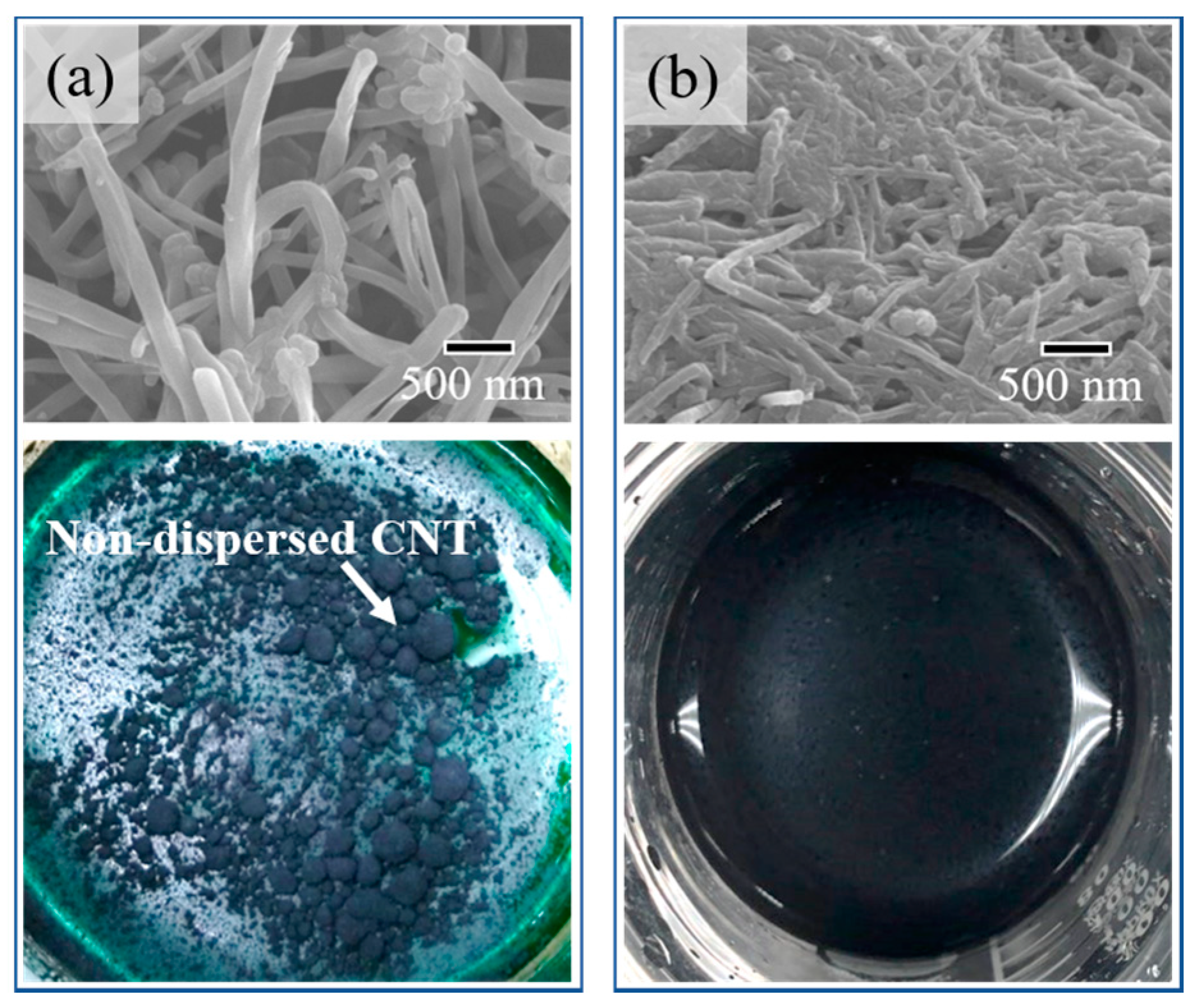
The effects of the hydrothermal treatment of CNT in mixed acid solution was investigated. Acid treatment of CNT is a widely-used method to impart hydrophilicity to CNT [29] but it has been reported that an additional dispersant should be added because it is difficult to obtain sufficient dispersibility by acid treatment alone [30]. Therefore, in this study, hydrothermal treatment of CNT was applied in a mixed acid solution, which may not require additional dispersants which may deteriorate the electrical conductivity.
The SEM images for the pristine and hydrothermal treated CNT and photographs for Ni-W plating bath with respective CNT 10 g/L added are shown in Figure 1. The pristine CNT exhibited a smooth surface with a diameter of about 100 to 200 nm, while hydrothermal treated CNT became thinner and shorter. The color of mixed acid solution used for hydrothermal treatment solution changed colorless to brown after hydrothermal treatment of CNT. The reaction may proceed as the graphite on the outermost surface of multi-layered structured CNT peels off, changing the shape by cutting the CNTs. While pristine CNT in plating bath showed aggregation and bad dispersibility, hydrothermal treated CNT was uniformly dispersed in bath.
3.2. Cathodic Polarization Measurement
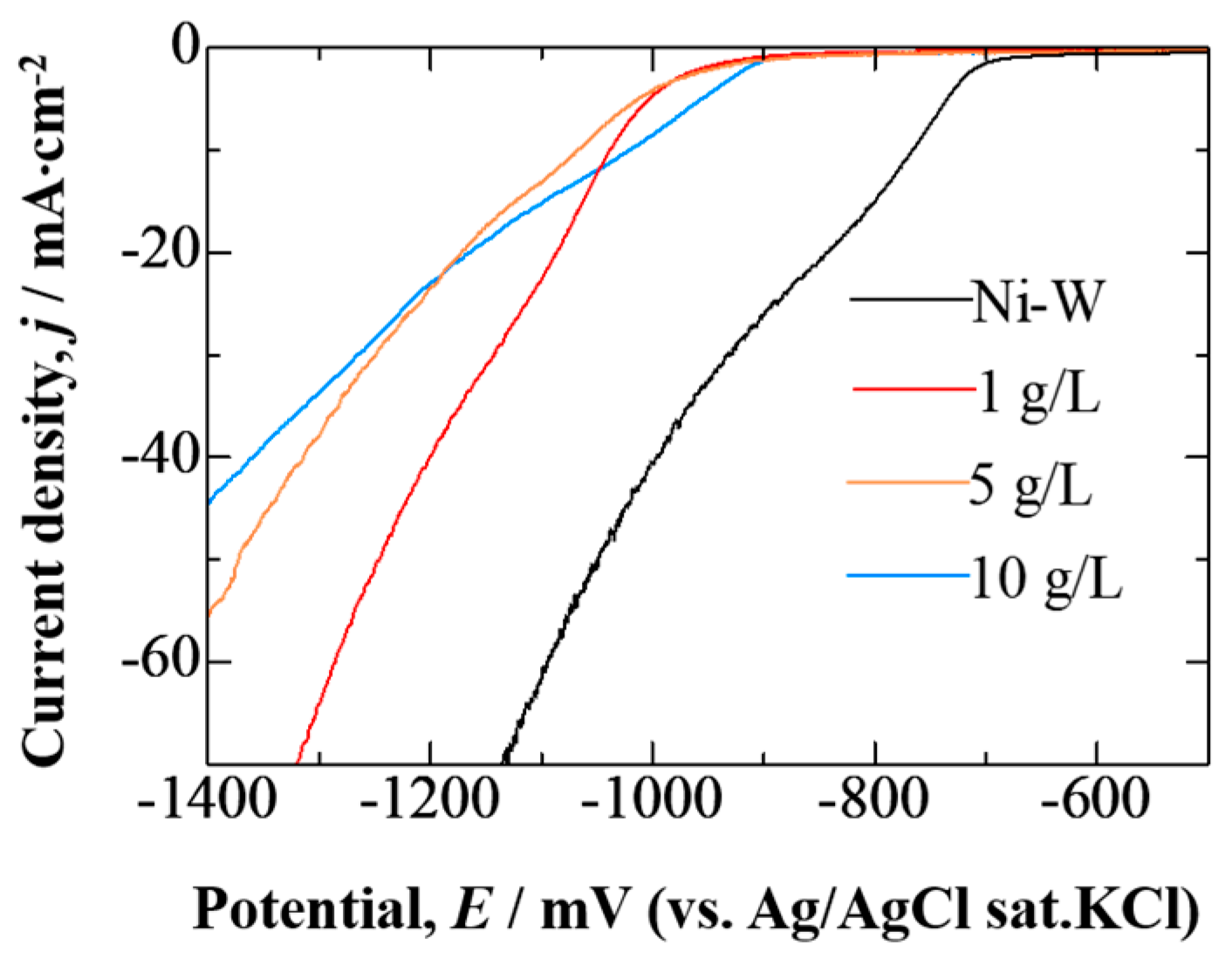
The effect of CNT addition on electrodeposition behaviors of Ni-W plating was investigated by cathodic polarization measurement. Measured cathodic polarization curves are shown in Figure 2.
For the Ni-W plating bath without CNT addition, the current density starts to increase from near −700 mV. Meanwhile the bath with hydrothermally treated CNT addition showed increased current density from −900 mV. The addition of CNT in Ni-W bath shifted the electrodeposition potential of Ni-W alloy to a more cathodic direction. At the initial stage for the electrodeposition of Ni-W/CNT composite plating, the adsorption of CNT onto cathode surface was anticipated. Adsorption of the plating additives or composite material on the cathode surface can inhibit the reduction reaction of the metal and increase the deposition overvoltage [29,31]. Although CNTs have good conductivity in the axial direction, the adsorption of CNT as axial direction in such electrodeposition condition was considered as difficult. Therefore, the CNT absorbed parallel to the cathode surface may have obstructed the reduction process of Ni-W alloy. This may shift the reduction potential of Ni-W alloy to a more cathodic potential direction. The decrease in tilt of slopes of the polarization curves along with the increase in added amount of CNT was expected to be due to the necessity of a higher overvoltage for electrodeposition of Ni-W alloy as the amount of absorbed CNT on cathode increased.
3.3. Coating Characterization
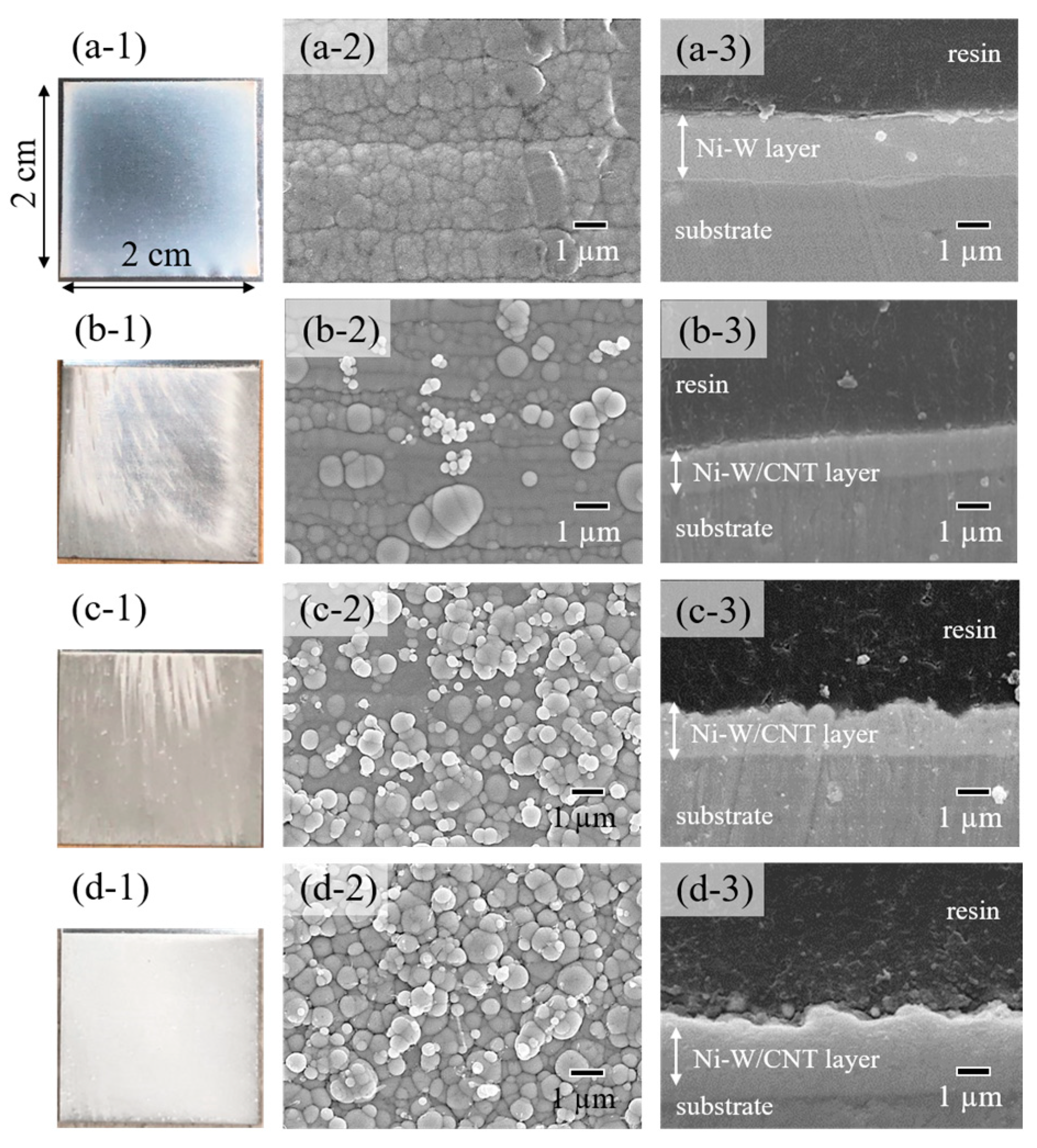
Figure 3 shows the photographs, surface and cross-sectional SEM images for Ni-W plating and Ni-W/CNT composite platings with various CNT amount. Pristine Ni-W plating showed a metallic lustered appearance (Figure 3(a-1)) and fine surface morphology (Figure 3(a-2)). As the addition amount of CNT in Ni-W plating bath increased, the metallic luster at plating surfaces gradually disappeared. In the sample prepared by adding 1 g/L of hydrothermally treated CNT, metallic luster was only partially confirmed. It was confirmed that CNT was incorporated into the non-metallic luster areas of Ni-W plating (Figure S1 in Supplementary Material). Specimens prepared by adding 5 g/L (Figure 3(c-1)) and 10 g/L (Figure 3(d-1)) of hydrothermally treated CNT showed no more metallic luster. Considered reason why the CNT distribution at on the specimen surface obtained at 1 g/L of hydrothermal CNT added bath was non-uniform is expected to be due to the insufficient CNT amount in plating bath. It was anticipated that the entire area was composed to uniform Ni-W/CNT matrix when sufficient amount of CNT was added (10 g/L).
The addition of CNT to Ni-W plating formed some particles of around 1 μm or less onto the surface observed by surface SEM images. The number of particles on surface increased as the amount of CNT added to the plating bath increased. The CNT can be observed near these particles at Ni-W/CNT composite platings prepared with plating baths contained 5 g/L (Figure 3(c-2)) and 10 g/L (Figure 3(d-2)) of CNT. Also, the increases of surface roughness by the CNT composite also can be observed in the cross-sectional SEM images.
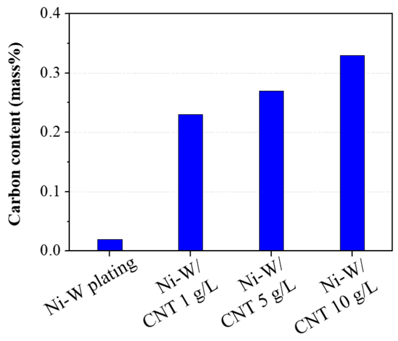
The carbon content of plating specimens measured by EMIA-510 carbon-sulfur analyzer is shown in Figure 4. Pristine Ni-W plating contained 0.02 mass.% of carbon content. The addition of non-treated CNT 1 g/L into Ni-W plating bath exhibited 0.03 mass.% carbon content (not shown in the figure) in plating, showed hardly any incorporation of CNT into the Ni-W plating. The hydrothermal treatment of CNT showed increased in a carbon content in plating close to 8 times than that of the non-treated CNT even at the same 1 g/L addition amount. The surface modification of CNT had a great influence on the CNT composite amount in the Ni-W plating. And it showed an increased carbon content in proportion to the hydrothermal treatment CNT addition amount, exhibiting the maximum carbon content of 0.33 mass.% at 10 g/L addition amount.
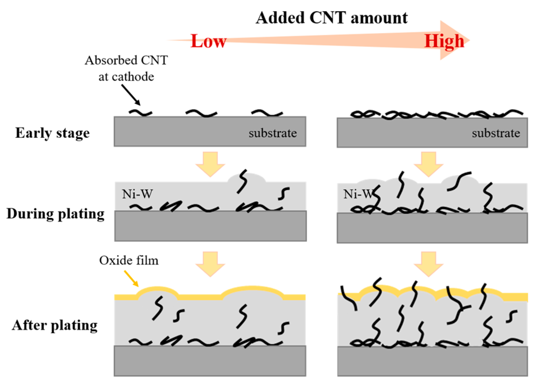
Figure 5 illustrates a schematic illustration for the layer growth model for electrodeposited Ni-W/CNT composite plating. In early stage of plating, the CNT is absorbed onto the cathode surface. The current density at cathode surface should be locally high in areas where the CNT is adsorbed, which may cause the preferential precipitation of Ni-W alloy near the CNT, resulting in a surface comprised of irregular granular shape. At high CNT addition amount, the sites of the partially high current density on the cathode surface increases due to increase in the amount of CNT adsorbed and the number of particles may increase accordingly, causing roughen surface after plating. Since the CNT protruding from the surface is a part where the oxide film of the Ni-W matrix is not formed, it is expected that the conductivity of composite plating can be improved by configuring a conductive path.
EDS element analysis and XRD measurements were performed about the specimen prepared at 10 g/L of CNT containing bath, which is a condition that a homogeneous Ni-W/CNT composite plating was obtained. The W content of the deposited Ni-W platings without CNT was about 15.2 at.% and Ni-W/CNT composite plating deposited in a bath with CNT of 10 g/L was a similar value of 15.0 at.%. Normally, the W content of Ni-W plating is affected by various plating conditions such as current density, bath pH and temperature [32,33]. Because a constant current density, bath pH and bath temperature were employed in this study regardless of the addition of CNT, no significant difference in the W content of plating was confirmed.
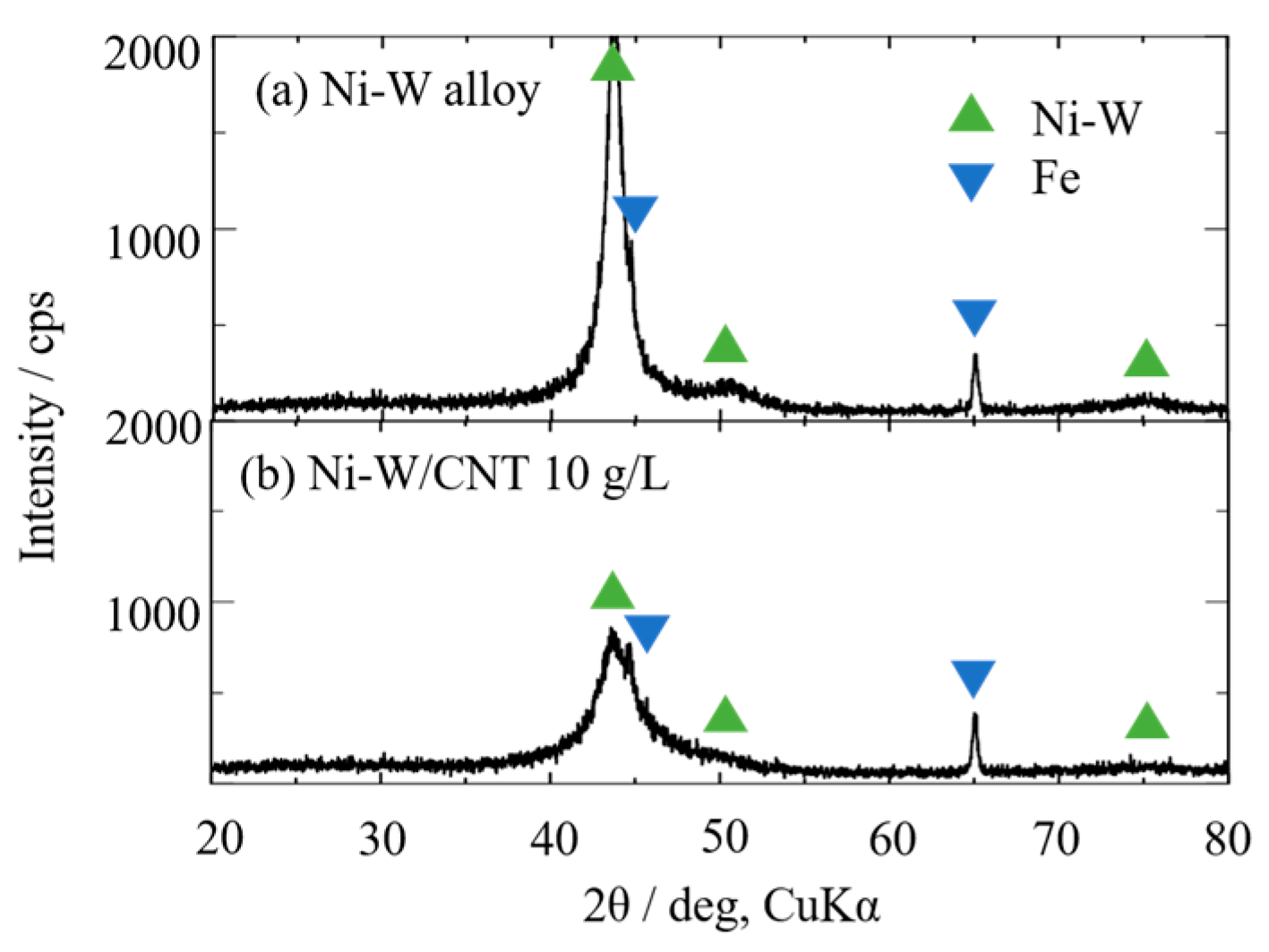
The X-ray diffraction patterns for Ni-W plating and Ni-W/CNT composite plating, prepared using baths with hydrothermally treated CNT of 10 g/L, are shown in Figure 6. Three FCC-structured Ni-W peaks, (111), (200) and (220) at near 44°, 50° and 75°, respectively were confirmed regardless of the incorporation of hydrothermally treated CNT [22]. These Ni-W peak intensity decreases in Ni-W/CNT composite plating compared to pristine Ni-W plating. The addition of CNT to the Ni-W alloy structure may cause the refinement of crystal size, which is expected to be due to the increased deposition overvoltage of the Ni-W matrix by adding CNT in the plating bath [34].
3.4. Contact Resistance
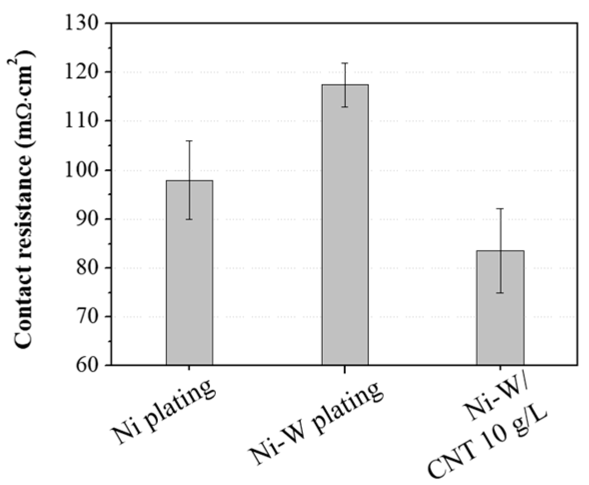
Figure 7 shows the measured contact resistance of Ni plating prepared in Watts bath, Ni-W plating and Ni-W/CNT 10 g/L composite plating. Since Ni-W/CNT composite plating prepared at the baths containing 1 g/L and 5 g/L of CNT exhibited non-uniformed appearance, contact resistance measurement was conducted about the Ni-W/CNT 10 g/L composite plating, which shows uniform appearance and CNT distribution. Ni-W plating showed higher contact resistance (average 117.5 mΩ∙cm2) than pure Ni plating (average 98.0 mΩ∙cm2), possibly due to the formation of a natural tungsten oxide on surface, which can increase contact resistance. This was similar or slightly higher value than that of austenitic stainless steel, which is mainly used as the base material of bipolar plate for PEMFC [35,36]. However, Ni-W/CNT 10 g/L composite plating (carbon content about 0.33 mass.%) showed contact resistance of average 83.6 mΩ∙cm2, approximately and 30% and 15% lower than that of pristine Ni-W plating and Ni plating, respectively. The contact resistance was expected to be decreased by incorporation of conductive CNT into the metal material [37]. Considering the relationship between the growth process of the Ni-W/CNT composite plating showed in Figure 5 and measured contact resistance results, the following speculation can be suggested. At the early stage of plating, CNT was easily adsorbed horizontally on the cathode substrate and it was considered that CNT was incorporated in the coating layer as Ni-W started precipitates in the spaces between the adsorbed CNT. During plating process, the direction of CNT could be varied in various directions because it was included in the coating layer at the same time as it contacts the substrate. Therefore, when the concentration and content of CNT was sufficiently high, there are enough CNT that were vertically included in the plating layer and serve as a conductive path between the surface oxide layer of Ni-W plating and inside of the Ni-W plating layer, resulting in lower contact resistance than Ni-W plating.
3.5. Corrosion Resistance
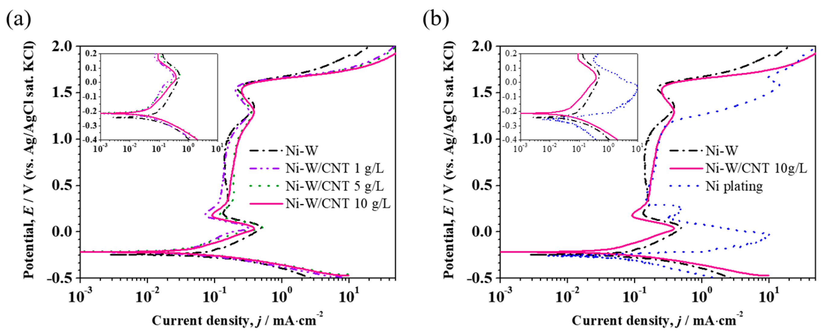
Anodic polarization curves measured at 0.5 M H2SO4 solution are plotted in Figure 8. All plating samples exhibited a typical active-passivation-transpassive behaviors. The Icorr of pristine Ni-W plating (76.13 μA∙cm−2) exhibits similar values with that of Ni plating (77.62 μA∙cm−2). However, Ni-W/CNT composite plating showed further lower Icorr than Ni and Ni-W plating. This result indicates that the corrosion resistance was improved by the addition of CNT in Ni-W plating. The same result was confirmed from the electrochemical impedance measurement result (Figure S2 in Supplementary Material) showing that Ni-W/CNT 10 g/L has better corrosion resistance than Ni and Ni-W platings. Because carbon materials are highly corrosion resistive, the composite of CNT into Ni-W plating may be effective in lowering the Icorr of plating. However, the change of the polarization curve as various amount of CNT addition was hardly observed. This result shows that the corrosion resistance of Ni-W/CNT composite plating was not directly proportional to the CNT contents. To clarify this point, we additionally prepared Ni-W/CNT composite plating specimens at the bath with 0.5, 2.5 and 7.5 g/L of CNT and performed polarization measurements. This result was presented at Figure S3 in Supplementary Material. Results showed that there is no significant difference in the Icorr at the CNT concentration of 1 g/L or more. Similarly, the Ecorr gradually shifted to noble potential direction as CNT concentration increased but no distinctive change was observed at above 1 g/L of CNT. Considered possible reason was that increased CNT content in the plating caused increase in surface roughness and enlarged surface area of platings (as shown in Figure 3), which increase the contact area with corrosive solution and offset the decreasing the Icorr by the increase in carbon content. Namely, the amount of CNT exposed at the plating surface may increase due to the increase of the CNT content in the composite plating; however, the exposed surface area of Ni-W plating also can increase. For this reason, even when the CNT content in the plating increases, it is anticipated that the corrosion resistance does not increase proportionally.
Moreover, no significant difference was observed in the passivation behaviors of Ni-W and Ni-W/CNT composite plating. This is because W content in the plating was nearly the same regardless of the existence of CNT and CNT did not affect the passivation behavior of the Ni-W plating. The Ecorr and Icorr of each plating specimens are summarized in Table 2.
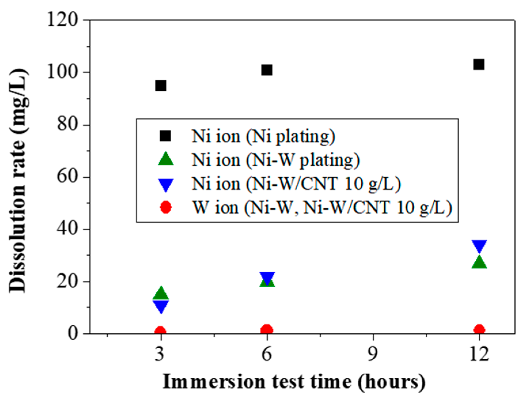
The metal dissolution rate as immersion test times are presented in Figure 9. The eluted amount of Ni ion from Ni plating was higher than that from Ni-W and Ni-W/CNT composite plating. The dissolution amount of Ni ion from Ni plating drastically increased within the first 3 h of immersion and nearly reached a plateau thereafter, implying that dissolution of Ni ion was caused by rapid corrosion in a short times. The dissolution amount of Ni ion from Ni-W plating and Ni-W/CNT composite plating exhibited further low value than Ni plating and the dissolution amount of Ni ions gradually increased as the immersion time was extended. W ion was hardly detected until 12 h for both plating. This indicates both Ni-W plating and Ni-W/CNT composite plating exhibits better corrosion resistance than Ni plating. Since W forms a stable passive film under acidic solution, W did not eluted and may remained in the form of WO3 on the surface. Similar phenomenon has ever been reported about this selective elution of Ni ions in Ni-based alloy plating such as Ni-Mo and Ni-Mo-P plating [38].
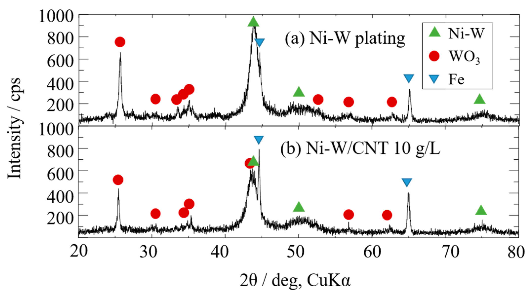
XRD analysis was performed to confirm the formation of such WO3 passive film during acid immersion test. The XRD patterns for Ni-W plating and Ni-W/CNT composite plating after 3 h immersion at 80 °C of 0.5M H2SO4 solution are shown in Figure 10. An intense reflection of WO3 appeared in both specimens, which is considered as the corrosion products of W from the Ni-W plating. The ICP measurement confirmed that only Ni ions were continuously eluted from the plating layer and the XRD result demonstrated that W remained as a WO3 state over time with the immersion test.
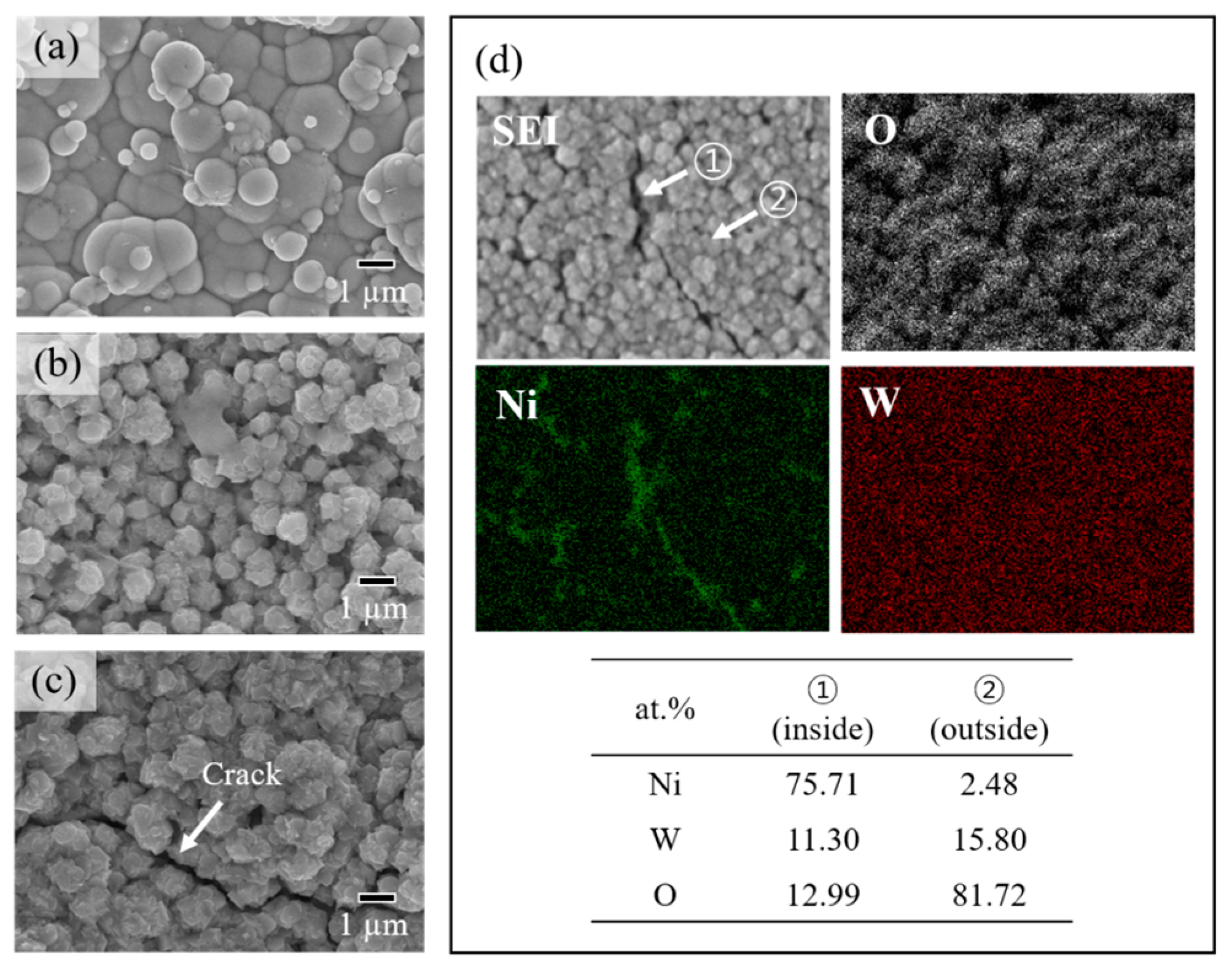
The change of surface morphologies of Ni-W/CNT 10 g/L composite plating according to immersion test times are shown in Figure 11. Globular shaped particles before immersion test gradually changed to more angled shape, which are expected to be WO3 existing at the surface after immersion of 3 h. When the coating started to corrode, Ni ions from Ni-W alloy matrix were gradually eluted but W remained and forms WO3 on top of surface after corrosion. The cracks were formed at surface after 6 h of immersion test as seen in Figure 11c.
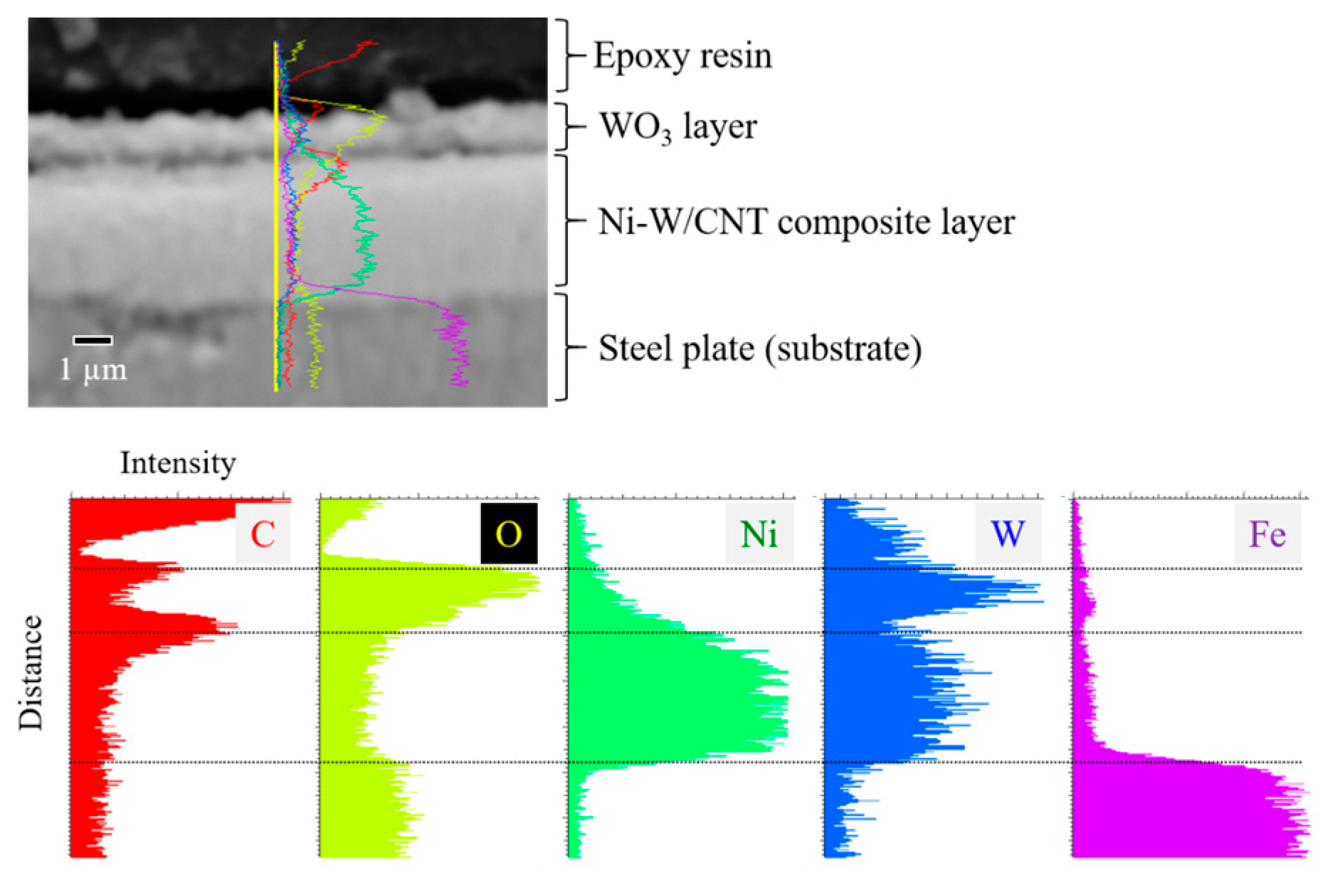
EDS elemental map images and point analysis results of inside and outside of the cracked portion after 6 h of immersion test are showed in Figure 11d. The inside of the crack showed similar elemental composition with Ni-W plating before the corrosion test, implying the existence of the uncorroded Ni-W/CNT composite layer remaining. But outside of the crack, Ni was hardly detected and the main constituent was W and O, indicating the formation of a WO3 layer. The WO3 layer formed by corrosion in acidic media seems to contribute to improving corrosion resistance by retarding additional corrosion progress, although suppression of cracks still remains to be an issue. In addition, in order to apply to bipolar plate coating, it is necessary to consider the point that formed WO3 layer on the surface can increase the interface contact resistance [39]. Cross-sectional SEM image and EDS line analysis results after immersion test 6 h are presented in Figure 12. The WO3 layer of about 1μm thickness existed on the top surface and Ni-W/CNT composite layer was remaining underneath this layer. The distribution of Ni showed a lower intensity in the outermost surface of the WO3 layer. The distribution of C in the plating layer was high between the WO3 layer and the Ni-W/CNT composite plating layer, which is presumed to be due to the CNT remaining together with the WO3 film.
4. Conclusions
In this study, Ni-W/CNT composite platings were prepared by electrodeposition and the potential as coating for PEMFC bipolar plate was examined from the viewpoint of corrosion resistance and contact resistance. Hydrophobic CNT was well dispersed through hydrothermal treatment in a mixed acid solution and can be incorporated into the Ni-W plating layer. Uniform plating surface and lower contact resistance of Ni-W/CNT composite plating were possible when the sufficient amount of hydrothermally treated CNT was added in plating bath. It is supposed that the contact resistance of the composite plating was decreased by forming a conductive path by the incorporation of CNT penetrating the surface oxide film to the inner plating layer.
Corrosion test results confirmed that Ni-W/CNT composite plating showed enhanced corrosion resistance than Ni and Ni-W plating at 0.5M H2SO4 solution. Ni-W/CNT composite plating indicates markedly lower Ni elution rate than Ni plating and W was hardly eluted from coating, remained as a WO3 layer on the surface. The formation of the WO3 layer may contribute to the improvement of the corrosion resistance and the CNT to the improvement in contact resistance of the Ni-W/CNT composite plating. The Ni-W/CNT composite plating may be a possible coating for the PEMFC bipolar plate.
Supplementary Materials
The following are available online at https://www.mdpi.com/2079-6412/10/11/1095/s1, Figure S1: Photographs and scanning electron microscopy (SEM) images for Ni-W/carbon nanotube (CNT) 1 and 5 g/L composite plating, Figure S2: Electrochemical impedance measurement results for Ni, Ni-W and Ni-W/CNT 10 g/L composite plating: (a) Nyquist plots with equivalent circuits used for data fitting; (b) fitted resistance values. (Scan range: 10 kHz to 10 mHz, amplitude: AC 10 mV, test solution: 0.5M H2SO4 and data fitting: Bio-Logic EC-LAB software was used), Figure S3: Potentiodynamic polarization measurement results for Ni-W/CNT composite platings prepared at various CNT concentration in plating bath: (a) polarization curves; (b) summarized Ecorr and Icorr as CNT concentration in bath.
Author Contributions
Conceptualization, T.H.; Data curation, T.W.; Funding acquisition, I.R.; Investigation, J.-H.P., T.W., and Y.N.; Methodology, Y.K.; Resources, Y.K.; Supervision, I.R.; Writing—original draft, J.-H.P.; Writing—review & editing, T.H. All authors have read and agreed to the published version of the manuscript.
Funding
This work was supported by “Knowledge Hub Aichi,” Priority Research Project, Japan, Aichi Prefecture Research, Development Subsidy from Aichi Prefectural Government, Japan, Japan Science and Technology Agency(JST)-OPERA Program, Japan (Grant Number: JPMJOP 1834) and research grant from Kyosho Hatta Foundation, Japan.
Acknowledgments
The authors would like to thank Nagahiro Saito for support in the lending the 4-probe contact resistance measurement apparatus (SourceMeter 2612A, Keithley).
Conflicts of Interest
The authors declare no conflict of interest.
References
- Boysen, D.A.; Uda, T.; Chisholm, C.R.I.; Haile, S.M. High-performance solid acid fuel cells through humidity stabilization. Science 2004, 303, 68–70. [Google Scholar] [CrossRef] [PubMed] [Green Version]
- Lashway, R.W. Fuel cells: The next evolution. MRS Bull. 2005, 30, 581–586. [Google Scholar] [CrossRef] [Green Version]
- Davies, D.P.; Adcock, P.L.; Turpin, M.; Rowen, S.J. Bipolar plate materials for solid polymer fuel cells. J. Appl. Electrochem. 2000, 30, 101–105. [Google Scholar] [CrossRef]
- Tawfik, H.; Hung, Y.; Mahajan, D. Metal bipolar plates for PEM fuel cell—A review. J. Power Sources 2007, 163, 755–767. [Google Scholar] [CrossRef]
- Mittal, V.O.; Kunz, H.R.; Fenton, J.M. Membrane degradation mechanisms in PEMFCs. J. Electrochem. Soc. 2007, 154, B652. [Google Scholar] [CrossRef]
- Singh, R.; Sui, P.C.; Wong, K.H.; Kjeang, E.; Knights, S.; Djilali, N. Modeling the effect of chemical membrane degradation on PEMFC performance. J. Electrochem. Soc. 2018, 165, F3328. [Google Scholar] [CrossRef] [Green Version]
- Wang, H.; Sweikart, M.A.; Turner, J.A. Stainless steel as bipolar plate material for polymer electrolyte membrane fuel cells. J. Power Sources 2003, 115, 243–251. [Google Scholar] [CrossRef]
- Wang, H.; Turner, J.A. Ferritic stainless steels as bipolar plate material for polymer electrolyte membrane fuel cells. J. Power Sources 2004, 128, 193–200. [Google Scholar] [CrossRef]
- Makkus, R.C.; Janssen, A.H.H.; de Bruijn, F.A.; Mallant, R.K.A.M. Stainless steel for cost-competitive bipolar plates in PEMFCs. Fuel Cells Bull. 2000, 3, 5–9. [Google Scholar] [CrossRef]
- El-Enin, S.A.A.; Abdel-Salam, O.E.; El-Abd, H.; Amin, A.M. New electroplated aluminum bipolar plate for PEM fuel cell. J. Power Sources 2008, 177, 131–136. [Google Scholar] [CrossRef]
- Lin, C.-H.; Tsai, S.-Y. An investigation of coated aluminium bipolar plates for PEMFC. Appl. Energy 2012, 100, 87–92. [Google Scholar] [CrossRef]
- Zhang, D.; Duan, L.; Guo, L.; Wang, Z.; Zhao, J.; Tuan, W.-H.; Niihara, K. TiN-coated titanium as the bipolar plate for PEMFC by multi-arc ion plating. Int. J. Hydrogen Energy 2011, 36, 9155–9161. [Google Scholar] [CrossRef]
- Wang, S.-H.; Peng, J.; Lui, W.-B.; Zhang, J.-S. Performance of the gold-plated titanium bipolar plates for the light weight PEM fuel cells. J. Power Sources 2006, 162, 486–491. [Google Scholar] [CrossRef]
- Tian, R.; Sun, J.; Wang, L. Plasma-nitrided austenitic stainless steel 316L as bipolar plate for PEMFC. Int. J. Hydrogen Energy 2006, 31, 1874–1878. [Google Scholar] [CrossRef]
- Han, D.-H.; Hong, W.-H.; Choi, H.S.; Lee, J.J. Inductively coupled plasma nitriding of chromium electroplated AISI 316L stainless steel for PEMFC bipolar plate. Int. J. Hydrogen Energy 2009, 34, 2387–2395. [Google Scholar] [CrossRef]
- Lee, S.-J.; Huang, C.-H.; Chen, Y.-P. Investigation of PVD coating on corrosion resistance of metallic bipolar plates in PEM fuel cell. J. Mater. Process. Technol. 2003, 140, 688–693. [Google Scholar] [CrossRef]
- Fetohi, A.E.; Hameed, R.M.A.; El-Khatib, K.M.; Souaya, E.R. Ni–P and Ni–Co–P coated aluminum alloy 5251 substrates as metallic bipolar plates for PEM fuel cell applications. Int. J. Hydrogen Energy 2012, 37, 7677–7688. [Google Scholar] [CrossRef]
- Gamboa, S.A.; Gonzalez-Rodriguez, J.G.; Valenzuela, E.; Campillo, B.; Sebastian, P.J.; Reyes-Rojas, A. Evaluation of the corrosion resistance of Ni–Co–B coatings in simulated PEMFC environment. Electrochim. Acta 2006, 51, 4045–4051. [Google Scholar] [CrossRef]
- Fu, Y.; Hou, M.; Xu, H.; Hou, Z.; Ming, P.; Shao, Z.; Yi, B. Ag–polytetrafluoroethylene composite coating on stainless steel as bipolar plate of proton exchange membrane fuel cell. J. Power Sources 2008, 182, 580–584. [Google Scholar] [CrossRef]
- Wang, S.-H.; Peng, J.; Lui, W.-B. Surface modification and development of titanium bipolar plates for PEM fuel cells. J. Power Sources 2006, 160, 485–489. [Google Scholar] [CrossRef]
- Elias, L.; Hegde, A.C. Electrodeposition of laminar coatings of Ni–W alloy and their corrosion behaviour. Surf. Coat. Technol. 2015, 283, 61–69. [Google Scholar] [CrossRef]
- Juškėnas, R.; Valsiūnas, I.; Pakštas, V.; Giraitis, R. On the state of W in electrodeposited Ni–W alloys. Electrochim. Acta 2009, 54, 2616–2620. [Google Scholar] [CrossRef]
- Aljohani, T.A.; Hayden, B.E. A simultaneous screening of the corrosion resistance of Ni–W thin film alloys. Electrochim. Acta 2013, 111, 930–936. [Google Scholar] [CrossRef]
- Sriraman, K.R.; Sundara Raman, S.G.; Seshadri, S.K. Synthesis and evaluation of hardness and sliding wear resistance of electrodeposited nanocrystalline Ni–Fe–W alloys. Mater. Sci. Technol. 2006, 22, 14–20. [Google Scholar] [CrossRef]
- Mbugua Nyambura, S.; Kang, M.; Zhu, J.; Liu, Y.; Zhang, Y.; Ndiithi, N.J. Synthesis and Characterization of Ni–W/Cr2O3 Nanocomposite Coatings Using Electrochemical Deposition Technique. Coatings 2019, 9, 815. [Google Scholar] [CrossRef] [Green Version]
- Marinho, B.; Ghislandi, M.; Tkalya, E.; Koning, C.E.; de With, G. Electrical conductivity of compacts of graphene, multi-wall carbon nanotubes, carbon black and graphite powder. Powder Technol. 2012, 221, 351–358. [Google Scholar] [CrossRef]
- Goto, Y.; Kamebuchi, Y.; Hagio, T.; Kamimoto, Y.; Ichino, R.; Bessho, T. Electrodeposition of copper/carbonous nanomaterial composite coatings for heat-dissipation materials. Coatings 2018, 8, 5. [Google Scholar] [CrossRef] [Green Version]
- Kamimoto, Y.; Okura, S.; Hagio, T.; Wada, T.; Tanaka, H.; Hara, H.; Deevanhxay, P.; Ichino, R. Nickel–carbon composite plating using a Watts nickel electroplating bath. SN Appl. Sci. 2020, 2, 170. [Google Scholar] [CrossRef] [Green Version]
- Shi, L.; Sun, C.F.; Gao, P.; Zhou, F.; Liu, W.M. Electrodeposition and characterization of Ni–Co–carbon nanotubes composite coatings. Surf. Coat. Technol. 2006, 200, 4870–4875. [Google Scholar] [CrossRef]
- Arai, S.; Fujii, J. Electroless deposition of silver on multiwalled carbon nanotubes using iodide bath. J. Electrochem. Soc. 2011, 158, D506–D510. [Google Scholar] [CrossRef] [Green Version]
- Arai, S.; Saito, T.; Endo, M. Cu–MWCNT composite films fabricated by electrodeposition. J. Electrochem. Soc. 2010, 157, D147–D153. [Google Scholar] [CrossRef] [Green Version]
- Kumar, K.A.; Kalaignan, G.P.; Muralidharan, V.S. Pulse electrodeposition and characterization of nano Ni–W alloy deposits. Appl. Surf. Sci. 2012, 259, 231–237. [Google Scholar] [CrossRef]
- Wasekar, N.P.; Hebalkar, N.; Jyothirmayi, A.; Lavakumar, B.; Ramakrishna, M.; Sundararajan, G. Influence of pulse parameters on the mechanical properties and electrochemical corrosion behavior of electrodeposited Ni-W alloy coatings with high tungsten content. Corros. Sci. 2020, 165, 108409. [Google Scholar] [CrossRef]
- Fan, Y.; He, Y.; Luo, P.; Shi, T.; Li, H. Pulse current electrodeposition and characterization of Ni-W-MWCNTs nanocomposite coatings. J. Electrochem. Soc. 2015, 162, D270. [Google Scholar] [CrossRef]
- De Las Heras, N.; Roberts, E.P.L.; Langton, R.; Hodgson, D.R. A review of metal separator plate materials suitable for automotive PEM fuel cells. Energy Environ. Sci. 2009, 2, 206–214. [Google Scholar] [CrossRef]
- Asri, N.F.; Husaini, T.; Sulong, A.B.; Majlan, E.H.; Daud, W.R.W. Coating of stainless steel and titanium bipolar plates for anticorrosion in PEMFC: A review. Int. J. Hydrogen Energy 2017, 42, 9135–9148. [Google Scholar] [CrossRef]
- Oluwalowo, A.; Nguyen, N.; Zhang, S.; Park, J.G.; Liang, R. Electrical and thermal conductivity improvement of carbon nanotube and silver composites. Carbon 2019, 146, 224–231. [Google Scholar] [CrossRef]
- Rajaei, V.; Rashtchi, H.; Raeissi, K.; Shamanian, M. The study of Ni-based nano-crystalline and amorphous alloy coatings on AISI 304 stainless steel for PEM fuel cell bipolar plate application. Int. J. Hydrogen Energy 2017, 42, 14264–14278. [Google Scholar] [CrossRef]
- Mendizabal, L.; Oedegaard, A.; Kongstein, O.E.; Lædre, S.; Walmsley, J.; Barriga, J.; Gonzalez, J.J. TaNX coatings deposited by HPPMS on SS316L bipolar plates for polymer electrolyte membrane fuel cells: Correlation between corrosion current, contact resistance and barrier oxide film formation. Int. J. Hydrogen Energy 2017, 42, 3259–3270. [Google Scholar] [CrossRef]
Figure 1.
Scanning electron microscopy (SEM) images of CNT and optical photographs for Ni-W plating bath with addition of CNT 10 g/L: (a) pristine CNT; (b) hydrothermally treated CNT.
Figure 1.
Scanning electron microscopy (SEM) images of CNT and optical photographs for Ni-W plating bath with addition of CNT 10 g/L: (a) pristine CNT; (b) hydrothermally treated CNT.

Figure 2.
Cathodic polarization curves for Ni-W plating bath and hydrothermally treated CNT added Ni-W plating bath. Scan rate: 5 mV∙s−1 under continuous magnetic agitation at 500 rpm.
Figure 2.
Cathodic polarization curves for Ni-W plating bath and hydrothermally treated CNT added Ni-W plating bath. Scan rate: 5 mV∙s−1 under continuous magnetic agitation at 500 rpm.

Figure 3.
Optical photographs, surface and cross-sectional SEM images: (a) pristine Ni-W plating; (b) Ni-W/CNT 1 g/L; (c) Ni-W/CNT 5 g/L; (d) Ni-W/CNT 10 g/L.
Figure 3.
Optical photographs, surface and cross-sectional SEM images: (a) pristine Ni-W plating; (b) Ni-W/CNT 1 g/L; (c) Ni-W/CNT 5 g/L; (d) Ni-W/CNT 10 g/L.

Figure 4.
Carbon content of Ni-W and Ni-W/CNT composite plating measured by EMIA-510 carbon-sulfur analyzer. All added CNT was hydrothermally treated in mixed acid solution.
Figure 4.
Carbon content of Ni-W and Ni-W/CNT composite plating measured by EMIA-510 carbon-sulfur analyzer. All added CNT was hydrothermally treated in mixed acid solution.

Figure 5.
Schematic illustrations of Ni-W/CNT composite layer growth as a function of CNT addition amount in Ni-W plating bath.
Figure 5.
Schematic illustrations of Ni-W/CNT composite layer growth as a function of CNT addition amount in Ni-W plating bath.

Figure 6.
X-ray diffraction (XRD) patterns: (a) Ni-W plating; (b) Ni-W/CNT 10 g/L composite plating. The W content of each plating: 15.2 and 15.0 at.%, respectively.
Figure 6.
X-ray diffraction (XRD) patterns: (a) Ni-W plating; (b) Ni-W/CNT 10 g/L composite plating. The W content of each plating: 15.2 and 15.0 at.%, respectively.

Figure 7.
Contact resistance of Ni, Ni-W and Ni-W/CNT 10 g/L composite plating measured by 4-probe measurement method. (Number of measurements: 5 different areas for each sample).
Figure 7.
Contact resistance of Ni, Ni-W and Ni-W/CNT 10 g/L composite plating measured by 4-probe measurement method. (Number of measurements: 5 different areas for each sample).

Figure 8.
Anodic polarization curves measured at 0.5M H2SO4 solution with scan rate of 1 mV∙s−1: (a) Ni-W plating and Ni-W/CNT composite plating with various CNT contents; (b) comparison with Ni plating.
Figure 8.
Anodic polarization curves measured at 0.5M H2SO4 solution with scan rate of 1 mV∙s−1: (a) Ni-W plating and Ni-W/CNT composite plating with various CNT contents; (b) comparison with Ni plating.

Figure 9.
Dissolution amount of metal ions according to immersion test times measured by ICP-AES.

Figure 10.
XRD diffractograms after 3 h of immersion test in 0.5 M H2SO4 solution with 80 °C: (a) Ni-W plating; (b) Ni-W/CNT 10 g/L composite plating.
Figure 10.
XRD diffractograms after 3 h of immersion test in 0.5 M H2SO4 solution with 80 °C: (a) Ni-W plating; (b) Ni-W/CNT 10 g/L composite plating.

Figure 11.
Observation for corrosion progression of Ni-W/CNT composite plating according to immersion test time: (a) surface morphologies of Ni-W/CNT 10 g/L composite plating before immersion test; (b) after 3 h; (c) after 6 h; (d) elemental map images with EDS point analysis results at inside of crack portion (point 1), outside of crack (point 2) after immersion test 6 h.

Figure 12.
Cross-sectional SEM image and energy-dispersive spectroscopy (EDS) line analysis results after immersion test 6 h.
Figure 12.
Cross-sectional SEM image and energy-dispersive spectroscopy (EDS) line analysis results after immersion test 6 h.


Table 1.
Bath compositions for Ni-W and Ni-W/ carbon nanotube (CNT) composite plating.
| Reagent | Concentration |
|---|---|
| (NH4)3C6H5O7 | 0.3 mol/L |
| NiSO4 | 0.1 mol/L |
| Na2WO4 | 0.2 mol/L |
| Hydrothermal treated CNT | 0, 1, 5, 10 g/L |
| pH | 7.0 |
| Temperature | 40 °C |
Table 2.
Anodic polarization parameters for the pristine Ni plating, Ni-W plating and Ni-W/CNT 1, 5 and 10 g/L composite plating in 0.5M H2SO4 solution.
Table 2.
Anodic polarization parameters for the pristine Ni plating, Ni-W plating and Ni-W/CNT 1, 5 and 10 g/L composite plating in 0.5M H2SO4 solution.
| Specimens | Ecorr [mV] | Icorr [μA∙cm−2] |
|---|---|---|
| Ni plating | −258.23 | 77.62 |
| Ni-W plating | −242.73 | 76.13 |
| Ni-W/CNT 1 g/L | −218.99 | 39.32 |
| Ni-W/CNT 5 g/L | −211.01 | 41.45 |
| Ni-W/CNT 10 g/L | −211.83 | 40.78 |
Publisher’s Note: MDPI stays neutral with regard to jurisdictional claims in published maps and institutional affiliations. |
© 2020 by the authors. Licensee MDPI, Basel, Switzerland. This article is an open access article distributed under the terms and conditions of the Creative Commons Attribution (CC BY) license (http://creativecommons.org/licenses/by/4.0/).
Share and Cite
MDPI and ACS Style
Park, J.-H.; Wada, T.; Naruse, Y.; Hagio, T.; Kamimoto, Y.; Ryoichi, I. Electrodeposition of Ni-W/CNT Composite Plating and Its Potential as Coating for PEMFC Bipolar Plate. Coatings 2020, 10, 1095. https://doi.org/10.3390/coatings10111095
AMA Style
Park J-H, Wada T, Naruse Y, Hagio T, Kamimoto Y, Ryoichi I. Electrodeposition of Ni-W/CNT Composite Plating and Its Potential as Coating for PEMFC Bipolar Plate. Coatings. 2020; 10(11):1095. https://doi.org/10.3390/coatings10111095
Chicago/Turabian StylePark, Jae-Hyeok, Tatsuya Wada, Yuto Naruse, Takeshi Hagio, Yuki Kamimoto, and Ichino Ryoichi. 2020. "Electrodeposition of Ni-W/CNT Composite Plating and Its Potential as Coating for PEMFC Bipolar Plate" Coatings 10, no. 11: 1095. https://doi.org/10.3390/coatings10111095
Note that from the first issue of 2016, this journal uses article numbers instead of page numbers. See further details here.