Continuous Tip Widening Technique for Roll-to-Roll Fabrication of Dry Adhesives


1
School of Mechanical Engineering, Kyungpook National University, Daegu 41566, Korea
2
Department of Mechanical Engineering, Ulsan National Institute of Science and Technology, Ulsan 34130, Korea
*
Authors to whom correspondence should be addressed.
Coatings 2018, 8(10), 349; https://doi.org/10.3390/coatings8100349
Submission received: 23 August 2018
/
Revised: 24 September 2018
/
Accepted: 28 September 2018
/
Published: 30 September 2018
Abstract
:In this study, we reported continuous partial curing and tip-shaped modification methods for continuous production of dry adhesive with microscale mushroom-shaped structures. Typical fabrication methods of dry adhesive with mushroom-shaped structures are less productive due to the failure of large tips on pillar during demolding. To solve this problem, a typical pillar structure was fabricated through partial curing, and tip widening was realized through applying the proper pressure. Polyurethane acrylate was used in making the mushroom structure using two-step UV-assisted capillary force lithography (CFL). To make the mushroom structure, partial curing was performed on the micropillar, followed by tip widening. Dry adhesives with properties similar to those of typical mushroom-shaped dry adhesives were fabricated with reasonable adhesion force using the two-step UV-assisted CFL. This production technology was applied to the roll-to-roll process to improve productivity, thereby realizing continuous production without any defects. Such a technology is expected to be applied to various fields by achieving the productivity improvement of dry adhesives, which is essential for various applications.
1. Introduction
Microstructure-based dry adhesives, which were inspired by the feet of gecko lizards and beetles, have attracted attention in various applications due to their strong adhesion, repeatability, reversibility, and self-cleaning properties [1,2,3,4,5,6,7,8,9,10,11,12,13]. They are applied to a transfer or fixing device, such as a glass substrate and silicon wafer, and an attempt has been made to replace the existing electrostatic or vacuum chuck [8,14]. These dry adhesives are typically made from polymeric pillars of the size of a few hundred nanometers to tens of micrometers, and the tip of the pillar is shaped like a spatula or mushroom to maximize its adhesive properties [15,16,17]. Generally, dry adhesive production method is a molding technique, such as soft lithography; thus, manufacturing the aforementioned size structure is easy [4]. However, constructing a precisely designed tip shape on a master can be a complex process [4,8,18]. For example, in the case of producing mushroom-like microstructure dry adhesives on a master, the tip must be formed inside the silicon wafer to form a wide tip on the surface of the dry adhesive when replicated. This tip plays an important role in securing the adhesion; this role has been confirmed in studies that handle the comparison of adhesive strengths according to various tip shapes [15]. Based on the literature, a dry adhesive with a thin and wide area tip has a high adhesive strength, and a complicated process is required to produce a master for such a dry adhesive. An example of fabricating a master with a wide tip is to use the footing effect that occurs in the etch stop layer during deep RIE (Reactive Ion Etching) process [19]. If etching is performed to a thickness over the working depth simply by using the SOI (Silicon on insulator) wafer, then the etching ion does not proceed in the depth direction in the SiO2 layer but is etched laterally. This process is called the footing effect, in which forming a wide tip on a master is relatively easy. However, this method has a disadvantage; it cannot precisely control the thickness or size of the tip. To solve this problem, the tip precisely fabricated on the wafer surface through the surface micromachining and the tip buried masters are manufactured by fusion bonding between the surface-machined wafers and bare wafer [5,8,18]. The fabricated master mold can be used to produce a dry adhesive after a simple release layer treatment; however, it is difficult to apply in a continuous production using a roll-to-roll process due to poor demolding (e.g., tip tearing depending on the polymer used) [20]. Particularly, in the roll-to-roll process, which can only use a flexible polymer mold, the breakage of the tip during demolding becomes evident. Therefore, the productivity should be improved through new methods. In the present work, we introduce an advanced UV molding technique called two-step UV-assisted capillary force lithography (CFL) to produce a mushroom-shaped dry adhesive without special demolding failure. This method can be applied to the roll-to-roll-based apparatus without any changes; thus, it is applied to the prototype roll-to-roll apparatus to test the mass production possibility. Moreover, the pull-off strength of the fabricated dry adhesive is measured. The measured adhesive strength of approximately 9.5 N/cm2 is slightly lower than that of dry adhesives made by typical one-step molding [8]; nevertheless, this value is appropriate for application. In addition, higher adhesion can be achieved if the tip size can be widened in a future optimization process. The study of tip widening using partial curing has been experimentally proven in previous studies [21]. In this paper, we intend to implement this process continuously.
2. Materials and Methods
Polyurethane acrylate (PUA): PUA is an ultraviolet ray curable material composed of prepolymer with acrylate group, a photoinitiator, a crosslinker and a release agent. The PUA was dropped onto a master mold with pillar shaped microstructures, which were fabricated by surface micromachining. A PET (polyethylene terephthalate) film as supporting layer was covered on the dropped PUA, followed by UV exposure for 40 s (wavelength = 250–400 nm, dose = 100 mJ/cm2). After UV exposure, the PET film was peeled off from the master with cured PUA structure.
Partially cured micropillar: Our fabrication method was based on the two-step process of capillary UV molding and additional tip shape modification. For the fabrication of PUA partially cured micropillars, the polydimethylsiloxane (PDMS) mold with micro holes was used with enough window for partial curing time. Then, the PUA resin was partially cured by UV exposure for 15–20 s (wavelength = 365 nm, intensity = 100 mW/cm2).
Tip widening: The film was placed on the top of the partially cured pillar, and further curing was performed for 30 s while applying the appropriate pressure of 20–30 kPa (wavelength = 365 nm, intensity = 500 mW/cm2). For a uniform pressure distribution, a thin PDMS block was placed as a buffer on top of the PET film prior to the application of pressure.
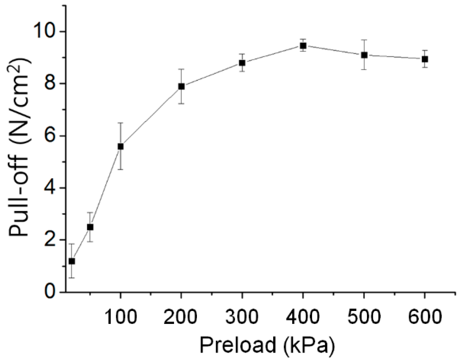
Measurement of pull-off force: We measured pull-off force and durability with custom built equipment [8]. To measure normal adhesion force between fabricated dry adhesive and target smooth substrate, the smooth substrate was made with a glass sample and was moved vertically with speed of 3 mm/s by a step motor connected crank. The device is equipped with a load cell capable of measuring the load in the z-axis direction, allowing measurement of the pull-off force including the preload. Pull-off forces were measured for various preloads, and marathon tests were conducted at the speed of 50 cycles per minute and 40 N/cm2 preload.
3. Results and Discussion
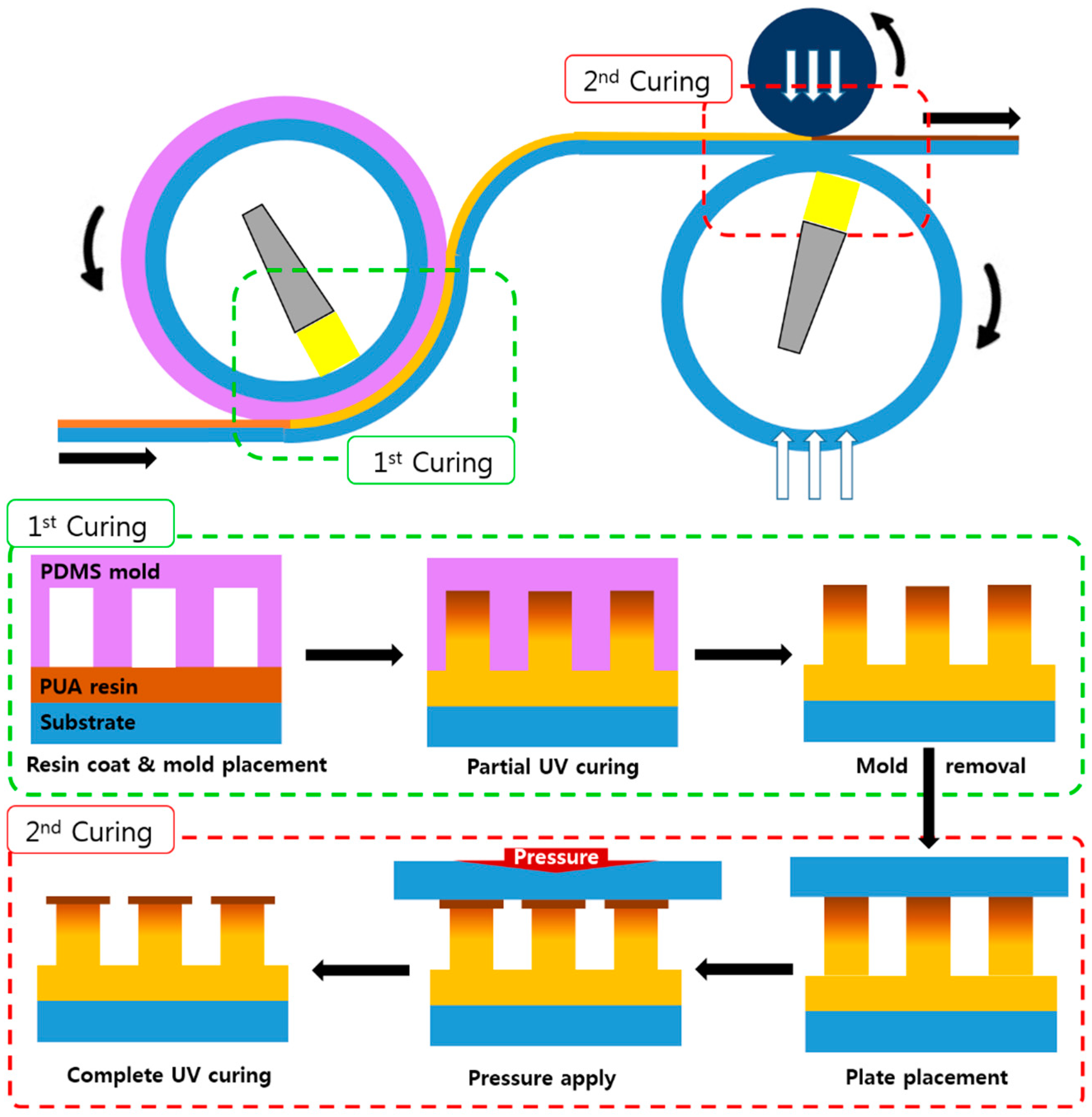
Figure 1 shows the schematic of the two-step UV-assisted CFL and that of a continuous production apparatus. PDMS is a known porous material. In this study, PDMS was used to induce partial curing and fabricate hierarchical structures. In the case of the PDMS mold, the surface of the molded polymer film was exposed to air that was permeated through a porous PDMS mold. The trapped or permeated oxygen inhibited UV curing by scavenging radicals generated from the photoinitiator by UV [22]. Thus, the surface of the PUA resin in contact with the air remained tacky, whereas the resin beneath the surface cured completely. Some pre-dissolved oxygen existed in the liquid resin. This oxygen was rapidly consumed under UV exposure due to high mobility and reactivity of oxygen with a large number of initial radicals. Therefore, the formation of a tacky surface could be attributed to the diffusion of oxygen that was trapped in the mold cavity or permeated out of the mold. In a previous research on two-step CFL, micro/nano hierarchical structure was fabricated using a nano-structured mold after the microstructure fabrication [22]. A microstructure was fabricated, and a wide tip was then formed on the partially cured microstructure by pressurization using a flat substrate. The tip of the microstructure was widened by simply using a glass substrate, and the low adhesion between glass and PUA enabled the production of a mushroom structure without any surface treatment. After the process proof at the wafer level, this principle was used to realize continuous production using a roll-to-roll apparatus. The roll-to-roll apparatus was divided into microstructure and tip production sections. In the microstructure production section, a PDMS negative mold was attached to the roll, whereas the tip production section is composed of a simple quartz cylinder and a urethane roll. The partial curing phenomenon in the microstructure fabrication was theoretically predictable. On the basis of the literature, the oxygen saturation inside the polymer resin, which depends on the depth of the resin from the surface, can be expressed as [22]:
where is the oxygen concentration in the cavities, is the oxygen diffusivity coefficient in the polymer layer, is the surface concentration of oxygen, L is the depth of the cured polymer resin, x is distance from free-surface between air and resin. When the appropriate constants were substituted for this equation (k = 1, = 10−12 m2·s−1), the penetration of oxygen during the microstructure fabrication of PUA resin proceeded from the resin surface to approximately 4–5 μm. That is, the upper 4 μm of the microstructure remained in a state capable of subsequent patterning while still maintaining a non-cured tacky surface. The tip structure to be fabricated through this study was expected to express sufficiently by this partial curing process, in which the diameter was approximately 1 μm larger than the micropillar and the thickness was approximately 500 nm. To fabricate an appropriate partially cured micropillar, the intensity of UV LED at 365 nm wavelength was adjusted to 100 mW/cm2 and exposed for a suitable time (15–20 s) to fabricate a microstructure whose surface remained tacky.
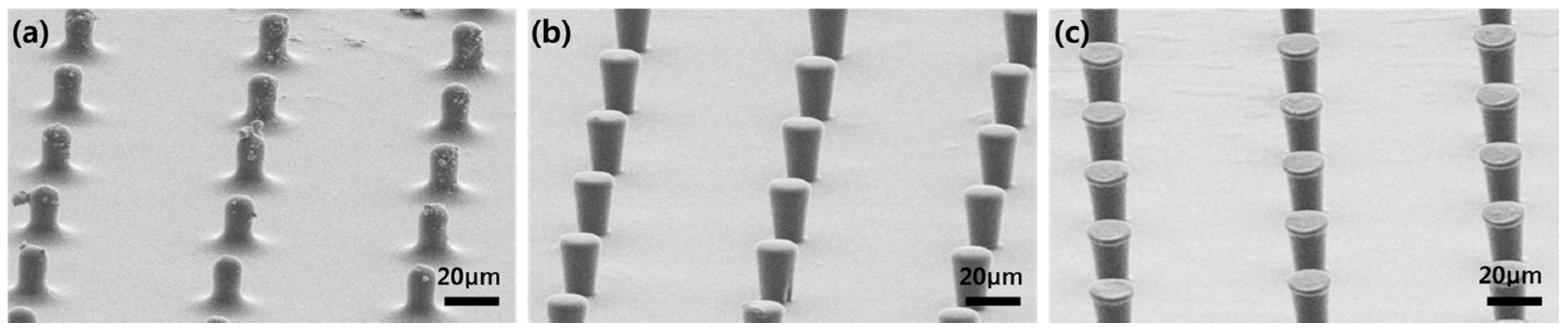
Thereafter, various pressures were applied to the tip widening. As a result, suitable pressure (25 kPa) was identified, and the mushroom structure was constructed. As shown in Figure 2, an extremely low pressure (10 kPa) did not sufficiently expand the tip, and an extremely high pressure (40 kPa) caused columnar deformation or collapse. At lower pressures, the not fully cured resin is irregularly wetted, clumped like contaminants, or wicked down the pillar to create an unusual pillar shape. (Figure 2a) To solve this problem, a structure with a wide tip is successfully fabricated by making perfect contact with high pressure. The column part is already cured and fixed to its own shape differently from the tacky surface of the tip part, but since it is not over-cured, it is possible to deform a little by strong pressure and exposure so that the upper part becomes a little wider column structure after the pressure applying process. The production speed is determined by the type of material, the time to produce partial curing, and the time required to derive the structural change through pressure. In this work, production speed was about 100 cm2/min. We expect this result to be improved through future optimization studies.
After the appropriate pressurization, the mushroom structure was fabricated through second exposure, and the pull-off strength of the sample was measured by a typical adhesion measurement. The preload was fixed to 40 N, and the repeated adhesion test was performed using a load cell. We predicted the life of fabricated dry adhesive through the analysis of the tendency of decrease in adhesive force by using a marathon test equipment made from a simple crank system. The marathon test was conducted in a normal laboratory environment and not in a clean room; thus, various contaminants may be found.
Figure 3 shows the pull-off strength measurement results of the prepared dry adhesive samples. The measured adhesive strength was lower than that of the mushroom-shaped wide-tip microstructures (~20 N/cm2) produced by conventional methods because forming a wide and thin tip necessary for strong adhesion was impossible, which may be solved by optimization of the subsequent process.
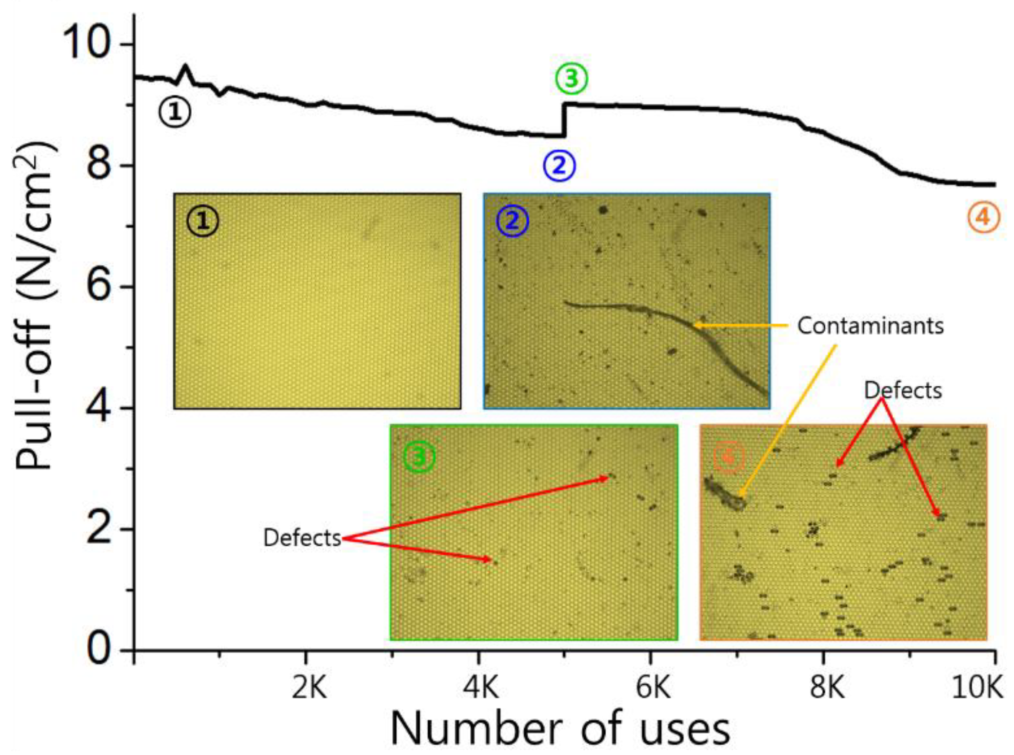
Selection of the resin, optimization of the primary curing time and UV intensity, the amount of pressure applied during the secondary curing, and the curing time should be considered for the production of a wide tip. Figure 4 shows the results of the marathon test for the durability of dry adhesives. The adhesives initially showed a maximum adhesive strength of 9.5 N/cm2 and a 10% decrease in adhesion after repeated use of 5000 times. As shown in Figure 4, numerous contaminants were found on the dry adhesive surface observed after 5000 uses, and several defects were also found. Although not many, defects were present where the tip portion was torn out or the microstructures were matted together. Usually, the tip is torn rather than the column is broken. This can be seen as fatigue failure and breakage at the tip connection part where the greatest stress concentration occurs. After using the test for 5000 cycles, the surfaces of the dry adhesive and the substrate were cleaned using a commercial pressure sensitive adhesive tape. Subsequently, the recovered adhesive strength was 94% of the original adhesive strength. As shown in Figure 4, all of the contaminants, except for defects, were removed through the cleaning process, and some of the matting was recovered during the cleaning process using the adhesive tape, resulting in a slight increase in the adhesion. The subsequent 5000 additional adhesion tests resulted in the same level of adhesion of the contaminants and additional defects. However, the degradation tendency was considerably better than that of dry adhesives with conventional wide tips. Adhesive strength and lifetime are inversely related to each other; thus, the fabricated dry adhesives are likely to be fully utilized in applications where they have to be used for a long period of time with proper adhesive strength. The marathon test result shows reasonable adhesive strength of up to 10,000 times, and the test is expected to be used in various fields.
4. Conclusions
We developed a continuous production technology of mushroom-shaped dry adhesives by utilizing the two-step UV-assisted CFL. The mushroom shape was produced by continuously producing the micropillars and by applying pressure to the partially cured micropillars, the tip portion was widened, and the fabricated dry adhesives exhibited an adhesive strength of 9.5 N/cm2 on the glass substrate. In addition, the dry adhesives were excellent in terms of durability due to their shape characteristics and exhibited an adhesive strength of approximately 80% even in a marathon test of 10,000 times. The complicated mold-making process was necessary in the conventional continuous production technique. However, this process could be omitted to reduce the production cost and increase production efficiency. Furthermore, if the productivity is secured with the performance of a reasonable dry adhesive, then it can be applied to various application fields.
Author Contributions
Conceptualization, M.K.; Methodology, H.E.J. and M.K.; Experiments, H.Y. and S.H.L.; Writing-Original Draft Preparation, S.H.L. and M.K.; Writing-Review & Editing, M.K., H.E.J. and C.W.P.; Supervision, M.K. and H.E.J.; Funding Acquisition, M.K.
Funding
This work was supported by the National Research Foundation of Korea (2016R1A2B4007858) funded by the Korean Government (MSIP).
Acknowledgments
The authors thank Jeong Hyeon Lee for his technical support.
Conflicts of Interest
The authors declare no conflicts of interest.
References
- Autumn, K. The gecko effect: Dynamic dry adhesive microstructures. Am. Zool. 2001, 41, 1382–1383. [Google Scholar]
- Gorb, S.N.; Varenberg, M. Mushroom-shaped geometry of contact elements in biological adhesive systems. J. Adhes. Sci. Technol. 2007, 21, 1175–1183. [Google Scholar] [CrossRef]
- Varenberg, M.; Pugno, N.M.; Gorb, S.N. Spatulate structures in biological fibrillar adhesion. Soft Matter 2010, 6, 3269–3272. [Google Scholar] [CrossRef]
- Kwak, M.K.; Pang, C.; Jeong, H.E.; Kim, H.N.; Yoon, H.; Jung, H.S.; Suh, K.Y. Towards the next level of bioinspired dry adhesives: New designs and applications. Adv. Funct. Mater. 2011, 21, 3606–3616. [Google Scholar] [CrossRef]
- Yi, H.; Hwang, I.; Lee, J.H.; Lee, D.; Lim, H.; Tahk, D.; Sung, M.; Bae, W.G.; Choi, S.J.; Kwak, M.K.; et al. Continuous and scalable fabrication of bioinspired dry adhesives via a roll-to-roll process with modulated ultraviolet-curable resin. ACS Appl. Mater. Interfaces 2014, 6, 14590–14599. [Google Scholar] [CrossRef] [PubMed]
- Yi, H.; Kang, M.; Kwak, M.K.; Jeong, H.E. Simple and reliable fabrication of bioinspired mushroom-shaped micropillars with precisely controlled tip geometries. ACS Appl. Mater. Interfaces 2016, 8, 22671–22678. [Google Scholar] [CrossRef] [PubMed]
- Hwang, I.; Kim, H.N.; Seong, M.; Lee, S.H.; Kang, M.; Yi, H.; Bae, W.G.; Kwak, M.K.; Jeong, H.E. Multifunctional smart skin adhesive patches for advanced health care. Adv. Healthcare Mater. 2018, 7, 1800275. [Google Scholar] [CrossRef] [PubMed]
- Lee, S.H.; Kim, S.W.; Kang, B.S.; Chang, P.S.; Kwak, M.K. Scalable and continuous fabrication of bio-inspired dry adhesives with a thermosetting polymer. Soft Matter 2018, 14, 2586–2593. [Google Scholar] [CrossRef] [PubMed]
- Hensel, R.; Moh, K.; Arzt, E. Engineering micropatterned dry adhesives: From contact theory to handling applications. Adv. Funct. Mater. 2018, 28, 1800865. [Google Scholar] [CrossRef]
- Heepe, L.; Xue, L.; Gorb, S.N. Bio-Inspired Structured Adhesives: Biological Prototypes, Fabrication, Tribological Properties, Contact Mechanics, and Novel Concepts; Springer Nature: Heidelberg, Germany, 2017. [Google Scholar]
- Zhao, T.; Yu, K.; Li, L.; Zhang, T.; Guan, Z.; Gao, N.; Yuan, P.; Li, S.; Yao, S.Q.; Xu, Q.H.; et al. Gold nanorod enhanced two-photon excitation fluorescence of photosensitizers for two-photon imaging and photodynamic therapy. ACS Appl. Mater. Interfaces 2014, 6, 2700–2708. [Google Scholar] [CrossRef] [PubMed]
- Xue, L.; Kovalev, A.; Dening, K.; Eichler-Volf, A.; Eickmeier, H.; Haase, M.; Enke, D.; Steinhart, M.; Gorb, S.N. Reversible adhesion switching of porous fibrillar adhesive pads by humidity. Nano Lett. 2013, 13, 5541–5548. [Google Scholar] [CrossRef] [PubMed]
- Xue, L.; Kovalev, A.; Thöle, F.; Rengarajan, G.T.; Steinhart, M.; Gorb, S.N. Tailoring normal adhesion of arrays of thermoplastic, spring-like polymer nanorods by shaping nanorod tips. Langmuir 2012, 28, 10781–10788. [Google Scholar] [CrossRef] [PubMed]
- Jeong, H.E.; Lee, J.K.; Kim, H.N.; Moon, S.H.; Suh, K.Y. A nontransferring dry adhesive with hierarchical polymer nanohairs. Proc. Natl. Acad. Sci. USA 2009, 106, 5639–5644. [Google Scholar] [CrossRef] [PubMed] [Green Version]
- del Campo, A.; Greiner, C.; Alvarez, I.; Arzt, E. Patterned surfaces with pillars with controlled 3D tip geometry mimicking bioattachment devices. Adv. Mater. 2007, 19, 1973–1977. [Google Scholar] [CrossRef]
- Greiner, C.; Arzt, E.; del Campo, A. Hierarchical gecko-like adhesives. Adv. Mater. 2009, 21, 479–482. [Google Scholar] [CrossRef]
- Boesel, L.F.; Greiner, C.; Arzt, E.; del Campo, A. Gecko-inspired surfaces: A path to strong and reversible dry adhesives. Adv. Mater. 2010, 22, 2125–2137. [Google Scholar] [CrossRef] [PubMed]
- Kwak, M.K.; Jeong, H.E.; Suh, K.Y. Rational design and enhanced biocompatibility of a dry adhesive medical skin patch. Adv. Mater. 2011, 23, 3949–3953. [Google Scholar] [CrossRef] [PubMed]
- Seok, S.; Lee, B.; Kim, J.; Kim, H.; Chun, K. A new compensation method for the footing effect in mems fabrication. J. Micromech. Microeng. 2005, 15, 1791. [Google Scholar] [CrossRef]
- Sameoto, D.; Menon, C. A low-cost, high-yield fabrication method for producing optimized biomimetic dry adhesives. J. Micromech. Microeng. 2009, 19, 115002. [Google Scholar] [CrossRef]
- Jeong, H.E.; Suh, K.Y. Precise tip shape transformation of nanopillars for enhanced dry adhesion strength. Soft Matter 2012, 8, 5375–5380. [Google Scholar] [CrossRef]
- Jeong, H.E.; Kwak, R.; Khademhosseini, A.; Suh, K.Y. UV-assisted capillary force lithography for engineering biomimetic multiscale hierarchical structures: From lotus leaf to gecko foot hairs. Nanoscale 2009, 1, 331–338. [Google Scholar] [CrossRef] [PubMed]
Figure 1.
Schematic of the continuous fabrication process for mushroom-shaped dry adhesives and procedure for mushroom-shaped structures via two-step UV molding process.
Figure 1.
Schematic of the continuous fabrication process for mushroom-shaped dry adhesives and procedure for mushroom-shaped structures via two-step UV molding process.

Figure 2.
SEM images of mushroom structures fabricated with various pressures: (a) 0 kPa, (b) 10 kPa, (c) 25 kPa.
Figure 2.
SEM images of mushroom structures fabricated with various pressures: (a) 0 kPa, (b) 10 kPa, (c) 25 kPa.

Figure 3.
Measurement data of the pull-off strength of fabricated dry adhesives as a function of preload.
Figure 3.
Measurement data of the pull-off strength of fabricated dry adhesives as a function of preload.

Figure 4.
Durability test of the fabricated dry adhesives over 10,000 cycles of attachment and detachment. Inset microscopic images for dry adhesive surfaces at initial state, 5000 cycles before cleaning, 5000 cycles after cleaning, and 10,000 times usage.
Figure 4.
Durability test of the fabricated dry adhesives over 10,000 cycles of attachment and detachment. Inset microscopic images for dry adhesive surfaces at initial state, 5000 cycles before cleaning, 5000 cycles after cleaning, and 10,000 times usage.

© 2018 by the authors. Licensee MDPI, Basel, Switzerland. This article is an open access article distributed under the terms and conditions of the Creative Commons Attribution (CC BY) license (http://creativecommons.org/licenses/by/4.0/).
Share and Cite
MDPI and ACS Style
Lee, S.H.; Yi, H.; Park, C.W.; Jeong, H.E.; Kwak, M. Continuous Tip Widening Technique for Roll-to-Roll Fabrication of Dry Adhesives. Coatings 2018, 8, 349. https://doi.org/10.3390/coatings8100349
AMA Style
Lee SH, Yi H, Park CW, Jeong HE, Kwak M. Continuous Tip Widening Technique for Roll-to-Roll Fabrication of Dry Adhesives. Coatings. 2018; 8(10):349. https://doi.org/10.3390/coatings8100349
Chicago/Turabian StyleLee, Sung Ho, Hoon Yi, Cheol Woo Park, Hoon Eui Jeong, and Moonkyu Kwak. 2018. "Continuous Tip Widening Technique for Roll-to-Roll Fabrication of Dry Adhesives" Coatings 8, no. 10: 349. https://doi.org/10.3390/coatings8100349
Note that from the first issue of 2016, this journal uses article numbers instead of page numbers. See further details here.