Preparation, Structure, and Properties of Surface Modified Graphene/Epoxy Resin Composites for Potential Application in Conductive Ink

Abstract
:1. Introduction
2. Experimental
2.1. Materials
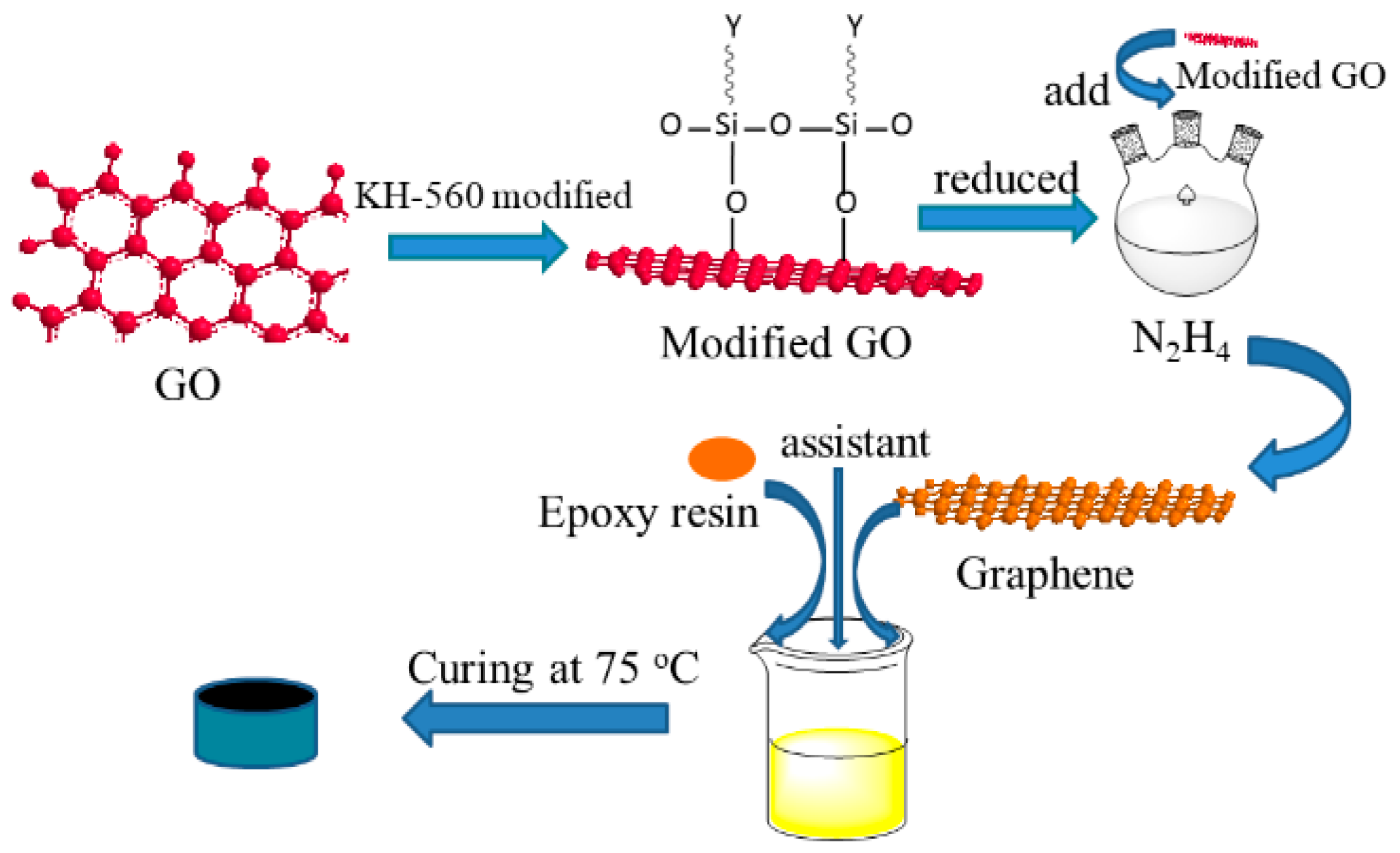
2.2. Preparation of Modified GO
2.3. Reduction of Modified GO
2.4. Preparation of Modified GE/EP Composites
2.5. Characterization
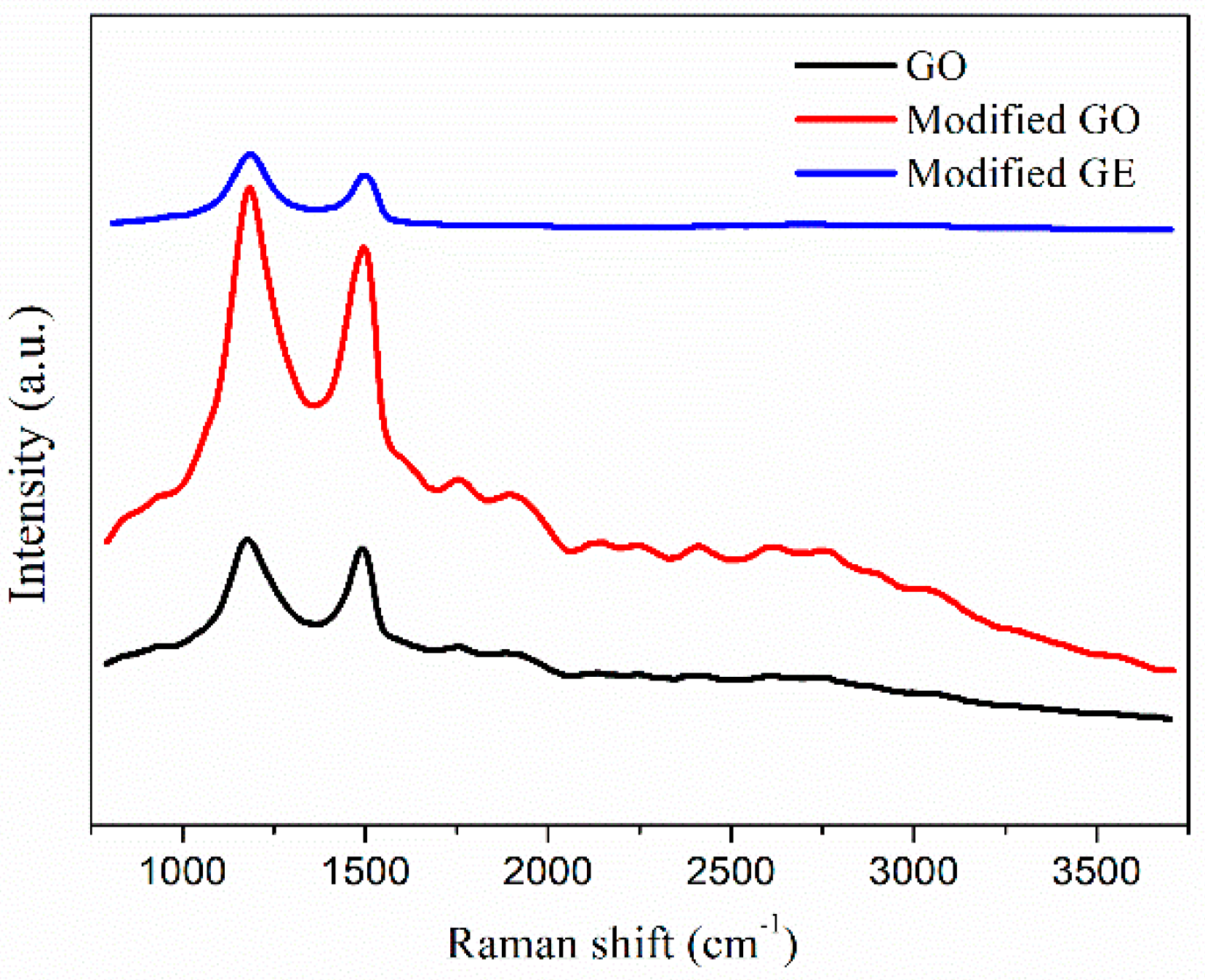
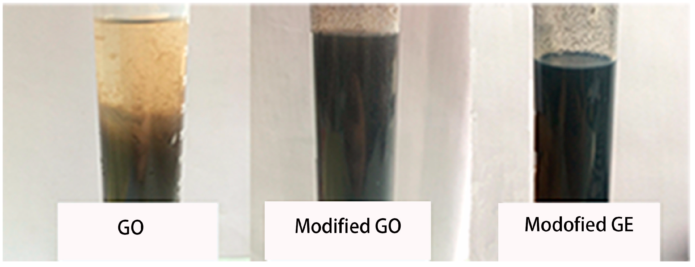
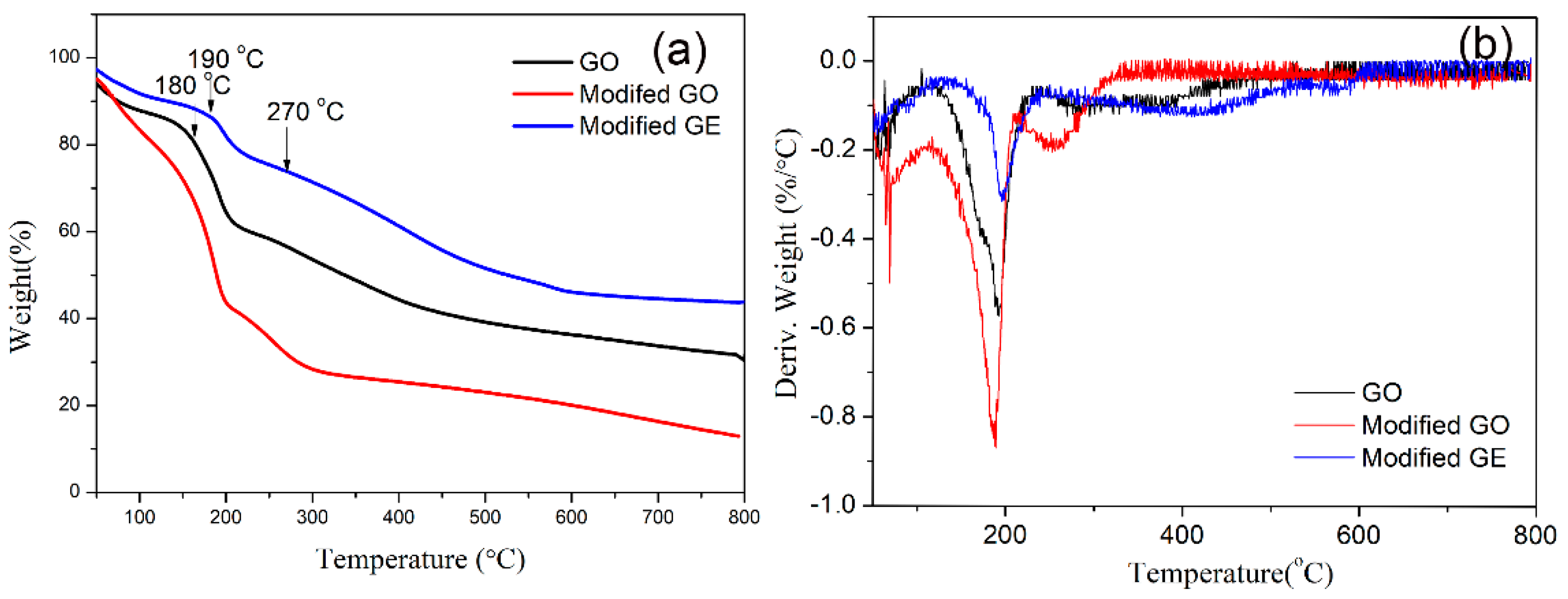
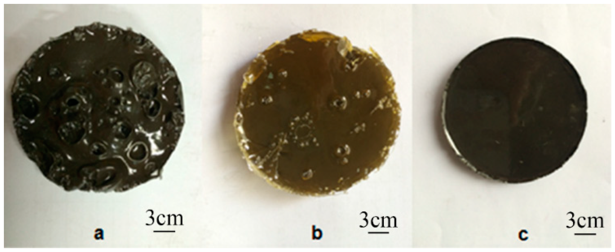
3. Results and Discussions
4. Conclusions
Author Contributions
Funding
Acknowledgments
Conflicts of Interest
References
- Sumfleth, J.; Buschhorn, S.T.; Schulte, K. Comparison of rheological and electrical percolation phenomena in carbon black and carbon nanotube filled epoxy polymers. J. Mater. Sci. 2011, 46, 659–669. [Google Scholar] [CrossRef]
- Mazov, I.; Burmistrov, I.; Il’inykh, I.; Stepashkin, A.; Kuznetsov, D.; Issi, J.P. Anisotropic thermal conductivity of polypropylene composites filled with carbon fibers and multiwall carbon nanotubes. Polym. Compos. 2015, 36, 1951–1957. [Google Scholar] [CrossRef]
- Manta, A.; Gresil, M.; Soutis, C. Predictive model of graphene based polymer nanocomposites: Electrical performance. Appl. Compos. Mater. 2017, 24, 281–300. [Google Scholar] [CrossRef]
- Pan, Y.; Sahoo, N.G.; Li, L. The application of graphene oxide in drug delivery. Expert Opin. Drug Deliv. 2012, 9, 1365–1376. [Google Scholar] [CrossRef] [PubMed]
- Service, R.F. Materials science. Carbon sheets an atom thick give rise to graphene dreams. Science 2009, 324, 875–877. [Google Scholar] [CrossRef] [PubMed]
- Balandin, A.A.; Ghosh, S.; Bao, W.; Calizo, I.; Teweldebrhan, D.; Miao, F.; Lau, C.N. Superior thermal conductivity of single-layer graphene. Nano Lett. 2008, 8, 902–907. [Google Scholar] [CrossRef] [PubMed]
- Heersche, H.B.; Jarillo-Herrero, P.; Oostinga, J.B.; Vandersypen, L.M.; Morpurgo, A.F. Bipolar supercurrent in graphene. Nature 2007, 446, 56–59. [Google Scholar] [CrossRef] [PubMed] [Green Version]
- Pullicino, E.; Zou, W.; Gresil, M.; Soutis, C. The effect of shear mixing speed and time on the mechanical properties of GNP/epoxy composites. Appl. Compos. Mater. 2017, 24, 301–311. [Google Scholar] [CrossRef]
- Zhao, Y.H.; Wu, Z.K.; Bai, S.L. Study on thermal properties of graphene foam/graphene sheets filled polymer composites. Compos. Part A Appl. Sci. Manuf. 2015, 72, 200–206. [Google Scholar] [CrossRef]
- Zhao, P.; Luo, Y.; Yang, J.; He, D.; Kong, L.; Zheng, P.; Yang, Q. Electrically conductive graphene-filled polymer composites with well organized three-dimensional microstructure. Mater. Lett. 2014, 121, 74–77. [Google Scholar] [CrossRef]
- Zhao, Y.H.; Zhang, Y.F.; Bai, S.L.; Yuan, X.W. Carbon fibre/graphene foam/polymer composites with enhanced mechanical and thermal properties. Compos. Part B Eng. 2016, 94, 102–108. [Google Scholar] [CrossRef]
- Kim, H.; Miura, Y.; Macosko, C.W. Graphene/polyurethane nanocomposites for improved gas barrier and electrical conductivity. Chem. Mater. 2010, 22, 3441–3450. [Google Scholar] [CrossRef]
- Bai, H.; Li, C.; Shi, G. Functional composite materials based on chemically converted graphene. Adv. Mater. 2011, 23, 1089–1115. [Google Scholar] [CrossRef] [PubMed]
- Guo, Z.; Song, L.; Boay, C.G.; Li, Z.; Li, Y.; Wang, Z. A new multiscale numerical characterization of mechanical properties of graphene-reinforced polymer-matrix composites. Compos. Struct. 2018, 199, 1–9. [Google Scholar] [CrossRef]
- Chen, Y.; Li, D.; Yang, W.; Xiao, C.; Wei, M. Effects of different amine-functionalized graphene on the mechanical, thermal, and tribological properties of polyimide nanocomposites synthesized by in situ polymerization. Polymer 2018, 140, 56–72. [Google Scholar] [CrossRef]
- Alam, A.; Meng, Q.; Shi, G.; Arabi, S.; Ma, J.; Zhao, N.; Kuan, H.C. Electrically conductive, mechanically robust, pH-sensitive graphene/polymer composite hydrogels. Compos. Sci. Technol. 2016, 127, 119–126. [Google Scholar] [CrossRef]
- Govorov, A.; Wentzel, D.; Miller, S.; Kanaan, A.; Sevostianov, I. Electrical conductivity of epoxy-graphene and epoxy-carbon nanofibers composites subjected to compressive loading. Int. J. Eng. Sci. 2018, 123, 174–180. [Google Scholar] [CrossRef]
- Ji, X.; Xu, Y.; Zhang, W.; Cui, L.; Liu, J. Review of functionalization, structure and properties of graphene/polymer composite fibers. Compos. Part A Appl. Sci. Manuf. 2016, 87, 29–45. [Google Scholar] [CrossRef]
- Novoselov, K.S.; Geim, A.K.; Morozov, S.V.; Jiang, D.A.; Zhang, Y.; Dubonos, S.V.; Grigorieva, I.V.; Firsov, A.A. Electric field effect in atomically thin carbon films. Science 2004, 306, 666–669. [Google Scholar] [CrossRef] [PubMed]
- Reina, A.; Jia, X.; Ho, J.; Nezich, D.; Son, H.; Bulovic, V.; Dresselhaus, M.S.; Kong, J. Large area, few-layer graphene films on arbitrary substrates by chemical vapor deposition. Nano Lett. 2008, 9, 30–35. [Google Scholar] [CrossRef] [PubMed]
- Sutter, P.W.; Flege, J.I.; Sutter, E.A. Epitaxial graphene on ruthenium. Nat. Mater. 2008, 7, 406–411. [Google Scholar] [CrossRef] [PubMed]
- Zang, C.G.; Zhu, X.D.; Jiao, Q.J. Enhanced mechanical and electrical properties of nylon-6 composite by using carbon fiber/graphene multiscale structure as additive. J. Appl. Polym. Sci. 2015, 132, 41968. [Google Scholar] [CrossRef]
- Dai, W.; Yu, J.; Wang, Y.; Song, Y.; Bai, H.; Nishimura, K.; Liao, H.W.; Jiang, N. Enhanced thermal and mechanical properties of polyimide/graphene composites. Macromol. Res. 2014, 22, 983–989. [Google Scholar] [CrossRef]
- Zhang, Z.; Zhang, W.; Li, D.; Sun, Y.; Wang, Z.; Hou, C.; Chen, L.; Cao, Y.; Liu, Y. Mechanical and anticorrosive properties of graphene/epoxy resin composites coating prepared by in-situ method. Int. J. Mol. Sci. 2015, 16, 2239–2251. [Google Scholar] [CrossRef] [PubMed]
- Lotya, M.; King, P.J.; Khan, U.; De, S.; Coleman, J.N. High-concentration, surfactant-stabilized graphene dispersions. ACS Nano 2010, 4, 3155–3162. [Google Scholar] [CrossRef] [PubMed]
- Wei, D.; Li, H.; Han, D.; Zhang, Q.; Niu, L.; Yang, H.; Bower, C.; Andrew, P.; Ryhänen, T. Properties of graphene inks stabilized by different functional groups. Nanotechnology 2011, 22, 245702. [Google Scholar] [CrossRef] [PubMed]
- Lee, C.L.; Chen, C.H.; Chen, C.W. Graphene nanosheets as ink particles for inkjet printing on flexible board. Chem. Eng. J. 2013, 230, 296–302. [Google Scholar] [CrossRef]
- Shulga, Y.M.; Bskakoy, S.A.; Baskakova, Y.V.; Lobach, A.S.; Kabachkov, E.N.; Volfkpvich, Y.M.; Sosenkin, V.E.; Shulga, N.Y.; Nefedkin, S.I.; Kumar, Y.; et al. Preparation of graphene oxide-humic acid composite-based ink for printing thin film electrodes for micro-supercapacitors. J. Alloys Compd. 2018, 730, 88–95. [Google Scholar] [CrossRef]
- Nemala, S.S.; Kartikay, P.; Agrawal, R.K.; Bhargava, P.; Mallick, S.; Bohm, S. Few layers graphene based conductive composite inks for Pt free stainless steel counter electrodes for DSSC. Sol. Energy 2018, 169, 67–74. [Google Scholar] [CrossRef]
- Fang, H.; Zhou, T.; Chen, X.; Li, S.; Shen, G.; Liao, X. Controlled preparation and characterization of nano-sized hexagonal Mg(OH)2 flame retardant. Particuology 2014, 14, 51–56. [Google Scholar] [CrossRef]
- Hummers, W.S., Jr.; Offeman, R.E. Preparation of graphitic oxide. J. Am. Chem. Soc. 1958, 80, 1339. [Google Scholar] [CrossRef]
- Petersen, M.R.; Chen, A.; Roll, M.; Jung, S.J.; Yossef, M. Mechanical properties of fire-retardant glass fiber-reinforced polymer materials with alumina tri-hydrate filler. Compos. Part B Eng. 2015, 78, 109–121. [Google Scholar] [CrossRef] [Green Version]
- Zhu, J.; Liu, A.; Wang, D. Study on the synergistic lithium storage performance of Sn/graphene nanocomposites via quantum chemical calculations and experiments. Appl. Surf. Sci. 2017, 416, 751–756. [Google Scholar] [CrossRef]
- Mahesha, G.T.; Shenoy, S.B.; Kini, V.M.; Padmarajia, N.H. Effect of fiber treatments on mechanical properties of Grewia serrulata bast fiber reinforced polyester composites. Mater. Today Proc. 2018, 5, 138–144. [Google Scholar] [CrossRef]
- Tessonnier, J.P.; Barteau, M.A. Dispersion of alkyl-chain-functionalized reduced graphene oxide sheets in nonpolar solvents. Langmuir 2012, 28, 6691–6697. [Google Scholar] [CrossRef] [PubMed]
- Noh, Y.J.; Kim, S.Y. Synergistic improvement of thermal conductivity in polymer composites filled with pitch based carbon fiber and graphene nanoplatelets. Polym. Test. 2015, 45, 132–138. [Google Scholar] [CrossRef]
- Mannaϊ, A.; Saidi, S.; Gmati, F.; Mohamed, A.B. Effects of hydrogen peroxide on the electrical conductivity of graphite/polyaniline composites. Mater. Sci. Semicond. Process. 2016, 41, 350–357. [Google Scholar] [CrossRef]
- Markervich, E.; Salitra, G.; Levi, M.D.; Aurbach, D. Capacity fading of lithiated graphite electrodes studied by a combination of electroanalytical methods, Raman spectroscopy and SEM. J. Power Sources 2005, 146, 146–150. [Google Scholar] [CrossRef]
- Chen, L.; Li, N.; Zhang, M.; Li, P.; Lin, Z. Effect of preparation methods on dispersion stability and electrochemical performance of graphene sheets. J. Solid State Chem. 2017, 249, 9–14. [Google Scholar] [CrossRef]
- Stankovich, S.; Dikin, D.A.; Piner, R.D.; Kohlhaas, K.A.; Kleinhammes, A.; Jia, Y.; Wu, Y.; Nguyen, S.T.; Ruoff, R.S. Synthesis of graphene-based nanosheets via chemical reduction of exfoliated graphite oxide. Carbon 2007, 45, 1558–1565. [Google Scholar] [CrossRef]
- Qin, H.; Zhang, S.; Zhao, C.; Feng, M.; Yang, M.; Shu, Z.; Yang, S. Thermal stability and flammability of polypropylene/montmorillonite composites. Polym. Degrad. Stab. 2004, 85, 807–813. [Google Scholar] [CrossRef]
- Qiu, F.; Hao, Y.; Li, X.; Wang, B.; Wang, M. Functionalized graphene sheets filled isotactic polypropylene nanocomposites. Compos. Part B Eng. 2015, 71, 175–183. [Google Scholar] [CrossRef]
- Tang, L.C.; Wan, Y.J.; Yan, D.; Pei, Y.B.; Zhao, L.; Li, Y.; Wu, L.B.; Jiang, J.X.; Lai, G.Q. The effect of graphene dispersion on the mechanical properties of graphene/epoxy composites. Carbon 2013, 60, 16–27. [Google Scholar] [CrossRef]
- Chhetri, S.; Adak, N.C.; Samanta, P.; Murmu, N.C.; Kuila, T. Functionalized reduced graphene oxide/epoxy composites with enhanced mechanical properties and thermal stability. Polym. Test. 2017, 63, 1–11. [Google Scholar] [CrossRef]
- Radzuan, N.A.M.; Zakaria, M.Y.; Sulong, A.B.; Sahari, J. The effect of milled carbon fibre filler on electrical conductivity in highly conductive polymer composites. Compos. Part B Eng. 2017, 110, 153–160. [Google Scholar] [CrossRef]
- Xu, H.; Gong, L.X.; Wang, X.; Zhao, L.; Pei, Y.B.; Wang, G.; Liu, Y.J.; Wu, L.B.; Jiang, J.X.; Tang, L.C. Influence of processing conditions on dispersion, electrical and mechanical properties of graphene-filled-silicone rubber composites. Compos. Part A Sci. Manuf. 2016, 91, 53–64. [Google Scholar] [CrossRef]
- Bauhofer, W.; Kovacs, J.Z. A review and analysis of electrical percolation in carbon nanotube polymer composites. Compos. Sci. Technol. 2009, 69, 1486–1498. [Google Scholar] [CrossRef] [Green Version]
- Noël, A.; Faucheu, J.; Rieu, M.; Viricelle, J.P.; Bourgeat-Lami, E. Tunable architecture for flexible and highly conductive graphene–polymer composites. Compos. Sci. Technol. 2014, 95, 82–88. [Google Scholar] [CrossRef] [Green Version]
- Zhao, S.; Chang, H.; Chen, S.; Cui, J.; Yan, Y. High-performance and multifunctional epoxy composites filled with epoxide-functionalized grapheme. Eur. Polym. J. 2016, 84, 300–312. [Google Scholar] [CrossRef]
- Wang, K.; Wang, W.; Wang, H.; Liu, L.; Xu, Z.; Fu, H.; Zhao, L.; Zhang, X.; Chen, L.; Zhao, Y. 3D graphene foams/epoxy composites with double-sided binder polyaniline interlayers for maintaining excellent electrical conductivities and mechanical properties. Compos. Part A Appl. Sci. Manuf. 2018, 110, 246–257. [Google Scholar] [CrossRef]
- Xu, X.Z.; Lin, G.M.; Liu, D.Y.; Sui, G.X.; Yang, R. Electrically conductive graphene-coated polyurethane foam and its epoxy composites. Compos. Commun. 2018, 7, 1–6. [Google Scholar]
- Ma, P.C.; Tang, B.Z.; Kim, J.K. Effect of CNT decoration with silver nanoparticles on electrical conductivity of CNT-polymer composites. Carbon 2008, 46, 1497–1505. [Google Scholar] [CrossRef]
- Jia, J.; Sun, X.; Lin, X.; Shen, X.; Mai, Y.W.; Kim, J.K. Exceptional electrical conductivity and fracture resistance of 3D interconnected graphene foam/epoxy composites. ACS Nano 2014, 8, 5774–5783. [Google Scholar] [CrossRef] [PubMed]
- Wang, P.; Chong, H.; Zhang, J.; Lu, H. Constructing 3D graphene networks in polymer composites for significantly improved electrical and mechanical properties. ACS Appl. Mater. Interfaces 2017, 9, 22006–22017. [Google Scholar] [CrossRef] [PubMed]
- Chiang, T.H.; Liu, C.Y.; Lin, Y.C. The effect of an anhydride curing agent, an accelerant, and non-ionic surfactants on the electrical resistivity of graphene/epoxy composites. J. Appl. Polym. Sci. 2015, 132, 41975. [Google Scholar] [CrossRef]


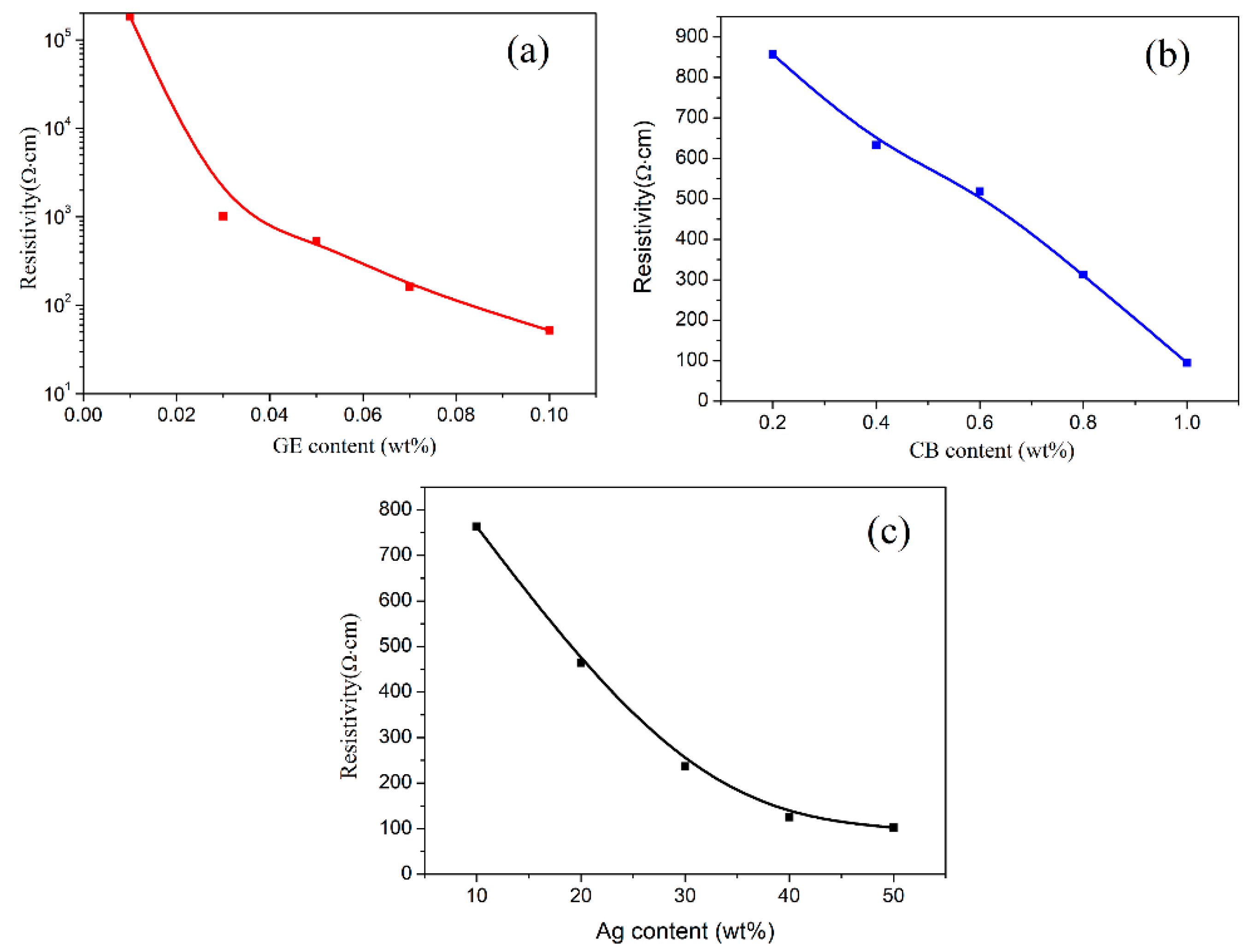
| Filler | Samples | Resistivity (Ω·cm) |
|---|---|---|
| Modified GE | Modified GE/EP-0.01 | 1.84 × 10⁵ |
| Modified GE/EP-0.03 | 1013 | |
| Modified GE/EP-0.05 | 534 | |
| Modified GE/EP-0.07 | 162 | |
| Modified GE/EP-0.1 | 52 | |
| CB | CB/EP-0.2 | 857 |
| CB/EP-0.4 | 633 | |
| CB/EP-0.6 | 518 | |
| CB/EP-0.8 | 313 | |
| CB/EP-1 | 95 | |
| Ag particles | Ag/EP-10 | 763 |
| Ag/EP-20 | 464 | |
| Ag/EP-30 | 237 | |
| Ag/EP-40 | 125 | |
| Ag/EP-50 | 102 |
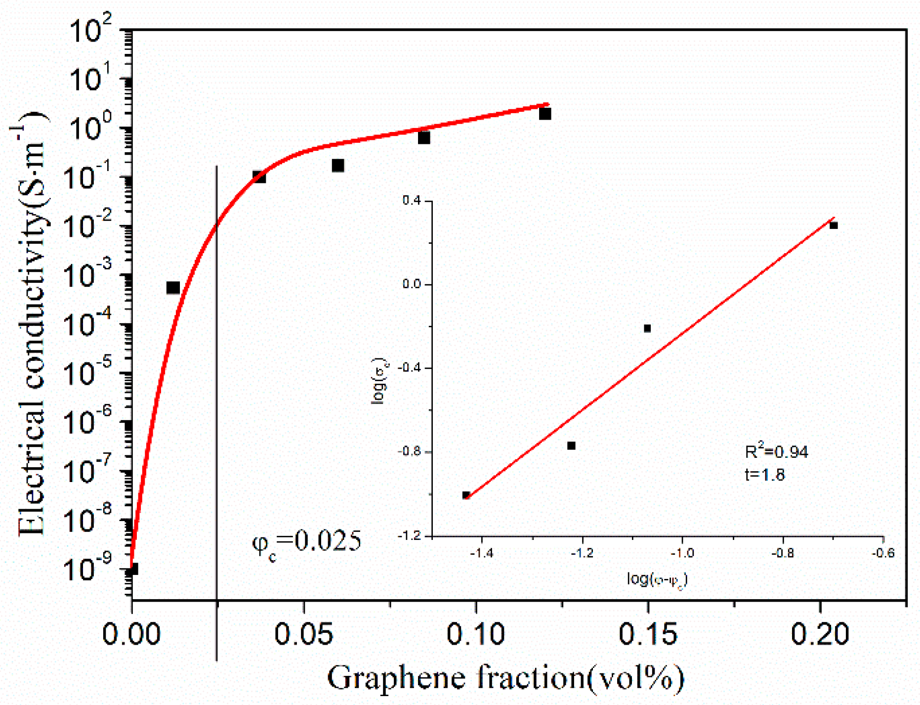
| Volume Fraction (vol %) | Conductivity (S·m−1) |
|---|---|
| 0.012 | 5.4 × 10⁻⁴ |
| 0.037 | 0.099 |
| 0.06 | 0.17 |
| 0.085 | 0.62 |
| 0.12 | 1.92 |
| Filler | Polymer Matrix | Content | Conductivity (S·m−1) |
|---|---|---|---|
| GE [10] | Polystyrene | 0.81 vol % | 15.7 |
| Epoxide-functionalized GE [49] | Epoxy | 0.48 vol % | 7.8 × 10⁻⁸ |
| 3D GE foam-PANI [50] | Epoxy | 0.39 wt % | 0.134 |
| GE-coated PU foam [51] | Epoxy | 0.9 wt % | 2.46 |
| Ag@CNTs [52] | Epoxy | 0.5 wt % | 0.8 |
| GE foam [53] | Epoxy | 0.2 wt % | 3 |
| GE [54] | Polyamide | 2.45 vol % | 60 |
| GE [55] | Epoxy | 13 wt % | 8.56 |
© 2018 by the authors. Licensee MDPI, Basel, Switzerland. This article is an open access article distributed under the terms and conditions of the Creative Commons Attribution (CC BY) license (http://creativecommons.org/licenses/by/4.0/).
Share and Cite
Cheng, Y.; Zhang, Q.; Fang, C.; Chen, J.; Su, J.; Xu, K.; Ai, L.; Liu, D. Preparation, Structure, and Properties of Surface Modified Graphene/Epoxy Resin Composites for Potential Application in Conductive Ink. Coatings 2018, 8, 387. https://doi.org/10.3390/coatings8110387
Cheng Y, Zhang Q, Fang C, Chen J, Su J, Xu K, Ai L, Liu D. Preparation, Structure, and Properties of Surface Modified Graphene/Epoxy Resin Composites for Potential Application in Conductive Ink. Coatings. 2018; 8(11):387. https://doi.org/10.3390/coatings8110387
Chicago/Turabian StyleCheng, Youliang, Qingling Zhang, Changqing Fang, Jing Chen, Jian Su, Kaiyan Xu, Liangliang Ai, and Donghong Liu. 2018. "Preparation, Structure, and Properties of Surface Modified Graphene/Epoxy Resin Composites for Potential Application in Conductive Ink" Coatings 8, no. 11: 387. https://doi.org/10.3390/coatings8110387