Wide-Angle Beam Scanning Leaky-Wave Antenna Using Spoof Surface Plasmon Polaritons Structure


1
College of Electronic and Optical Engineering, Nanjing University of Posts and Telecommunications, Nanjing 210003, China
2
State Key Laboratory of Millimeter Waves, Southeast University, Nanjing 210096, China
3
Electrical and Computer Engineering Department, National University of Singapore, Singapore 117583, Singapore
*
Author to whom correspondence should be addressed.
Electronics 2018, 7(12), 348; https://doi.org/10.3390/electronics7120348
Submission received: 21 October 2018
/
Revised: 16 November 2018
/
Accepted: 19 November 2018
/
Published: 24 November 2018
(This article belongs to the Section Microwave and Wireless Communications)
Abstract
:This paper proposes a wide-angle beam scanning leaky-wave antenna (LWA) fed by a novel spoof surface plasmon polaritons (SSPP) transmission line (TL). In the proposed LWA, circular metallic patches are periodically loaded on both sides of the SSPP TL alternately, and convert guided waves into radiating waves. The transmission characteristics of the proposed SSPP TL are analyzed, and the transmission characteristics and radiation patterns of the proposed LWA are simulated and measured. The simulated and measured results show that the proposed LWA provides approximately 12.5 dBi of radiation gain within a frequency range of 8–24 GHz, and a beam scanning range of 90° from forward to backward continuously by increasing the feeding frequency. The proposed LWA, based on a novel SSPP TL, has advantages of single-layer conductor, continuous wide-angle beam scanning, and high gain especially at the broadside direction, which are difficult realize using conventional LWAs.
1. Introduction
Leaky-wave antennas (LWAs) have attracted significant attention in microwave engineering due to their advantages of simple feeding network, frequency beam scanning, high directivity and low cost [1]. Because a fast wave transmission line (TL) can feed a LWA to radiate, the initial design of LWAs are based on the waveguides supporting fast wave modes, such as slotted rectangular waveguides [2] and substrate integrated waveguides [3]. Many periodic structures operating on space harmonic waves are explored to feed LWAs, such as microstrip lines, groove waveguides and metamaterials structures [4,5,6]. With the rapid development of integrated circuits, planar antennas with single-layer conductors are explored. The spoof surface plasmon polaritons (SSPP) TL is a single-conductor line without ground plane. Since it confines the electromagnetic wave strongly around the interface between the metal and dielectric, the SSPP TL performs well in the integrated planar circuit system [7].
Surface plasmon polaritons are surface electromagnetic waves distributed at the interface of a dielectric and a conductor, which could only be excited at visible frequencies. In 2004, Pendry and his colleagues proposed a new structure that could excite surface plasmon polariton waves at lower frequencies [8]. On the basis of Pendry’s work, Garcia-Vidal proposed a scheme for realizing artificial surface plasmon with a one-dimensional periodic perforation structure [9]. The ultra-thin SSPP TL can be realized by processing the samples on flexible material films with PCB technology [10]. Early SSPP were mainly excited by probes or radiation sources, and the efficiency was not high [11,12,13]. In Reference [14], Ma used a coplanar waveguide to excite a periodically grooved metal strip with a high efficiency. Since then, varieties of TL structures based on SSPP have been proposed and widely used in designs of antennas and filters [7,15,16,17,18,19,20]. In Reference [16], the SSPP TL was used as a feeding configuration for a dielectric resonator antenna. As they are high confinement and low profile, SSPP TLs are especially suitable for designing the leaky-wave antenna [20,21,22]. However, the high confinements also bring difficulties in converting the SPP mode wave into the space radiating mode. To radiate leaky waves into free space, an asymmetrical SSPP waveguide is periodically modulated to achieve a continuously beam scanning LWA [20]. Since patches are good radiators, a LWA using patch array fed by an SSPP waveguide was proposed [21]. However, the scanning angle and radiation gain is not as good as traditional LWAs. In Reference [22] a patch loaded SSPP LWA with an artificial magnetic conductor ground plane was introduced to improve performances, and it turned a single-layer conductor structure into a complex 3D structure, which lost the advantage of SSPP.
In this article, we propose a wide-angle beam scanning LWA fed by a novel SSPP TL which is grooved by rectangular slots in a metallic strip. Since the SSPP structure has first been presented to feed LWA, the characteristics of this TL are discussed. Due to the advantages of the proposed SSPP, the antenna is fabricated on a single layer conductor which is easy to be integrated and conformed. The proposed LWA loaded with circular patches scans in a wide-angle range of 90 degrees continuously from forward to backward within a frequency range of 8–24 GHz, and achieves a measured average radiation gain of 12.5 dBi with a high radiation efficiency.
2. SSPP Transmission Line Design
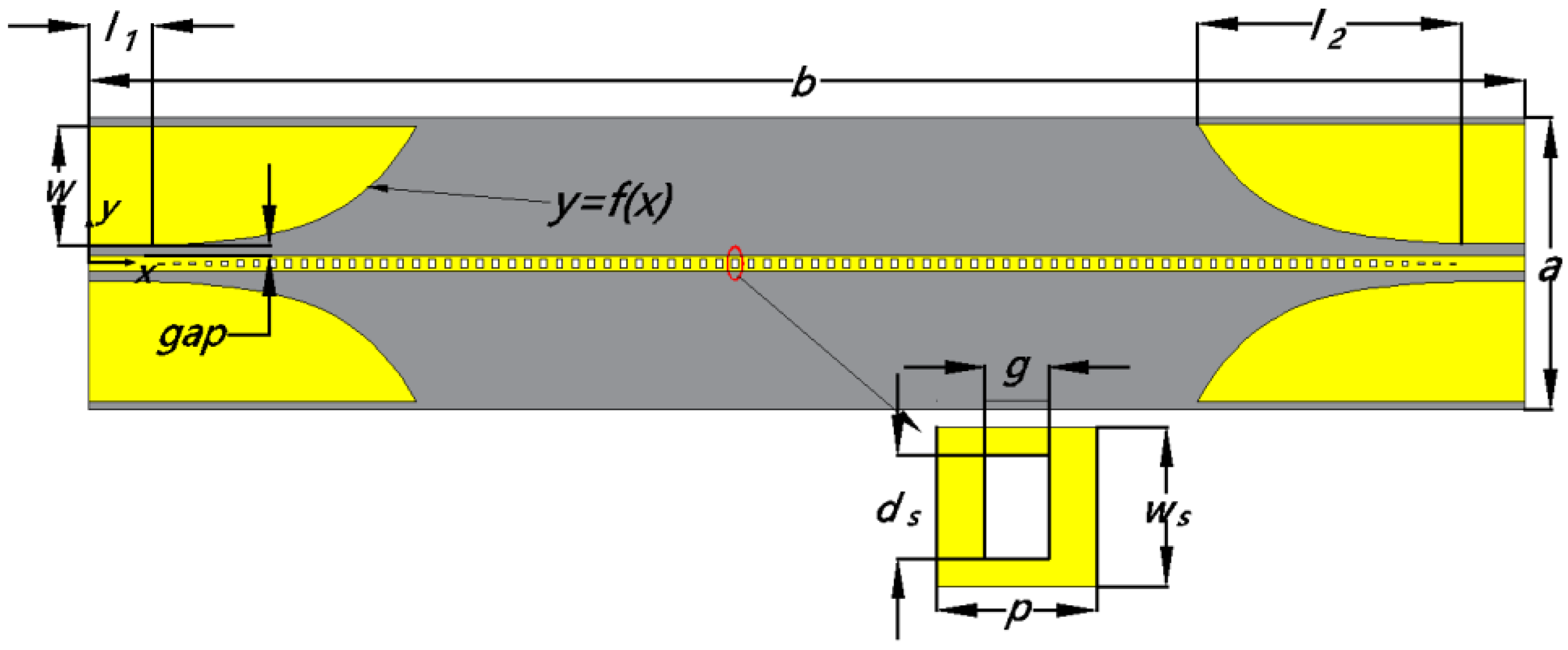
The proposed SSPP TL, shown in Figure 1, is composed of a metal strip with periodic drilled square grooves and fabricated on a single layer FR4 substrate (with εr = 4.3, tanσ = 0.025 and 0.5 mm thickness). In order to integrate such an SSPP TL with traditional microwave circuits, the matching transitions between the SSPP TL and co-planar waveguide (CPW) structures are adopted. Since the SSPP TL supports SPP mode and the CPW works on a quasi-TEM mode, a gradual transition part is designed into CPW to make smooth conversions, and the two side ground planes of CPW gradually flare to achieve a wave-vector matching. Rectangular grooves are also gradually smaller at two ports of the SSPP TL to created a better impedance matching. The CPW is designed of 50 Ω to connect the conventional Sub-miniature A (SMA) connectors. The width of the SSPP TL is a = 70 mm, in order to have a good matching, and the length of the SSPP TL is b = 404 mm which is related to the main beam width of the associated LWA. The width of grooves is g = 1.6 mm, the depth of grooves is ds = 2 mm, the length of a unit cell is p = 4 mm, and width of strip is ws = 4 mm. These parameters determine the shape of dispersion curve of the SSPP TL, and, in turn, determine the ranges of the scanning angles and frequencies.
The strip width, gap size, and length of the CPW TL close to the ports were chosen as w = 30 mm, gap = 0.5 mm, and l1 = 16 mm, respectively. The length of the transition region was set to be l2 = 66 mm based on a tradeoff between a good matching and a small size of the proposed LWA. The origin of the coordinate was set at the center of the CPW port. To convert the quasi-TEM to a SSPP wave with a high efficiency in broadband, the flaring ground was designed as an exponential curve as follows [14]:
where
θ is a coefficient to move the beginning of the curve to the coordinate origin. The design can give the structure good matching properties in a wide frequency band by matching the momentum of the conventional CPW mode into a SSPP waveguide mode.
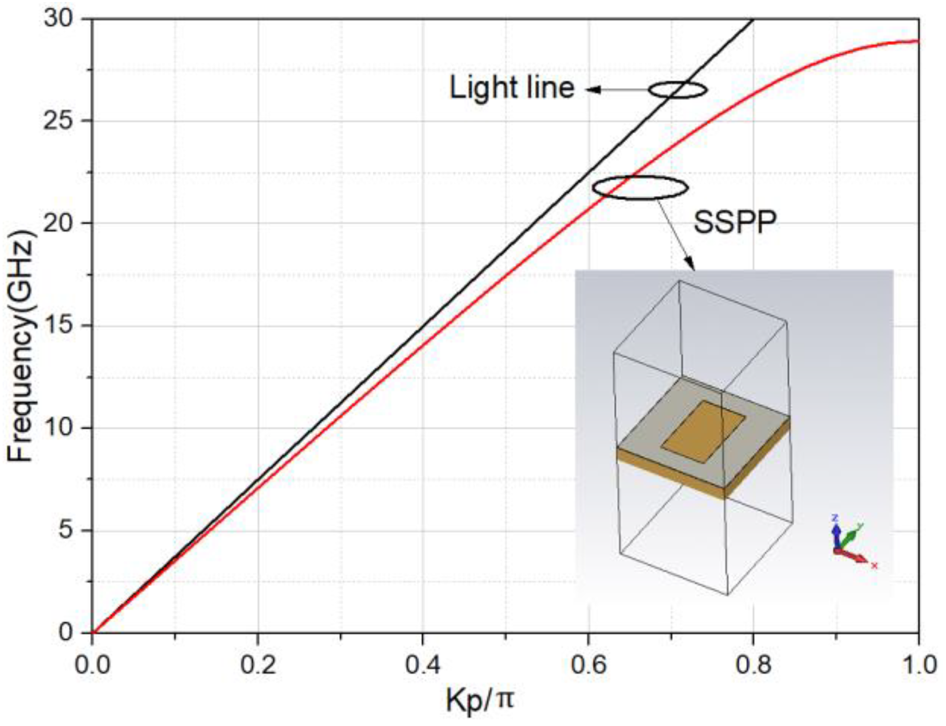
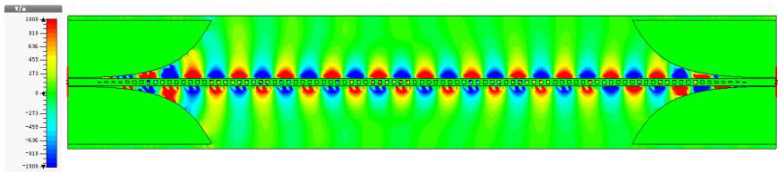
Although an SSPP TL does not have a ground plane, it can also bound electromagnetic waves, as we know. Figure 2 shows the dispersion characteristic of the proposed SSPP TL which is simulated with the Eigen-mode solver of CST Microwave Studio. The dispersion curve of the SSPP TL is always below the light’s dispersion line in its working band because an SSPP wave is a slow-wave (), and there is no radiation mode under the cutoff frequency. Figure 3 displays the simulated y-direction E-field distribution on the substrate at 10 GHz, and it appears binding TM waves on the surface metal strip. From Figure 3 we can also see smooth conversions between guided waves and SSPPs. In the CPW sections, conventional guided waves are supported. Along the matching transition sections, the guided waves are gradually transformed to SSPP waves. In the TL section, the E-field distribution behaviors like a surface plasmon polaritons, which means that SSPP waves are supported.
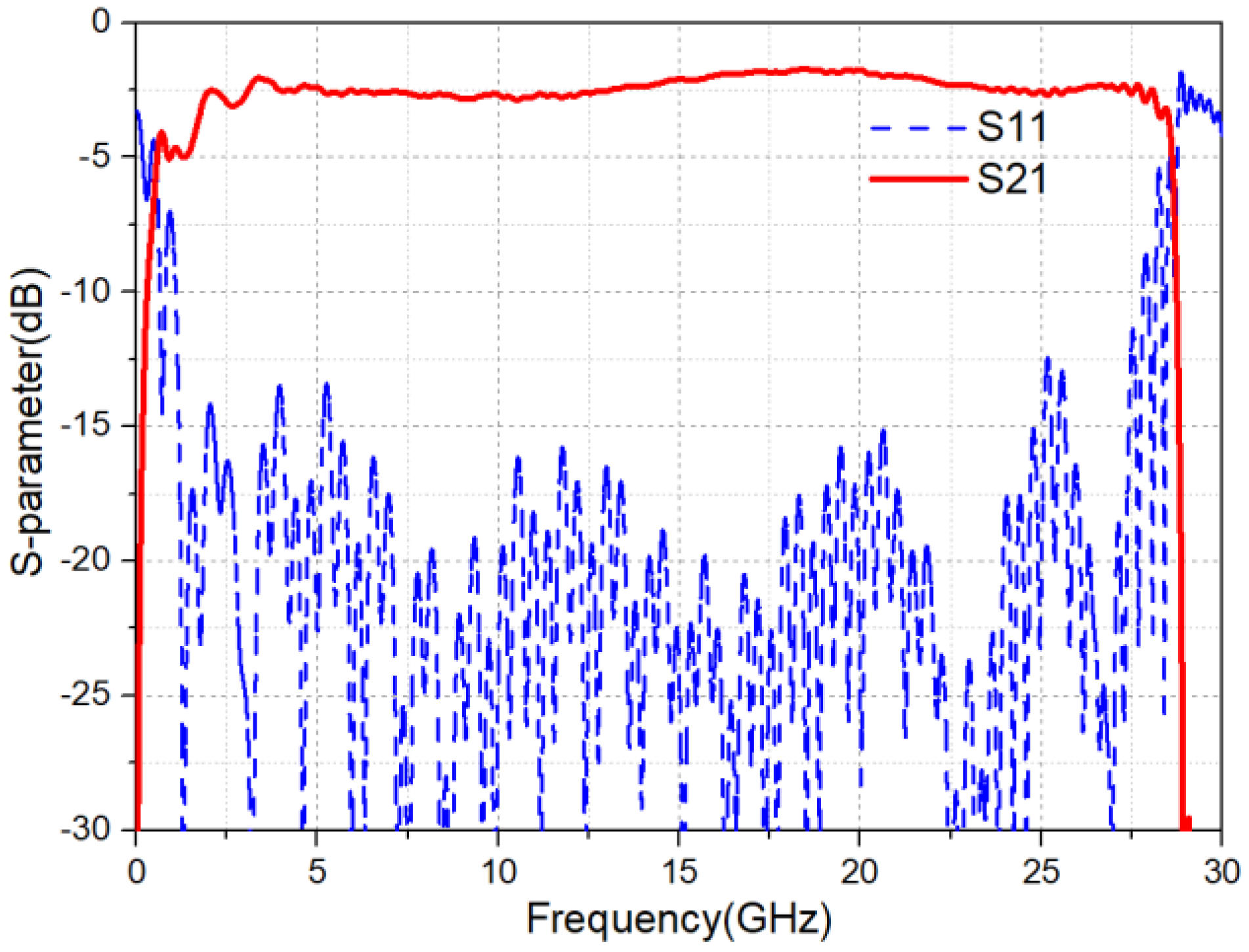
Figure 4 shows the simulated results of reflection and transmission coefficients of the proposed SSPP TL. The simulated results certify the propagation characteristics of SSPP waves, as Figure 2 indicates. Since the loss of FR4 is pretty large and the SSPP TL is long, the loss indeed affects the S-parameters. However, the transmission loss S21 is still low due to the intrinsic property of an SSPP TL [23]. To study the transmission loss performance of such a SSPP TL, numerical simulations of the SSPP TL are presented in Figure 5. In Figure 5a, we observe that the depth of grooves ds determines the cut-off frequency of the SSPP TL. As the cut-off frequency decreases, the transmission loss decreases, which leads from a stronger EM field confinements. At the same time, the width of grooves g has little effect as shown in Figure 5b. Therefore, the deeper the groove is, the lower the cut-off frequency and the stronger its confinements. To make better energy radiation, we choose to loosen the field confinements, and the geometrical parameters are chosen as Figure 1.
3. SSPP Leaky-Wave Antenna Design and Study
The SSPP TL also could serve in feeding leaky-wave antennas. In order to couple the SSPP wave to a far field radiation, circular patches were loaded on both sides of the SSPP TL.
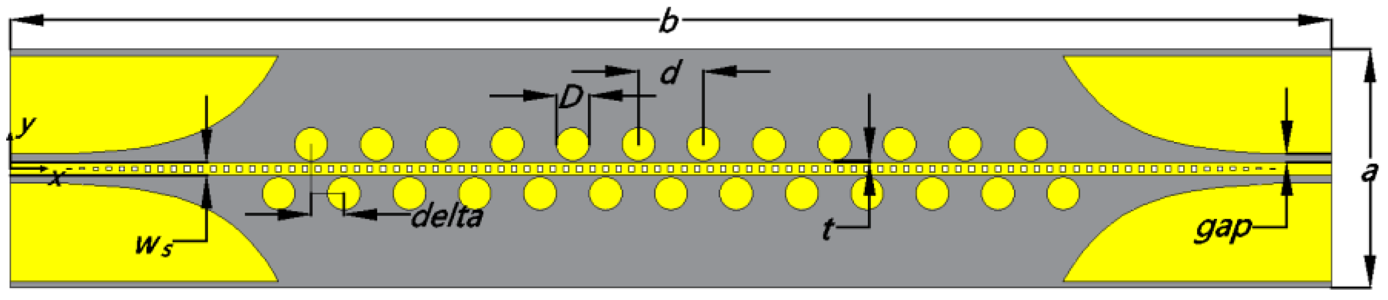
Figure 6 shows the structure of the proposed SSPP LWA fabricated on a FR4 substrate with εr = 4.3, tan σ = 0.025 and a thickness h = 0.5 mm. The SSPP TL and the substrate are the same as those shown in Figure 1. The circular patches are interlacing, placed at the two sides of the SSPP TL. The patch-loading here is used to convert surface waves into radiating space waves. The distance between the patches and the metallic strip is related to the couple which is set based on the requirement for radiation pattern. The diameter of the circle patch is D = 10 mm, which makes the radius equal to one quarter of the waveguide wavelength, approximately. The period is d = 20 mm, which is just the distance of two of the circle patches. The offset on the both sides of patches is delta = 10 mm, it equals half of the period d, which will discussed in the following. Real copper was chosen with an electrical conductivity of 5.96 × 10⁷ S/m. All the patches are t = 0.5 mm away from the TL to couple the energy from SSPP TL properly.
According to the Floquet theory, numerous spatial harmonics are ignited in the antenna, and the phases constants are:
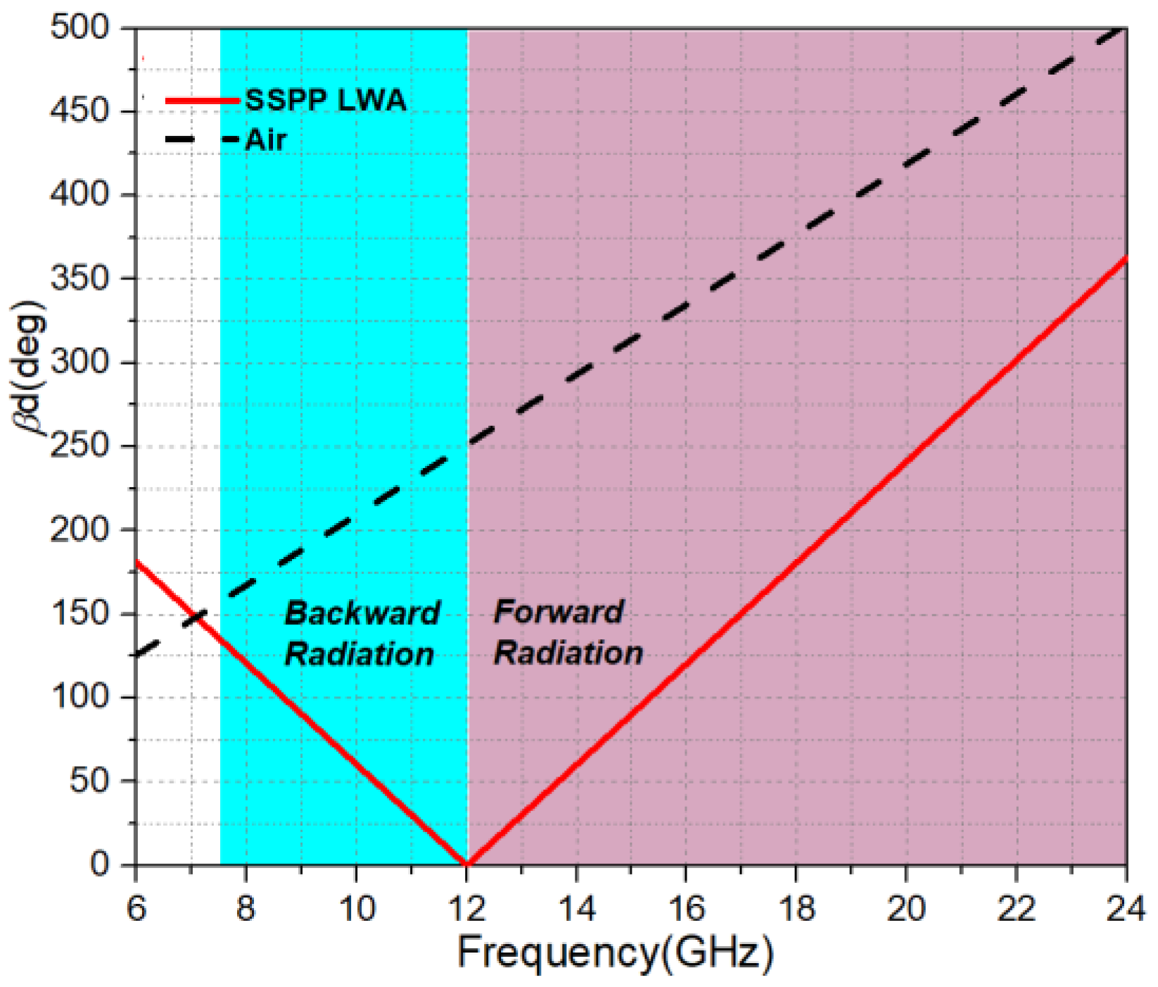
where β0 is the fundamental mode phase constant. Equation (3) shows that the space harmonics are all slow waves for n ≥ 0, meanwhile, for n < 0, the space harmonics can be fast waves. In order to get the maximum radation efficiency and obtain a single radiated beam, the n = −1 space harmonic is usually chosen to convert the transmission wave to a radiation wave. In this mode, the LWA can scan the beam in either the forward direction or the backward direction. For n = −1, we have , here k0 is the phase constant of the air line. The dispersion diagram of the proposed SSPP leaky-wave antenna is shown in Figure 7. From the relationship between phase constants of antenna and air line, we can see it works in a fast wave region from 8 GHz to 24 GHz. The frequency of broadside radiation is at 12 GHz, forward radiation is above it and backward radiation is below it.
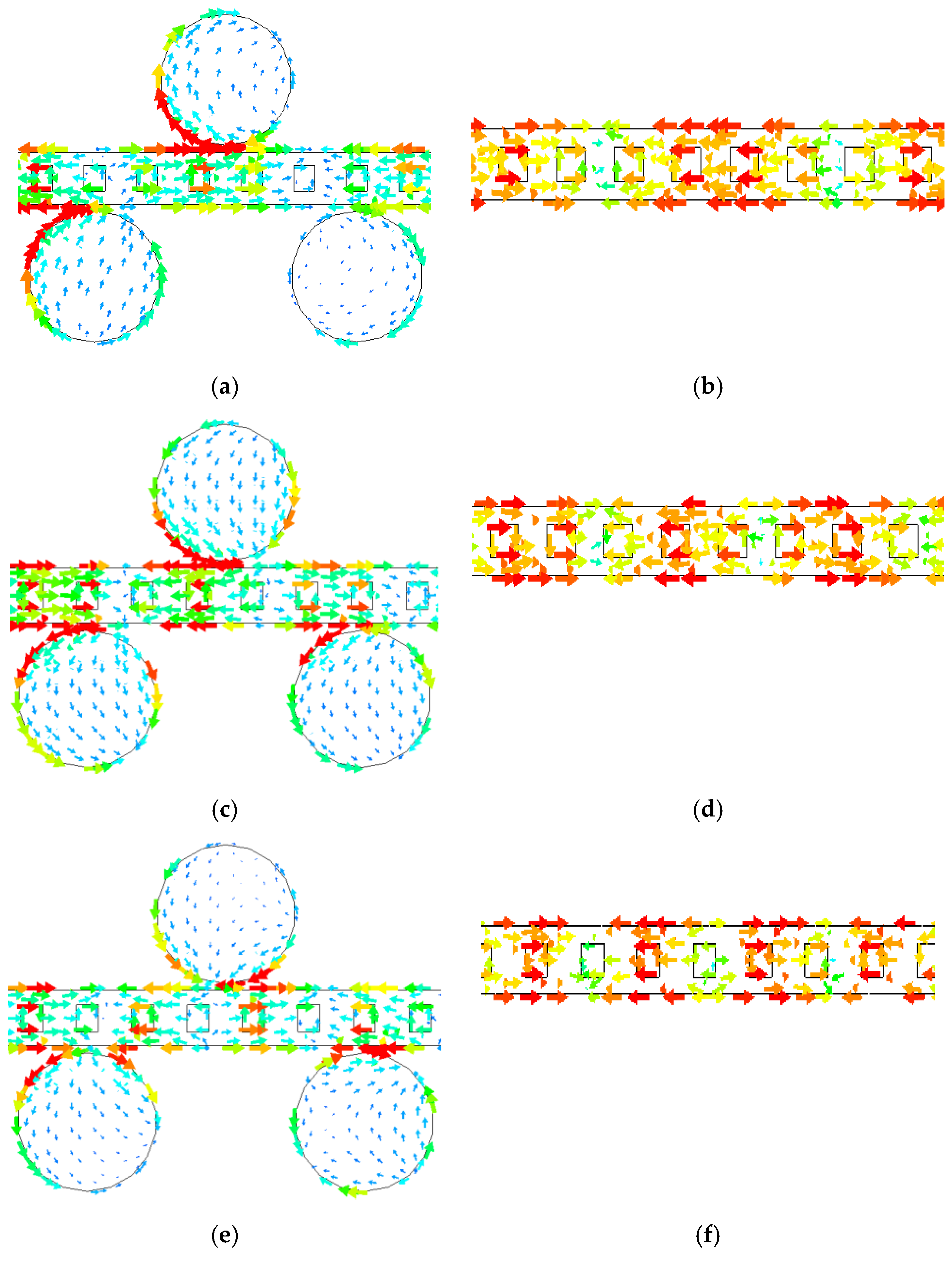
To investigate the coupling mechanism and the electromagnetic radiation, Figure 8 shows parts of the surface current distribution on both the SSPP LWA and SSPP TL at different frequencies. The simulations use a time domain solver in commercial software CST Microwave Studio. In order to achieve the maximum energy coupling, circle patches should be placed in the positions with the maximum current of the SSPP TL. However, the periods of maximum currents in phase on SSPP TLs are different at different frequencies, as shown in Figure 8b,d,f. To achieve a wide-angle beam scanning, the broadside frequency 12 GHz is to be set first. Thus, the period distance between every two of the circle patches is chosen to be d = 20 mm, which is just the period distance between every maximum current in phase at 12 GHz as shown in Figure 8c. Figure 8a displays the surface currents of SSPP LWA at 8 GHz, which brings a backward beam scanning. Figure 8f displays the surface currents of SSPP LWA at 15 GHz, which brings a forward beam scanning. From Figure 8a,c,e, we can see the surface currents couple between the TL and the patches to change smoothly, and the electromagnetic energy radiates to space in phase.
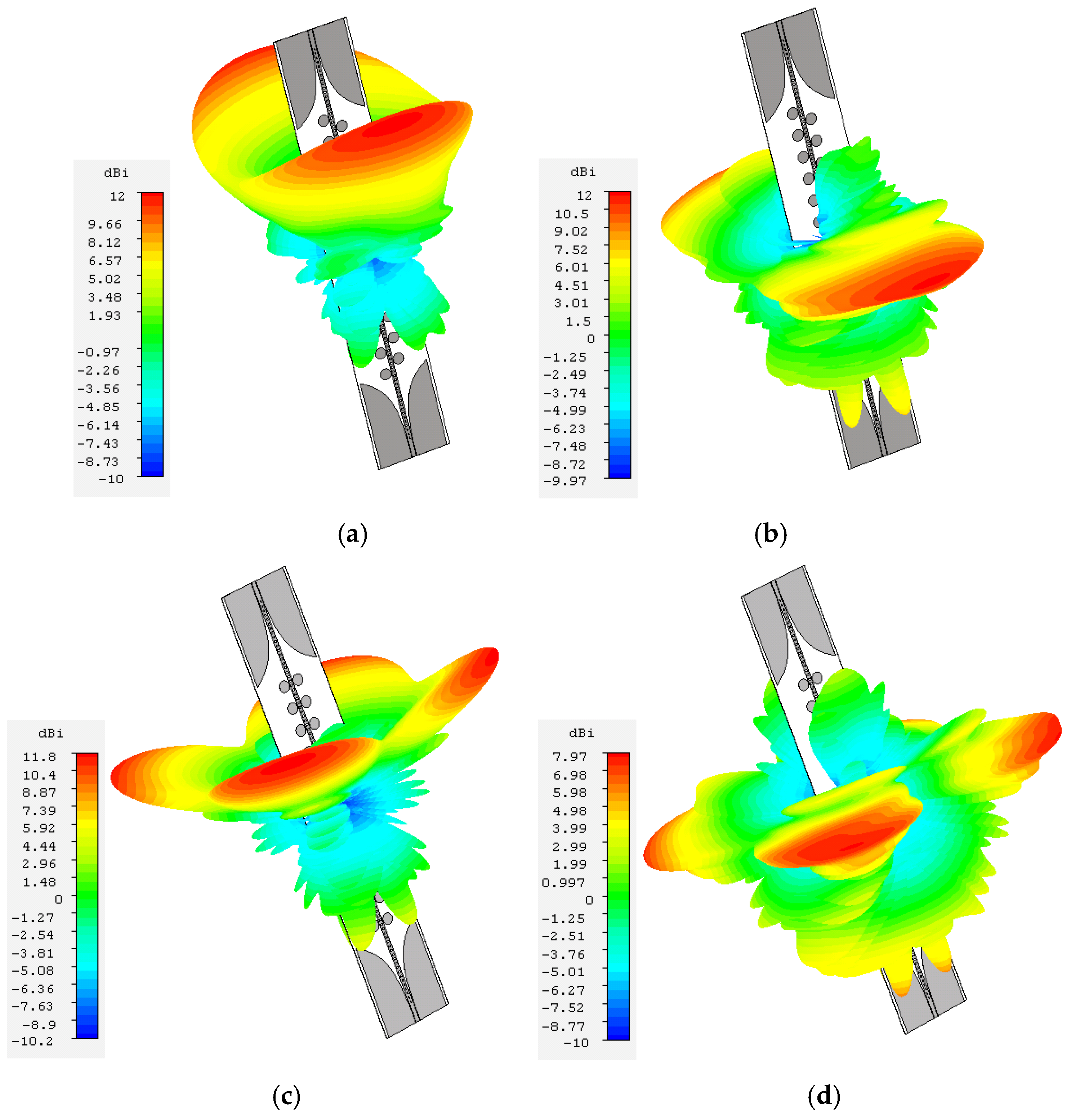
The discussion above indicates that the position of patches determines the properties of the antenna radiation. Therefore, the offset parameter delta of two sides of patches is also worth studying. Figure 9 shows the radiation patterns of the antenna under different parameters. When delta = 10 mm, the circular patches on both sides are placed alternately, and the radiation pattern has two beams owing to the no-ground SSPP TL, as shown in Figure 9a,b. When delta = 0 mm, the circular patches on both sides are placed completely symmetrically, and the radiation pattern splits into four beams owing to the symmetry inconsistent with SSPP field distribution, as shown in Figure 9c,d. Figure 9 also shows that the SSPP LWA scans backward at 8 GHz and on broadside at 12 GHz. Therefore, the simulated 3D far-field radiation patterns of the SSPP LWA are in accordance with the dispersion diagram shown in Figure 7.
4. Fabrication and Measurement
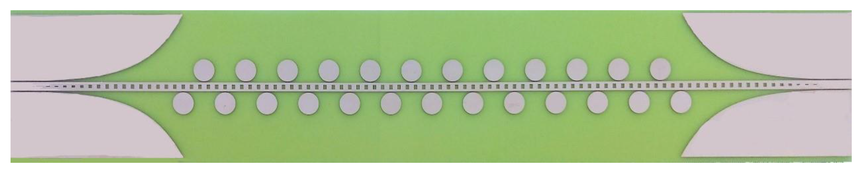
The proposed SSPP LWA was fabricated and measured to validate the design above. A photograph of the fabricated prototype is shown in Figure 10, and the sizes are shown in Figure 6. Figure 11 shows the simulated and measured reflection coefficients S11 and transmission coefficients S21 of the SSPP LWA. The reflection coefficients S11 are below −10 dB over all bandwidths. It is a little bit worse at 12 GHz because 12 GHz corresponds to the broadside direction which always creates the maximum reflection. The transmission coefficients S21 are below −22 dB over all bandwidths. Compared to a conventional LWA, the proposed SSPP LWA obtains a high radiation efficiency. The measured S21 responses do not agree well with the simulated ones at some frequencies. The difference comes from the loss of connector assembly and measurement error especially under −20 dB. However, since the S-parameters are shown in dB, the real difference is not very large under −20 dB.
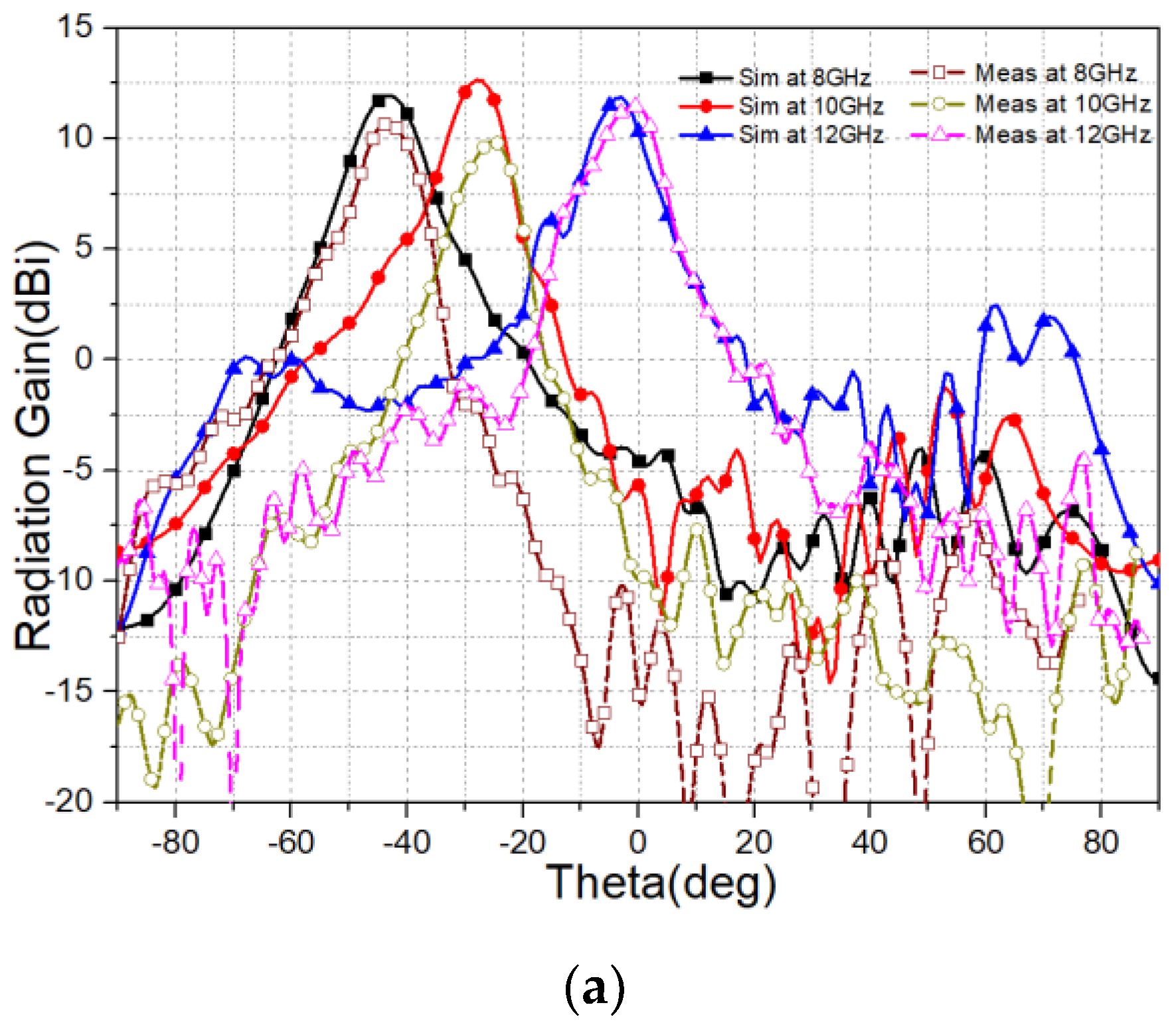
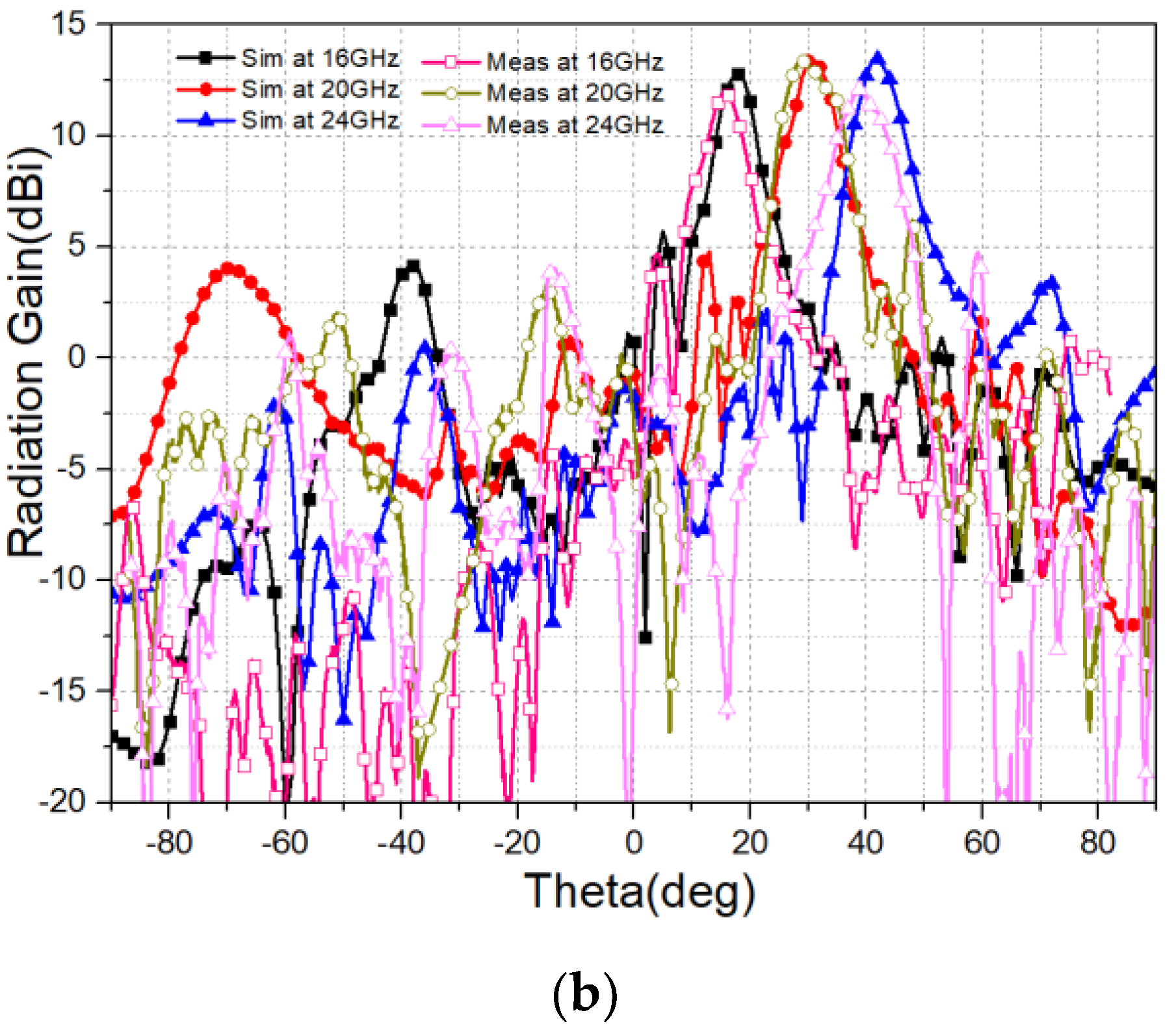
Figure 12 shows the simulated and measured radiation patterns of the proposed SSPP LWA at different frequencies. The simulated and measured results show that the proposed LWA continuously scans from −45° to 45° as the frequency increases from 8 to 24 GHz. The side lobe is lower than the main lobe by −10 dB. The backward beam scanning is shown in Figure 12a, where the broadside direction is 0° at 12 GHz, and the forward beam scanning is shown in Figure 12b. The radiation characteristics are consistent with the predictions based on the dispersion diagram in Figure 7. The proposed SSPP LWA offers a possibility of continuous beam scanning through the broadside with almost the same gain, without a drop in radiation performance at the broadside direction compared to conventional LWAs [24].
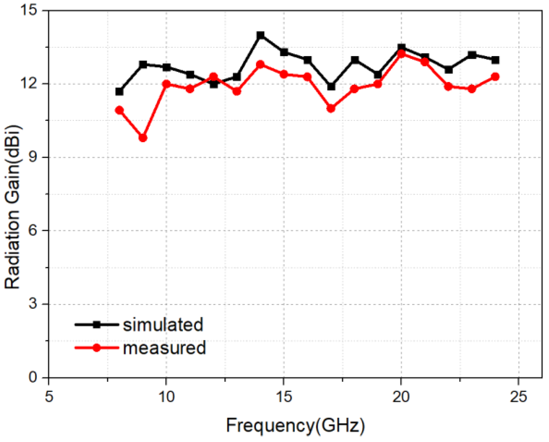
Figure 13 illustrates the radiation gains of the SSPP LWA. It is apparent that the gains can reach an average level of 12.5 dBi. Although the FR4 substrate has a relatively large dielectric loss and conductor loss, the LWA fed by the SSPP TL can still achieve a high gain due to low loss of SSPP TLs. The measured gains are consistent with the simulated ones. Compared to conventional LWAs [25], the radiation gain of the proposed SSPP LWA is relatively high and stable.
5. Conclusions
In this article, we propose a LWA for wide-angle beam scanning. The LWA consists of a novel SSPP TL with periodical rectangular grooves on the metal strip and circular patches periodically loaded on both sides of the SSPP TL. Both the simulated and measured results show that the proposed LWA exhibits a wide scanning angle range from −45° to 45° as the frequency increases from 8 to 24 GHz. Benefiting from the low loss of SSPP TL structure, the proposed LWA achieves a high radiation average gain of 12.5 dBi.
Author Contributions
L.L. methodology; J.W. design; J.W. and L.L. writing; X.Y. and Z.N.C. review.
Funding
This research was funded by Natural Science Foundation of China, grant number U1536124 and State Key Laboratory of Millimeter Waves Open Research Program, grant number K201827.
Acknowledgments
The authors would like to thank Minghong Chen and Jianing Cai for their supports in simulations.
Conflicts of Interest
The authors declare no conflict of interest.
References
- Jackson, D.R.; Caloz, C.; Itoh, T. Leaky-wave antennas. Proc. IEEE 2012, 100, 2194–2206. [Google Scholar] [CrossRef]
- Hansen, W.W. Radiating electromagnetic wave guide. U.S. Patent No. US2402622A, 25 June 1946. [Google Scholar]
- Guan, D.-F.; Zhang, Q.; You, P.; Yang, Z.-B.; Zhou, Y.; Yong, S.-W. Scanning Rate Enhancement of Leaky Wave Antennas using Slow-Wave Substrate Integrated Waveguide (SIW) Structure. IEEE Trans. Antennas Propag. 2018, 66, 3747–3751. [Google Scholar] [CrossRef]
- Rudramuni, K.; Kandasamy, K.; Zhang, Q.; Tang, X.-L.; Kandwal, A.; Rajanna, P.K.T.; Liu, H. Goubau-Line Leaky Wave Antenna for Wide-Angle Beam Scanning From Backfire to Endfire. IEEE Antennas Wirel. Propag. Lett. 2018, 17, 1571–1574. [Google Scholar] [CrossRef]
- Steeg, M.; Yonemoto, N.; Tebart, J.; Stöhr, A. Substrate-Integrated Waveguide PCB Leaky-Wave Antenna Design Providing Multiple Steerable Beams in the V-Band. Electronics 2017, 6. [Google Scholar] [CrossRef]
- Karmokar, D.K.; Esselle, K.P.; BirdWid, T.S. eband Microstrip Leaky-Wave Antennas With Two Symmetrical Side Beams for Simultaneous Dual-Beam Scanning. IEEE Trans. Antennas Propaga. 2016, 64, 1262–1269. [Google Scholar] [CrossRef]
- Liu, L.; Li, Z.; Xu, B.; Ning, P.; Chen, C.; Xu, J.; Chen, X.; Gao, C. Dual-band trapping of spoof surface plasmon polaritons and negative group velocity realization through microstrip line with gradient holes. Appl. Phys. Lett. 2015, 107, 201602. [Google Scholar] [CrossRef]
- Pendry, J.; Martin-Moreno, L.; Garcia-Vidal, F.J. Mimicking surface plasmons with structured surfaces. Science 2004, 305, 847–848. [Google Scholar] [CrossRef] [PubMed]
- Garcia-Vidal, F.; Martin-Moreno, L.; Pendry, J. Surfaces with holes in them: New plasmonic metamaterials. J. Opt. A Pure Appl. Opt. 2005, 7, S97. [Google Scholar] [CrossRef]
- Shen, X.; Cui, T.J. Planar plasmonic metamaterial on a thin film with nearly zero thickness. Appl. Phys. Lett. 2013, 102, 211909. [Google Scholar] [CrossRef]
- Chuanbo, G.; Lu, Z.; Liu, Y.; Zhang, Q.; Chi, M.F.; Cheng, Q.; Yin, Y.D. Highly stable silver nanoplates for surface plasmon resonance biosensing. Angew. Chem. Int. Ed. 2012, 51, 5629–5633. [Google Scholar]
- Navarro-Cía, M.; Miguel, B.; Spyros, A.; Francisco, F.; Mario, S.; Stefan, A.M. Broadband spoof plasmons and subwavelength electromagnetic energy confinement on ultrathin meta films. Opt. Express 2009, 17, 18184–18195. [Google Scholar] [CrossRef] [PubMed]
- Kats, M.A.; Woolf, D.; Blanchard, R.; Yu, N.; Capasso, F. Spoof plasmon analogue of metal-insulator-metal waveguides. Opt. Express 2011, 19, 14860–14870. [Google Scholar]
- Ma, H.F.; Shen, X.; Cheng, Q.; Jiang, W.X.; Cui, T.J. Broadband and high-efficiency conversion from guided waves to spoof surface plasmon polaritons. Laser Photonics Rev. 2014, 8, 146–151. [Google Scholar] [CrossRef]
- Xiang, H.; Meng, Y.; Zhang, Q.; Qin, F.; Xiao, J.; Han, D.; Wen, W. Spoof surface plasmon polaritons on ultrathin metal strips with tapered grooves. Opt. Commun. 2015, 356, 59–63. [Google Scholar] [CrossRef]
- Kianinejad, A.; Chen, Z.N.; Zhang, L.; Liu, W.; Qiu, C. Spoof plasmon-based slow-wave excitation of dielectric resonator antennas. IEEE Trans. Antennas Propag. 2016, 64, 2094–2099. [Google Scholar] [CrossRef]
- Gao, X.; Zhou, L.; Liao, Z.; Ma, H.; Cui, T.J. An ultra-wideband surface plasmonic filter in microwave frequency. Appl. Phys. Lett. 2014, 104, 191603. [Google Scholar] [CrossRef]
- Hu, M.Z.; Zhang, H.C.; Yin, J.Y.; Ding, Z.; Liu, J.F.; Tang, W.X.; Cui, T.J. Ultra-wideband filtering of spoof surface plasmon polaritons using deep subwavelength planar structures. Sci. Rep. 2016, 6, 37605. [Google Scholar] [CrossRef] [PubMed] [Green Version]
- Guan, D.-F.; You, P.; Zhang, Q.; Yang, Z.-B.; Liu, H.; Yong, S.-W. Slow-Wave Half-Mode Substrate Integrated Waveguide Using Spoof Surface Plasmon Polariton Structure. IEEE Trans. Microw. Theory Tech. 2018, 66, 2946–2952. [Google Scholar] [CrossRef]
- Kong, G.S.; Ma, H.F.; Cai, B.G.; Cui, T.J. Continuous leaky-wave scanning using periodically modulated spoof plasmonic waveguide. Sci. Rep. 2016, 6, 29600. [Google Scholar] [CrossRef] [PubMed] [Green Version]
- Yin, J.Y.; Ren, J.; Zhang, Q.; Zhang, H.C.; Liu, Y.Q.; Li, Y.B.; Wan, X.; Cui, T.J. Frequency-controlled broad-angle beam scanning of patch array fed by spoof surface plasmon polaritons. IEEE Trans. Antennas Propag. 2016, 64, 5181–5189. [Google Scholar] [CrossRef]
- Zhang, Q.; Zhang, Q.F.; Chen, Y. Spoof surface plasmon polariton leaky-wave antennas using periodically loaded patches above PEC and AMC ground planes. IEEE Antennas Wirel. Propag. Lett. 2017, 16, 3014–3017. [Google Scholar]
- Zhang, H.C.; Zhang, Q.; Liu, J.F.; Tang, W.; Fan, Y.; Cui, T.J. Smaller-loss planar SPP transmission line than conventional microstrip in microwave frequencies. Sci. Rep. 2016, 6, 23396. [Google Scholar] [CrossRef] [PubMed] [Green Version]
- Jin, C.; Alphones, A. Leaky-Wave Radiation Behavior From a Double Periodic Composite Right/Left-Handed Substrate Integrated Waveguide. IEEE Trans. Antennas Propag. 2012, 60, 1727–1735. [Google Scholar]
- Zhou, W.; Liu, J.; Long, Y. Investigation of Shorting Vias for Suppressing the Open Stopband in an SIW Periodic Leaky-Wave Structure. IEEE Trans. Microw. Theory Tech. 2018, 66, 2936–2945. [Google Scholar] [CrossRef]
Figure 1.
The geometry configuration of the SSPP transmission line.

Figure 2.
The dispersion curve of the SSPP unit cell.

Figure 3.
Simulated E-field magnitude distribution at 10 GHz.

Figure 4.
The simulated S-parameter of SSPP TL.

Figure 5.
The simulated S21 of SSPP TL with different size of slots. (a) Different ds when p = 1.6 mm; (b) different g when ds = 2 mm.
Figure 5.
The simulated S21 of SSPP TL with different size of slots. (a) Different ds when p = 1.6 mm; (b) different g when ds = 2 mm.

Figure 6.
The structure of the SSPP leaky-wave antenna. D = 10 mm, delta = 10 mm, d = 20 mm, t = 0.5 mm, ws = 4 mm, gap = 0.5 mm.
Figure 6.
The structure of the SSPP leaky-wave antenna. D = 10 mm, delta = 10 mm, d = 20 mm, t = 0.5 mm, ws = 4 mm, gap = 0.5 mm.

Figure 7.
Dispersion diagram of the proposed SSPP leaky-wave antenna.

Figure 8.
The surface current distribution on SSPP leaky-wave antenna (LWA) and SSPP TL. (a) SSPP LWA at 8 GHz; (b) SSPP TL at 8 GHz; (c) SSPP LWA at 12 GHz; (d) SSPP TL at 12 GHz; (e) SSPP LWA at 15 GHz; (f) SSPP TL at 15 GHz.
Figure 8.
The surface current distribution on SSPP leaky-wave antenna (LWA) and SSPP TL. (a) SSPP LWA at 8 GHz; (b) SSPP TL at 8 GHz; (c) SSPP LWA at 12 GHz; (d) SSPP TL at 12 GHz; (e) SSPP LWA at 15 GHz; (f) SSPP TL at 15 GHz.

Figure 9.
The simulated 3D far-field radiation patterns of the SSPP LWA. (a) delta = 10 mm @8 GHz; (b) delta = 10 mm @12 GHz; (c) delta = 0 mm @8 GHz; (d) delta = 0 mm @12 GHz.
Figure 9.
The simulated 3D far-field radiation patterns of the SSPP LWA. (a) delta = 10 mm @8 GHz; (b) delta = 10 mm @12 GHz; (c) delta = 0 mm @8 GHz; (d) delta = 0 mm @12 GHz.

Figure 10.
Photograph of the fabricated prototype.

Figure 11.
Measured and simulated reflection coefficients (S11) and transmission coefficients (S21) of the SSPP LWA.
Figure 11.
Measured and simulated reflection coefficients (S11) and transmission coefficients (S21) of the SSPP LWA.

Figure 12.
Simulated and measured radiation patterns of the SSPP LWA. (a) Simulated and measured radiation patterns at 8 GHz, 10 GHz and 12 GHz. (b) Simulated and measured radiation patterns at 16 GHz, 20 GHz and 24 GHz.
Figure 12.
Simulated and measured radiation patterns of the SSPP LWA. (a) Simulated and measured radiation patterns at 8 GHz, 10 GHz and 12 GHz. (b) Simulated and measured radiation patterns at 16 GHz, 20 GHz and 24 GHz.


Figure 13.
The radiation gain of the proposed SSPP LWA.

© 2018 by the authors. Licensee MDPI, Basel, Switzerland. This article is an open access article distributed under the terms and conditions of the Creative Commons Attribution (CC BY) license (http://creativecommons.org/licenses/by/4.0/).
Share and Cite
MDPI and ACS Style
Liu, L.; Wang, J.; Yin, X.; Chen, Z.N. Wide-Angle Beam Scanning Leaky-Wave Antenna Using Spoof Surface Plasmon Polaritons Structure. Electronics 2018, 7, 348. https://doi.org/10.3390/electronics7120348
AMA Style
Liu L, Wang J, Yin X, Chen ZN. Wide-Angle Beam Scanning Leaky-Wave Antenna Using Spoof Surface Plasmon Polaritons Structure. Electronics. 2018; 7(12):348. https://doi.org/10.3390/electronics7120348
Chicago/Turabian StyleLiu, Leilei, Jian Wang, Xiaoxing Yin, and Zhi Ning Chen. 2018. "Wide-Angle Beam Scanning Leaky-Wave Antenna Using Spoof Surface Plasmon Polaritons Structure" Electronics 7, no. 12: 348. https://doi.org/10.3390/electronics7120348
Note that from the first issue of 2016, this journal uses article numbers instead of page numbers. See further details here.