Adaptive Equalization for Dispersion Mitigation in Multi-Channel Optical Communication Networks
by
 , , and
Farman Ali
1 ,
,
Shabbir Ahmad
2,
Fazal Muhammad
3,
Ziaul Haq Abbas
4,
Usman Habib
5 and
Sunghwan Kim
6,* 1
Faculty of Electrical Engineering, Iqra National University, Peshawar, Khyber Pakhtunkhwa 25000, Pakistan
2
Faculty of Electrical Engineering, CECOS University, Peshawar, Khyber Pakhtunkhwa 25000, Pakistan
3
Department of Electrical Engineering, City University of Science and Information Technology, Peshawar 25000, Pakistan
4
Faculty of Electrical Engineering, Ghulam Ishaq Khan Institute of Engineering Sciences and Technology, Topi, Swabi 23640, Pakistan
5
Department of Electrical Engineering, Preston University, Kohat, Khyber Pakhtunkhwa 25000, Pakistan
6
School of Electrical Engineering, University of Ulsan, Ulsan 44610, Korea
*
Author to whom correspondence should be addressed.
Electronics 2019, 8(11), 1364; https://doi.org/10.3390/electronics8111364
Submission received: 16 October 2019
/
Revised: 12 November 2019
/
Accepted: 13 November 2019
/
Published: 17 November 2019
(This article belongs to the Section Networks)
Abstract
:Optical communication networks (OCNs) provide promising and cost-effective support for the ultra-fast broadband solutions, thus enabling them to address the ever growing demands of telecommunication industry such as high capacity and end users’ data rate. OCNs are used in both wired and wireless access networks as they offer many advantages over conventional copper wire transmission such as low power consumption, low cost, ultra-high bandwidth, and high transmission rates. Channel effects caused by light propagation through the fiber limits the performance, hence the data rate of the overall transmission. To achieve the maximum performance gain in terms of transmission rate through the OCN, an optical downlink system is investigated in this paper using feed forward equalizer (FFE) along with decision feedback equalizer (DFE). The simulation results show that the proposed technique plays a key role in dispersion mitigation in multi-channel optical transmission to uphold multi-Gb/s transmission. Moreover, bit error rate (BER) and quality factor (Q-factor) below and above 5, respectively, are achieved with electrical domain equalizers for the OCN in the presence of multiple distortion effects showing the effectiveness of the proposed adaptive equalization techniques.
1. Introduction
Multi-signal transmission over a single physical channel is considered a major breakthrough in telecommunications technologies [1], to transport multiple user signals with different modulation formats, data rate, and applications. Recent developments in mobile broadband services have resulted in a surge of users data traffic, which has, in turn, posed a challenge to provide a low-cost and ultra-high capacity solution for the backbone network [1,2]. For this reason, optical communication networks (OCNs) have been of great interest to the researchers for the past few decades, as optical fibers provide wide bandwidth and are cost effective. With the development of wide band components for optical fibers in the recent decade, they have now become fundamental part of terrestrial and underwater communication systems [3]. As chromatic dispersion (CD) is a severe problem in WDM systems because different wavelengths travel through the same fiber, the long-haul transmission gives rise to the accumulated CD in a wavelength-dependent setup [4], which can be compensated by using slope compensation; however, it causes an increase in nonlinear distortions [5]. As compared to linear accumulation of CD, the PMD accumulates stochastically along the fiber length and causes distortion and reduction in peak power for long-haul fiber-optic transmission [6]. For this reason, optical fibers with smaller values of CD are preferred in long haul OCNs. Due to inter symbol interference (ISI) and spectral extension in the transmitted optical pulses caused by the channel effects in OCNs, nullifying the effects of CD and PMD have been topics of great interest for the researchers. To mitigate the distortion effects caused due to the spectral extensions in the transmitted optical pulses from CD and PMD, various techniques such as optical compensation technique and electronic compensation procedure have been studied previously [5]. These can be explained as follows.
1.1. Optical Compensation
CD is caused due to the fact that during the transmission. PMD effects are mainly caused by disorders in vector orientation of the propagating light. Appropriate techniques are required to minimize these effects. Dispersion compensation fibers (DCFs) are used to overcome these effects in order to increase the system reliability. The inverse dispersion of conventional dispersion compensation fiber (CDCF) has high impact for optical C and L band [7] windows, to significantly turn down the dispersion losses. The approaches studied thus far in the literature for optical dispersion compensation are described as follows.
1.1.1. Conventional Dispersion Compensation Fiber
The CDCF is effective for channel dispersion compensation in the mostly used C and L bands. Additional compensation from linear dispersion slope characteristics can be achieved by reducing the CD related to the core of the CDCF [8].
1.1.2. Dispersion Compensating Gratings
The well known fiber Bragg gratings (FBGs) are used in this technique [9], to provide compensation against the dispersion effects using frequency selective fading (FSF). FSF occurs because of ultra violet (UV) light at the optical fiber’s core. Group delay ripple, produced due to the high deviation of frequency from the mean dispersion slope, is one of the major performance liming factors of this technique. On the contrary, dispersion compensation modules (DCMs) [10] using FBG is not suitable for the broadband transmission due to narrow operating wavelength range [11].
1.1.3. High Order Mode Fibers
This procedure is used to remove signals within the fiber with high transmit intensity as the data modulated signals and received output gets affected by the non-linearity associated with high intensity signals. Similar to other techniques, the inverse dispersion property is used to cancel the dispersion effects as it makes use of the high order mode (HOM) [12], which provides a negative dispersion value and a slope over the C band of −270 ps/nm/km at transmission wavelength of 1550 nm and −5.6 ps/nm/km, respectively [13]. HOM has a wide band operation range and is used for dense wavelength division multiplexing (DWDM) systems where multiple wavelengths (covering a large span) are combined with channel spacing of several GHz [14]. Besides the above-mentioned usage of HOM in fiber optics, it includes, not exclusively, usage for space-division multiplexing in OCNs, group velocity dispersion (GVD) compensation, sensing, etc. Initially, the use of HOMs for optical communication was considered within conventional single mode fiber (SMF). However, as researchers exploited and optimized multiplexing in time, wavelength, polarization and phase to reach more capacity for the ever-growing traffic demand [15], HOMs are now used in other types of fibers, which support spatial combination of several modes. Generally, space-division multiplexing operates with two regimes: multicore fibers and multimode fibers. A crucial factor in both schemes is the ability to separate the channels to limit the cross talk. The multicore fiber is not strictly within the regime of HOMs but is nonetheless briefly reviewed. The multicore fiber has a number of single mode cores, which may either work in a decoupled manner or a coupled manner with a number of super modes. Up to 30 separate cores [16] within a limited fiber diameter (200 m) have been demonstrated. This is, however, a constantly improving number [17]. In this paper, multi-channel OCN is proposed, where CD and PMD losses are mitigated by implementing decision feed forward equalization (FFE) [18] and decision feedback equalization (DFE) [19] techniques. FFE and DFE techniques are combined in an electronic equalizer block to be used for dispersion mitigation in the presented model of an OCN.
1.2. Paper Contributions
As communication systems are rapidly becoming part of daily life, the end user expects the modern systems to provide high reliability, secure transfer of data, and high data rates, and should be low cost. Much has been enabled by the use of OCNs for single wavelength applications, but support for multiple users is still a challenge to accommodate the large number of anticipated users for future systems [20]. Hence, a multi-channel OCN model is presented in this paper. The dispersions, such as CD and PMD, generated due to multi carrier transmission over OCNs, are successfully mitigated by implementing FFE and DFE methods. The proposed model shows significant results in terms of BER, optical signal-to-noise ratio (OSNR), and quality factor (Q-factor). The prime contributions of this paper are given as follows:
- Multi-channel transmission degrades the OCN’s performance due to extra induced dispersion in the system. Hence, a simple network model is proposed based on FFE and DFE elements. An electronic equalizer (EE) component is installed in the proposed system model for the above-mentioned techniques. As a result, this procedure has made the proposed model simple and cost effective.
- FFE and DFE are investigated in this set up analytically based on their block models. The models are designed individually and jointly for both FFE and DFE techniques. From simulation results, it is achieved that joint operation of FFE and DFE has more efficiency against dispersion instead of working individually.
- The proposed model is also analyzed in terms of eye-diagrams. The eye-diagrams clearly show that the equalization improves the quality of multi-channel transmission, and hence improved performance can be achieved as compared with the OCN without equalization. BER below and Q-factor of more than 5 are achieved through simulation, which shows better efficiency as compared with other models, which were presented in [14,15,16,17,18].
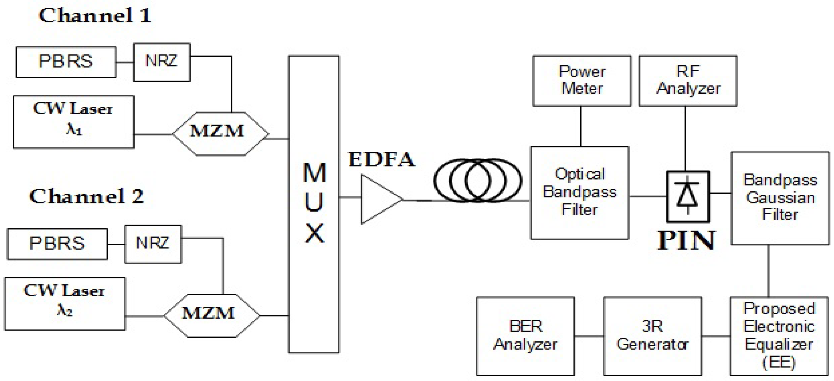
2. Network Layout
To accommodate many users, multi-channel transmission model is one of the promising solutions. However, this model also contributes to the additional dispersion effects of the system. The proposed layout in this work is of an effective equalizer for the OCN, in order to minimize the effects from the optical transmission and increase the system’s performance. In this section, the proposed network architecture is explained, as shown in Figure 1, to demonstrate the system components and their parametric values, which have been used to analyze the multi-channel OCN transmission. The elements such as pseudo random bit sequence (PRBS) generator, continuous wave laser (CWL), non-return to zero (NRZ) pulse shaper, Mach–Zehnder modulator (MZM), optical DWDM multiplexer (MUX), single mode fiber (SMF), erbium doped fiber amplifier (EDFA), optical Gaussian filter, polarization controller (PC) to reduce the polarization dependent losses, positive intrinsic negative (PIN) photodiode, band pass Gaussian filter, signal analyzers, EE, and 3R-regenerator (3R-regenerator means re-amplification, re-shaping and re-timing) are used in the proposed system for simulations.
In the OCNs, the data are transmitted over fiber in the form of light. For each user unit, the PRBS module generates stream of bits and defines the data rate of the system. These generated bits are then converted to electrical signals using NRZ module whose output is given as input to the MZM modulator. MZM is used as an external modulator which modulates the input radio frequency (RF) data signal on to the optical wavelength. The MZM is biased at quadrature point to provide maximum linearity in data modulation. The output of the MZM from each user unit is combined using a DWDM multiplexer, whose output is transmitted over SMF from the central station to the base station. The 16 total channels are combined to make a composite DWDM signal, which is transported over the single fiber link. The fiber consists of constant 0.2 dB/km attenuation losses; hence, increasing the fiber length will result in increasing the propagation losses and, consequently, CD and PMD effects will also be increased. To compensate the attenuation losses, EDFA amplifier (10 dB gain for every 50 km SMF span) is used in the system. At the other end of transmission, an optical filter is used to retrieve the data for a particular user (to perform performance analysis). The use of optical filter, and a RF filter after the PIN diode, removes the out-of-band noise from the user’s data. PIN photodiode is used at the receiver end to convert optical data into electrical signals. Due to high dispersion losses, the data will not be in its original form after covering a long distance. Therefore, equalization techniques have been used to retrieve the original form of data. Re-amplification, re-shaping, and re-timing are the functions embedded in the 3R-regenerator. The purpose of BER analyzer is to investigate received signals in terms of BER, Q-factor and eye-diagrams.
2.1. Electronic Compensation
The electronic compensation technique is used to filter the desired signals from the noisy data at user end. Similarly, it also overcomes the channel effects which are related to the RF processing steps involved at the user end. It is a cost effective approach as additional components are not required for its implementation at both transmitter and receiver end. Electronic compensation does not cause signal attenuation because this type of signal processing is performed at the extreme end of the transmission system, i.e., at the user end. It also provides the flexibility to add new sets of users to the multi-channel model, without affecting the overall downlink set up [21]. All the above-mentioned pros are achieved at the cost of few features, such as limited bandwidth and interference from surrounding devices, as compared to their optical counterparts. Different techniques are used for the electronic compensation process, such as feed forward decision feedback equalizer (FF-DFE) [22], nonlinear FF-DFE (NL-FF-DFE) [23], and maximum likelihood sequence estimator (MLSE) [24]. All these techniques have been studied previously to mitigate the channel effects from wireless transmission. The first two techniques can be used in cascade and are combined as EE to analyze their performance for mitigation of dispersion.
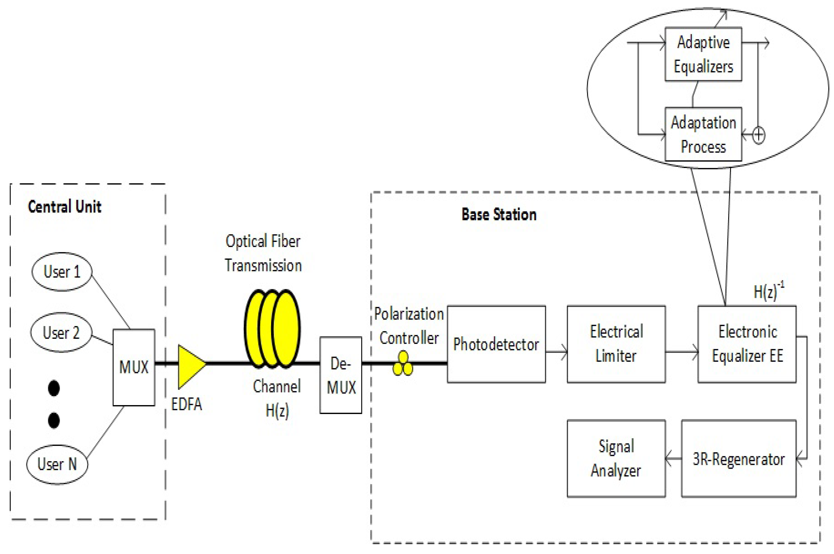
The block diagram of the steps involved at the base station is shown in Figure 2, where EE block is installed at the end of transmission. Figure 2 shows a set of users at the central station and a composite multi-channel signal is formed by combining the output of each user. The multi-channel signal is transported over 300 km of optical fiber to the base station and suffers from severe dispersion effects which are effectively shown as (channel response). At the base station, the signal is recovered by using a wide band photo detector. To compensate the unwanted signals, a combined equalizer is used at the end of the system. The signal analyzer is used to check the signal performance in terms of different performance metrics, such as BER, Q-factor, and eye-diagram. In this paper, we propose the use of EE to be used at the receiver end by employing the electronic equalizer block. At the receiver end, it abates inter symbol interference (ISI) and error free signal is demodulated to obtain the sent sequence. For the simulations, a commercial software package Optisystem was used. The components used in the proposed set up are not available for experimental analysis; hence, Optisystem simulations were used to model the components and obtain results.
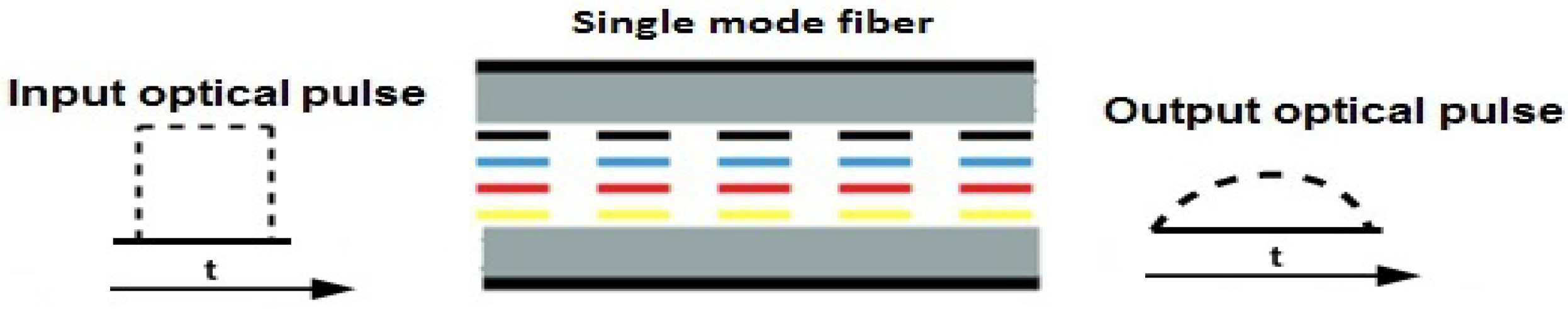
2.2. Chromatic Dispersion
In OCN, each wavelength consists of ON/OFF flashes of light to perform the modulation of data. Spreading of optical pulses phenomenon occurs after traveling through several km in optical medium and this effect is known as dispersion [25]. Different wavelengths travel at slightly different speeds in OCNs. The dispersion which is caused due to variation of core refractive index is known as material dispersion [25]. However, some optical pulses end up in propagating through the cladding of the fiber, where the speed of pulse is different from the speed of light signal in the core. This effect is called wave-guide dispersion. The combined effect of wave-guide and material dispersions gives a common effect known as CD. Pulse broadening problem rises due to CD, as shown in Figure 3. Hence, in this paper, we mitigate CD losses using DEF/FFE techniques.
2.3. Polarization Mode Dispersion
This factor exists in SMF, when orthogonality between the two fundamental modes is disturbed, as shown in Figure 4. These modes are orthogonally polarized and coexist in SMF. A delay time difference occurs among these two orthogonally polarized modes, due to small perturbation inside the optical fiber. The impairments generated by this phenomenon are called PMD [26]. The impairments caused by the dispersion are more severe in the case of multi carrier OCN and, hence, affect the overall optical system efficiency. Therefore, PMD monitoring is needed by using network management or compensation techniques. In this paper, we implement DFE/FFE, Gaussian band pass filter, and Gaussian optical filter to minimize the effects of PMD and CD for multi carrier OCNs. In this section, we highlight the CD and PMD impairments, and the procedures on how to compensate these issues and propose OCN model. In the next section, we discuss technical background of the FFE/DFE techniques, which are used for CD and PMD minimization in multi carrier OCNs.
3. Technical Background
The considered OCN aims to transmit multi carrier signals over long distance, with minimum dispersions effects. We implement FFE and DFE equalization techniques to control the effect of high order dispersion effects in long distance and multi carrier transmission over SMF.
3.1. Feed Forward Equalization
The mitigation of the model dispersion can be achieved at the user end with signal processing, majorly employing adaptive equalization techniques, through which the compensation is achieved when linear time invariant model of the implemented equalizer approaches the channel-response of the SMF. The two similar but opposite responses cancel out the effect of each other and hence the received signal is free from any channel effects. The effects of model dispersion in the form of linear and slow-varying system are given in Equation (1) [27,28]:
where describes modulated signal and can be extended as
Here, denotes pulse shape, z is propagated per bit interval, shows the equivalent impulse response of the transmission fiber, and is the additive noise.
If denotes the convolution of the transmitted pulse with the channel impulse response [29], we can write
As is time-invariant, i.e., = , considering the PBRS output , the can be expressed as follows (Equation (4) [27]:
Thus, an optical matched filter on the receiver side is used to the transmitted pulse . Subsequently, sampling the outcome of this matched filter at intervals, the communicated bit sequence is obtained, i.e,
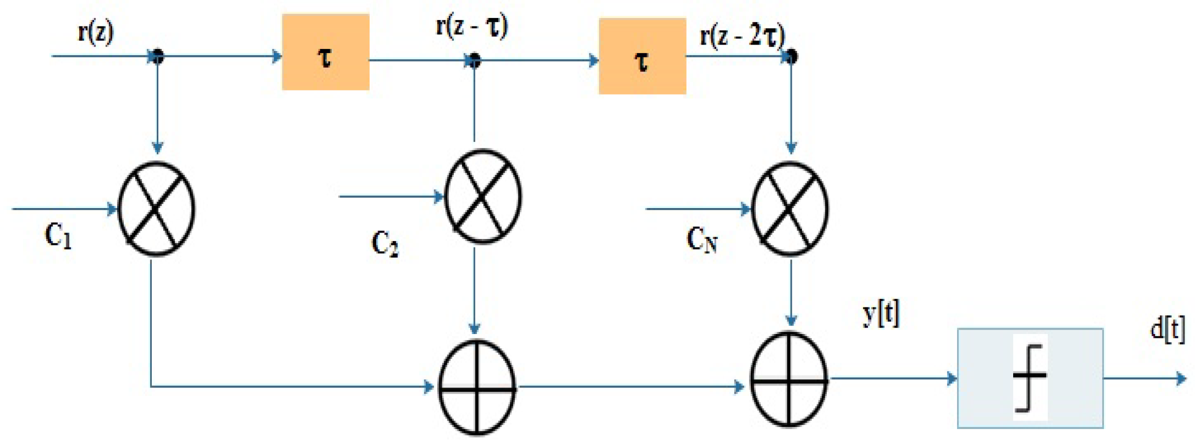
This shows that distortion among the optical pulses can be suppressed by using adaptive equalization [30]. A finite impulse response (FIR) filter is used for the FFE method [31], whose output is shown in Equation (6) as
where the delay-line spacing for N number of taps for the equalizer is Z and the kth coefficient of filter is , which is evaluated by using any of the LMS or MMSE schemes. The schematic diagram of FFE is shown in Figure 5.
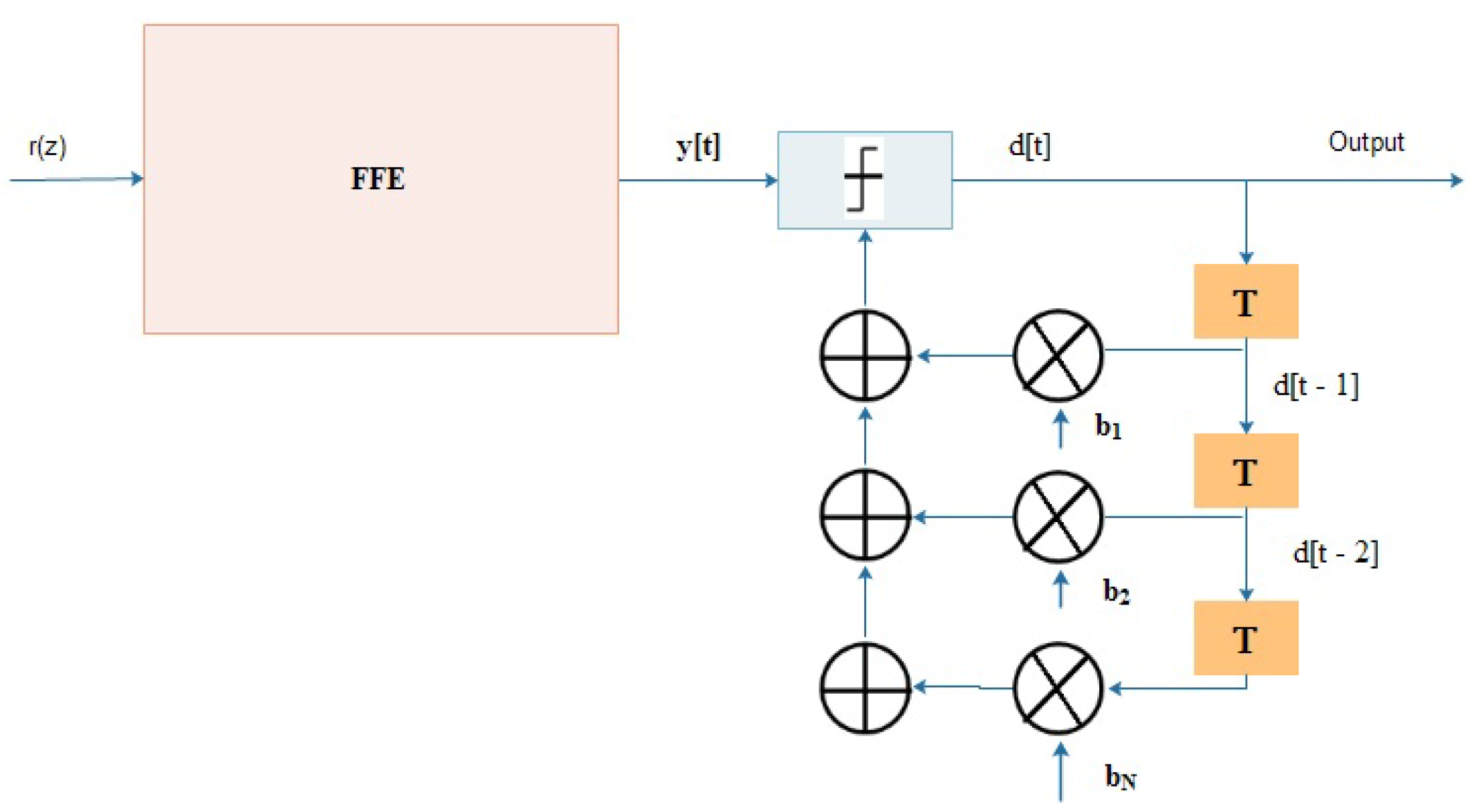
3.2. Decision Feedback Equalization
The equalizer for slow frequency selective channels can be selected to work on the principle of FFE; however, its performance degrades for channels having high spectral width. In contrast, DFE helps to solve wide spectral width problem in transmitted channels. A typical DFE consists of FFE with additional filters, as shown in Figure 6, where it can be seen that extra filters are used for further corrections using the past and current output. DFE takes the output of FFE as an input and further improves the data by using a feedback equalizer. The DFE outcomes with linear feedback filter [32] can be expressed as
where LMS coefficient updates are determined as
Hence, due to the above-mentioned features of FFE and DFE, we use DFE and FFE methods in our proposed work to mitigate CD and PMD.
Analytical modeling of FFE and DFE is presented in this section with the aim to understand their operation in mitigating the channel effects. The next section explains the simulation results based on the network model and theoretical approach.
4. Results and Discussion
This section explains the obtained results from the proposed model. The simulations were performed using Optisystem, which enables designing, analyzing, and simulating optoelectronics and fiber optics used in OCNs. Moreover, it provides scalability through the ease of connection with other softwares such as MATLAB. EE is one of the important parameters which exists in Optisystem software. FFE and DFE techniques are applied by using EE element, whose purpose is to mitigate CD and PMD impairments. The solutions of the proposed model enable high spectral efficiency and flexibility to up-scale the system. The parameters used for the proposed OCN are listed in Table 1.
The graphical results of the simulation data and comparison with and without equalization OCN with 10, 40 and 60 Gbps data rates are presented in Figure 7, Figure 8 and Figure 9. For transmission distance beyond 300 km on a SMF, the results compare received power with BER without and with equalization in Figure 7a–c for 10, 40 and 100 Gbps data rates, respectively. The results show that EE achieves performance gain above 3 dBm for BER between and as compared to an OCN without equalizer after 100 km transmission distance.
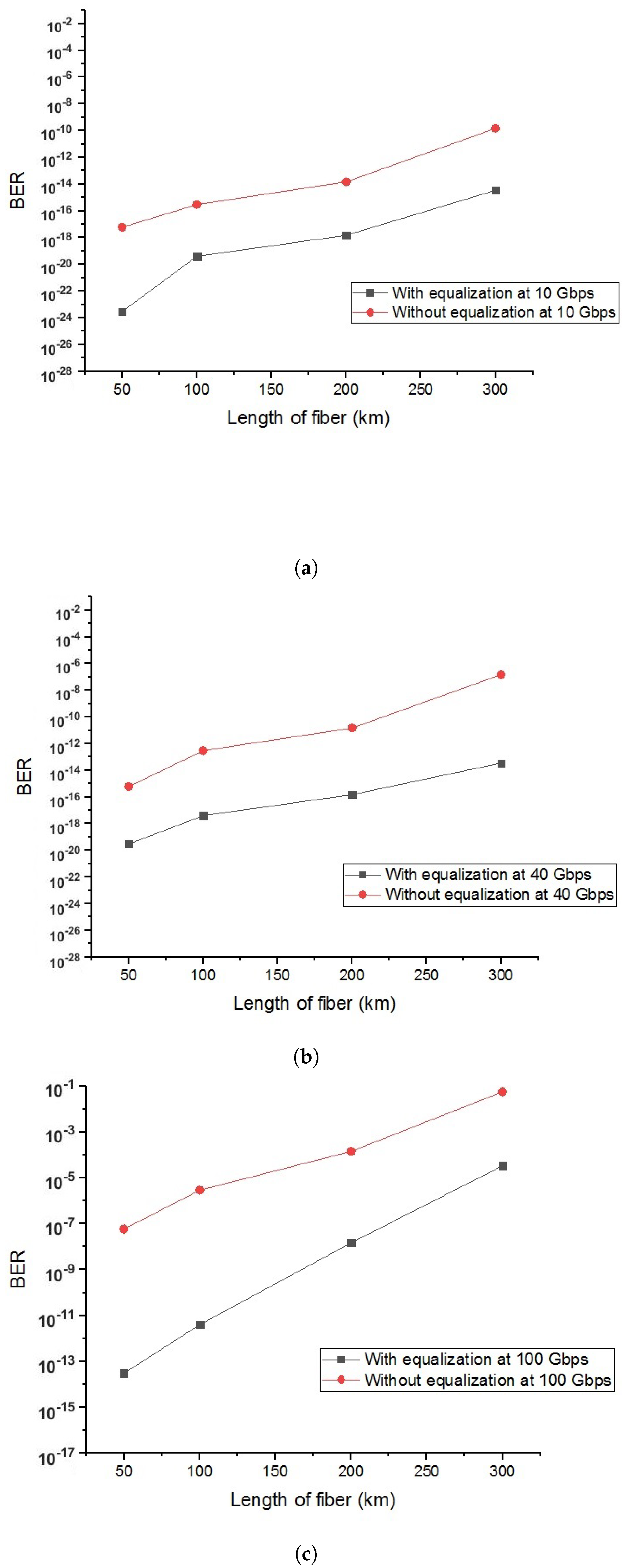
Similarly, Figure 8a–c shows results in terms of BER against transmission length. The results are compared with and without DEF/FFE employed networks at 10, 40 and 100 Gbps speed. From these results, it is clear that the value of BER rises with increasing transmission fiber length. The results also indicate that the performance of the proposed system with set of equalizers is more efficient than without equalizer. Without equalization, the system performance degrades significantly after 100 km length of fiber. Without equalizer, the achieved BER for transmission distance of 50 km is recorded above . However, in contrast, our results show BER below . This is beneficial in terms of high data rate transmission. These figures indicate that the performance gain of the proposed OCN at 10, 40 and 100 Gbps speed are better than without equalization OCN.
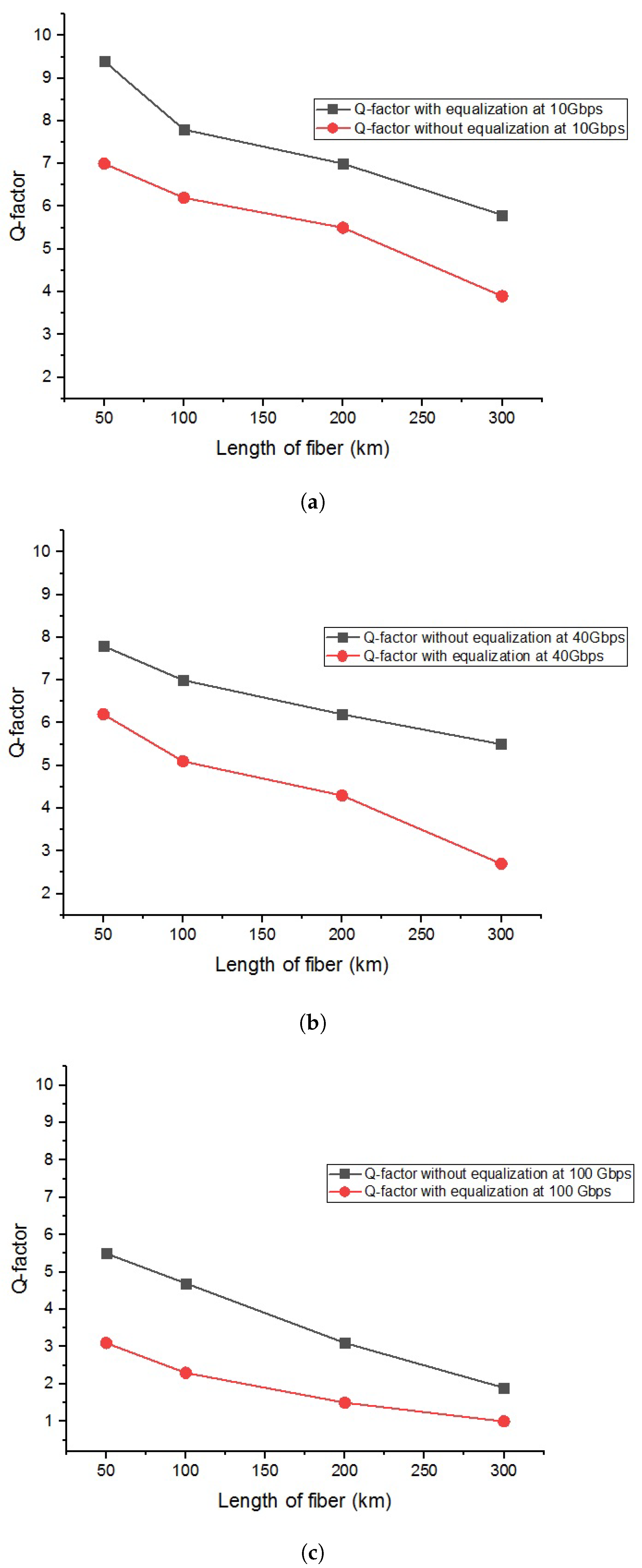
Moreover, we analyzed OCN performance in terms of Q-factor with and without equalization at 10, 40 and 100 Gbps data rates. The results of the proposed OCN are presented in Figure 9a–c in terms of Q-factor against length of the fiber at 10, 40 and 100 Gbps, respectively. The results are accurate below 100 km due to fewer dispersion losses in the considered OCN. Dispersion of the system depends upon the length of the fiber, and rises as the length of the fiber increases, and, hence, the system performance degrades. It is evident from the results in Figure 9a that CD and PMD losses are treated up to 300 km of length with less error by using DFE/FFE based techniques. Similarly, Figure 9a–c displays that the CD and PMD effects become severer at higher data rates. It is also evident from the figures that the tolerance against CD and PMD effects are stronger as compared to the OCN without equalization.
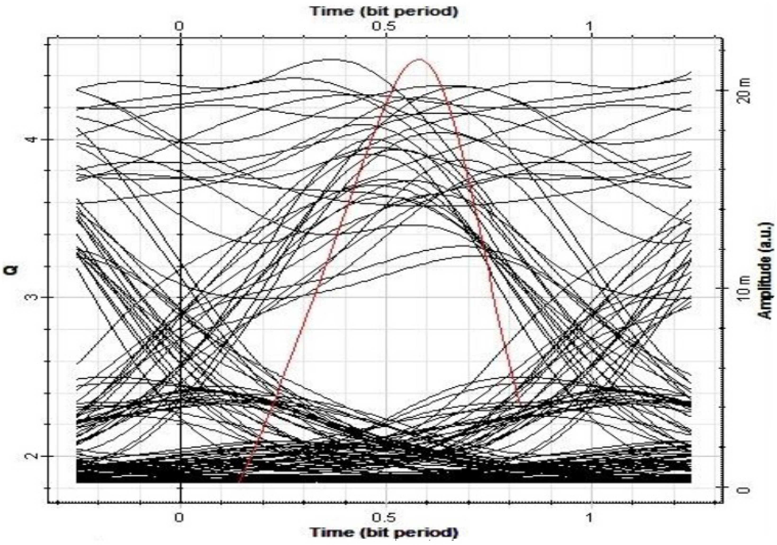
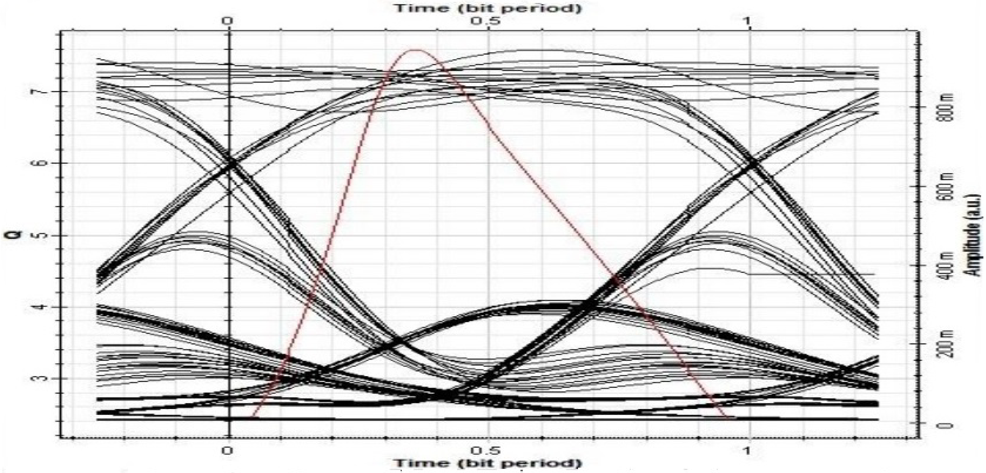
Furthermore, Figure 10 and Figure 11 present eye-diagrams of the results. These open eye-diagrams show improvement in the quality of the received signal. The behavior of the proposed system performance can also be viewed from these eye-diagrams. In these diagrams, many signals are superimposed on each other. From its appearance, various parameters such as noise, jitter, ISI, and signal distortion are estimated. The clear and wide eye shows that efficient and error free transmission has been achieved from the proposed set up. Figure 10 shows that the OCN without equalization presents worse performance as compared to the OCN with equalization depicted in Figure 11. The size of eye opening in Figure 11 is larger than the one in Figure 10, which indicates that the error rate of the proposed model is lower than the system without FFE/DFE employment.
5. Conclusions
An optical fiber system accommodates many users, where they can avail high capacity and data rate services. However, multi carrier OCN faces severe dispersion effects such as CD and PMD losses. In this paper, we use DFE and FFE techniques to compensate these losses in OCNs. These mentioned techniques optimize the existing OCNs and meet the requirements of end users’ high data rate demands. Furthermore, in this paper, performance analyses with and without DFE/FFE equalization for CD and PMD compensation are compared. Moreover, the effect of equalization for pre and post compensation of CD and PMD is investigated. Using adaptive equalization techniques at high data rates, the proposed system achieves significant dispersion compensations in terms of improved BER and Q-factor.
Author Contributions
Conceptualization: F.A. and S.A.; methodology, F.A.; software: S.A, and Z.H.A.; validation: F.M. and Z.H.A.; formal analysis, F.A. and U.H.; investigation: S.A. F.M. and U.H; data curation: Z.H.A.; writing—original draft preparation, F.A., F.M. and S.A.; supervision: F.M. S.K.; project administration: F.M. and and S.K.; funding acquisition: S.K.
Funding
This work (S2666095) was supported by project for Cooperative R&D between Industry, Academy, and Research Institute funded Korea Ministry of SMEs and Startups in 20.
Conflicts of Interest
The authors declare no conflict of interest.
References
- Nazarathy, M.; Tolmachev, A. Subbanded DSP architectures based on underdecimated filter banks for coherent OFDM receivers: Overview and recent advances. IEEE Signal Process. Mag. 2014, 31, 70–81. [Google Scholar] [CrossRef]
- Peppas, K.P.; Boucouvalas, A.C.; Ghassemloy, Z. Performance of underwater optical wireless communication with multi-pulse pulseposition modulation receivers and spatial diversity. IET Optoelectron. 2017, 11, 180–185. [Google Scholar] [CrossRef]
- Xi, J.; Xuan, Z.; Li, L.; Xu, T.; Chen, J.; Song, Y.; Wang, M. Comparison of NRZ and duo-binary format in adaptive equalization assisted 10G-optics based 25G-EPON. J. Opt. Commun. 2018, 410, 328–332. [Google Scholar] [CrossRef]
- Charlet, G.; Pecci, P. Ultra-long haul submarine transmission. In Undersea Fiber Communication Systems, 2nd ed.; ScienceDirect Academic Press: Cambridge, MA, USA, 2016; pp. 165–235. [Google Scholar]
- Hui, R.; O’Sullivan, M. Optical System Performance Measurements. In Fiber Optic Measurement Techniques; Elsevier Academic Press: Cambridge, MA, USA, 2009. [Google Scholar]
- Okamoto, K. Planar lightwave circuits. In Fundamentals of Optical Waveguides, 2nd ed.; Elsevier Academic Press: Cambridge, MA, USA, 2006; pp. 417–534. [Google Scholar]
- Ali, F.; Khan, Y.; Ali, A. Impact of Nonlinear Impairments on Power Budget and Transmission Power Penalties in High Capacity Long Haul Optical Networks. J. Wirel. Pers. Commun. 2019, 106, 1001–1013. [Google Scholar]
- Pilori, D.; Bertignono, L.; Nespola, A.; Forghieri, F.; Mazzini, M.; Gaudino, R. Bidirectional 4-PAM to Double Per-Fiber Capacity in 2-km Intra-Datacenter Link. IEEE Photonics J. 2018, 10, 1–10. [Google Scholar] [CrossRef]
- Cantono, M.; Pilori, D.; Ferrari, A.; Catanese, C.; Thouras, J.; Augé, J.L.; Curri, V. On the interplay of nonlinear interference generation with stimulated raman scattering for QoT estimation. J. Light. Technol. 2018, 36, 3131–3141. [Google Scholar] [CrossRef]
- Gutíirrez, F.A.; Perry, P.; Martin, E.P.; Ellis, A.D.; Smyth, F.; Barry, L.P. All-analogue real-time broadband filter bank multicarrier optical communications system. J. Light. Technol. 2015, 33, 5073–5083. [Google Scholar] [CrossRef]
- Ullah, R.; Bo, L.; Ullah, S. Flattened optical multicarrier generation technique for optical line terminal side in next generation WDM-PON supporting high data rate transmission. IEEE Access 2018, 6, 6183–6193. [Google Scholar] [CrossRef]
- Islam, M.; Ahmed, N. FFT-based universal filtered multicarrier technology for low overhead and agile datacenter interconnect. In Proceedings of the 18th International Conference on Transparent Optical Networks (ICTON), Trento, Italy, 10–14 July 2016; pp. 1–4. [Google Scholar]
- Company, V.T.; Schrider, J.; Flp, A.; Lundberg, L.; Helgason, Ó.B.; Karlsson, M.; Andrekson, P.A. Laser frequency combs for coherent optical communications. J. Light. Technol. 2019, 37, 1663–1670. [Google Scholar] [CrossRef]
- Ullah, R.; Liu, B.; Zhang, Q.; Tian, Q.; Ali, A.; Khan, Y.; Tian, F.; Zia, M.A.; Ahmad, H.; Zhang, L.; et al. Cost effective scheme for OLT in next generation passive optical access network based on noise free optical multi carrier. China Commun. 2016, 13, 76–87. [Google Scholar] [CrossRef]
- Moeneclaey, B.; Blache, F.; Van Kerrebrouck, J.; Brenot, R.; Coudyzer, G.; Achouche, M.; Qiu, X.Z.; Bauwelinck, J.; Yin, X. 40-Gb/s TDM-PON downstream link with low-cost EML transmitter and APD-based electrical duobinary receiver. J. Light. Technol. 2017, 35, 1083–1089. [Google Scholar] [CrossRef]
- Dikhaminjia, N.; Tsiklauri, M.; Kiguradze, Z.; He, J.; Drewniak, J.; Chada, A.; Mutnury, B. Combined Optimization of FFE and DFE Equalizations. In Proceedings of the 27th Conference on Electrical Performance of Electronic Packaging and Systems (EPEPS), San Jose, CA, USA, 14–17 October 2018; pp. 21–23. [Google Scholar]
- Shafik, A.; Tabasy, E.Z.; Cai, S.; Lee, K.; Hoyos, S.; Palermo, S. A 10 Gb/s hybrid ADC-based receiver with embedded analog and per-symbol dynamically enabled digital equalization. IEEE J. Solid-State Circuits 2016, 51, 671–685. [Google Scholar]
- Im, J.; Freitas, D.; Roldan, A.B.; Casey, R.; Chen, S.; Chou, C.H.; Cronin, T.; Geary, K.; McLeod, S.; Zhou, L.; et al. A 40-to-56 Gb/s PAM-4 receiver with 10-tap direct decision-feedback equalization in 16 nm FinFET. IEEE J. Solid-State Circuits 2017, 52, 3486–3502. [Google Scholar] [CrossRef]
- Roshan-Zamir, A.; Iwai, T.; Fan, Y.H.; Kumar, A.; Yang, H.W.; Sledjeski, L.; Hamilton, J.; Chandramouli, S.; Aude, A.; Palermo, S. A 56-gb/s PAM4 receiver with low-overhead techniques for threshold and edge-based dfe fir- and iir-tap adaptation in 65-nm cmos. IEEE J. Solid-State Circuits 2019, 54, 672–684. [Google Scholar] [CrossRef]
- Habib, U.; Steeg, M.; Stöhr, A.; Gomes, N.J. Single radio-over-Fiber link and RF chain-based 60 GHz multi-beam transmission. J. Light Technol. 2019, 37, 1974–1980. [Google Scholar] [CrossRef]
- Kocaman, N.; Ali, T.; Rao, L.P.; Singh, U.; Abdul-Latif, M.; Liu, Y.; Hafez, A.A.; Park, H.; Vasani, A.; Huang, Z.; et al. A 3.8 mw/Gbps quad-channel 8.5–13 Gbps serial link with a 5 tap DFE and a 4 tap transmit FFE in 28 nm CMOS. IEEE J. Solid-State Circuits 2016, 51, 881–892. [Google Scholar]
- Bandiziol, A.; Grollitsch, W.; Steffan, G.; Nonis, R.; Palestri, P. Design and characterization of a 9.2-Gb/s transceiver for automotive microcontroller applications with 8-Taps FFE and 1-Tap unrolled/4-taps DFE. IEEE Trans. Circuits Syst. II Express Briefs 2018, 65, 1305–1309. [Google Scholar] [CrossRef]
- Kiran, S.; Cai, S.; Luo, Y.; Hoyos, S.; Palermo, S. A 32 Gb/s ADC-based PAM-4 receiver with 2-bit/stage SAR ADC and partially-unrolled DFE. In Proceedings of the IEEE Custom Integrated Circuits Conference (CICC), San Diego, CA, USA, 8–11 April 2018; pp. 1–4. [Google Scholar]
- Zhang, K.; Zhuge, Q.; Xin, H.; Morsy-Osman, M.; El-Fiky, E.; Yi, L.; Hu, W.; Plant, D.V. Intensity directed equalizer for the mitigation of DML chirp induced distortion in dispersion-unmanaged C-band PAM transmission. J. Opt. Express 2017, 25, 28123–28135. [Google Scholar] [CrossRef]
- Li, Z.; Shubin, I.; Zhou, X. Optical interconnects: Recent advances and future challenges. J. Opt. Express 2015, 23, 3717–3720. [Google Scholar] [CrossRef]
- Li, F.; Zou, D.; Ding, L.; Sun, Y.; Li, J.; Sui, Q.; Li, L.; Yi, X.; Li, Z. 100 Gbit/s PAM4 signal transmission and reception for 2-km interconnect with adaptive notch filter for narrowband interference. J. Opt. Express 2018, 26, 24066–24074. [Google Scholar] [CrossRef]
- Wang, H.; Li, J.; Kong, D.; Li, Y.; Li, W.; Wu, J.; Xu, K.; Lin, J. Multicarrier group detection in receiver-side duobinary-shaped wdm superchannel systems. IEEE Photonics Technol. Lett. 2012, 24, 1206–1208. [Google Scholar] [CrossRef]
- Shahramian, S.; Carusone, A.C. A 0.41 pJ/Bit 10 Gb/s hybrid 2 IIR and 1 discrete-time DFE tap in 28 nm-LP CMOS. IEEE J. Solid-State Circuits 2015, 58, 1722–1735. [Google Scholar] [CrossRef]
- Bulzacchelli, J.F. Equalization for electrical links: Current design techniques and future directions. IEEE J. Solid State Circuits Mag. 2015, 7, 23–31. [Google Scholar] [CrossRef]
- Stojanovic, N.; Karinou, F.; Qiang, Z.; Prodaniuc, C. Volterra and Wiener equalizers for short-reach 100G PAM-4 Applications. J. Light. Technol. 2017, 35, 4583–4594. [Google Scholar] [CrossRef]
- Alberto, G.; Debora, A.; Pierpaolo, B. Multicarrier approach increases the capacity of optical systems. SPIE Newsroom 2017. [Google Scholar] [CrossRef] [Green Version]
- Pinto, A.N.; Amado, S.B.; Martins, C.S.; Ziaie, S.; Muga, N.J.; Guiomar, F.P. Multi-carrier high-speed optical communication systems supported by digital signal processing. In Proceedings of the 18th International Conference on Transparent Optical Networks (ICTON), Trento, Italy, 10–14 July 2016; pp. 1–4. [Google Scholar]
Figure 1.
Proposed system layout.

Figure 2.
The electronic equalizer framework in multi-channel OCN.

Figure 3.
Signal broadening issue due to chromatic dispersion.

Figure 4.
Modes of propagating pulse in optical fiber.

Figure 5.
Feed forward equalization.

Figure 6.
Decision feedback equalization.

Figure 7.
BER comparison with received power with and without equalization: (a) at 10 Gbps data rate; (b) at 40 Gbps data rate; and (c) at 100 Gbps data rate.
Figure 7.
BER comparison with received power with and without equalization: (a) at 10 Gbps data rate; (b) at 40 Gbps data rate; and (c) at 100 Gbps data rate.

Figure 8.
BER vs. transmission fiber length for the two cases (with and without equalization) (a) at 10 Gbps data rate; (b) at 40 Gbps data rate; and (c) at 100 Gbps data rate.
Figure 8.
BER vs. transmission fiber length for the two cases (with and without equalization) (a) at 10 Gbps data rate; (b) at 40 Gbps data rate; and (c) at 100 Gbps data rate.

Figure 9.
Q-factor results for the transmission fiber length up to 300 km, (a) at 10 Gbps; (b) at 40 Gbps data rate; and (c) at 100 Gbps data rate.
Figure 9.
Q-factor results for the transmission fiber length up to 300 km, (a) at 10 Gbps; (b) at 40 Gbps data rate; and (c) at 100 Gbps data rate.

Figure 10.
BER eye-diagram without equalization.

Figure 11.
BER eye-diagram with equalization.


Table 1.
Simulation parameters and their values used for the proposed model.
| Parameter | Value |
|---|---|
| Number of Channels | 16 |
| Reference wavelength | 1550 nm |
| Attenuation of the fiber | 0.2 dBkm |
| Dispersion | 17 ps/nm/km |
| Line width | 10 MHz |
| Dispersion slope | ps/nm/K |
| 0 ps/km | |
| Effective area | 80 m |
| Bandwidth | 10 GHz |
| Launch power | −10 to 10 dBm |
| Total length of optical fiber | 300 km |
| Channel spacing | 50 GHz |
| Photo detector responsivity | 1 |
| Photo detector’ Dark current | 10 nA |
© 2019 by the authors. Licensee MDPI, Basel, Switzerland. This article is an open access article distributed under the terms and conditions of the Creative Commons Attribution (CC BY) license (http://creativecommons.org/licenses/by/4.0/).
Share and Cite
MDPI and ACS Style
Ali, F.; Ahmad, S.; Muhammad, F.; Abbas, Z.H.; Habib, U.; Kim, S. Adaptive Equalization for Dispersion Mitigation in Multi-Channel Optical Communication Networks. Electronics 2019, 8, 1364. https://doi.org/10.3390/electronics8111364
AMA Style
Ali F, Ahmad S, Muhammad F, Abbas ZH, Habib U, Kim S. Adaptive Equalization for Dispersion Mitigation in Multi-Channel Optical Communication Networks. Electronics. 2019; 8(11):1364. https://doi.org/10.3390/electronics8111364
Chicago/Turabian StyleAli, Farman, Shabbir Ahmad, Fazal Muhammad, Ziaul Haq Abbas, Usman Habib, and Sunghwan Kim. 2019. "Adaptive Equalization for Dispersion Mitigation in Multi-Channel Optical Communication Networks" Electronics 8, no. 11: 1364. https://doi.org/10.3390/electronics8111364
Note that from the first issue of 2016, this journal uses article numbers instead of page numbers. See further details here.