
Biogas Engine Waste Heat Recovery Using Organic Rankine Cycle


1
Department of Industrial Engineering, University of Padova, Padua 35100, Italy
2
Department of Engineering and Management, University of Padova, Padova, Padua 35100, Italy
*
Author to whom correspondence should be addressed.
Energies 2017, 10(3), 327; https://doi.org/10.3390/en10030327
Submission received: 5 February 2017
/
Revised: 1 March 2017
/
Accepted: 4 March 2017
/
Published: 8 March 2017
(This article belongs to the Special Issue Recent Advances in Organic Rankine Cycle Technology for Stationary Applications)
Abstract
:Italy is a leading country in the biogas sector. Energy crops and manure are converted into biogas using anaerobic digestion and, then, into electricity using internal combustion engines (ICEs). Therefore, there is an urgent need for improving the efficiency of these engines taking the real operation into account. To this purpose, in the present work, the organic Rankine cycle (ORC) technology is used to recover the waste heat contained in the exhaust gases of a 1 MWel biogas engine. The ICE behavior being affected by the biogas characteristics, the ORC unit is designed, firstly, using the ICE nameplate data and, then, with data measured during a one-year monitoring activity. The optimum fluid and the plant configuration are selected in both cases using an “in-house” optimization tool. The optimization goal is the maximization of the net electric power while the working fluid is selected among 115 pure fluids and their mixtures. Results show that a recuperative ORC designed using real data guarantees a 30% higher net electric power than the one designed with ICE nameplate conditions.
1. Introduction
The increasing concern about energy resources’ availability and pollution problems have forced international administrations to adopt stringent environmental protection measures and energy efficiency policies.
Renewable energy is the most promising and safest way to mitigate pollution, improve energy security and reduce fossil fuel consumption.
In order to promote wind, solar, biomass, electric vehicles, waste heat recovery and energy efficiency, the governments have established feed-in tariffs.
Although a remarkable contribution to the electricity production is expected to be provided by wind and solar power, the efficient conversion of biomass into electricity is also going to play a key role in the future energy scenario, especially if energy is produced by exploiting the large volumes of unused residues and wastes. In particular, biomass allows meeting various energy needs, including space and process heating, vehicle motion and electricity generation, with the advantage of sustainability, environmental friendliness and good adaptability [1].
For these reasons, several research works have been carried out to classify biomass, estimate its potential, define how the governmental policies can support its sustainable development and how it can be used for power generation [2,3].
Biomass is the result of natural organic processes and includes wood and wood waste, agricultural crops, aquatics plants, algae and agriculture, animal, municipal and food industry wastes. In general, wood is derived from trees while wood wastes are available as sawdust, board ends, bark, etc. Cotton stalks, wheat and rice straw, maize and jowar cobs, rice husks, etc., are classified as agricultural waste, while sugar cane and sugar beets, grains, cassava, sunflower, Jatropha curcas, etc., are crops sown for energy purposes.
As remarked in [1], biomass is the fourth largest energy source in the world and contributes to nearly 14% of the world’s raw energy demand. In the European Union (EU), the use of biomass has increased since the middle of the 1990s due to high subsidies and CO2 emission regulations. As an example, in 2008, biomass covered 3.5% and 2.7% of the EU and North American energy share, respectively, while it still supplies most of the energy needs in developing countries, such as Nepal (97%), Bhutan (86%), Nigeria (85%), Kenya (76%) and Cote d’Ivoire (75%) [4].
The production of power from biomass can occur through external combustion (e.g., boiler) or internal combustion after gasification, pyrolysis, fermentation or anaerobic digestion (e.g., internal combustion engine). The internal combustion is characterized by higher efficiency than the external one, while anaerobic digestion is considered an economic and environmentally-friendly technique compared to other biofuel production processes [5].
Anaerobic digestion is a biological process in which the biomass organic matters, contained in the biogas feedstocks, are degraded into the so-called biogas fuel in an oxygen-free environment [6]. The anaerobic digestion feedstocks need to have a high content of sugar, starch, proteins or fats. For this reason, the feedstock substrates mainly consist of various residues and by-products (the most important are animal manures and slurries collected from farms), but in the last decade, energy crops, such as maize, grasses, beets, sunflowers, etc., grown for biogas production have become the most used feedstock.
The oxygen-free environment, in which anaerobic digestion occurred, is generally called the digester. In the last century, several types of digesters have been developed in order to control the biological processes and the emission of odors, increase the fuel production, stabilize biomass before its agronomic use and reduce the plant cost [7,8]. Actually, the commercially available biogas plants consist of a fermenter, a secondary fermenter, a residue storage tank and a solids feeder.
The fermenter and the secondary fermenter have the same characteristics: a height of 6 m and an internal and external diameter of 23 m and 23.70 m, respectively. In order to maintain a stable digestion process, a constant temperature in the digester is needed. For this reason, digesters are insulated and heated. The reactor heating is done with hot water, which flows along the pipes placed inside the digester wall.
The residue storage tank is annexed to the fermenters and has an internal and external diameter of 25 m and 25.70 m, respectively, and a height of 6 m.
The solids feeder is adjacent to the fermenter, and the tanks are surrounded by a green belt from all sides except one side where the horizontal silos are located [7].
The produced fuel, called biogas, is mainly composed of methane and carbon dioxide. This fuel is the fourth European renewable energy source and has produced more than Wh in 2013. Germany and Italy are the leading countries especially in the agricultural biogas sub-sector [9], but the rapid expansion of this technology has been provoked by the strong feed-in tariffs established, in the last decade, by the European countries’ governments. Note that the Italian renewable support scheme is the most generous in Europe and has produced, on the one hand, a high penetration of renewables, but, on the other hand, an urgent need for flexible power plants fed by fossil fuels [10,11,12,13,14,15,16].
Regarding the biogas conversion into electricity, the following technologies can be employed: a Stirling engine, a gas turbine, a micro gas turbine, high- or low-temperature fuel cells, a combination of a high-temperature fuel cell with a gas turbine, a spark-ignition engine or a dual-fuel engine.
A power unit consisting of an internal combustion engine (ICE) is the preferred solution; in fact, in Europe, 50% are spark-ignition ICEs; about 50% are dual-fuel engines; while fuel cells and micro gas turbines are very seldom to be found [17].
Four-stroke spark-ignition biogas engines were originally developed for natural gas. Then, they were adapted to the special features of biogas. Their capacity normally ranges between 100 kWel and 1 MWel, while the electrical efficiency is in the range 34%–40%. The engine operates at 1500 rpm; its lifetime is about 60,000 h; and the specific investment cost is in the range of 1000–1300 US$/kWel; while the nitrogen oxides (NOx) contained in the exhaust gases need to be controlled and kept below the prescribed values defined by regulations. Usually, to increase the engine efficiency, the biogas engines are supercharged.
Dual-fuel engines (frequently called ignition oil diesel engines) are mainly used in small agricultural plants because they are less expensive and have a higher efficiency than spark-ignition biogas engines in the lower capacity range. Their lifetime is about 35,000 h of operation, but they require an oil analysis every 465 h [17].
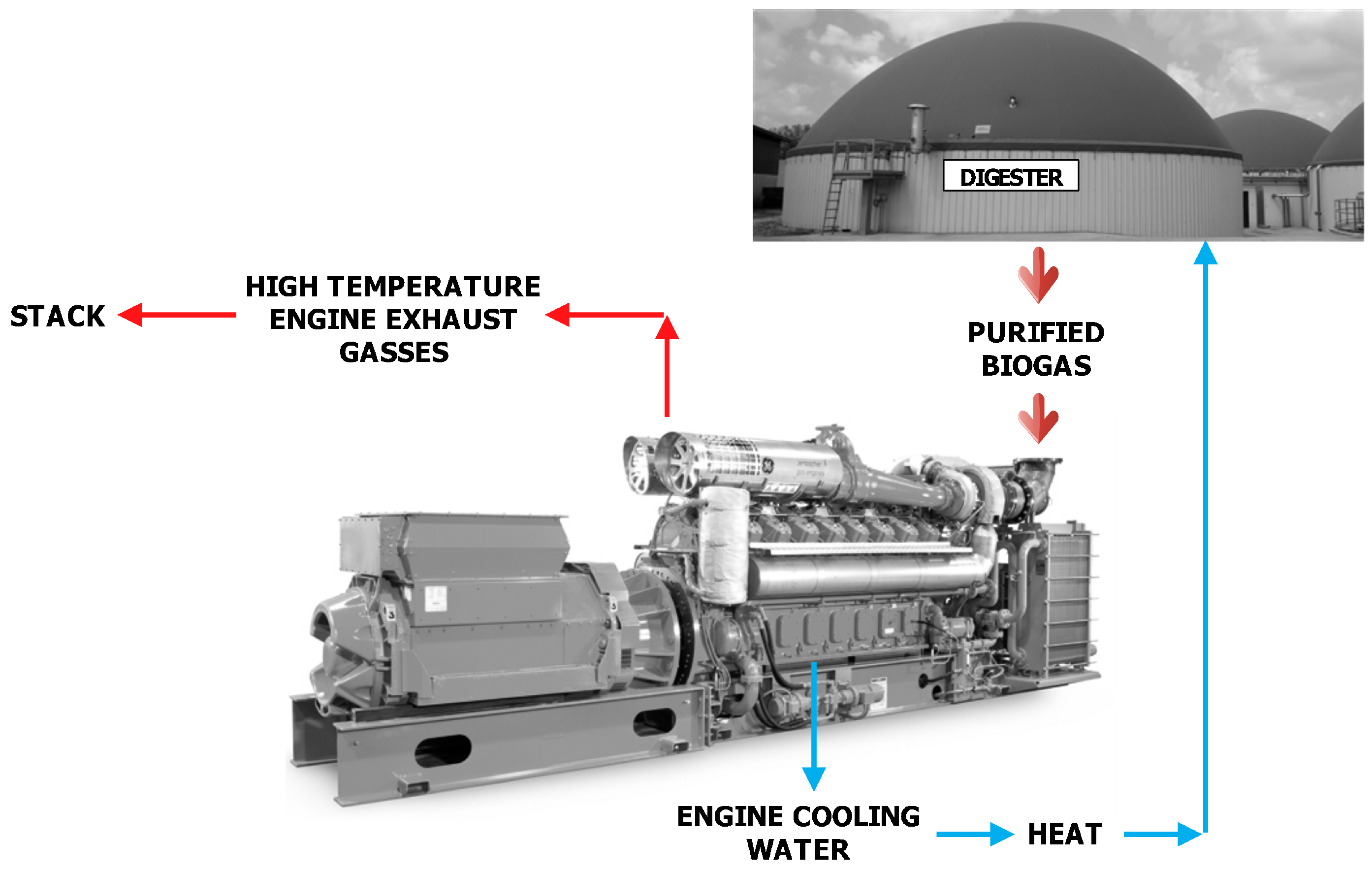
In Italy, the most widespread technology is the spark-ignition engines with a rated power of 1 MWel in which the filtered biogas is burned to produce work. The heat recovered from the engine cooling water is used to maintain the digester required temperature, while the exhaust gases are directly released into the environment with a remarkable waste of heat. A simplified scheme of a biogas plant is depicted in Figure 1.
In the scientific literature, several technologies are available to recover the ICEs’ wasted energy: mechanical and electrical turbo-compounding, thermoelectric materials and organic Rankine cycle [18,19], each one having its own advantages, drawbacks and scale of application. However, the most promising waste heat recovery system is the ORC technology.
Although investigated since the 1880s, organic Rankine cycles have never been popular until today’s growing interest on medium- and low-grade energy recovery systems where cycles using water as the working fluid fail for technical and economic reasons [20,21].
The ORC operates in a similar way as the conventional steam Rankine cycle: the working fluid, which is an organic compound, at high pressure is firstly evaporated, then expanded to a lower pressure, thus supplying mechanical work. The cycle is closed by condensing the low pressure vapor (coming from the expander outlet) and pumping the liquid back to the high pressure. The design of an ORC is a complicated task because the type and temperature of the heat source significantly influence the choice of the working fluid, which in turn determines the configuration, the performance and the economy of the plant [22].
In the scientific literature, several works are dedicated to ORC fluid selection and plant configuration analysis. The use of solar energy as the heat source for the ORC unit is the most investigated field. Delgado-Torres and Garcia-Rodriguez [23] performed an analysis and optimization of a low-temperature solar organic Rankine cycle. The optimization has been done taking the net overall efficiency of the solar power cycle as the objective function while the top temperatures of the solar cycle are considered up to 150 °C using four different solar collector models. Bocci et al. [24] developed a model of a small-scale solar-powered ORC unit for standalone application where the generation unit has thermal solar panels as the heat source, and the needs of the auxiliary items have been covered with photovoltaic modules. Ferrara et al. [25] performed a comparison among different organic fluids, which can be used in small-scale concentrated solar power ORC units where the receiver working fluid is a synthetic oil, rather than a molten salts mixture. Amoresano et al. [26] studied the cycle efficiency optimization of ORC solar plants, while Villarini et al. [27] presented a review of the state of the art of small-scale solar powered ORC systems. The design of an ORC operating with solar heat to produce sanitary water, the thermodynamic performance of regenerative ORC based on flat-plate solar collectors and a supercritical ORC system driven by linear Fresnel reflector solar collector have been investigated in [28,29,30], while the potential of solar-power systems based on ORC technology that convert thermal energy from simple and low-cost non-concentrated or low-concentration collectors to mechanical, hydraulic or electrical energy has been evaluated by Markides [31].
The exploitation of geothermal and biomass heat sources with ORC units is also a well-known research area.
For example, in [32,33], the authors proposed the use of binary ORC for the exploitation of medium-low temperature geothermal sources and performed a thermodynamic and techno-economic optimization considering geothermal sources in the temperature range of 120–180 °C. Shokati et al. [34] compared from energetic, exergetic and exergoeconomic viewpoints the basic dual-pressure and dual-fluid ORCs and the Kalina cycle for power generation from the geothermal fluid reservoir. In these cycles, the temperature, pressure and mass flow rate of the geothermal fluid are considered to be 175 °C, 7 bar and 83 kg/s, respectively. Tańczuk and Ulbrich [35] presented the implementation of a biomass-fired co-generation plant supplied with an ORC as the heat source for a small-scale heat distribution system.
More information about the ORC technology coupled with geothermal or biomass heat sources can be found, for example, in [36,37,38,39,40,41,42,43,44,45].
ORC plants for industrial waste heat recovery [46,47,48,49,50] or for the integration of different renewable heat sources [51,52] have also become really promising research sectors.
Despite the large variety of available works, only a few are focused on internal combustion engines’ waste heat recovery.
For example, in [53], a thermodynamic analysis of an ORC that recovers the exhaust heat of a stationary ICE is presented. Three different working fluids and configurations are considered, and a parametric analysis is conducted in order to determine the optimal evaporating pressures for each fluid. Furthermore, a second law analysis has been carried out to determine the best fluid and cycle configuration. The analysis demonstrated that a 12% power increase can be achieved by matching the engine with ORC, but only a small fraction of the heat released by the engine through the cooling water can be recovered. Furthermore in [54,55] a study of working fluid selection has been presented. In [54], nine different pure organic working fluids are selected according to their physical and chemical properties, while in [55], twenty fluids are considered. In [54], results demonstrated that R11, R141b, R113 and R123 show the highest thermodynamic performances, but R245fa and R245ca are the most environmentally-friendly working fluids. The analysis presented in [55] additionally showed that R141b, R123 and R245fa bring the highest thermal efficiency and net power output per unit mass flow rate of hot exhaust. These fluids also have the lowest electricity production cost and ratio between the total heat transfer area and the net power output. In [56], the aim of the work is to design an ORC able to exploit the heat delivered to the cooling water. Six configurations using ten non-flammable working fluids have been considered while their performances (efficiency, safety, cost and emissions) have been evaluated. Results showed that the double regenerative ORC configuration using SES36improved the maximum net efficiency (7.15%), while the single regenerative ORC using R236fa and the reheat regenerative ORC adopting R134a provided a net efficiency of 6.55%. SES36 incremented the ICE electrical efficiency up to 5.3%, while R236fa and R134a provided an increment of 4.9%. The study and analysis of the ICE waste heat energy followed by a theoretical investigation on the feasibility of introducing a waste heat recovery unit (WHRU) in a two-stage turbocharged engine have been presented respectively in [18,57], while the transient operation of an ICE with Rankine WHRU has been analyzed in [58]. The adoption of a dual loop ORC system to recover the waste heat from a heavy-duty compressed natural gas engine is analyzed in [59], while the part-load performance of the ORC that recovers the exhaust gases of a gaseous fuel engines is presented in [60]. In [61], a particle swarm optimization algorithm is used to optimize the operating parameters of a recuperative ORC system, which recovers the heat of a diesel engine, while in [62], the ORC technology is used to generate heat and power from the waste heat of a Suezmax-size oil tanker’s main engine. For a clear overview of the history of ICE exhaust waste heat recovery focusing on ORCs expander and working fluid selection, see, e.g., [63].
Regarding biogas plants coupled with ORCs, only a few investigations are available in the scientific literature. For example, Schulz et al. [64] and Niemczewska [65], suggested to apply the ORC technology to biogas plants with an output power exceeding 300 kWth and where there is no heat demand. They also remarked that about 20% of the thermal energy from the associated CHP generation is available for the ORC process. In practice, they recommend to use the ORC without a heat application. Kane et al. [66] proposed to increase the electrical efficiency of a small biogas engine with a bottoming cycle based on the scroll expander organic Rankine cycle, while Saravia et al. [67] studied the possibility of retrofitting an existing ICE fed with landfill biogas with an ORC. In the first case, a 200 kWel biogas engine is used, while the second plant is equipped with 16 ICE modules, each one with a nameplate power of 1059 kWel. The energetic performance of an ORC system fed by the heat generated from the integrated aerobic/anaerobic treatment of organic waste has been analyzed by Di Maria et al. [68], while the greenhouse gas reduction potential that can be achieved by recovering with an ORC the waste heat released from a biogas engine has been evaluated by Uusitalo et al. [69]. Finally, Meinel et al. [70] proposed an innovative two-stage ORC configuration to recover the ICE waste heat. The ICE is fed with biogas from a biomass digestion plant, while the heat is recovered from the exhaust gases at 490 °C and 1 bar. Despite the slightly higher constructive complexity, the analysis showed an increment of the thermodynamic efficiency in comparison to the conventional ORC scheme.
Starting from the above-mentioned survey of the literature, it is clear that the insertion of an ORC boosts the engine performance and that ORC, which recovers ICE waste heat, is a hot research topic; but, especially in the biogas sector, ORCs are not a commercially available technology, and only a few demonstration units are in operation. In addition, there is a lack of the optimum fluid and plant configuration that have to be employed in biogas engines with a rated power of 1 MWel.
For these reasons, the aim of the present work, is to perform a fluid selection and a plant configuration design of an ORC that recovers the heat contained in the exhaust gases of a 1 MWel biogas engine. This is a real biogas ICE unit operating in the Italian liberalized electricity market. The plant is part of an ongoing research project that has the aim of monitoring the biogas engine emissions and evaluating the possibility of recovering the waste heat. At the time of writing, 20 biogas plants were involved in the project. Each unit is characterized by an ICE with a rated power of 1 MWel, and only one of them is equipped with an ORC with a rated power of 70 kWel.
The main novelty of this work consists of the comparison between the ORC unit designed based on the engine nameplate data and the one designed from engine measured data. After a one-year monitoring activity, the authors have verified that biogas engines operate at full load (1 MWel) for up to 8000 h, but with an engine exhaust mass flow rate and temperature really different from the nameplate ones. This fact has been observed in all of the monitored biogas plants, and it is caused by the anaerobic digestion process, which is different for each biogas unit, while the engines and their nameplate characteristics are exactly the same. To the authors’ knowledge, no one has performed a similar analysis.
2. Case Study
The case study is the power system installed on a biogas plant located in Northern Italy. The plant is composed of a reception tank, four digestion vessels (two fermenters and two secondary fermenters), a gas holder, an overflow tank and the biogas engine. The biogas internal combustion engine is a GE power unit [71] with the following technical data (see Table 1).
To maintain the digester required temperature (38–42 °C), part of the heat contained in the engine cooling water is recovered while the heat contained in the exhaust gases is directly rejected into the environment. Note that the higher incentives are assigned if the plant production is lower than 1 MWel. In fact, the engine net electrical power is maintained equal to 999 kWel. If a waste heat recovery unit were installed, the plant net electrical power would exceed the limit. Therefore, the incentives would be lower. For this reason, the majority of the Italian biogas engines are units in which the heat contained in the exhaust gases is not recovered. However, in very limited cases, an ORC unit is installed, and the ORC turbo-generator has a design power of 70 kWel. In these cases, the engine is de-rated at 930 kWel, while the ORC produces 70 kWel. Obviously, the engine works at part-load, and its efficiency is lower than at the design point condition; but, the plant total production is lower than 1 MWel, and a higher incentive is obtained.
Despite this issue, in future renewable energy policy, it is expected that additional incentives will be assigned to plants whose output exceeds 1 MWel because they recover the exhaust gases’ heat and produce additional electrical energy. Therefore, there is an urgent need for analyzing biogas plants’ real behavior to estimate the waste heat recovery potential and to properly design the waste heat recovery unit. Note that it is not feasible to use the engine waste heat to produce, e.g., hot water or steam using a heat exchanger because it is difficult to find an end-user that requires a nearly constant heat production. Therefore, the only option is to recover the heat and produce electrical energy. However, there are applications in food and diary production processes where the heat demand is quite constant over the year, and then, the feasibility of cogeneration become a really promising option to improve the process efficiency [3,72].
The considered biogas plant has operated in the Italian liberalized electricity market since 2012; it is maintained at full load and, usually, works 8100–8300 h per year.
After a one-year monitoring activity, in which the authors have analyzed the feedstock, digester diet, biogas production, engine combustion and emissions of 20 units fed by different energy crops and manure, but built up with the same ICE and digester units, they have observed that the fuel, air and exhaust gases’ mass flow rate and temperatures are really different from the nameplate ones. The exhaust gases’ mass flow rate and temperature are generally 20% and 10% higher than the nameplate values, respectively. In fact, in the case study, the exhaust gases’ mass flow rate and temperature at nameplate conditions are 5312 kg/h and 457 °C, while the average measured ones, during a one-year monitoring activity, are respectively 6477 kg/h, and 503 °C. These average measured values show a very low standard deviation, respectively 126 kg/h and 10 °C, because the engine operating conditions are almost constant over the year.
The discrepancies between nameplate and measured data are caused by the following parameters:
- The variability of the biomass feedstock, which influences the biogas properties and, consequently, its combustion.
- The calibration of the engine. As clearly presented in [17], during the combustion process, several chemical reactions take place, and different reaction products are developed depending on the oxygen and nitrogen concentrations, the pressure and temperature. These products are mainly NOx, CO and particulate (dust and unburned carbon) and can be found in the exhaust gases. In Europe, the engines’ exhaust gases’ emissions are subjected to limitations, but the limits are different among the European countries. In particular, in Italy, each region has its own regulation, which, sometimes, changes from one year to another. Therefore, each biogas plant has been authorized with different concentrations of NOx, CO and particulate. For this reason, each engine is calibrated to abide by its own limits. However, this affects the exhaust gases mass flow rate and temperature.
Based on this evidence, the authors have decided to investigate the effects of these parameters on the waste heat recovery unit design.
3. Methodology
This part of the paper presents, in Section 3.1, the optimization tool developed to design the ORC units, while in Section 3.2, the optimization settings and the assumed parameters are listed.
3.1. The ORC Plant Designer
The ORC Plant Designer (ORC-PD tool) is an “in-house” optimization code, implemented in the MATLAB environment, able to select the appropriate working fluid and plant architecture starting from different types of heat sources [73]. The optimization is performed employing the genetic algorithm available in the MATLAB optimization toolbox [74].
The ORC-PD tool has been built in such a way that, with a single mathematical model, it is possible to design ORC modules operating with low-temperature (i.e., geothermal, solar, etc.) or medium-high-temperature heat sources, including the exhaust gases released by, e.g., a gas turbine or an internal combustion engine.
Obviously, to cover this wide range of heat sources, appropriate working fluids and plant configurations need to be implemented into the code. For this purpose, a set of 115 pure fluids (including hydrocarbons, hydrofluorocarbons, perfluorocarbons, siloxanes, etc.) that can be good candidates for several types of ORC units have been added. These fluids are not available in a unique database; therefore, the ORC-PD tool is linked with the Reference Fluid Thermodynamic and Transport Properties Database (REFPROP) [75] and CoolProp [76] databases. The use of two databases guarantees a larger number of fluids and compensates the lack of fluids that can occur using a single database.
Pure fluids are good working medium candidates, but as presented in several works (see, e.g., [77,78,79]), also zeotropic mixtures are suitable candidates due to their non-isothermal phase transitions during vaporization and condensation. For this reason, the possibility of adopting the mixture is also included in the tool. Obviously, it is inefficient to test all of the possible combinations among the implemented pure fluids. Hence, the method proposed in [80] is used to select the suitable mixtures components. As discussed in [81], the method was developed for cryogenic refrigerants, but it is also applicable to other fluids. A brief description of the method is given below. The first requirement is that the first mixture component is volatile at 1–1.5 bar. In this manner, low temperatures can be obtained after the expansion process without the need to reach vacuum pressures. The second requirement is that the boiling point of the second component exceeds both the desired average condensation temperature and the boiling point of the first component. As underlined in [81], by adding a component with a higher boiling point, more heat can be absorbed per unit of fluid mass. Hence, the ORC medium mass flow rate can be lower [80].
Following the above-mentioned method, hydrocarbon, hydrochlorofluorocarbon and siloxane mixtures are included in the tool. Note that in the CoolProp database, several mixtures are pre-defined; therefore, these mixtures can be directly selected from the ORC-PD tool list of fluids.
Different types of heat sources require different types of working fluids, but also different plant configurations. At the time of writing, in the “ORC-PD tool”, the following plant architectures are implemented: basic scheme and recuperative configuration, two-stage plant [70], regenerative and recuperative architecture [82], dual pressure levels and dual fluid schemes [34].
In the above-mentioned configurations, the heat source medium and the ORC fluid streams exchange heat directly, but, if the ORC medium is a flammable substance and the heat source temperature is really high, an intermediate thermal oil loop needs to be incorporated to avoid risky contacts between the heat source medium and the organic fluid. In this way, also flammable organic media can be adopted. In the ORC-PD tool, the schemes with the intermediate oil loop are also implemented. All of the proposed cycles can be subcritical or transcritical. Note that the adoption of a subcritical or transcritical cycle and the need of superheating the working fluid are optimization process results.
Several objective functions, such as net electric power, thermal or exergetic efficiency, net present value, etc., can be selected and optimized adopting a single or multi-objective optimization approach.
The tool input parameters are: heat source medium, inlet temperature (), pressure () and mass flow rate () of the heat source, pump isentropic efficiency, pump mechanical efficiency, electric motor efficiency, expander mechanical efficiency and electric generator efficiency; while the variables that are optimized, for each working fluid, by the ORC-PD tool are:
- The heat source outlet temperature, .
- The evaporation pressure of the organic medium, .
- The turbine inlet temperature, TIT.
- The ORC medium concentration if the fluid is a mixture, .
- The minimum temperature difference in the main heat exchanger, .
- The minimum temperature difference in the recuperator if it is present in the cycle, .
- The minimum temperature difference in the condenser, .
- The recuperator efficiency if the components are included in the cycle, E.
- The condensation temperature, .
The isentropic efficiency of the expander is estimated by the axial and radial flow turbines’ efficiency charts developed by Macchi and Perdichizzi [83] and Perdichizzi and Lozza [84], respectively. During the optimization process, the optimizer computes the size parameter and the volumetric flow rate, as defined in [83,84], then interpolates the efficiency charts and computes the turbine isentropic efficiency for both the axial and radial configuration, respectively. The higher isentropic efficiency is selected by the tool to perform the rest of the optimization.
Each heat exchanger is discretized in “n” elements, and for each element, the tool computes the thermodynamic states of the two streams and performs the pinch point violation check. To better match the hot fluid profile with the cold one, the pinch point position is variable. A high discretization of the heat exchangers is therefore needed to identify the pinch point position and avoid pinch point violations. The non-predefined pinch point position and the non-fixed pinch value in all of the ORC heat exchangers are innovative features implemented in the ORC-PD tool. The method of Bell and Ghaly [85] is used to correct the heat transfer coefficient obtained by Shah [86] in the case of mixtures.
Several checks are implemented in the code to avoid pinch point violation in the heat exchangers, the presence of liquid at the turbine inlet, a low value of steam quality at the turbine outlet and that the evaporation process starts in the recuperator. In addition, other checks are introduced to detect numerical issues caused by bad evaluation of the fluid thermodynamic properties acquired from fluid databases.
To sum up, after the inputs definition, for each working fluid candidate and each plant layout, the design-point analysis is performed in order to determine the thermodynamic cycle that maximizes the objective function. Then, an exergetic and economic analysis is also performed.
Note that, in the developed tool, the user can select to perform or not the exergetic and economic analysis and the cooling system method: cooling tower or water-based architecture. In the first scheme, the condenser is fed with water that is then cooled down in a cooling tower, while in the case of a water cooling system, it is assumed to get the water from a river or the sea. In both cases, in the economic analysis, the devices’ investment and operating costs are taken into account.
For the sake of compactness, refer to [73], for the energy, exergy and economic equations implemented in the ORC-PD tool and for the validation process results.
3.2. Optimization Settings
The aim of the present work is to design an ORC unit able to recover the exhaust gases released by a biogas internal combustion engine and comparing the ORC turbo-generator designed from ICE nameplate data to the one designed with measured ICE data.
The optimization goal is the maximization of the net electric power () produced by the ORC.
In both cases, the hot source fluid is modeled as a mixture of nitrogen, oxygen, water, carbon dioxide and argon. The mass flow rate and temperature of the exhaust gases considered in the analysis are listed in Table 2.
The exhaust gas components’ concentration and their pressure at the ICE outlet section cannot be published because these are confidential data, as well as the engine data measured during the one-year monitoring activity.
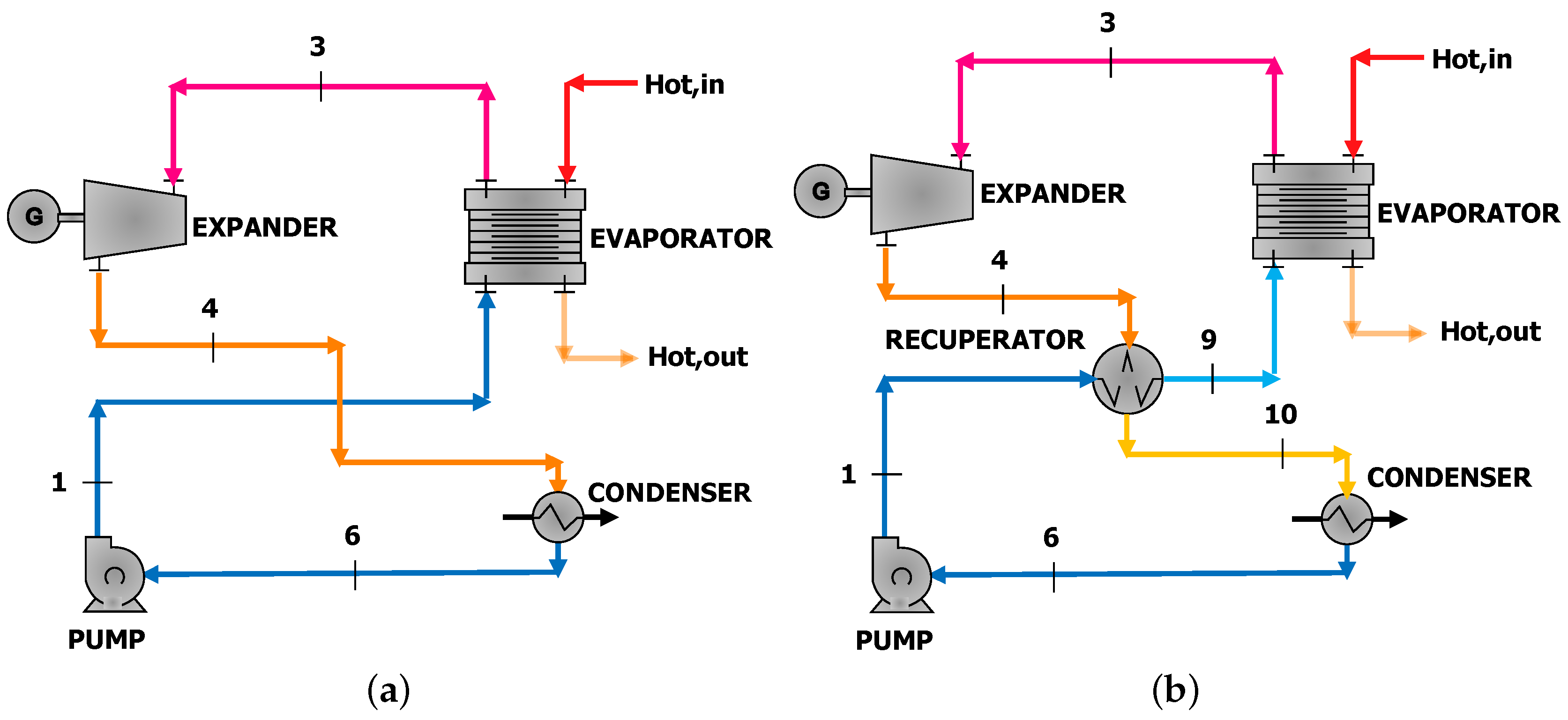
Regarding the ORC architectures, the authors have considered only the basic and the recuperative configurations in order to reduce the plant cost and complexity. Being that the recuperator efficiency is a variable that is optimized by the tool, in practice, the ORC configuration is also a result of the optimization process. In Figure 2, the possible ORC architectures are depicted.
The assumed parameters based on both data available in the scientific literature and plant manufacturers’ knowledge are listed in Table 3, while the upper and lower bound (UB and LB) fixed for the variables that are optimized are listed in Table 4.
and are the condensation and critical temperature of the working medium, respectively, while TIT is the turbine inlet temperature. assumes the value of + 10 °C, while assumes the lower value among the ones computed from the following equations:
is the maximum temperature at which the fluid is defined in the REFPROP/CoolProp database, while is the maximum temperature at which the fluid thermochemical stability is guaranteed.
As pointed out in [87,88], the thermal stability of the organic fluid is a key parameter; therefore, if the decomposition temperature is available in the scientific literature, is set equal to this value. For example, for cyclopentane, is set equal to 300 °C as suggested in [89].
The minimum temperature difference in the heat exchangers strongly affects the design and, consequently, the cost of the devices. For these reasons, different values for the lower bound have been selected in the case of evaporator, recuperator and condenser. The highest value has been assumed in the evaporator in order to design a heat exchanger with an acceptable volume, while the smallest value has been assumed for the condenser. In this way, it is possible to reduce the condensation temperature despite the adoption of a cooling tower.
Solutions that violate the minimum acceptable temperature difference or other constrains are automatically erased.
The minimum admissible steam quality at the turbine outlet is set equal to 0.85, while each heat exchanger is discretized in 100 elements to better characterize the heat transfer process. It is also assumed that the condenser is fed by cold water coming from a cooling tower, which operates with an inlet temperature of 20 °C. For this reason, the optimizer computes the water and air mass flow rates that guarantee the condensation temperature and the purchasing cost of the cooling system.
Due to the lack of the renewable energy policy, in the present work, it is not feasible to perform the economic analysis to compute, e.g., the simple pay back time and the levelized cost of energy of the designed ORC. Therefore, the authors only perform a cost analysis (using the equations reported in [73]) to estimate the ORC purchasing cost.
The genetic algorithm parameters are specified as follows: population size 250, generation size 250, crossover fraction 0.8 and migration fraction 0.2. These numerical values are selected to ensure the repeatability of the results. Note that, e.g., adopting a population of 350 instead of 250 increases the computational time by 55%, but the accuracy remains the same in terms of plant configuration and thermodynamic cycle points.
4. Results and Discussion
Firstly, the ORC unit has been designed using the nameplate data of the engine: an exhaust gases mass flow rate equal to 5312 kg/h and a temperature of 457 °C. The three most promising mixtures and pure fluids are listed in Table 5 and Table 6, respectively.
The use of mixtures or pure working fluids does not affect the plant layout and turbine design. In both cases, the optimized ORC architecture is the recuperative one, while the expander is a radial turbine.
The insertion of a recuperator as the liquid preheater between the pump drain and the expander outlet section essentially increases the plant thermal efficiency. Thus, a higher power output can be obtained. Despite these advantages, this component increases the plant complexity and cost.
Toluene is the pure working fluid, which guarantees the highest net electric power, while the most promising mixture consists of cyclopentane and heptane (0.7/0.3). This mixture supplies lower net electric power than using pure toluene; therefore, pure fluids allow one to reach higher electric power than mixtures. This result is in accordance with previous investigation because mixtures are generally better than pure fluids with low- and medium-temperature heat sources due to the temperature glide at evaporation and condensation that reduces the irreversibilities at phase change. However, several ongoing research projects are investigating the mixture components and concentrations, which allow one to improve the efficiency when the heat source is at medium- and high-temperature.
The design of a waste heat recovery unit with ICE nameplate data allows one to produce an additional electric power of 98.4 kW with an ORC efficiency of 17.2%. This electric power is 28.9% higher than the one that is installed in the few biogas plants equipped with the ORC (generally 70 kWel). As previously said, to receive the highest incentive, the engine is de-rated, and the ORC is undersized. In this way, much energy is wasted even if a WHRU is installed.
Apart from this issue, it is important to notice that, despite the lower net electric power (less than 3%), using benzene allows one to reduce the turbine inlet temperature and increase the condensation pressure. The two effects reduce the plant complexity and, consequently, the purchasing cost. Based on the performed cost analysis, a plant using benzene is 5% less expensive than one employing toluene.
The ORC unit is, then, designed using measured data (exhaust gases mass flow rate equal to 6477 kg/h and an exhaust gases temperature of 503 °C). Table 7 and Table 8 list the optimization results.
As previously (ICE nameplate data), the highest net electric power is reached adopting a pure working fluid instead of a mixture; the ORC is a recuperative unit, and the expander is a radial machine. The comparison among the pure fluids show that toluene allows one to produce the highest net electric power. However, from a thermodynamic point of view, this medium is a good working fluid candidate because it maximizes the net electric power, but is characterized by low condensation pressure: 0.14 bar; a value that is difficult to obtain with acceptable costs and low plant complexity. In fact, the cost analysis shows a condenser purchasing cost 18% higher than in the case of benzene.
The comparison between the ORC unit design with ICE nameplate data and the one with measured data immediately shows that the monitoring activity guarantees designing an ORC able to produce a higher net electric power (28.6%). This fact is strictly related to the engine combustion process, which in turn is affected by the biogas characteristics. However, biogas production and quality are affected by the anaerobic digestion process, which is influenced by the plant diet. Based on the authors’ monitoring activity, in each biogas plant, different quantities, qualities and types of biomass are introduced into the digester. Therefore, each plant has its own biological processes and, then, a particular engine calibration. However, this in turn means a different waste heat recovery unit. The comparison between commercially available ORC for biogas application (70 kWel) and the one designed with measured data (137.8 kWel) clearly shows that only 50% of the available heat is recovered with commercial ORCs. Therefore, this investigation underlines the need for designing the waste heat recovery unit after the biogas plant start up and a monitoring activity.
Based on the experimental activity and the performed optimization, the ORC that better exploits the engine exhaust gases is the one that adopts a pure fluid (toluene), while the plant layout is a recuperative configuration.
The expander is a radial turbine with an estimated isentropic efficiency and rotational speed of 69.7% and 12,000 rpm, respectively. Considering the results of the cost analysis, it is possible to estimate the ORC unit cost equal to 2550 Euro/kW, while, at the time of writing, it is not feasible to perform a realistic economic analysis that predicts, e.g., the simple pay back time and the levelized cost of energy of the proposed configuration.
The ORC plant employing toluene is, again, from the thermodynamic viewpoint, the unit that guarantees higher net electric power. However, from a technical and economical point of view, the ORC that uses benzene is better due to its lower turbine inlet temperature and higher condensation pressure. For these reasons, the authors suggest to implement this ORC instead of the one that uses toluene. The cycle representation in the T-sdiagram and the evaporator T-Qdiagram of the proposed solution is depicted in Figure 3, while the estimated ORC purchasing cost, the radial turbine isentropic efficiency and rotational speed are, for this ORC, 2500 Euro/kW, 69.6% and 18,000 rpm.
5. Conclusions
Italy is a world leader in the electricity production from biogas with an overall installed power up to 400 MWel. The non-cogenerative internal combustion engine is the leading technology, but with this plant architecture, a large quantity of heat is wasted at medium and low temperature. For this reason, in the present work, the insertion of an organic Rankine cycle is suggested to recover the engine exhaust gases’ heat. Being that the engine behavior is influenced by the biogas plant feedstock, the ORC unit is, firstly, designed using the engine nameplate data and, then, with data acquired during a one-year monitoring activity.
Simulation results show that pure fluids allow one to design ORCs with higher net electric power than mixtures. In both cases, toluene guarantees producing higher net electric power than benzene, while designing the ORC unit with real data increases the ORC net electric power by 28.6%. However, the cycle that adopts toluene is characterized by higher turbine inlet temperature and lower condensation pressure than the one employing benzene. A fact that increases the ORC purchasing cost and the plant complexity. Therefore, from a technical and economic point of view, the adoption of benzene instead of toluene is a preferable option.
Compared to the few commercially available ORC units installed in biogas plants, the proposed ORC produces a net electric power that is 50% higher. Therefore, starting from the results of the present work and considering the high number of biogas engines in Italy, it is possible to conclude that there is a great potential in the Italian biogas sector in terms of energy efficiency, waste heat recovery and opportunities for industries that want to develop ORCs.
Note that these ORCs need to be designed with measured data and not nameplate ones, because each engine is calibrated based on the biogas composition, which in turn is affected by the biomass feedstocks. In addition, there is an urgent need for a new renewable energy policy that introduces additional feed-in tariffs for the electricity produce from these waste heat recovery units in order to improve the biogas sector sustainability.
In future works, the off-design and dynamic behavior of the designed unit will be analyzed, as well as the influence of the waste heat recovery unit on the biogas engine emissions reduction.
Acknowledgments
The authors acknowledge “Fondazione Cariverona” for selecting and financing the research project named “STUDIO PER L’IMPLEMENTAZIONE DELLE FERMENTAZIONI ANAEROBICHE A FINI ENERGETICI E ANALISI DEL LORO IMPATTO AMBIENTALE”.
Author Contributions
All the authors contributed to the work in this manuscript. Alarico Macor and Alberto Benato conceived and designed the experiments while Alberto Benato, that is the main author, established the ORC optimization model, performed the model validation and simulation and wrote the paper. All authors provided support and gave useful suggestions during the whole work. In addition, all authors revised and approved the manuscript.
Conflicts of Interest
The authors declare no conflict of interest.
Nomenclature
| crit | critical |
| EU | European Union |
| ev | evaporation |
| eva | evaporator |
| Hot | hot |
| ICE | internal combustion engine |
| in | inlet |
| mass flow rate (kg/h) | |
| max | maximum |
| min | minimum |
| ORC | organic Rankine cycle |
| ORC-PD | Organic Rankine Cycle Plant Designer |
| out | outlet |
| p | pressure (bar) |
| rec | recuperator |
| T | temperature (°C) |
| TIT | turbine inlet temperature (°C) |
| WHRU | waste heat recovery unit |
| X | mixture component composition |
| Δ | difference |
| η | efficiency |
References
- Mao, G.; Zou, H.; Chen, G.; Du, H.; Zuo, J. Past, current and future of biomass energy research: A bibliometric analysis. Renew. Sustain. Energy Rev. 2015, 52, 1823–1833. [Google Scholar] [CrossRef]
- Long, H.; Li, X.; Wang, H.; Jia, J. Biomass resources and their bioenergy potential estimation: A review. Renew. Sustain. Energy Rev. 2013, 26, 344–352. [Google Scholar] [CrossRef]
- Pantaleo, A.M.; Giarola, S.; Bauen, A.; Shah, N. Integration of biomass into urban energy systems for heat and power. Part II: Sensitivity assessment of main techno-economic factors. Energy Convers. Manag. 2014, 83, 362–376. [Google Scholar] [CrossRef]
- Demirbas, M.F.; Balat, M.; Balat, H. Potential contribution of biomass to the sustainable energy development. Energy Convers. Manag. 2009, 50, 1746–1760. [Google Scholar] [CrossRef]
- Divya, D.; Gopinath, L.; Christy, P.M. A review on current aspects and diverse prospects for enhancing biogas production in sustainable means. Renew. Sustain. Energy Rev. 2015, 42, 690–699. [Google Scholar] [CrossRef]
- Cesaro, A.; Belgiorno, V. Combined biogas and bioethanol production: Opportunities and challenges for industrial application. Energies 2015, 8, 8121–8144. [Google Scholar] [CrossRef]
- Kumar, S. Biogas; InTech: Rijeka, Croatia, 2012. [Google Scholar]
- Pantaleo, A.; de Gennaro, B.; Shah, N. Assessment of optimal size of anaerobic co-digestion plants: An application to cattle farms in the province of Bari (Italy). Renew. Sustain. Energy Rev. 2013, 20, 57–70. [Google Scholar] [CrossRef]
- EurObserv, E. Biogas barometer. Syst. Sol. J. Energies Renouv. 2010, 200, 104–119. [Google Scholar]
- Stoppato, A.; Benato, A.; Mirandola, A. Assessment of stresses and residual life of plant components in view of life-time extension of power plants. In Proceedings of the 25th International Conference on Efficiency, Cost, Optimization and Simulation of Energy Conversion Systems and Processes (ECOS 2012), Perugia, Italy, 26–29 June 2012; Volume 4, pp. 104–113.
- Antonelli, M.; Desideri, U. The doping effect of Italian feed-in tariffs on the PV market. Energy Policy 2014, 67, 583–594. [Google Scholar] [CrossRef]
- Benato, A.; Stoppato, A.; Mirandola, A. Dynamic behavior analysis of a three pressure level heat recovery steam generator during transient operation. Energy 2015, 90, 1595–1605. [Google Scholar] [CrossRef]
- Turconi, R.; O’Dwyer, C.; Flynn, D.; Astrup, T. Emissions from cycling of thermal power plants in electricity systems with high penetration of wind power: Life cycle assessment for Ireland. Appl. Energy 2014, 131, 1–8. [Google Scholar] [CrossRef]
- Benato, A.; Bracco, S.; Stoppato, A.; Mirandola, A. Dynamic simulation of combined cycle power plant cycling in the electricity market. Energy Convers. Manag. 2015. [Google Scholar] [CrossRef]
- Clo, S.; Cataldi, A.; Zoppoli, P. The merit-order effect in the Italian power market: The impact of solar and wind generation on national wholesale electricity prices. Energy Policy 2015, 77, 79–88. [Google Scholar] [CrossRef]
- Benato, A.; Bracco, S.; Stoppato, A.; Mirandola, A. LTE: A procedure to predict power plants dynamic behavior and components lifetime reduction during transient operation. Appl. Energy 2016, 162, 880–891. [Google Scholar] [CrossRef]
- Deublein, D.; Steinhauser, A. Biogas from Waste and Renewable Resources: An Introduction; John Wiley & Sons: Hoboken, NJ, USA, 2011. [Google Scholar]
- Dolz, V.; Novella, R.; García, A.; Sánchez, J. HD Diesel engine equipped with a bottoming Rankine cycle as a waste heat recovery system. Part 1: Study and analysis of the waste heat energy. Appl. Therm. Eng. 2012, 36, 269–278. [Google Scholar] [CrossRef]
- Quoilin, S.; Broek, M.V.D.; Declaye, S.; Dewallef, P.; Lemort, V. Techno-economic survey of Organic Rankine Cycle (ORC) systems. Renew. Sustain. Energy Rev. 2013, 22, 168–186. [Google Scholar] [CrossRef]
- Hung, T.C.; Shai, T.Y.; Wang, S.K. A review of Organic Rankine Cycles (ORCs) for the recovery of low-grade waste heat. Energy 1997, 22, 661–667. [Google Scholar] [CrossRef]
- Andersen, W.C.; Bruno, T.J. Rapid screening of fluids for chemical stability in Organic Rankine Cycle applications. Ind. Eng. Chem. Res. 2005, 44, 5560–5566. [Google Scholar] [CrossRef]
- Tchanche, B.F.; Quoilin, S.; Declaye, S.; Papadakis, G.; Lemort, V. Economic feasibility study of a small scale organic rankine cycle system in waste heat recovery application. In Proceedings of the ASME 10th Biennial Conference on Engineering Systems Design and Analysis, Istanbul, Turkey, 12–14 July 2010; Volume 1, pp. 249–256.
- Delgado-Torres, A.M.; Garcia-Rodriguez, L. Analysis and optimization of the low-temperature solar Organic Rankine Cycles (ORC). Energy Convers. Manag. 2010, 51, 2846–2856. [Google Scholar] [CrossRef]
- Bocci, E.; Villarini, M.; Bove, L.; Esposto, S.; Gasperini, V. Modeling Small Scale Solar Powered ORC Unit for Standalone Application. Math. Probl. Eng. 2012, 2012, 124280. [Google Scholar] [CrossRef]
- Ferrara, F.; Luongo, A.; Gimelli, A. Small-scale concentrated solar power (CSP) plant: ORCs comparison for different organic fluids. Energy Procedia 2013, 45, 217–226. [Google Scholar] [CrossRef]
- Amoresano, A.; Meo, S.; Langella, G. Cycle efficiency optimization for ORC solar plants. Int. Rev. Mech. Eng. 2013, 7, 888–894. [Google Scholar]
- Villarini, M.; Bocci, E.; Moneti, M.; Carlo, A.D.; Micangeli, A. State of Art of Small Scale Solar Powered ORC Systems: A Review of the Different Typologies and Technology Perspectives. In Proceedings of the 68th Conference of the Italian Thermal Machines Engineering Association, Bologna, Italy, 11–13 September 2013.
- Ksayer, E.B.L. Design of an ORC system operating with solar heat and producing sanitary hot water. Energy Procedia 2011, 6, 389–395. [Google Scholar] [CrossRef]
- Wang, M.; Wang, J.; Zhao, Y.; Zhao, P.; Dai, Y. Thermodynamic analysis and optimization of a solar-driven regenerative Organic Rankine Cycles (ORC) based on flat-plate solar collectors. Appl. Therm. Eng. 2013, 50, 816–825. [Google Scholar] [CrossRef]
- Xu, G.; Song, G.; Zhu, X.; Gao, W.; Li, H.; Quan, Y. Performance evaluation of a direct vapor generation supercritical ORC system driven by linear Fresnel reflector solar concentrator. Appl. Therm. Eng. 2015, 80, 196–204. [Google Scholar] [CrossRef]
- Markides, C.N. Low-concentration solar-power systems based on organic Rankine cycles for distributed-scale applications: Overview and further developments. Front. Energy Res. 2015, 3, 47. [Google Scholar] [CrossRef]
- Astolfi, M.; Romano, M.C.; Bombarda, P.; Macchi, E. Binary ORC (organic Rankine cycles) power plants for the exploitation of medium–low temperature geothermal sources—Part A: Thermodynamic optimization. Energy 2014, 66, 423–434. [Google Scholar] [CrossRef]
- Astolfi, M.; Romano, M.C.; Bombarda, P.; Macchi, E. Binary ORC (Organic Rankine Cycles) power plants for the exploitation of medium–low temperature geothermal sources—Part B: Techno-economic optimization. Energy 2014, 66, 435–446. [Google Scholar] [CrossRef]
- Shokati, N.; Ranjbar, F.; Yari, M. Exergoeconomic analysis and optimization of basic, dual-pressure and dual-fluid ORCs and Kalina geothermal power plants: A comparative study. Renew. Energy 2015, 83, 527–542. [Google Scholar] [CrossRef]
- Tańczuk, M.; Ulbrich, R. Implementation of a biomass-fired co-generation plant supplied with an ORC (Organic Rankine Cycle) as a heat source for small scale heat distribution system—A comparative analysis under Polish and German conditions. Energy 2013, 62, 132–141. [Google Scholar] [CrossRef]
- Bronicki, L.Y. Organic Rankine Cycles in geothermal power plants 25 years of ormat experience. Trans. Geotherm. Resour. Counc. 2007, 31, 499–502. [Google Scholar]
- Xiaomin, L.; Xing, W.; Chuhua, Z. Sensitivity analysis of system parameters on the performance of the Organic Rankine Cycle system for binary-cycle geothermal power plants. Appl. Therm. Eng. 2014, 71, 175–183. [Google Scholar]
- Christian, V.; Hans-Joachim, W.; Dietmar, K. Comparison of sub- and supercritical Organic Rankine Cycles for power generation from low-temperature/low-enthalpy geothermal wells, considering specific net power output and efficiency. Appl. Therm. Eng. 2013, 51, 871–879. [Google Scholar]
- Muhsen, H.; Salman, A. Evaluation of mixtures performances in Organic Rankine Cycle when utilizing the geothermal water with and without cogeneration. Appl. Energy 2015, 154, 567–576. [Google Scholar]
- Astolfi, M. Techno-economic Optimization of Low Temperature CSP Systems Based on ORC with Screw Expanders. Energy Procedia 2015, 69, 1100–1112. [Google Scholar] [CrossRef]
- Jradi, M.; Riffat, S. Experimental investigation of a biomass-fuelled micro-scale tri-generation system with an Organic Rankine Cycles and liquid desiccant cooling unit. Energy 2014, 71, 80–93. [Google Scholar] [CrossRef]
- Wright, D.G.; Dey, P.K.; Brammer, J. A barrier and techno-economic analysis of small-scale CHP (biomass combined heat and power) schemes in the UK. Energy 2014, 71, 332–345. [Google Scholar] [CrossRef]
- Camporeale, S.M.; Pantaleo, A.M.; Ciliberti, P.D.; Fortunato, B. Cycle configuration analysis and techno-economic sensitivity of biomass externally fired gas turbine with bottoming ORC. Energy Convers. Manag. 2015, 105, 1239–1250. [Google Scholar] [CrossRef]
- Pezzuolo, A.; Benato, A.; Stoppato, A.; Mirandola, A. Fluid Selection and Plant Configuration of an ORC-biomass fed System Generating Heat and/or Power. Energy Procedia 2016, 101, 822–829. [Google Scholar] [CrossRef]
- Benato, A.; Pezzuolo, A.; Stoppato, A.; Mirandola, A.; Pandey, S. Improvement of the Energy System of a Nepali Village through Innovative Exploitation of Local Resources. Energy Procedia 2016, 101, 790–797. [Google Scholar] [CrossRef]
- Pierobon, L.; Benato, A.; Scolari, E.; Haglind, F.; Stoppato, A. Waste heat recovery technologies for offshore platforms. Appl. Energy 2014, 136, 228–241. [Google Scholar] [CrossRef] [Green Version]
- Peris, B.; Navarro-Esbre, J.; Molos, F.; Gonzalez, M.; Mota-Babiloni, A. Experimental characterization of an ORC (Organic Rankine Cycles) for power and CHP (combined heat and power) applications from low grade heat sources. Energy 2015, 82, 269–276. [Google Scholar] [CrossRef]
- Feng, Y.; Zhang, Y.; Li, B.; Yang, J.; Shi, Y. Sensitivity analysis and thermoeconomic comparison of ORCs (Organic Rankine Cycles) for low temperature waste heat recovery. Energy 2015, 82, 664–677. [Google Scholar] [CrossRef]
- Cavazzini, G.; Dal Toso, P. Techno-economic feasibility study of the integration of a commercial small-scale ORC in a real case study. Energy Convers. Manag. 2015, 99, 161–175. [Google Scholar] [CrossRef]
- Pezzuolo, A.; Benato, A.; Stoppato, A.; Mirandola, A. Recovering gas turbine high-temperature exhaust heat using organic Rankine cycle with mixture as working fluid. In Proceedings of the 29th International Conference on Efficiency, Cost, Optimisation, Simulation and Environmental Impact of Energy Systems, Portoroz, Slovenia, 19–23 June 2016; Kitanovski, A., Poredos, A., Eds.;
- Astolfi, M.; Xodo, L.; Romano, M.C.; Macchi, E. Technical and economical analysis of a solar-geothermal hybrid plant based on an Organic Rankine Cycles. Geothermics 2011, 40, 58–68. [Google Scholar] [CrossRef]
- Quoilin, S. Sustainable Energy Convertion through the Use of Organic Rankine Cycles for Waste Heat Recovery and Solar Applications. Ph.D. Thesis, University of Liege, Liège, Belgium, 2011. [Google Scholar]
- Vaja, I.; Gambarotta, A. Internal combustion engine (ICE) bottoming with organic Rankine cycles (ORCs). Energy 2010, 35, 1084–1093. [Google Scholar] [CrossRef]
- Wang, E.; Zhang, H.; Fan, B.; Ouyang, M.; Zhao, Y.; Mu, Q. Study of working fluid selection of Organic Rankine Cycles (ORC) for engine waste heat recovery. Energy 2011, 36, 3406–3418. [Google Scholar] [CrossRef]
- Tian, H.; Shu, G.; Wei, H.; Liang, X.; Liu, L. Fluids and parameters optimization for the Organic Rankine Cycles (ORCs) used in exhaust heat recovery of Internal Combustion Engine (ICE). Energy 2012, 47, 125–136. [Google Scholar] [CrossRef]
- Peris, B.; Navarro-Esbrí, J.; Molés, F. Bottoming Organic Rankine Cycles configurations to increase Internal Combustion Engines power output from cooling water waste heat recovery. Appl. Therm. Eng. 2013, 61, 364–371. [Google Scholar] [CrossRef]
- Serrano, J.; Dolz, V.; Novella, R.; Garcia, A. HD Diesel engine equipped with a bottoming Rankine cycle as a waste heat recovery system. Part 2: Evaluation of alternative solutions. Appl. Therm. Eng. 2012, 36, 279–287. [Google Scholar] [CrossRef]
- Boretti, A.A. Transient operation of internal combustion engines with Rankine waste heat recovery systems. Appl. Therm. Eng. 2012, 48, 18–23. [Google Scholar] [CrossRef]
- Yao, B.; Yang, F.; Zhang, H.; Wang, E.; Yang, K. Analyzing the performance of a dual loop organic Rankine cycle system for waste heat recovery of a heavy-duty compressed natural gas engine. Energies 2014, 7, 7794–7815. [Google Scholar] [CrossRef]
- Wang, X.; Tian, H.; Shu, G. Part-Load Performance Prediction and Operation Strategy Design of Organic Rankine Cycles with a Medium Cycle Used for Recovering Waste Heat from Gaseous Fuel Engines. Energies 2016, 9, 527. [Google Scholar] [CrossRef]
- Wang, H.; Zhang, H.; Yang, F.; Song, S.; Chang, Y.; Bei, C.; Yang, K. Parametric optimization of regenerative organic Rankine cycle system for diesel engine based on particle swarm optimization. Energies 2015, 8, 9751–9776. [Google Scholar] [CrossRef]
- Grljušić, M.; Medica, V.; Radica, G. Calculation of efficiencies of a ship power plant operating with waste heat recovery through combined heat and power production. Energies 2015, 8, 4273–4299. [Google Scholar] [CrossRef]
- Sprouse, C.; Depcik, C. Review of organic Rankine cycles for internal combustion engine exhaust waste heat recovery. Appl. Therm. Eng. 2013, 51, 711–722. [Google Scholar] [CrossRef]
- Schulz, W.; Heitmann, S.; Hartmann, D.; Manske, S.; Peters-Erjawetz, S.; Risse, S. Utilization of Heat Excess from Agricultural Biogas Plants; Bremer Energie Institut, Universität Bremen, Institut für Umweltverfahrenstechnik: Bremen, Germany, 2007. [Google Scholar]
- Niemczewska, J. Characteristics of utilization of biogas technology. Nafta-Gaz 2012, 68, 293–297. [Google Scholar]
- Kane, E.H.M.; Favrat, D.; Gay, B.; Andres, O. Scroll expander Organic Rankine Cycle (ORC) efficiency boost of biogas engines. In Proceedings of the ECOS 2007, Padova, Italy, 25–28 June 2007; Università degli Studi Di Padova: Padova, Italy, 2007; Volume 2, pp. 1017–1024. [Google Scholar]
- Saravia, J.R.; Galaz, J.R.V.; Villena, A.C.; Ortiz, J.N. Technical and Economical Evaluation Of Landfill-Biogas Fired Combined Cycle Plants. Distrib. Gener. Altern. Energy J. 2012, 27, 7–25. [Google Scholar] [CrossRef]
- Di Maria, F.; Micale, C.; Sordi, A. Electrical energy production from the integrated aerobic-anaerobic treatment of organic waste by ORC. Renew. Energy 2014, 66, 461–467. [Google Scholar] [CrossRef]
- Uusitalo, A.; Uusitalo, V.; Grönman, A.; Luoranen, M.; Jaatinen-Värri, A. Greenhouse gas reduction potential by producing electricity from biogas engine waste heat using Organic Rankine Cycle. J. Clean. Prod. 2016, 127, 399–405. [Google Scholar] [CrossRef]
- Meinel, D.; Wieland, C.; Spliethoff, H. Effect and comparison of different working fluids on a two-stage organic rankine cycle (ORC) concept. Appl. Therm. Eng. 2014, 63, 246–253. [Google Scholar] [CrossRef]
- General Electric (GE). GE Power Generation. 2016. Available online: https://powergen.gepower.com/applications/biogas.html (accessed on 7 December 2016).
- Camporeale, S.M.; Fortunato, B.; Torresi, M.; Turi, F.; Pantaleo, A.M.; Pellerano, A. Part load performance and operating strategies of a natural gas—Biomass dual fueled microturbine for combined heat and power generation. J. Eng. Gas Turbines Power 2015, 137, 121401. [Google Scholar] [CrossRef]
- Pezzuolo, A.; Benato, A.; Stoppato, A.; Mirandola, A. The ORC-PD: A versatile tool for fluid selection and Organic Rankine Cycle unit design. Energy 2016, 102, 605–620. [Google Scholar] [CrossRef]
- The Mathworks. Optimization Toolbox. 2013. Available online: http://it.mathworks.com/help/optim/index.html (accessed on 7 June 2015).
- National Institute of Standards and Technology (NIST). NIST Reference Fluid Thermodynamic and Transport Properties Database (REFPROP): Version 9.1. 2010. Available online: http://www.nist.gov/srd/nist23.cfm (accessed on 7 June 2015). [Google Scholar]
- Bell, I.H.; Wronski, J.; Quoilin, S.; Lemort, V. Pure and Pseudo-pure Fluid Thermophysical Property Evaluation and the Open-Source Thermophysical Property Library CoolProp. Ind. Eng. Chem. Res. 2014, 53, 2498–2508. [Google Scholar] [CrossRef] [PubMed] [Green Version]
- Weith, T.; Heberle, F.; Preißinger, M.; Brüggemann, D. Performance of siloxane mixtures in a high- temperature Organic Rankine Cycle considering the heat transfer characteristics during evaporation. Energies 2014, 7, 5548–5565. [Google Scholar] [CrossRef]
- Heberle, F.; Brüggemann, D. Thermo-economic analysis of zeotropic mixtures and pure working fluids in organic Rankine cycles for waste heat recovery. Energies 2016, 9, 226. [Google Scholar] [CrossRef]
- Oyewunmi, O.A.; Taleb, A.I.; Haslam, A.J.; Markides, C.N. An assessment of working-fluid mixtures using SAFT-VR Mie for use in organic Rankine cycle systems for waste-heat recovery. Comput. Therm. Sci. Int. J. 2014, 6, 301–316. [Google Scholar] [CrossRef]
- Venkatarathnam, G.; Timmerhaus, K.D. Cryogenic Mixed Refrigerant Processes; Springer: Berlin, Germany, 2008. [Google Scholar]
- Chys, M.; van den Broek, M.; Vanslambrouck, B.; De Paepe, M. Potential of zeotropic mixtures as working fluids in organic Rankine cycles. Energy 2012, 44, 623–632. [Google Scholar] [CrossRef]
- Branchini, L.; De Pascale, A.; Peretto, A. Systematic comparison of ORC configurations by means of comprehensive performance indexes. Appl. Therm. Eng. 2013, 61, 129–140. [Google Scholar] [CrossRef]
- Macchi, E.; Perdichizzi, A. Efficiency prediction for axial-flow turbines operating with nonconventional fluids. J. Eng. Gas Turbines Power 1981, 103, 718–724. [Google Scholar] [CrossRef]
- Perdichizzi, A.; Lozza, G. Design criteria and efficiency prediction for radial inflow turbines. In Proceedings of the ASME 1987 International Gas Turbine Conference and Exhibition, Anaheim, CA, USA, 31 May–4 June 1987.
- Bell, K.; Ghaly, M. An approximate generalized design method for multicomponent-partial condenser. AIChE Symp. Ser. 1973, 69, 72–79. [Google Scholar]
- Shah, M.M. Chart correlation for saturated boiling heat transfer: equations and further study. ASHRAE Trans. 1982, 88, 185–196. [Google Scholar]
- Pasetti, M.; Invernizzi, C.M.; Iora, P. Thermal stability of working fluids for Organic Rankine Cycles: An improved survey method and experimental results for cyclopentane, isopentane and n-butane. Appl. Therm. Eng. 2014, 73, 762–772. [Google Scholar] [CrossRef]
- Benato, A.; Kaern, M.; Pierobon, L.; Stoppato, A.; Haglind, F. Analysis of hot spots in boilers of Organic Rankine Cycles units during transient operation. Appl. Energy 2015, 151, 119–131. [Google Scholar] [CrossRef] [Green Version]
- Ginosar, D.M.; Petkovic, L.M.; Guillen, D.P. Thermal Stability of Cyclopentane as an Organic Rankine Cycles Working Fluid. Energy Fuels 2011, 25, 4138–4144. [Google Scholar] [CrossRef]
Figure 1.
Simplified scheme of a biogas plant.

Figure 2.
(a) ORC basic scheme and (b) recuperative ORC architecture.

Figure 3.
(a) T-sand (b) T-Qdiagram of the recuperative ORC unit designed with measured data and employing benzene as the working fluid.
Figure 3.
(a) T-sand (b) T-Qdiagram of the recuperative ORC unit designed with measured data and employing benzene as the working fluid.


| Parameter | Value |
|---|---|
| Configuration | V 70° |
| No. of cylinders | 20 |
| Bore (mm) | 135 |
| Stroke (mm) | 170 |
| Displacement/cylinder (lit) | 2.433 |
| Speed (rpm) | 1500 |
| Mean piston speed (m/s) | 8.5 |
| Electrical output (kW) | 999 |
| Energy input (kW) | 2459 |
| Electrical efficiency (%) | 40.58 |
| Thermal efficiency (%) | - |
| Total efficiency (%) | 40.58 |
| Exhaust gases mass flow rate (kg/h) | 5312 |
| Exhaust gases temperature (°C) | 457 |
| Parameter | Nameplate Data | Measured Data |
|---|---|---|
| Mass flow rate, (kg/h) | 5312 | 6477 |
| Temperature, T (°C) | 457 | 503 |
| Parameter | Value |
|---|---|
| Pump isentropic efficiency (-) | 0.80 |
| Pump mechanical efficiency (-) | 0.92 |
| Pump electric motor efficiency (-) | 0.90 |
| Turbine mechanical efficiency (-) | 0.90 |
| Electric generator efficiency (-) | 0.92 |
| Parameter | LB | UB |
|---|---|---|
| Heat source outlet temperature, (°C) | 90 | |
| Evaporation pressure of the organic medium, (bar) | 1.3· | |
| First mixture component concentration, (-) | 0 | 1 |
| Recuperator efficiency, E (-) | 0 | 0.8 |
| Turbine Inlet Temperature, TIT (°C) | ||
| Condensation temperature, (°C) | 30 | 90 |
| Minimum temperature difference in the evaporator, (°C) | 25 | 100 |
| Minimum temperature difference in the recuperator, (°C) | 20 | 100 |
| Minimum temperature difference in the condenser, (°C) | 10 | 100 |
| Fluid | TIT | E | |||||||||
|---|---|---|---|---|---|---|---|---|---|---|---|
| (kW) | (°C) | (bar) | (°C) | (bar) | (-) | (°C) | (°C) | (kg/s) | (%) | (-) | |
| Cyclopen-Heptane | 85.2 | 135.8 | 33.6 | 251.7 | 0.74 | 0.70 | 25.2 | 10.1 | 0.951 | 16.3 | 0.70 |
| Octane-Decane | 84.4 | 160.9 | 14.1 | 264.8 | 0.06 | 0.78 | 25.1 | 10.8 | 0.963 | 17.5 | 0.90 |
| Octane-Nonane | 84.2 | 163.8 | 11.7 | 258.8 | 0.05 | 0.76 | 25.5 | 10.3 | 0.876 | 17.6 | 0.61 |
| Fluid | TIT | E | ||||||||
|---|---|---|---|---|---|---|---|---|---|---|
| (kW) | (°C) | (bar) | (°C) | (bar) | (-) | (°C) | (°C) | (kg/s) | (%) | |
| Toluene | 98.4 | 103.8 | 34.4 | 308.8 | 0.14 | 0.24 | 25.1 | 10.6 | 0.836 | 17.2 |
| Benzene | 95.7 | 105.8 | 34.7 | 286.9 | 0.40 | 0.30 | 25.1 | 10.1 | 0.854 | 16.8 |
| Cyclohex | 89.4 | 151.8 | 33.8 | 270.8 | 0.42 | 0.78 | 25.5 | 10.0 | 0.923 | 18.0 |
| Fluid | TIT | E | |||||||||
|---|---|---|---|---|---|---|---|---|---|---|---|
| (kW) | (°C) | (bar) | (°C) | (bar) | (-) | (°C) | (°C) | (kg/s) | (%) | (-) | |
| Octane-Decane | 120.7 | 172.8 | 16.0 | 275.8 | 0.06 | 0.79 | 26.1 | 10.3 | 1.195 | 18.3 | 0.90 |
| Octane-Nonane | 119.9 | 167.9 | 10.9 | 257.6 | 0.05 | 0.80 | 25.1 | 10.3 | 1.257 | 17.9 | 0.50 |
| Cyclopen-Heptane | 119.1 | 135.8 | 34.9 | 240.8 | 0.97 | 0.75 | 25.1 | 10.4 | 1.391 | 16.0 | 0.90 |
| Fluid | TIT | E | ||||||||
|---|---|---|---|---|---|---|---|---|---|---|
| (kW) | (°C) | (bar) | (°C) | (bar) | (-) | (°C) | (°C) | (kg/s) | (%) | |
| Toluene | 137.8 | 166.8 | 34.6 | 319.9 | 0.14 | 0.77 | 26.1 | 10.0 | 1.127 | 19.9 |
| Benzene | 134.1 | 150.0 | 34.9 | 295.9 | 0.42 | 0.74 | 25.1 | 10.0 | 1.172 | 19.1 |
| Acetone | 123.6 | 145.6 | 19.8 | 271.8 | 0.97 | 0.80 | 25.1 | 10.6 | 1.037 | 17.4 |
© 2017 by the authors. Licensee MDPI, Basel, Switzerland. This article is an open access article distributed under the terms and conditions of the Creative Commons Attribution (CC BY) license ( http://creativecommons.org/licenses/by/4.0/).
Share and Cite
MDPI and ACS Style
Benato, A.; Macor, A. Biogas Engine Waste Heat Recovery Using Organic Rankine Cycle. Energies 2017, 10, 327. https://doi.org/10.3390/en10030327
AMA Style
Benato A, Macor A. Biogas Engine Waste Heat Recovery Using Organic Rankine Cycle. Energies. 2017; 10(3):327. https://doi.org/10.3390/en10030327
Chicago/Turabian StyleBenato, Alberto, and Alarico Macor. 2017. "Biogas Engine Waste Heat Recovery Using Organic Rankine Cycle" Energies 10, no. 3: 327. https://doi.org/10.3390/en10030327
Note that from the first issue of 2016, this journal uses article numbers instead of page numbers. See further details here.