Article

Roof Deformation Characteristics and Preventive Techniques Using a Novel Non-Pillar Mining Method of Gob-Side Entry Retaining by Roof Cutting

1
State Key Laboratory for Geomechanics & Deep Underground Engineering, China University of Mining & Technology, Beijing 100083, China
2
School of Mechanics and Civil Engineering, China University of Mining & Technology, Beijing 100083, China
*
Authors to whom correspondence should be addressed.
All authors contributed equally to this work.
Energies 2018, 11(3), 627; https://doi.org/10.3390/en11030627
Submission received: 2 February 2018 / Revised: 3 March 2018 / Accepted: 8 March 2018 / Published: 12 March 2018

Abstract

:
A new non-pillar mining technology, gob-side entry retaining by roof cutting (GERRC), different from the conventional gob-side entry retaining formed by a roadside filling support, is introduced in this study. In the new technology, roof cutting is conducted so that the roof plate forms a short cantilever beam structure within a certain range above the retained entry, thus changing the stress boundary condition of the roof structure. To explore the deformation characteristics of the roof under this special condition, a short cantilever beam mechanical model was established and solved using energy theory and displacement variational methods. Meanwhile, a theoretical and analytical control solution for roof deformation was obtained and verified via field-measured results. Based on the aforementioned calculation, the relationship between the roof deformation and main influence parameters was explored. It was concluded that the rotation of the upper main roof and width of the retained entry had the most significant impacts on roof deformation. Bolt and cable support and temporary support in the entry had a non-obvious influence on the roof deformation and could not prevent the given deformation that was caused by the rotation of the upper main roof. Based on comprehensive theoretical analysis and calculation results, ideas and countermeasures to control short cantilever roof deformation—that is, designing a reasonable height of roof cutting and a controlled width of retaining entry—were proposed and tested. Field monitoring shows that the entry control effects were satisfactory.

1. Introduction

Gob-side entry retaining (GER) is a popular non-pillar mining technology addressing a means to reserve a gateroad for use in next panel mining [1]. This technology has been widely used in underground coal mining since the 1950s, mainly in the United Kingdom, Germany, Poland, Russia, and China [2]. Since then, numerous research achievements have been obtained over the past 50 years. Currently, the existing and traditional means of gob-side entry retaining have been achieved mainly by using backfilling support to protect the entry and to control roof movement. In recent years, a new non-pillar mining technology, gob-side entry retaining by roof cutting (GERRC), has been put forward by a Chinese scientific research team [3,4]. In this technology, the relationship between the gob roof and the entry roof is cut off using a directional joint-cutting technique, forming a short cantilever beam structure above the entry roof. This avoids the violent effects of entry surrounding rocks induced by caving and movement of superficial roof strata above the gob. In addition, it can also make full use of the caving rocks’ broken expansion characteristics and form a support structure for the upper main roof, thereby reaching the aim of removing the coal pillar or backfilling body.
Currently, research on gob-side entry retaining by backfilling is mainly focused on the deformation characteristics of entry surrounding rocks [5,6,7,8,9,10,11,12], stability control technology [13,14,15,16], parameter determination of backfilling bodies [17,18,19], etc. Some representative research achievements are summarized as follows:
(a) Deformation characteristics of roof strata
Deng and Wang (2014) and Zhang et al. (2014) [5,6] analyzed roof deformation, failure laws, and roadway support technology of gob-side entry retaining in a thin seam with a large inclined angle. Li et al. (2015), Wang et al. (2001), Gao et al. (2000), and Lu et al. (2011) [7,8,9,10] established a mechanical model related to the immediate roof of the entry using elastoplastic mechanics theory and obtained deformation characteristics under the effects of a given deformation of the upper main roof. Moreover, they discussed the relationship between roof subsidence and support resistance in/beside the entry. Ma et al. (2011) [11] analyzed the deformation characteristics of overlying strata in backfilling using fully mechanized and retained roadways along the gob area. Feng and Zhang (2015) [12] analyzed the caving characteristics and roof structure over the gob-side entry retaining based on the combined research of elastoplastic mechanics, structure mechanics, and modern theory of mining-induced pressure.
(b) Factors influencing roof deformation
Zhang et al. (2012) [13] analyzed the stability of the retained gob-side entry at four different Chinese coal-mining sites and found that the length of the cantilever roof block above the entry had a major impact on entry deformation. Han et al. (2015) [14] established a lateral cantilever fractured structural mechanical model on the basis of clarification of the stress environment of gob-side entry retaining and obtained an equation of roof-supplied deformation and a balance judgment for fracture blocks. Yang et al. (2017) [15] derived the functional expressions of main roof subsidence for three roof break direction conditions—lateral deflection toward the roadway, lateral deflection toward the gob and vertically to the roof—and concluded that the roof break angle is an important factor that influences the stability of the gob-side entry surrounding rocks. Kan et al. (2013) [16] investigated the effects of the main roof’s fracture position on the stability of secondary gob-side entry retaining. They found that increasing the thickness of the immediate roof and decreasing the mining height, mining depth, roadway width and height, and cantilever length of the main roof of the first gob-side entry retaining results in a reduction in the supporting resistance for the first and second gob-side entry retaining backfill.
(c) Deformation characteristics of the backfilling body
Li et al. (2016) [17] investigated crack evolution characteristics in a gob-side filling using the Universal Discrete Element Code software and found that the higher the immediate roof strength is, the fewer cracks are incubated in the filling wall. Ning et al. (2014) [18] indicated that the cement-based supporting body beside the roadway would bear a greater roof pressure and a stronger impact load and might easily deform and fail because of its low strength during the early stage. Hence, he established a roadside support mechanical model of gob-side entry retaining and proposed a soft-strong supporting body as a roadside support in gob-side entry retaining. Wang et al. (2016) [19] introduced an concrete wall to stabilize the gob-side entry and obtained the distribution characteristics of the shear stress and displacement using numerical modeling.
Compared to conventional non-pillar mining technology of filling artificial materials, backfilling support is removed in GERRC. In addition, the stress transfer between the gob and entry roof is cut off using a directional joint-cutting technique, thus changing the stress conditions of the short cantilever beam structure. Therefore, the previous mechanical model and research achievements cannot be directly applied to the analysis of roof deformation in the new technology, and the control strategy for roof deformation should be changed accordingly. Thus, according to the technical principle of GERRC and the roof structure characteristics of the short cantilever beam, a mechanical model was first established and solved in this study. Then, the factors affecting roof deformation were analyzed further. Moreover, control ideas and measures of roof deformation in the new technology were proposed and tested in the field. The study results can serve as a reference for roof deformation control and support parameter design of new technologies in similar projects.

2. Technical Principle and Characteristics of the Roof Structure in GERRC

2.1. Technical Principle of GERRC

GERRC was first proposed in 2016 and the industrial test was completed in the following year. The technology innovatively changes the roadway layout and excavation mode in conventional mining methods. By using a series of key technologies and equipment, the following goals are achieved: forming the roadway behind the working face automatically; canceling the tunneling process of the roadway; removing the coal pillar. The roadway layout is shown in Figure 1.
When the working face (F1) is mined with GERRC, the roadway R1 is not excavated ahead of the working face but is formed and retained behind the working face by using technologies including directional roof cutting, support with constant resistance large deformation cable (CRLDC), temporary support, and a series of equipment [20,21,22,23]. After F1 is finished, the recovery equipment can be immediately moved to F2 using shield haulers. When F2 is mined, R1 will continue to provide coal-mining services for the working face, and R2 is formed and retained using the same method at the other side of the working face. This process is repeated until the entire mining area is mined out. Compared with the traditional mining method of retaining the coal pillar, this technology reduces the mining roadway excavation by about 100% and removes the block pillar. Compared with GER, this mining technology has more prominent advantages, such as reducing the cost of mining, weakening the local stress concentration in roadway surrounding rocks, and preventing uneven settlement of the earth’s surface.

2.2. Characteristics of the Roof Structure in GERRC

The section at the rear of the working face was taken as the research object, and we further analyzed the roof structural characteristics of the gob-side entry, as shown in Figure 2.
From Figure 2, we can see that one side of the gob-side entry is solid coal and the other side is the caved gangue in the gob. The blocks marked A (above the coal seam), B (above the entry), and C (above the gob) together comprise a bearing equilibrium structure that is termed a voussoir beam or transferring rock beam [24,25]. Moreover, block B rotates to the gob and compacts with the caved gangue, finally forming an equilibrium state with the support of the solid coal and caved rocks. In Figure 2, θ is the rotation dip, lB is the length of block B, and vr is the rotational displacement at the end of block B. This equilibrium structure is the main bearing body of the overlying strata, and its movement plays a decisive role in the stability of the surrounding rock of the nether entry.
A short cantilever beam structure, which is non-existent in GER, is displayed with the blue dotted line frame in Figure 2. The right side of the structure extends to depth, and the other side is in a cantilever state under the action of roof cutting. In order to keep the structure stable, two types of supports are usually used: cable support and temporary support. Cable support is used to anchor the structure to the above stable rock beam and provides upward support resistance for the rock mass. Usually, the design length of the anchor cable is greater than that of the roof cutting. Temporary support is used to help stabilize the entry roof in the dynamic pressure affected area. During the deformation and movement process of the roof, the short cantilever beam structure can be influenced by the dynamic pressure induced by the rock movement in the gob. When the movement of the roof strata is finished, a new equilibrium will be formed. The influence of dynamic pressure always has a certain period and the temporary support system is used to support the roof during this period. When the rock strata become stabilized, the temporary support is gradually removed.

3. Mechanical Model for the Entry Roof Structure in GERRC

The short cantilever beam can be deemed as a deformable body that will concentrate a large amount of strain energy under the coupling effect of the compacting upper strata and support system. The roof deformation problem of the entry can be solved using the energy variational theory. The upper boundary of this beam is simplified as a displacement boundary with a given deformation because its stiffness is much smaller than that of the upper strata, and the value of given deformation is usually directly related to the rotational subsidence angle of the upper roof. Moreover, the short cantilever beam structure is permanently supported by cables and provisionally supported by the temporary support system. Thus, the lower boundary of the beam is regarded as a stress boundary under the common effects of a cable support (i.e., pz) and a temporary support system (i.e., pl). Under the action of roof cutting, the stress transfer path between the goaf roof and the short cantilever beam is cut off so that the left boundary is free. The right boundary extends to depth and is a fixed boundary. A mechanical model of the short cantilever beam is shown in Figure 3.
In Figure 3, a is the entry width, b is the roof-cutting height, and l is the width of the temporary support system. According to elastoplastic mechanics theory [26], the problem of roof deformation for the short cantilever beam is transformed into a mechanical problem under the mixed boundary conditions of stress and displacement. The latter problem can be solved by the energy theory and displacement variational method. Thus, in Figure 3, the boundary conditions of the model can be determined and displayed as follows:
The body force component is as follows:
{ f x = 0 f y = ρ g
where ρ is the density of the rock mass (in kg/m3).
The area force boundary conditions are as follows:
{ f x ¯ = 0 , x = a f y ¯ = 0 , x = a f x ¯ = 0 , y = 0 f y ¯ = p z , 0 < x < a l f y ¯ = p z + p l , a l < x < a
The displacement boundary should satisfy Equation (3):
{ u = v = 0 , x = 0 v = x tan θ , y = b ,
where a is the entry width; b is the roof-cutting height; l is the width of the temporary support system; u is the horizontal displacement; and v is the vertical displacement of the short cantilever beam.
Based on meeting the aforementioned conditions given by Equations (1)–(3), expressions of the displacement component can be expressed as in Equation (4):
{ u = A x v = x tan θ + B x ( b y ) ,
where A and B are undetermined constants.
Using the Ritz method [26], the deformation static energy can be reflected by the displacement component of Equation (4). Thus, the expression of deformation static energy is as displayed in Equation (5):
V ε = E 2 ( 1 + μ ) [ 1 μ 1 2 μ a b A 2 + ( 1 μ 3 ( 1 2 μ ) a 2 + 1 6 b 2 ) a b B 2 μ 1 2 μ a 2 b A B 1 2 a b 2 B tan θ + 1 2 a b tan 2 θ ] ,
where E is the stiffness (in GPa) and μ is Poisson’s ratio of the rock mass in the short cantilever beam.
In addition, other conditions should be satisfied according to [27], given by Equation (6):
{ V ε A m = f x μ m d x d y + f x ¯ μ m d s V ε B m = f y v m d x d y + f y ¯ v m d s .
Thus, the parameters of A and B can be solved as expressed in Equation (7).
{ A = M ( 1 4 ρ g a 2 b 2 + 1 2 a 2 b p z 1 2 b l 2 p l + a b l p l ) + 3 a b 2 μ ( 1 2 μ ) tan θ 2 a 2 b ( μ 2 8 μ + 4 ) + 4 b 2 ( 1 2 μ ) B = 2 ( 1 μ ) a μ M ( 1 4 ρ g a 2 b 2 + 1 2 a 2 b p z 1 2 b l 2 p l + a b l p l ) + 3 a b 2 μ ( 1 2 μ ) tan θ 2 a 2 b ( μ 2 8 μ + 4 ) + 4 b 2 ( 1 2 μ ) ,
where M = 12 μ ( 1 + μ ) ( 1 2 μ ) E .
According to Equations (4) and (7), expressions of the vertical displacement component of the short cantilever beam can finally be obtained as follows:
v = x tan θ + 2 ( 1 μ ) a μ M ( 1 4 ρ g a 2 b 2 + 1 2 a 2 b p z 1 2 b l 2 p l + a b l p l ) + 3 a b 2 μ ( 1 2 μ ) tan θ 2 a 2 b ( μ 2 8 μ + 4 ) + 4 b 2 ( 1 2 μ ) x ( b y ) .
From Equation (8), we can understand that the roof deformation of the short cantilever beam is closely related to many factors, such as the rotation dip of the upper main roof (θ), the stiffness of the short cantilever beam (E), the entry width (a), the strength of the support system (pz and pl), etc. To verify the aforementioned calculation results, according to the field conditions of panel S1201-II of the Ningtiaota coal mine in Shaanxi Province, the field parameters applied to Equation (8) were chosen as follows: a = 6.4~7.0 m (a = 6.738 in Section 4.1, Section 4.2, and Section 4.4), b = 8.86 m, l = 1.50 m, θ = 0.8~6.4° (θ = 5.0° in Section 4.2, Section 4.3, and Section 4.4), E = 10.16 GPa, μ = 0.24, ρg = 22.80 kN/m3, pz = 0.32 MPa, and pl = 1.07 MPa. After the above parameters are introduced into Equation (8), the deformation of the short cantilever beam (x = 0~a, y = 0) can be obtained. According to the calculation result, the position of the left endpoint (x = a, y = 0) of the lower boundary of the short cantilever beam is the largest, and the maximum value is 143.16 mm. Moreover, the onsite observation results indicate that the monitored maximum amount of roof deformation is 149 mm. Therefore, the results noted above are similar, proving that the theoretical calculation is reasonable.

4. Factors Influencing Roof Deformation in GERRC

The following sections (Section 4.1, Section 4.2, Section 4.3, and Section 4.4) present in detail the relationship between the roof deformation of the gob-side entry (i.e., the lower-left corner of the short cantilever roof with the coordinate point of (x = a, y = 0)) and the aforementioned impact factors.

4.1. Relationship between Roof Deformation and the Rotation Angle of the Upper Main Roof

The relative parameters of panel S1201-II are substituted into Equation (8), and an expression related to roof deformation of the gob-side entry and the rotation angle of its upper main roof is obtained as shown in Equation (9):
v = 0.836596 tan θ + 0.000707 .
Usually, the breaking and migration of underground mining strata are concealed and difficult to directly observe; thus, the value of the critical block rotation angle should be calculated by a theoretical equation. According to the structural model shown in Figure 2, the rotation angle of the upper main roof (i.e., block B) is determined by its rotational displacement vr and block length lB. Moreover, it can be calculated using Equation (10) as follows:
sin θ = v r l B .
In Figure 2, the rotation and movement of block B are affected by the residual space of the gob, which closely relates to the mining height and the bulking factor of caved rocks. The rotational displacement vr can be expressed using Equation (11) as follows:
v r = h ( K 1 ) b ,
where h is the mining height near the gob-side entry (3.75 m according to the actual conditions at the job site), b is 8.86 m, and K is the residual broken expansion coefficient of the caved rocks (1.16–1.39 after [28]). Thus, the displacement value of the roof rotation is obtained within a range of 0.29–2.33 m, calculated using Equation (11).
In addition, the length of block B can be obtained using Equation (12) [29]:
l B = l p ( l p S + l p 2 S 2 + 3 2 ) ,
where S is the length of panel S1201-II and is 280 m; lp is the periodic weighting length of panel S1201-II and is 18 m according to field measurement. Thus, a block length of 20.90 m is obtained. Finally, the value of θ within the range of 0.81–6.41° is calculated using Equation (10), and the curve of roof deformation of the gob-side entry against the rotation angle of its upper main roof is depicted using Equation (9) as shown in Figure 4.
Figure 4 shows basically linear growth; that is, roof subsidence monotonously increases as the rotation angle increases. For instance, when the rotation angle is 0.8°, the roof subsidence is nearly 10.97 mm; however, it obviously increases to approximately 93.08 mm with a 6.4° rotation angle. This indicates that the rotation angle has a notable effect on roof subsidence.

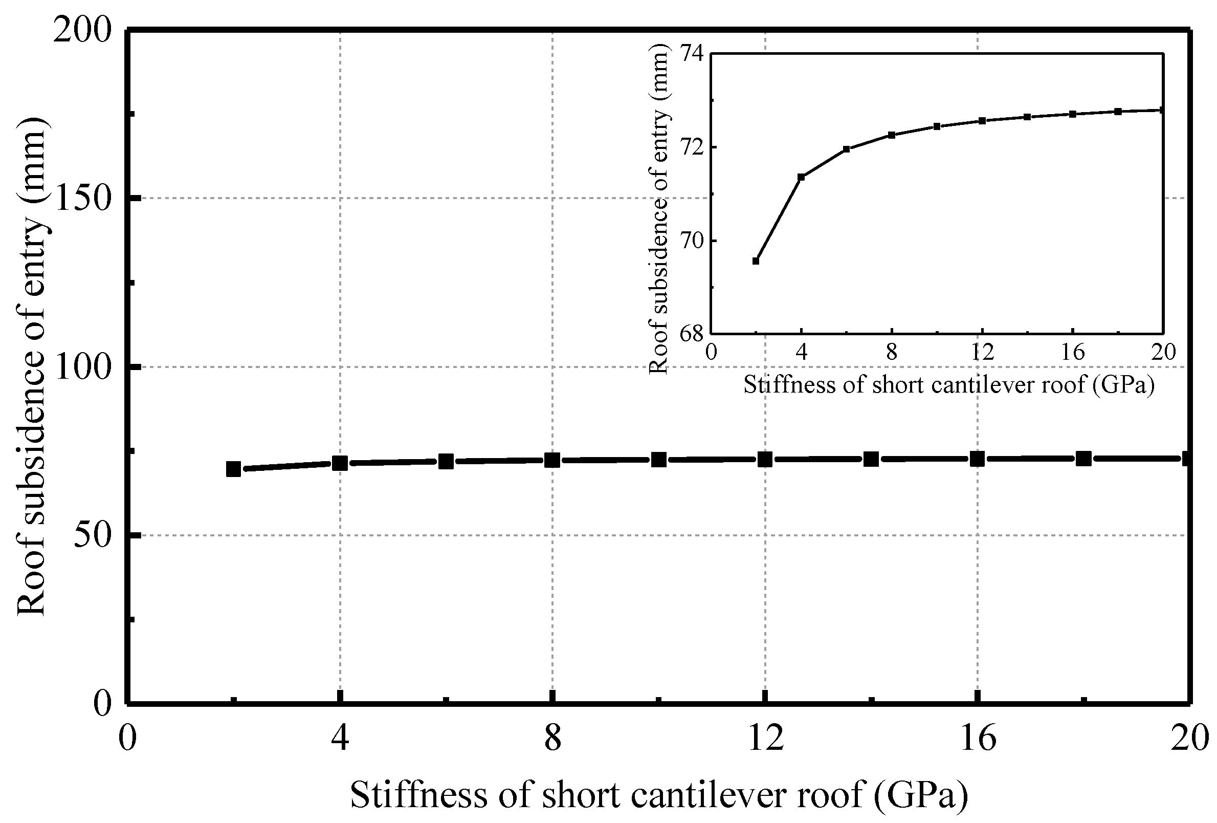
4.2. Relationship between Roof Deformation and Its Stiffness

As in the previous solution, the expression related to roof deformation and its stiffness is shown as Equation (13), and the curve of roof deformation against its stiffness shown in Figure 5 is obtained using Equation (13).
v = 0.008364 E 0.073155
As seen in Figure 5, the roof subsidence of the entry shows little change in the range of 69.56–72.80 mm as the stiffness of the short cantilever roof increases. This indicates that the entry subsidence is slightly affected by its stiffness. It is clear that when the elastic modulus of the roof rock is small, the subsidence value of the short cantilever beam is relatively small. This may be because the strain energy of a given deformation caused by the rotation of the upper main roof (i.e., block B in Figure 2) is absorbed by the short cantilever roof. Then, with increasing elastic modulus, roof subsidence gradually increases and tends to stabilize. This indicates that when the elastic modulus increases and the short cantilever roof gradually transfers to a rigid body, the subsidence of the entry roof surface may be equal to the given deformation caused by rotation of the upper main roof.

4.3. Relationship between Roof Deformation and Its Width

Similar to the solution of Section 3, the expression related to roof deformation of the entry and its width is given in Equation (14), and the curve of roof deformation against its width is shown in Figure 6.
v = 3.312231 a 3 + 0.008663 a 2 + 130.079060 a 0.109045 37.878272 a 2 + 163.279168
According to the design scheme of the Ningtiaota coal mine, the entry width is 6.738 m in order to meet the requirements of production. Thus, as seen in Figure 6, the roof subsidence of entry shows basically linear growth with increasing width. For example, the subsidence value of the entry roof is only 20.67 mm with an entry width of 6.4 m, while it obviously increases to 111.51 mm with a width of 7.0 m. The subsidence increases notably in this range of entry width, which indicates that the subsidence of the entry roof is significantly affected by the entry width. Thus, to guarantee an entry width to meet production, a smaller width of entry should be chosen because of the relatively small subsidence of the entry roof.

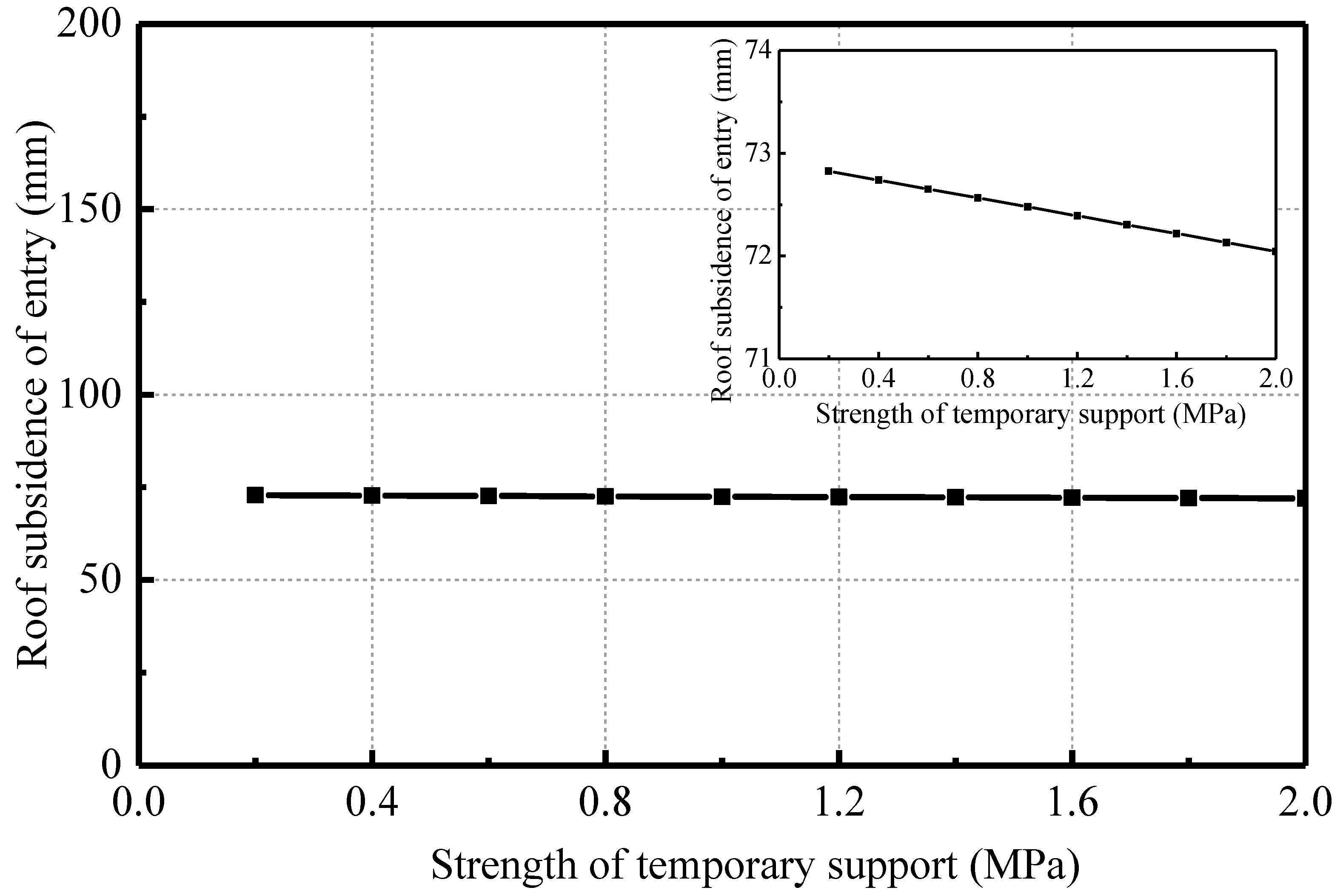
4.4. Relationship between Roof Deformation and Support Strength

Regarding the relationship between roof deformation of the entry and the support strength from a cable or temporary structure, Equations (15) and (16) were calculated with the relative parameters of the Ningtiaota coal mine applied to Equation (8). Then, the curve of roof deformation against the support strength from a bolt and a cable or a temporary structure was obtained using Equations (15) and (16) and is shown in Figure 7 and Figure 8.
v = 0.001096 p z 0.072804 .
v = 0.000433 p l 0.072910 .
In Figure 7 and Figure 8, the roof subsidence of the entry linearly decreases with the increase in the support strength from the bolt and cable or temporary structure; however, the amplitude of the variation is slight. For instance, when the support strength from the cable is 0.1 MPa, the subsidence is 72.69 mm, while it is 71.71 mm with a support strength of 1.0 MPa. The difference in the subsidence between 0.1 MPa and 1.0 MPa can be ignored. Thus, it can be concluded that the effects of the support strength of the bolt and cable or the temporary structure on the roof subsidence are not obvious.
From the analysis of Section 4.1, Section 4.2, Section 4.3, and Section 4.4, we can conclude that the most notable impact factors on the roof subsidence of the gob-side entry are the rotation angle of the upper main roof and the entry width; the stiffness of the short cantilever roof and the strength of the bolt and cable support or temporary support have a slight effect on roof subsidence. Thus, to meet the safety of production, one should choose a smaller width of entry and reduce the rotation of the upper main roof as much as possible.

5. Preventive Countermeasures of Roof Deformations in GERRC

5.1. Control Idea and Countermeasures of Roof Deformation

5.1.1. Overall Control Idea of Roof Deformations

According to the theoretical analysis and field observations in Section 3 and Section 4 and in view of the deformation characteristics of the short cantilever roof and its impact factors, the control ideas and countermeasures for the surrounding rock of the gob-side entry should be considered from two aspects: a reasonable design of roof-cutting height and entry width. A detailed analysis is as follows:
(1) Reasonable design of roof-cutting height
From the aforementioned analysis, it was found that the rotational subsidence and rotation angle of the upper main roof have significant effects on roof deformation of the gob-side entry. Therefore, the control of the upper main roof’s rotational subsidence is the most direct means to controling the deformation of the short cantilever roof. According to the structure of the roof strata shown in Figure 2, we can see that the lower-left corner of block B is the first point to touch the gangue if it turns and subsides. Thus, the maximum subsidence of block B is h − (K − 1)b, calculated using Equation (11) with floor heave not considered.
For the convenience of analysis, we can record the initial broken expansion coefficient of the roof rock that is not compacted as KA. While the roof-cutting height is less than h/(KA − 1), according to Equation (11), the mined-out area cannot be filled with the collapsed gangue even if all the rock within the roof-cutting height caved and a gap between the gangue and upper main roof strata remains. After the fracture of block B, the rock mass produces a significant rotation and subsidence because of the lack of support on the end of the goaf side, and the rotation angle is generally conspicuous. In this state, the strata behaviors of the surrounding rock are drastic and will not weaken unless the end of block B touches the gangue, as shown in Figure 9.
However, according to the strata structure characteristics and Equation (11), the rotary subsidence vr is closely related to the extension height b of the roof cutting. Thus, with a certain mining height and a bulking factor of caved rocks, the rotational subsidence vr decreases as the extension height b of the roof cutting increases. When the extension length b increases to h/(KA − 1), the caved rocks affected by the roof cutting are exactly able to fill the gob and form a bearing structure for the upper main roof, which will reduce the rotational subsidence of the upper main roof, as shown in Figure 10. Thus, to control the roof subsidence of the gob-side entry, the extension height b of the roof cutting should be increased as much as possible and the maximum length should be h/(KA − 1).
Taking the test working face of the Ningtiaota coal mine as an example, the natural bulking coefficient KA of the roof rock is 1.43 according to the geological report. Therefore, if we want the rotational subsidence of the upper main roof vr to be 0, the optimal theoretical roof-cutting height b’ is 8.72 m, calculated using Equation (11). Thus, combined with the calculation result and field test, the roof-cutting length is designed to be 9.0 m and the angle is 10°; thus, the designed roof-cutting height b is 8.86 m and is greater than b’. This means that the roof-cutting height can meet design and security requirements.
(2) Reasonable design of gob-side entry width
The width of the gob-side entry is another important factor that affects the roof deformation of the entry based on the aforementioned analysis. According to the analysis of Section 3 and Section 4.3, the subsidence increases notably as the entry width increases. Thus, to guarantee an entry width that meets production, a smaller entry width should be chosen because of the relatively small subsidence of the entry roof. However, it is worth noting that the entry width is affected by the position of the roof cutting but not by the surface of the gangue wall.
Taking the test working face of the Ningtiaota coal mine as an example, the entry width is designed to be 6.738 m according to the results of the theoretical calculation, ventilation, and transportation requirement sections. However, the actual width generally fluctuates within a range of 6.4–7.0 m because the scraping machine and hydraulic support misregistration are not easily controlled during the production process, as shown in Figure 11.

5.1.2. Control Countermeasures of Roof Deformations

Ningtiaota coal mine is one of the most advanced and efficient mines in China, located in Shaanxi province, China, with an annual capacity of 18 million tons. Figure 12 shows the location and layout of the test panel (i.e., panel S1201-II). The mining depth of the panel S1201-II is 115–170 m and the strike length and dip length of the working face are 2344 m and 280 m, respectively. The main roof of panel S1201-II is medium-grained sandstone with a thickness of 5.4~21.5 m; the immediate roof is siltstone with a thickness of 0.78~4.05 m; the immediate floor is siltstone with a thickness of 1.8~16.3 m, and the main floor is fine-grained sandstone with a thickness of 3.2~19.6 m. As shown in Figure 12, the air return way of panel S1201-II was chosen as the testing entry of the aforementioned new technology. The roadway was formed and retained using the new technology behind the working face of panel S1201-II.
According to the design principle of roof cutting, the roof rock in the cutting range should be fully bulking to fill the mine-out room. According to the actual situation of the site, the mining height near the roadway is 3.75 m and the initial bulking coefficient of the roof rock is 1.43. Thus, the best theoretical cutting height b = 8.72 m can be obtained. Combined with the calculation results and field condition, the length and angle of roof cutting were set at 9.0 m and 10°, respectively. In general, the length of CRLDC should be b + (1.0~2.0 m) and it was designed to be 10.50 m. There were five cables in a row with an interval of 0.80 m, as shown in Figure 13. Row supports were used in the temporary support and were set at the gob side with a size of 1950 × 1200 mm (length × width). The interval of two supports was 2400 mm and the distance between the bracket and laneway’s side was 1.0 m. The support resistance of each bracket was 4000 kN. After the surrounding rocks of the entry stabilized, the supports were gradually withdrawn. The position and detailed parameters of the roof cutting and supports are shown in Figure 13.

5.2. Control Effects of Roof Deformations

As of 25 September 2017, the test working face has been mined 960 m. A series of displacement manual monitoring points of the roof and floor have been arranged at every 10 m of the working face, and the measuring frequency is once a day. Counting the monitoring results in the range of 0–400 m, we obtained the relationship between the roof-to-floor displacement and location, as shown in Figure 14. The blue bar represents the cumulative roof-to-floor deformation and the red bar represents the average deformation rate of recent 30 days in the region of 0–400 m.
According to the red bar in Figure 14, most of the roof-to-floor deformation has been stabilized (i.e., the deformation rate is 0), and only 3 point values are still increasing by a velocity of 0–0.1 mm/d in the range of 0–400 m. According to the blue bar in Figure 14, the maximum cumulative displacement in the region of 0–400 m is 149 mm and the average value is 102 mm. Thus, we can understand that the amount of roof-to-floor deformation is generally small and the stability control effects of the surrounding rock is good using the countermeasures described in Section 5.
Moreover, to further analyze the detailed deformation process of the roof and floor, remote real-time online monitoring of roof-to-floor deformation was carried out using optical fiber sensors (OFS) during the test, and the data were recorded at a frequency of once per hour. The sensors are positioned on the side of the goaf and are 1.0 m from the goaf, as shown in Figure 15.
Nine monitoring points are arranged in the gob-side entry where the measuring point I, which is at the 10 m position in the entry, is the monitoring point with the longest monitoring time currently and of the farthest delayed working face. Its monitoring curve is shown in Figure 16.
Based on the aforementioned monitoring results, the following deformation laws can be obtained:
(1)
Approximately 0–37.4 m behind the working face, there is no significant change in roof-to-floor deformation. This means that the upper main roof has not yet been vigorously moved and the collapse of the shallow roof in the mining area has no obvious effect on the roof of the gob-side entry during this phase. The roadway surrounding rock is in a relatively stable condition.
(2)
Approximately 37.4–141.0 m behind the working face, the value of the roof-to-floor deformation increases rapidly. This indicates that the short cantilever roof is affected significantly by dynamic pressure because of the rotation and sinking of the upper main roof. However, under the action of the temporary support for dynamic pressure bearing, roof deformation is always in the safe range.
(3)
More than 141.0 m behind the working face, the surrounding rock is basically stable, and the value of roof-to-floor deformation no longer increases significantly. It was found that the upper rock mass that had been ruptured touched the gangue and formed a new equilibrium structure during this stage. Thus, the short cantilever roof is in the protective range of the structure and can maintain its own stability under the function of CRLDC. The result of the final stable state is shown in Figure 17.

6. Conclusions

In this study, a novel non-pillar mining technology of gob-side entry retaining formed by roof cutting and pressure release (i.e., GERRC) is introduced. Compared with the traditional mining method, GERRC optimizes roof strata structure by using a roof-cutting technique and reduces the influence of roof collapse on the roadway stability. At the same time, the bulking gangues at the gob are fully used to fill the mine-out room and support the overlying strata, and thus the roof subsidence amount is reduced. The technology has obvious advantages in saving coal resources, reducing tunnel drivage ratio, reducing production cost, and optimizing the stress environment of roadway surroundings. However, GERRC has relatively high requirements on the precision of roof cutting and motion configuration control of the overlying strata.
To explore the deformation characteristics of the roof using this new technology, a mechanical model of a short cantilever beam was established, and the relationship between roof deformations and the main parameters were discussed based on the theoretical model. It can be concluded from the theoretical analysis that the most notable factors that influence roof subsidence of gob-side entry retaining are the rotation angle of the upper main roof and the entry width. However, the stiffness of the short cantilever roof and the strength of the bolt or cable support and temporary support have slight effects on roof subsidence. On this basis, detailed ideas and countermeasures for roof deformation control using the new technique are proposed, including a reasonable design of the roof-cutting height and the gob-side entry width.
Finally, a field test was conducted to verify the reasonability of the proposed countermeasures. Field monitoring indicates that the deformation of the entry roof can be divided into three stages. There was no significant change in roof-to-floor deformation when the monitoring station was 0–37.4 m behind the working face. When the monitoring station was 37.4–141.0 m behind the working face, the roof-to-floor deformation experienced a rapid increase. When the monitoring station was 141.0 m or far behind the working face, there was no significant change in the roof deformation. For a stably retained entry, the maximum cumulative displacement was 149 mm, and the average value was 102 mm. Thus, we can understand that the stability control effects of the surrounding rock are good using the proposed countermeasures. The obtained results can be utilized as a reference for roof deformation control and support the parameter design of this new technology in similar projects.

Acknowledgments

This work is supported by the National Natural Science Foundation of China (No. 51674265) and the State Key Program of National Natural Science Foundation of China (No. 51134005), which are gratefully acknowledged.

Author Contributions

All the authors contributed to this paper. Manchao He conceived and designed the research. Yajun Wang and Yubing Gao performed the theoretical analysis and field tests. Eryu Wang and Jun Yang provided theoretical guidance in the research process.

Conflicts of Interest

The authors declare no conflict of interest.

References

  1. Tan, Y.L.; Yu, F.H.; Ning, J.G.; Zhao, T.B. Design and construction of entry retaining wall along a gob side under hard roof strata. Int. J. Rock Mech. Min. Sci. 2015, 77, 115–121. [Google Scholar]
  2. Yang, H.Y.; Cao, S.G.; Wang, S.Q.; Fan, Y.C.; Wang, S.; Chen, X.Z. Adaptation assessment of gob-side entry retaining based on geological factors. Eng. Geol. 2016, 209, 143–151. [Google Scholar] [CrossRef]
  3. He, M.C.; Zhu, G.L.; Guo, Z.B. Longwall mining “cutting cantilever beam theory” and 110 mining method in China—The third mining science innovation. J. Rock Mech. Geotech. Eng. 2015, 7, 483–492. [Google Scholar] [CrossRef]
  4. Tao, Z.G.; Song, Z.G.; He, M.C.; Meng, Z.G.; Pang, S.H. Principles of the roof cut short-arm beam mining method (110 method) and its mining-induced stress distribution. Int. J. Min. Sci. Technol. 2017. [Google Scholar] [CrossRef]
  5. Deng, Y.H.; Wang, S.Q. Feasibility analysis of gob-side entry retaining on a working face in a steep coal seam. Int. J. Min. Sci. Technol. 2014, 24, 499–503. [Google Scholar] [CrossRef]
  6. Zhang, Y.Q.; Tang, J.X.; Xiao, D.Q.; Sun, L.L.; Zhang, W.Z. Spontaneous caving and gob-side entry retaining of thin seam with large inclined angle. Int. J. Min. Sci. Technol. 2014, 24, 441–445. [Google Scholar] [CrossRef]
  7. Li, S.; Li, J.W.; Fan, C.J.; Luo, M.K.; Han, Y.L. Roof subsidence laws and control technology for gob-side entry retaining in fully-mechanized top-coal caving face. J. China Coal Soc. 2015, 40, 1989–1994. [Google Scholar]
  8. Wang, W.J.; Hou, C.J.; Bai, J.B.; Zhang, X.M. Mechanical deformation analysis of the roof coal of road driving along next goaf in sublevel caving face. Chin. J. Geotech. Eng. 2001, 23, 209–211. [Google Scholar]
  9. Gao, F.; Qian, M.G.; Miao, X.X. Mechanical analysis of the immediate roof subjected to given deformation of the main roof. Chin. J. Rock Mech. Eng. 2000, 19, 145–148. [Google Scholar]
  10. Lu, X.Y.; Hua, X.Z.; Zhao, M.Q. Calculation and analysis of immediate roof subsidence in gob-side entry retaining. J. Min. Saf. Eng. 2011, 28, 34–38. [Google Scholar]
  11. Ma, Z.G.; Gong, P.; Fan, J.Q.; Geng, M.M.; Zhang, G.W. Coupling mechanism of roof and supporting wall in gob-side entry retaining in fully-mechanized mining with gangue backfilling. Min. Sci. Technol. 2011, 21, 829–833. [Google Scholar] [CrossRef]
  12. Feng, X.W.; Zhang, N. Position-optimization on retained entry and backfilling wall in gob-side entry retaining techniques. Int. J. Coal Sci. Technol. 2015, 2, 186–195. [Google Scholar] [CrossRef]
  13. Zhang, N.; Yuan, L.; Han, C.L.; Xue, J.H.; Kan, J.G. Stability and deformation of surrounding rock in pillarless gob-side entry retaining. Saf. Sci. 2012, 50, 593–599. [Google Scholar] [CrossRef]
  14. Han, C.N.; Zhang, N.; Li, B.Y.; Si, G.Y.; Zheng, X.G. Pressure relief and structure stability mechanism of hard roof for gob-side entry retaining. J. Cent. South Univ. Technol. 2015, 22, 4445–4455. [Google Scholar] [CrossRef]
  15. Yang, D.W.; Ma, Z.G.; Qi, F.Z.; Gong, P.; Liu, D.P.; Zhao, G.Z.; Zhang, R.R. Optimization study on roof break direction of gob-side entry retaining by roof break and filling in thick-layer soft rock layer. Geomech. Eng. 2017, 13, 195–215. [Google Scholar]
  16. Kan, J.G.; Zhang, N.; Wu, J.K.; Wu, H. Effect of main roofs fracture position on the secondary gob-side entry retaining stability. Disaster Adv. 2013, 6, 189–199. [Google Scholar]
  17. Li, X.H.; Ju, M.H.; Yao, Q.L.; Zhou, J.; Chong, Z.H. Numerical investigation of the effect of the location of critical rock block fracture on crack evolution in a gob-side filling wall. Rock Mech. Rock Eng. 2016, 49, 1041–1058. [Google Scholar] [CrossRef]
  18. Ning, J.G.; Wang, J.; Liu, X.S.; Qian, K.; Sun, B. Soft-strong supporting mechanism of gob-side entry retaining in deep coal seams threatened by rockburst. Int. J. Min. Sci. Technol. 2014, 24, 805–810. [Google Scholar] [CrossRef]
  19. Wang, H.S.; Zhang, D.S.; Liu, L.; Guo, W.B.; Fan, G.W.; Song, K.; Wang, X.F. Stabilization of gob-side entry with an artificial side for sustaining mining work. Sustainability 2016, 8, 627. [Google Scholar] [CrossRef]
  20. Gao, Y.B.; Liu, D.Q.; Zhang, X.Y.; He, M.C. Analysis and optimization of entry stability in underground longwall mining. Sustainability 2017, 9, 2079. [Google Scholar] [CrossRef]
  21. He, M.C.; Gao, Y.B.; Yang, J.; Gong, W.L. An innovative approach for gob-side entry retaining in thick coal seam longwall mining. Energies 2017, 10, 1785. [Google Scholar] [CrossRef]
  22. Gao, Y.B.; Guo, Z.B.; Yang, J.; Wang, J.W.; Wang, Y.J. Steady analysis of gob-side entry retaining formed by roof fracturing and control techniques by optimizing mine pressure. J. China Coal Soc. 2017, 42, 1672–1681. [Google Scholar]
  23. He, M.C.; Gao, Y.B.; Yang, J.; Guo, Z.B.; Wang, E.Y.; Wang, Y.J. An energy-gathered roof cutting technique in no-pillar mining and its impact on stress variation in surrounding rocks. Chin. J. Rock Mech. Eng. 2017, 36, 1314–1325. [Google Scholar]
  24. Qian, M.G. A structural model of overlying strata in longwall workings and its application. J. China Univ. Min. Technol. 1982, 11, 1–11. [Google Scholar]
  25. Song, Z.Q. The basic regulation of overlying strata in longwall workings. J. Shandong Univ. Sci. Technol. 1979, 1, 67–80. [Google Scholar]
  26. Xu, Z.L. Elasticity; Higher Education Press: Beijing, China, 2006; pp. 257–271. [Google Scholar]
  27. Wang, P.; Jiang, L.S.; Jiang, J.Q.; Zheng, P.; Li, W. Strata Behaviors and Rock Burst-Inducing Mechanism under the Coupling Effect of a Hard, Thick Stratum and a Normal Fault. Int. J. Geomech. 2018, 18, 04017135. [Google Scholar] [CrossRef]
  28. Su, C.D.; Gu, M.; Tang, X.; Guo, W.B. Experiment study of compaction characteristics of crushed stones from coal seam roof. Chin. J. Rock Mech. Eng. 2012, 31, 18–26. [Google Scholar]
  29. Li, Y.F.; Hua, X.Z. Mechanical analysis of stability of key blocks of overlying strata for gob-side entry retaining and calculating width of roadside backfill. Rock Soil Mech. 2012, 33, 1134–1140. [Google Scholar]
Figure 1. Schematic diagram of the roadway layout.
Energies 11 00627 g001
Figure 2. Schematic diagram of the entry surrounding structure.
Energies 11 00627 g002
Figure 3. Mechanical model of the short cantilever beam.
Energies 11 00627 g003
Figure 4. Relationship between roof subsidence and the rotational angle of key blocks.
Energies 11 00627 g004
Figure 5. Relationship between roof subsidence and its stiffness.
Energies 11 00627 g005
Figure 6. Relationship between roof subsidence and the width of the gob-side entry.
Energies 11 00627 g006
Figure 7. Relationship between roof deformation and bolt and cable support strength.
Energies 11 00627 g007
Figure 8. Relationship between roof subsidence and temporary support strength.
Energies 11 00627 g008
Figure 9. Roof structure and motion state when the roof-cutting height is insufficient. (a) Initial state; (b) Terminal state.
Energies 11 00627 g009
Figure 10. Roof structure and motion state when the roof-cutting height is sufficient. (a) Initial state; (b) Terminal state.
Energies 11 00627 g010
Figure 11. Statistical diagram of the retaining roadway width.
Energies 11 00627 g011
Figure 12. Layout of S1201-II working face and gateroads.
Energies 11 00627 g012
Figure 13. Roof-cutting and support parameters for the retained entry.
Energies 11 00627 g013
Figure 14. Roof-to-floor displacement monitoring results.
Energies 11 00627 g014
Figure 15. Installation of optical fiber sensors.
Energies 11 00627 g015
Figure 16. Roof-to-floor displacement monitoring results.
Energies 11 00627 g016
Figure 17. Final entry retaining effects. (a) Before temporary support is withdrawn; (b) Temporary support has been withdrawn.
Energies 11 00627 g017

