Virtual Inertia Control Application to Enhance Frequency Stability of Interconnected Power Systems with High Renewable Energy Penetration


Department of Electrical and Electronic Engineering, Kyushu Institute of Technology, Tobata-ku, Kitakyushu-shi, Fukuoka 804-8550, Japan
*
Author to whom correspondence should be addressed.
Energies 2018, 11(4), 981; https://doi.org/10.3390/en11040981
Submission received: 26 January 2018
/
Revised: 5 April 2018
/
Accepted: 17 April 2018
/
Published: 18 April 2018
Abstract
:Due to a rapid increase in the utilization of power converter-based renewable energy sources (RESs), the overall system inertia in an interconnected power system might be significantly reduced, increasing the vulnerability of the interconnected power system to the system instability. To overcome problems caused by the significant reduction in system inertia, this paper proposes a new application of virtual inertia control to improve frequency stability of the interconnected power system due to high penetration level of RESs. The derivative control technique is introduced for higher-level applications of virtual inertia emulation. Thus, the proposed virtual inertia control loop has a second-order characteristic, which provides a simultaneous enabling of damping and inertia emulations into the interconnected power system, enhancing frequency stability and resiliency. System modeling and simulation results are carried out using MATLAB/Simulink® (R2016b, MathWorks, Natick, MA, USA). Trajectory sensitivities are also performed to analyze the dynamic effects of virtual inertia control’s parameters on the system stability. The effectiveness of the virtual inertia control concept on stability improvement is verified through a multi-area test system with high RESs penetration level for different contingencies.
1. Introduction
The transition to a low carbon community is the driving force pushing conventional power systems to increase the number of renewable energy sources (RESs), which mainly apply power converters as an interface to the power-grid. Consequently, the integration of RESs is the main challenge for the electrical industry and grid-connected RESs [1,2]. The penetration of various RESs in modern interconnected power systems may cause a significant reduction in system inertia. As RESs transfer power to a multi-area power system using converters/inverters, such power electronic interfaces will decrease the total system inertia and lower the voltage/frequency stabilization compared to conventional synchronous generating units. Thus, a reduction of sufficient inertia will be one of the major limitations of the grid-connected RESs worldwide. By increasing RESs penetration presently, the inertia of the interconnected power system might be insufficient, creating dynamic issues to stabilize system voltage and frequency, and causing negative impacts on power system stability/resiliency [3,4].
In conventional interconnected power systems, the rotational inertia of synchronous generations plays an important role, which has the finest abilities, such as a larger moment of inertia and larger output impedance. Conventional interconnected power systems maintain stability in disturbances due to their high inertia and control of synchronous generators. Hence, power system stability (e.g., voltage/frequency) is stabilized and well regulated. Currently, the enhancing penetration of converter-based generators causes a major reduction of system inertia and stabilization. In order to overcome the problem introduced by power electronic-based RESs, one of the recent solutions is to imitate the synchronous generator behavior virtually in the power system, enhancing system inertia and stability [5]. It is called a virtual synchronous generator (VSG), which imitates the important behavior of prime movers (e.g., inertia characteristic) and synchronous machines, as well as providing ancillary service to the system [6,7]. Implementing virtual inertia control, the action of the prime mover is imitated for frequency control support. The method is applied based on the rate of change of frequency, calculating frequency deviations to give additional active power to the set-point. Thus, this method imitates the inertia characteristic of the synchronous generator, which can contribute to the overall inertia of power system, improving frequency performance and stability.
Recently, considerable research has been proposed regarding virtual inertia control designs [5,6,7,8,9,10,11,12,13,14]. Reference [8] compared the dynamic characteristics of VSG and droop control methods to imitate inertia in the power system. Reference [9] applied a droop control technique to perform synthetic inertia as an alternative inertia response in wind turbine systems for improving the dynamic stability. Reference [10] designed the control method to substitute today’s inherent inertia in European power system. Reference [11] proposed the integration of DC microgrids as virtual synchronous machines into the power system/utility grid. Reference [12] proposed model predictive control technique-based virtual inertia control to improve the stability performances of microgrids. Almost 100% of grid-connected renewable energy systems [13] have proposed the robust virtual inertia control as a means to support the frequency stability of microgrids. Reference [14] presents the robust tuning methods to select optimum parameters of virtual inertia control for the power system. From previous references, the effects of transmission systems have not been considered for virtual inertia control. In fact, most research has focused on the analysis of virtual inertia control in a single-area power system, such as a microgrid (e.g., small-scale power system). No report focuses on virtual inertia control for transmission and high voltage alternating current (HVAC) parts of interconnected power systems (e.g., large-scale power system). Focusing on multi-area power systems with an increase of RESs penetration, applications of interconnected power systems are widely increased to exchange power and strengthen stability and reliability. In [15,16,17,18], superconducting magnetic energy storage (SMES) systems and HVAC/HVDC parallel tie-lines have been designed and studied for a different type of interconnected power systems. Based on the aforementioned references, there is no report for inertia control methods to analyze the effects of inertia during high RESs penetration and contingencies. The generic modeling of interconnected power systems is designed and presented in [19,20,21,22], but it does not provide enough details about modeling virtual inertia control for HVAC parts or transmission lines in a large scale power system. Nevertheless, the utilization of the virtual inertia control in securing ancillary services for enhancing frequency performance of interconnected systems is also another motivation for this work.
Considering these issues, this paper presents a new application of virtual inertia control to improve frequency stability of interconnected power systems. The virtual inertia control system using converter-based components will be applied to an interconnected power system, improving system inertia and avoiding instability and collapse during RESs penetration and contingencies. Hence, the general model of a multi-area power system will be modified by adding the virtual inertia control loop-based derivative control method, for higher-level frequency control studies. The main objective of this work is to propose a novel control technique of frequency stability analysis-based inertia control domain for multi-area power systems owing to high-level RESs integration. Consequently, the proposed virtual inertia control can effectively contribute to a better exploitation of RESs in the interconnected power systems, while maintaining the robustness of system operation. The main contribution of this work is to propose a useful model for the pre-evaluation of dynamic effects of a multi-area power system, including virtual inertia control system based on advanced level control design for power system applications. Ultimately, the proposed virtual inertia control can improve and maintain the frequency stability of the interconnected power system and mainly when the RESs are highly penetrated at partial load. Compared to [19], the interconnected power system with virtual inertia control will provide better stability and performance for the power systems of today, and for those of the future, which are expected to integrate more and more renewable energy; thus, the proposed technology will ensure an avoidance of power system instability and system collapse.
The rest of this paper is presented as follows: a brief introduction on frequency control relating to inertia power and the modeling of the two-area test system is given in Section 2; in Section 3, the virtual inertia control design-based derivative control technique is proposed for interconnected power systems; simulation results are provided in Section 4; and finally, some conclusions are outlined in Section 5.
2. Dynamic Modeling of Multi-Area Power System
2.1. Structure of Inertia Control
System inertia (H) is the primary source of electrical system robustness regarding frequency control; this arises due to an imbalance in load demand and generation. The conventional, large synchronous generators directly connected to the grid are the main source of inertia. They play an important role in limiting the rate of change of frequency (ROCOF), and provide a natural response to the system frequency variations following contingencies such as an unscheduled loss of generation or load in the power system. Generally, frequency control can be divided into three main processes: the inertia control process, the primary control process, and the secondary control process. During inertia control, the controllers are not activated and the requirement of power is compensated by kinetic energy from the synchronous generation units during frequency deviation. During primary control, the controller stabilizes system frequency to the new steady-state for 10 to 30 s after the contingency. Lastly, during secondary control (i.e., Load Frequency Control (LFC)), the controller recuperates system frequency to its equilibrium stage for 30 s to 30 min after the contingencies [19,23].
In traditional system-based synchronous generators, the inertia response is calculated by kinetic energy. The overall kinetic energy (Ekinetic) of system rotational mass, and the spinning loads, can be obtained as [23]:
where J denotes the moment of the system inertia (kgm2), and ω the rotor speed (rad/s).
The rate of change of rotor speed is effected by the torque balance of the spinning mass as [23]:
where Te and Tm represent the electrical and mechanical torque respectively. Pe and Pm represent the electrical and mechanical power respectively.
The kinetic energy (Ekinetic) stored in the system is usually characterized as a proportion of its power rating, and is labeled as a constant of system inertia (H), as follows [19,23]:
where S is the system rated power (VA).
It is known that the rate of change of frequency (ROCOF) relies on system inertia and initial power mismatch [19,23]. Therefore, ROCOF is computed as follows:
The ROCOF can be represented in form of per unit (p.u.) as follows:
where dω/dt is the initial ROCOF. Pe and Pm denote the electrical and mechanical power respectively. H denotes the inertia constant of the entire system after the disturbance; S is the system rated power.
Considering (5), it indicates that the system is considered as a single power system, producing the total system inertia with a single system frequency and ROCOF. The magnitude of the power imbalance caused by the disturbance determines how rapidly the system frequency and generator’s speed changes. Thus, this is termed the ROCOF.
2.2. Structure of Frequency Control
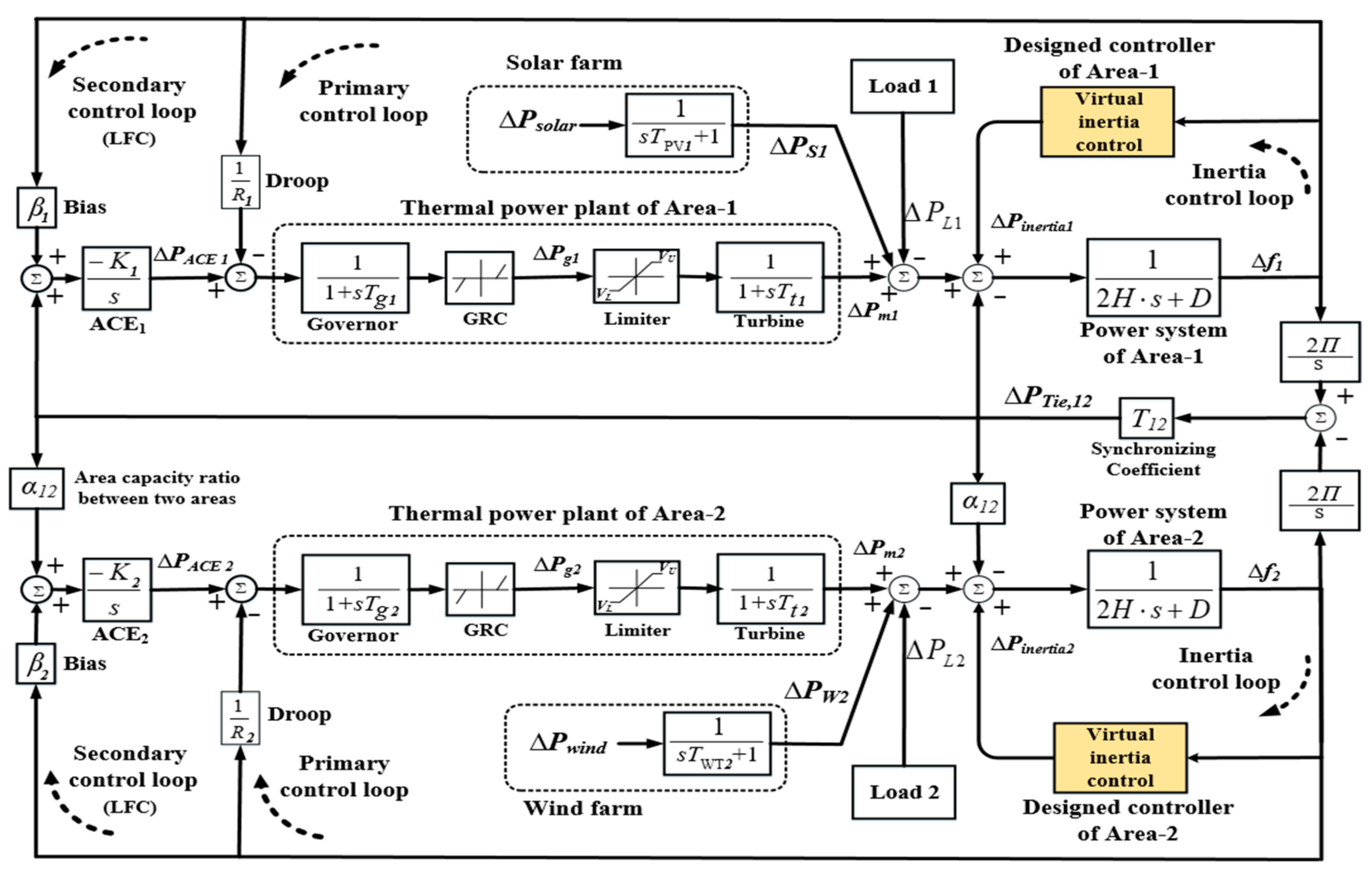
The interconnected power system with high RESs penetration employed in this research is shown in Figure 1. The studied system comprises two areas that are interconnected by a high-voltage alternating current transmission line (HVAC) or tie line. Due to high RESs penetration (e.g., wind/solar generations) in the modern interconnected power system, these RESs-based electronic interfaces may possess a low moment of inertia, and an absence of frequency stabilization in such a system. Virtual inertia control is expected to additionally compensate for any real-power unbalance in the interconnected system incorporating with the LFC, or when the LFC is not available.
A low-order linearized model can be used to design the load-generation dynamic behavior of the interconnected system. The linearized model is shown in Figure 2. The system parameters are shown in Figure 1 and Table 1. In order to obtain the accurate behavior of the typical interconnected power system, this paper considers the significant constraints from the physical dynamics of the load and generation units, including inherent conditions. The important physical constraint of the thermal generation unit is the rate of change of power generation owing to the thermal/mechanical movement limitations. The physical dynamics of the thermal power plant can be represented by the minimum and maximum valve gate opening/closing for the turbine system, and the generation rate constraint (GRC). The VL and VU are the minimum and maximum limits, which control the rate of the valve-gate closing/opening speed of the turbine system [19]. The generation rate constraint of the non-reheat thermal power plant is set at 12% p.u. MW/min. This work assumed that the generation units of the same characteristic are presented via the aggregated model. Wind/solar power generations and domestic loads are considered as disturbances to the interconnected power system. The RESs in some systems might have a high-order dynamic response. However, the low-order dynamic models applied in this work are appropriate for investigating frequency control issues [19,24,25]. Therefore, the frequency deviation of the interconnected power system without virtual inertia control system for the i-th area can be calculated as follows:
where,
where ∆Pmi is the power generated by the thermal generation in the area-i. ∆Pgi is the power generated by the turbine system in the area-i. ∆PWi is the generated power from the wind farm in the area-i, and ∆PSi is the generated power from the solar farm in the area-i.
The area control error (ACE) is determined as the linear combination of the weighted frequency deviation and tie-line power flow as shown below [19]. All of the parameters explained in (7)–(11), and their values, are shown in Table 1.
To design the interconnections between N areas in an interconnected power system, the tie-line power variation between the area-i and the rest of the areas can be calculated as [19,23]:
where Tij is the synchronizing coefficient between areas, ∆PTie,ij is the tie-line power exchange between the area-i and the area-j, and Pri, Prj are the rated power in the area-i and the area-j, respectively.
3. Virtual Inertia Control Design Based on Derivative Control Technique
3.1. Concept of Virtual Inertia Control
The transition to a low carbon community is the driving force pushing the conventional power system to increase the volume of non-synchronous generators (e.g., renewable energy sources), which mainly apply power convertors for the interface to the grid-network. These power converter interfaces can decrease the system inertia (H), and give a lower frequency stabilization effect compared to the conventional system-based synchronous generators. To overcome such a problem, the concept of virtual inertia control is implemented. Implementing virtual inertia control, the action of the prime mover is imitated to enhance system inertia and frequency stability [7,8]. If active power via power electronic converters of energy storage systems (ESS) is proportionally controlled by the derivative of the system frequency, the virtual inertia power can be virtually imitated, which contributes to improving the inertial response of the system against the variations in RESs penetration and power demand. The control law for active power-based converter can be calculated as [14,26,27]:
where kc indicates the converter gain-based proportional conversion. f0 denotes the grid nominal frequency, and PEmulate the emulated power.
3.2. Proposed Model of Multi-Area Power System with Virtual Inertia Control
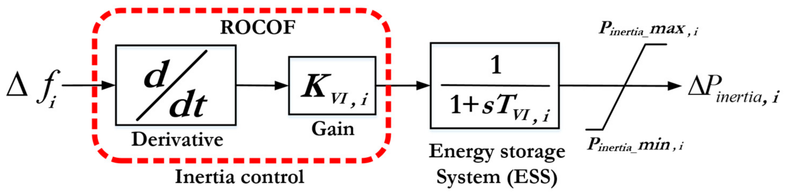
In order to create sufficient virtual inertia-based power electronic converters, the dynamic structure and control is demonstrated in Figure 3. The derivative control technique is the main concept of the virtual inertia control that can calculate the rate of change of frequency (ROCOF) to modify an additional power to a set point of the area-i during RESs penetration and contingency [14,23]. However, the derivative control technique is very sensitive to the noise of frequency measurements. To overcome this challenge, a low pass filter is applied to control the system. Moreover, the low-pass filter can provide dynamic behaviors of the ESS. Accordingly, virtual inertia control can contribute to the interconnected power system as if the RESs in such a system would have inertia power similar to that of conventional power system-based synchronous generators. Therefore, the proposed virtual inertia control creates the inertia characteristic, providing to the overall inertia of the interconnected power system, improving the frequency performance and stability. In this work, we assumed that virtual inertia power could be created by the ESS in both areas.
The control law for emulating inertia power in the domain of Laplace based on per-unit system is displayed in Figure 3. During the deviation of frequency, the proposed virtual inertial control will deliver the desired power to the i-th area, as follows [12,13,14,27]:
where TVI, i indicates the time constant-based virtual inertia for imitating the dynamic control of ESS in the area-i, and KVII,i indicates the virtual inertia control gain in the area-i. For a per-unit system, ∆ω has the same value as ∆f and ∆fi is the frequency deviation in the area-i.
Finally, the proposed inertia control system using derivative control technique will calculate ROCOF; the virtual inertia gain (KVI) will modify the active power reference of the ESS for emulating the inertia power. Consequently, adding virtual inertia (i.e., emulated power) modifies (6) to (17), representing the dynamic model of a multi-area system with virtual inertia control. The frequency deviation for the area-i must be calculated by considering the generation/load power signals, inertia power signals, and tie-line power signals as follow:
where ∆fi is the frequency deviation in the area-i. Hi is the constant of inertia in the area-i, and ∆Pmi is the generated power from the thermal generation unit in the area-i. Di is the damping coefficient in the area-i. ∆PWi is the generated power from the wind farm in the area-i. ∆PSi is the generated power from the solar farm in the area-i. ∆Pinertia,i is the emulated inertia power from ESS unit in the area-i. ∆PLi is the load changes in the area-i. ∆PTie,i is the overall tie-line AC power changes from the area-i.
4. Simulation Results and Discussions
This section discusses the simulation results of the proposed control technique. The simulation studies are performed in the MATLAB/Simulink® software with all the details of the components (See Figure 1 and Table 1) under high-level operations of primary and secondary controls in the system. The results and discussion are divided into two sections: the first discusses the effects of virtual inertia control gains, including inertia itself, on the performance of the interconnected system; the second discusses the dynamic effects of frequency response of the system with virtual inertia control under severe test contingencies. Since the simulation and analysis of the interconnected system in this study (See Figure 2) are performed in per-unit system, the proposed control method can be easily applied to larger power systems, and the selection of the system base in Table 1 does not affect the simulation results.
4.1. Eigenvalue Analysis of Virtual Inertia Control
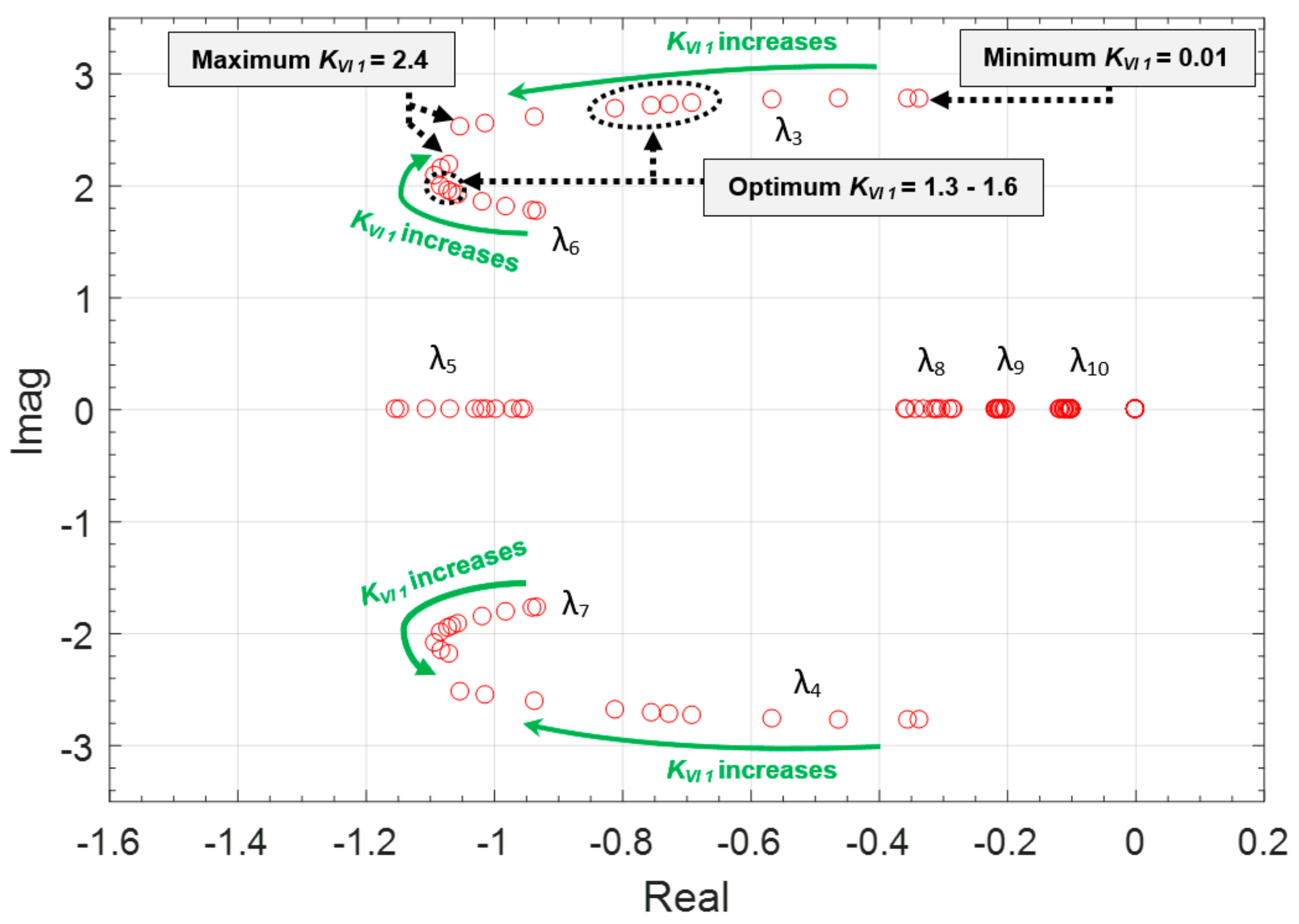
The dynamic effects of virtual inertia using derivative control technique are analyzed for interconnected power systems. In this section, the main objective is to investigate the significant effect of virtual inertia control gains (i.e., KVI1, KVI2) on the stability and performance of the system. Therefore, the eigenvalue trajectory of the interconnected power system is determined for a wide range of parameter changes of KVI1 and KVI2.
The effect of various changes on the virtual inertia control gain in Area-1 (KVI1) is analyzed and observed in Figure 4. After increasing the control gain KVI1, the system approaches better stability due to the negative real part of most eigenvalues situated far away in the left side of the s-plane (See Figure 4). Clearly, applying virtual inertia control to the interconnected power system can significantly enhance the system dynamic performance, by moving the eigenvalues to a better region in the left-half side of the s-plane. On the other hand, if the control gain KVI1 is increased too much, the 6th mode (λ6) and 7th mode (λ7) will have negative impacts on the system performance by moving back to the right side of the s-plane, causing the system to move to a less stable and more oscillatory region. Thus, based on the trajectory in Figure 4, the optimum values of KVI1, which could not deteriorate the dynamic stability, are determined in the range of 1.3–1.6.
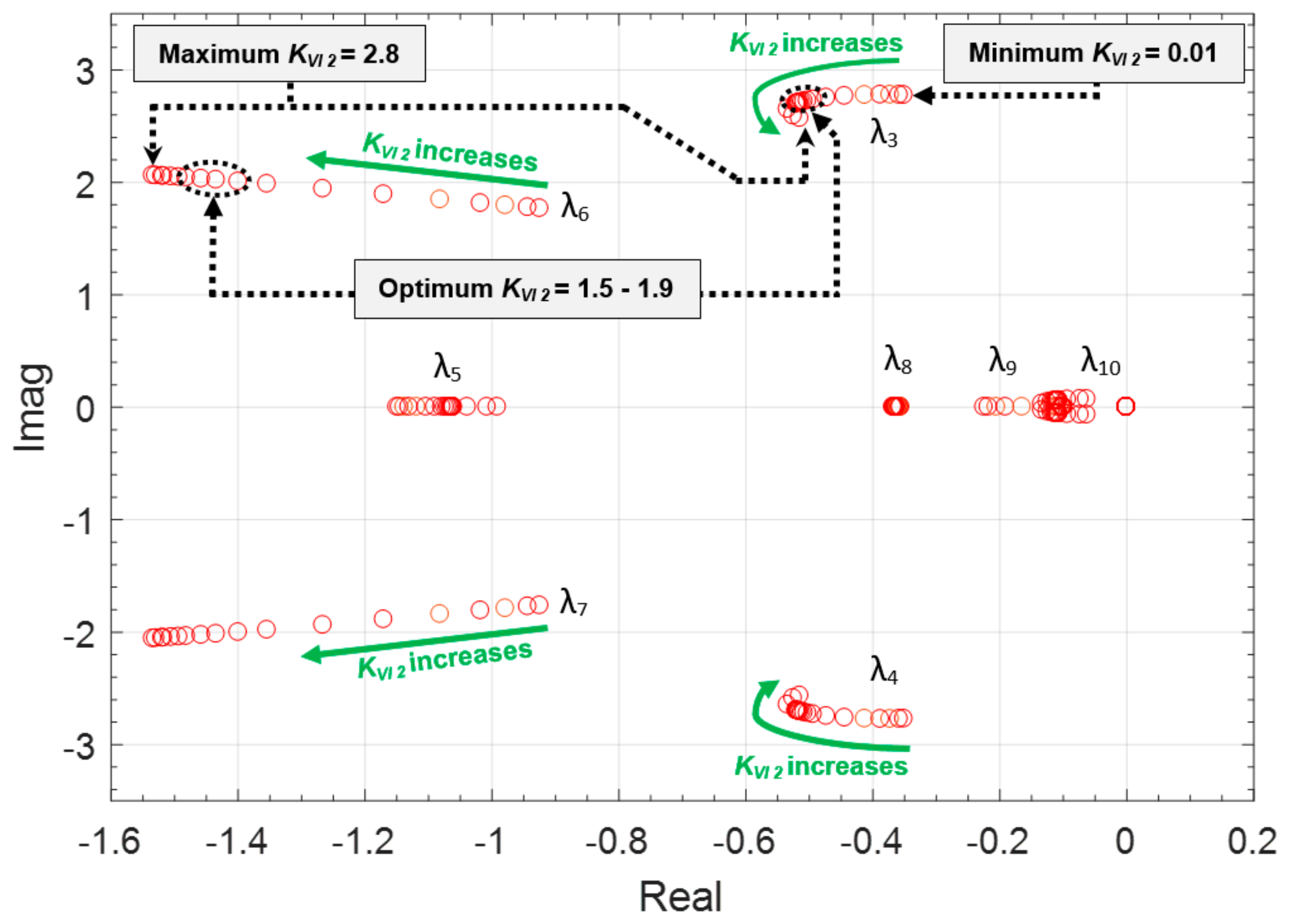
Similarly, the effect of numerous changes on the virtual inertia control gain in Area-2 (KVI2) is investigated and presented in Figure 5. The results indicate that by increasing the control gain KVI2, the system can obtain more stability and less oscillation because most of the eigenvalues move far away to the left side of the s-plane. In contrast, by applying a higher control gain of KVI2, it is obvious that various modes (i.e., λ3, λ4) will approach the right of the s-plane, which can deteriorate the dynamic stability and performance of the interconnected power system. Analyzing the trajectory in Figure 5, the optimum values of KVI2, which could not deteriorate the system stability, are evaluated in the range of 1.5–1.9. Therefore, it is summarized that the optimum selection of the virtual inertia control gain is a tradeoff for obtaining the most optimal response from the interconnected power system during these contingencies.
4.2. Abrupt Load Change
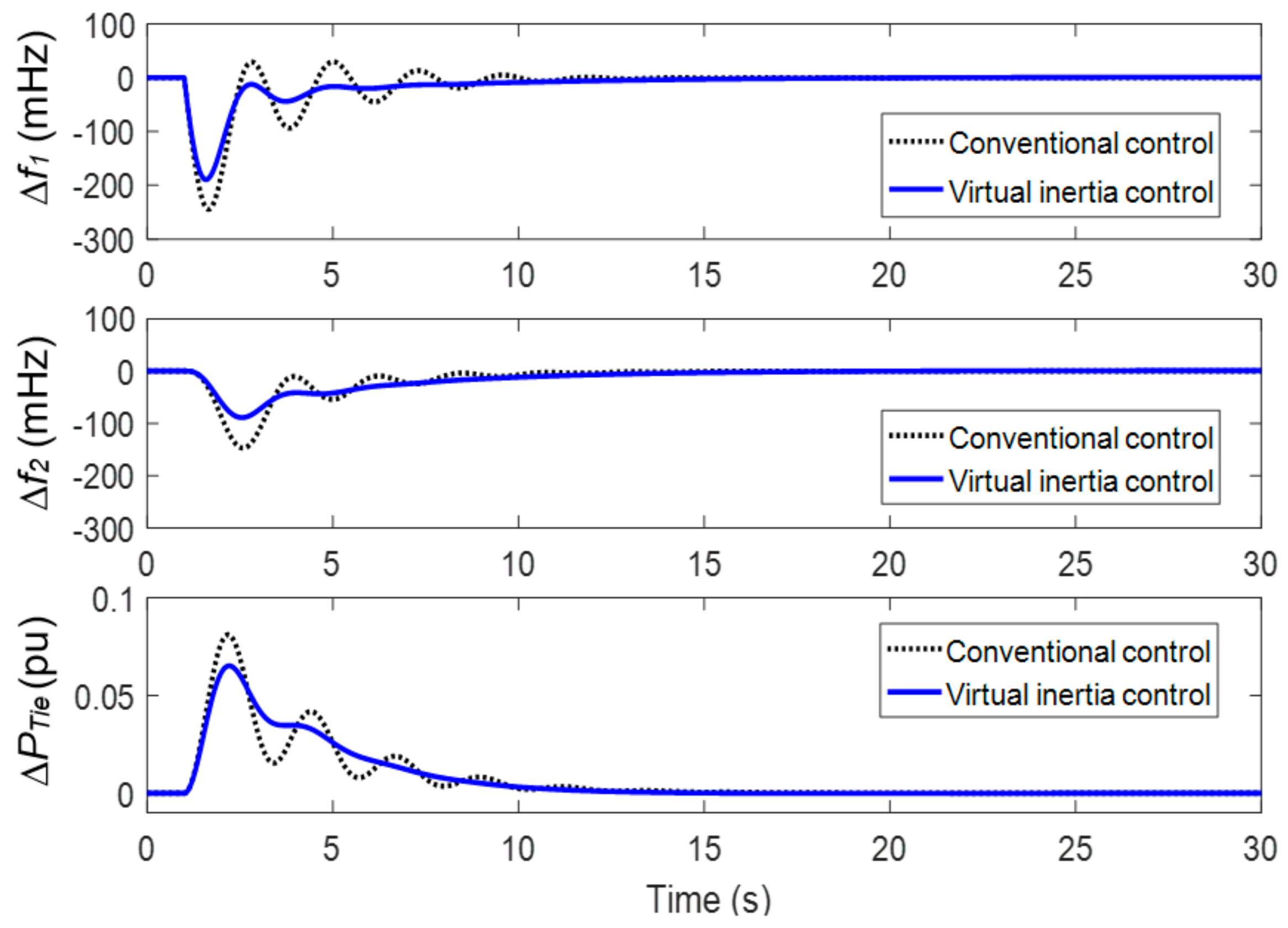
In this case study, the interconnected power system has been considered as a test system to demonstrate the efficiency of the control method. The proposed control technique has been examined by using a 1.5 MW step load change (∆PL = 0.1 p.u.) in Area-1. To evaluate the efficiency of the proposed control technique, this is compared with the high-level operations of primary and secondary controls, known as the conventional control [19,20,21,22].
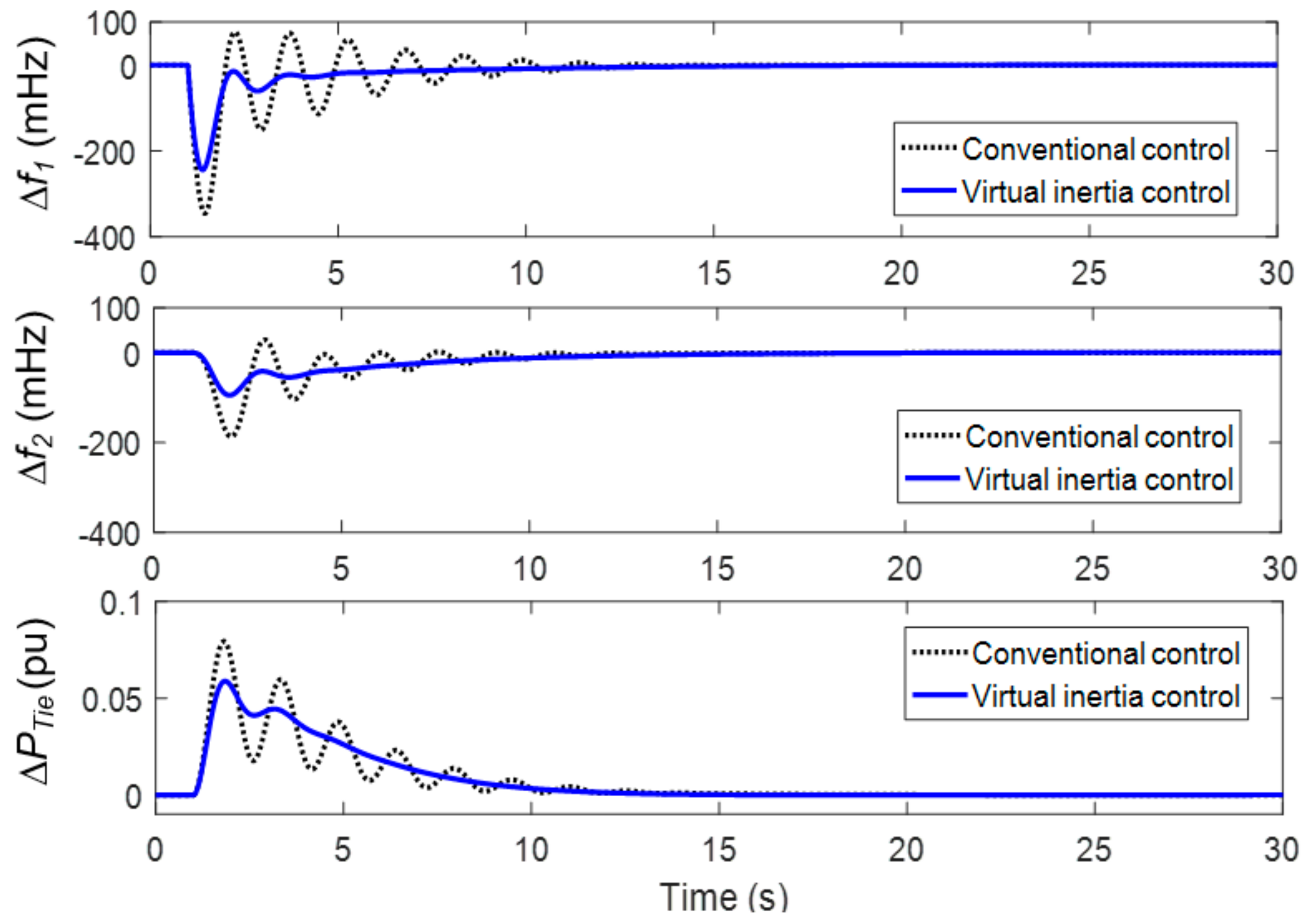
Figure 6 and Figure 7 display the system response in the circumstances of normal and low system inertia (reduced 50% from its initial values in each area). The results from the top to the bottom are: frequency deviation in Area-1, frequency deviation in Area-2, and tie-line power change. In situations of either normal or low inertia, the system with virtual inertia control is more stable and faster, compared to that with conventional control. Clearly, the virtual inertia control (solid line) significantly enhances frequency performance and decreases the magnitude of system transients, compared to the studied system with no virtual inertia control (dotted line). Moreover, the transient frequency stability and tie-line power flow are obviously enhanced when the interconnected power system is employed with the proposed virtual inertia control.
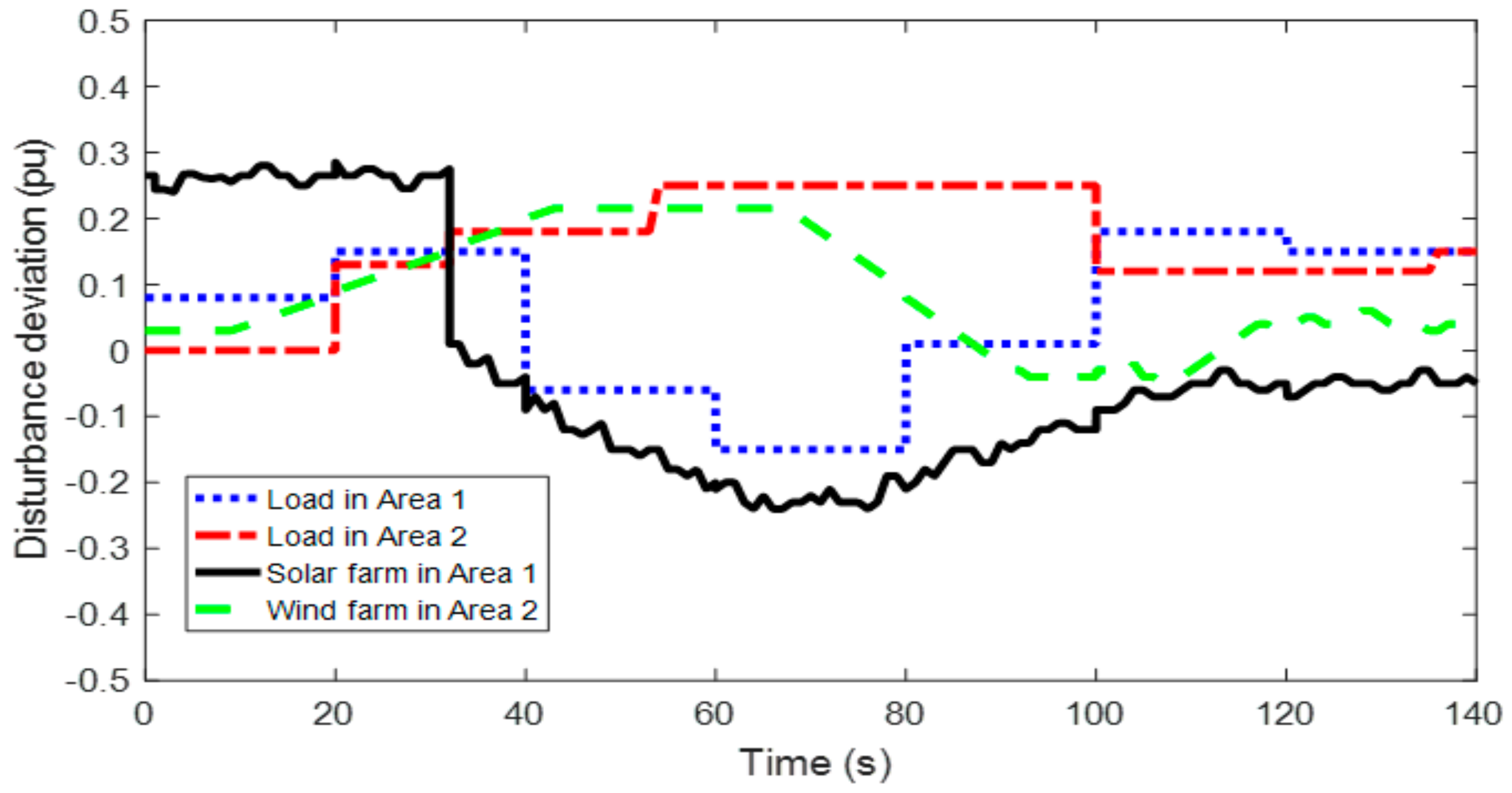
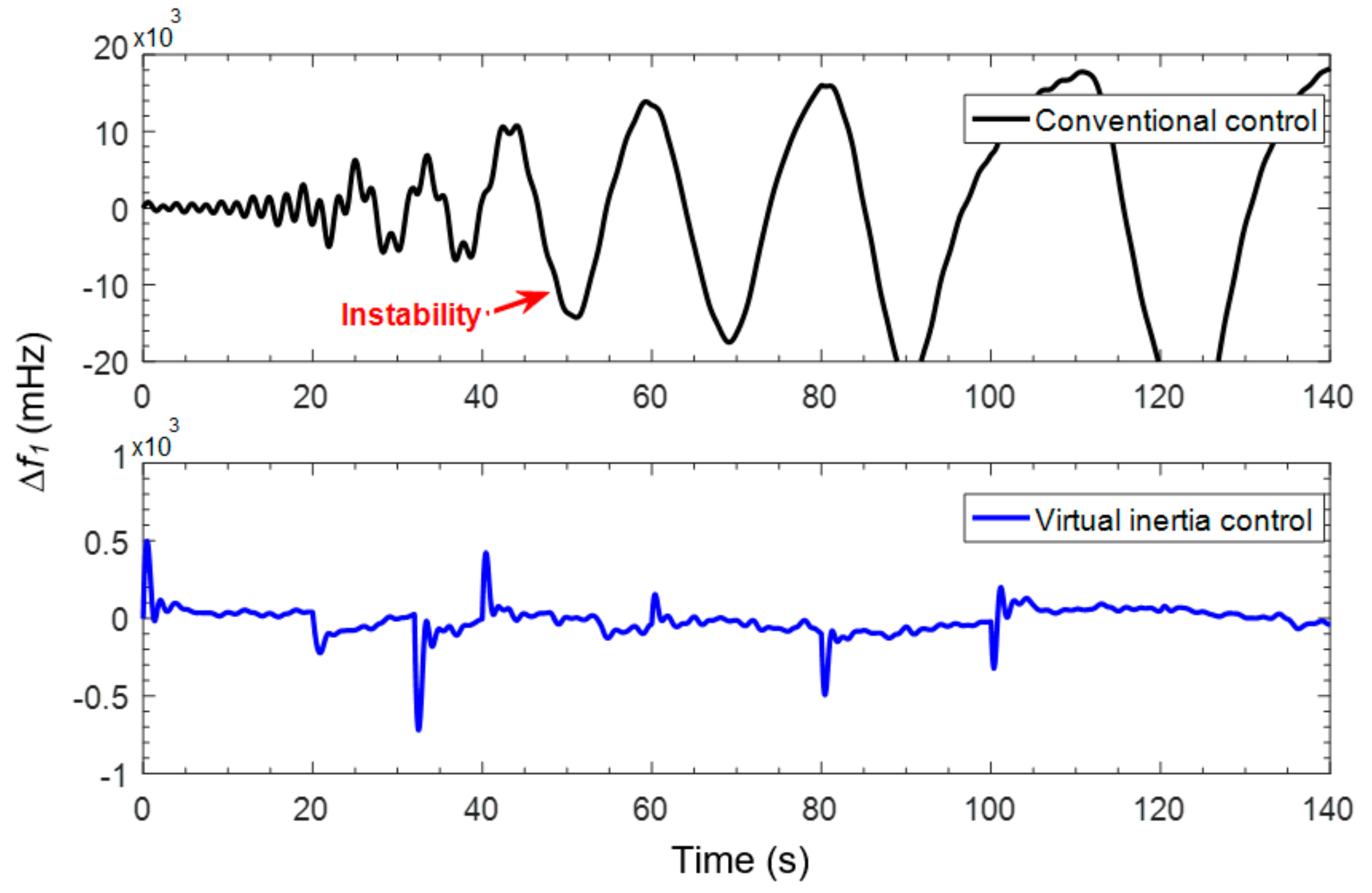
4.3. Multiple Disturbances in Renewable Energy and Load Demand
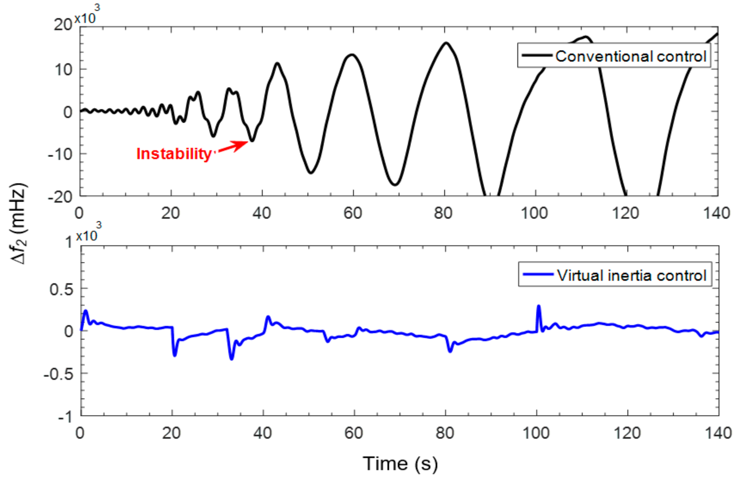
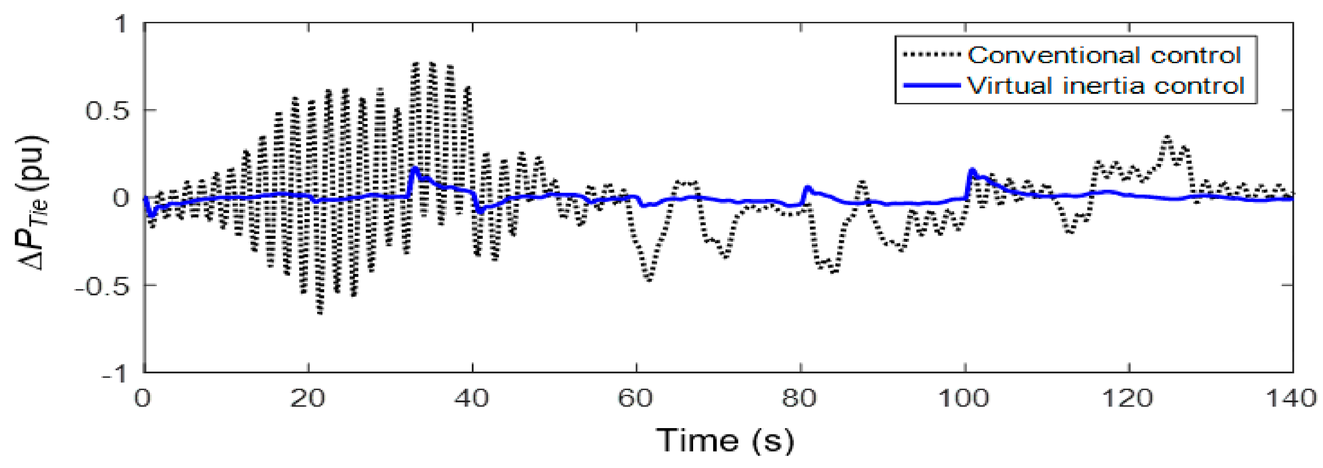
To perform a more drastic simulation, the interconnected power system is investigated under the conditions of multiple disturbances (See Figure 8) and low system inertia (i.e., 50% reduction of its nominal values in each area). During multiple operations in loads and RESs, the system response of the interconnected power system is oscillating with larger deviations, due to the system inertia reduction (See Figure 9, Figure 10 and Figure 11). Clearly, the system inertia reduction is affecting performance, stability and the resiliency of interconnected power systems. The proposed virtual inertia control can maintain the frequency deviation within the accepted frequency operating standard of ±500 mHz in both areas (Provided by National Electric Market (NEM), which is in line with mainland frequency operating standards for interconnected system [28]). In the case of conventional control (i.e., only primary and secondary/LFC controls), the frequency response of the interconnected power system gradually turns into instability, causing cascading outages.
4.4. High Penetration Level of Renewable Energy and Load Demand
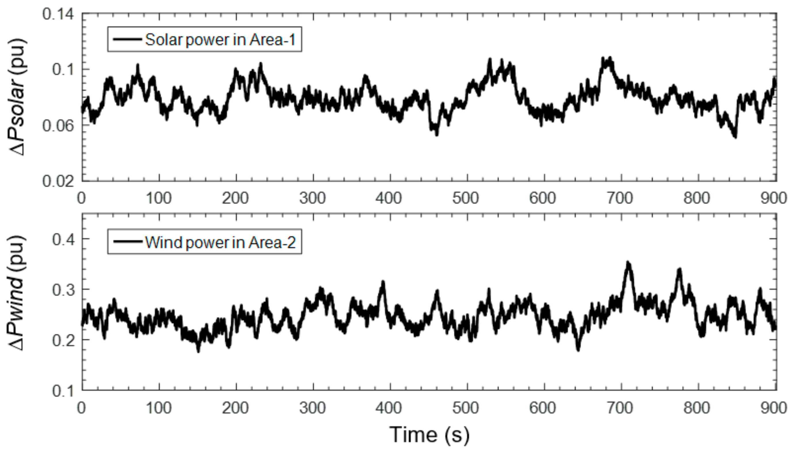
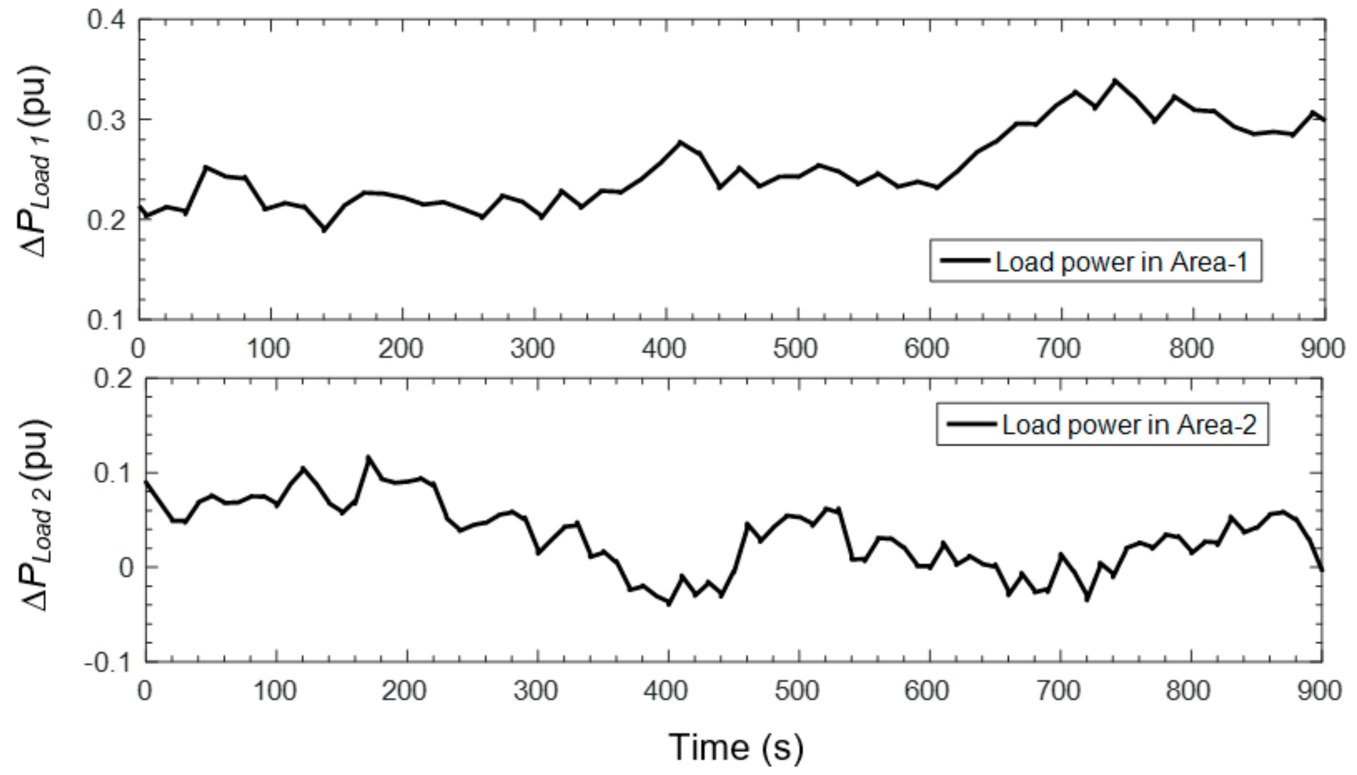
Multiplicity in numerous nature of load/generation, RESs, and severe variations of system operation, are identified as significant characteristics of interconnected power systems. Based on this test scenario, the interconnected power system is examined under different conditions of high penetration level of wind/solar farms in both areas; high fluctuated load demand in both areas as shown in Figure 12 and Figure 13 and Table 2. These extreme operations demonstrate the important dynamic effect of the real operations of interconnected power systems, and also verify the robustness of the proposed control strategy over high-level RESs/loads penetration and system inertia changes. Therefore, the effect of high penetration of RESs on the overall frequency and tie-line power behavior of the interconnected power system is clearly demonstrated by such a severe test contingency.
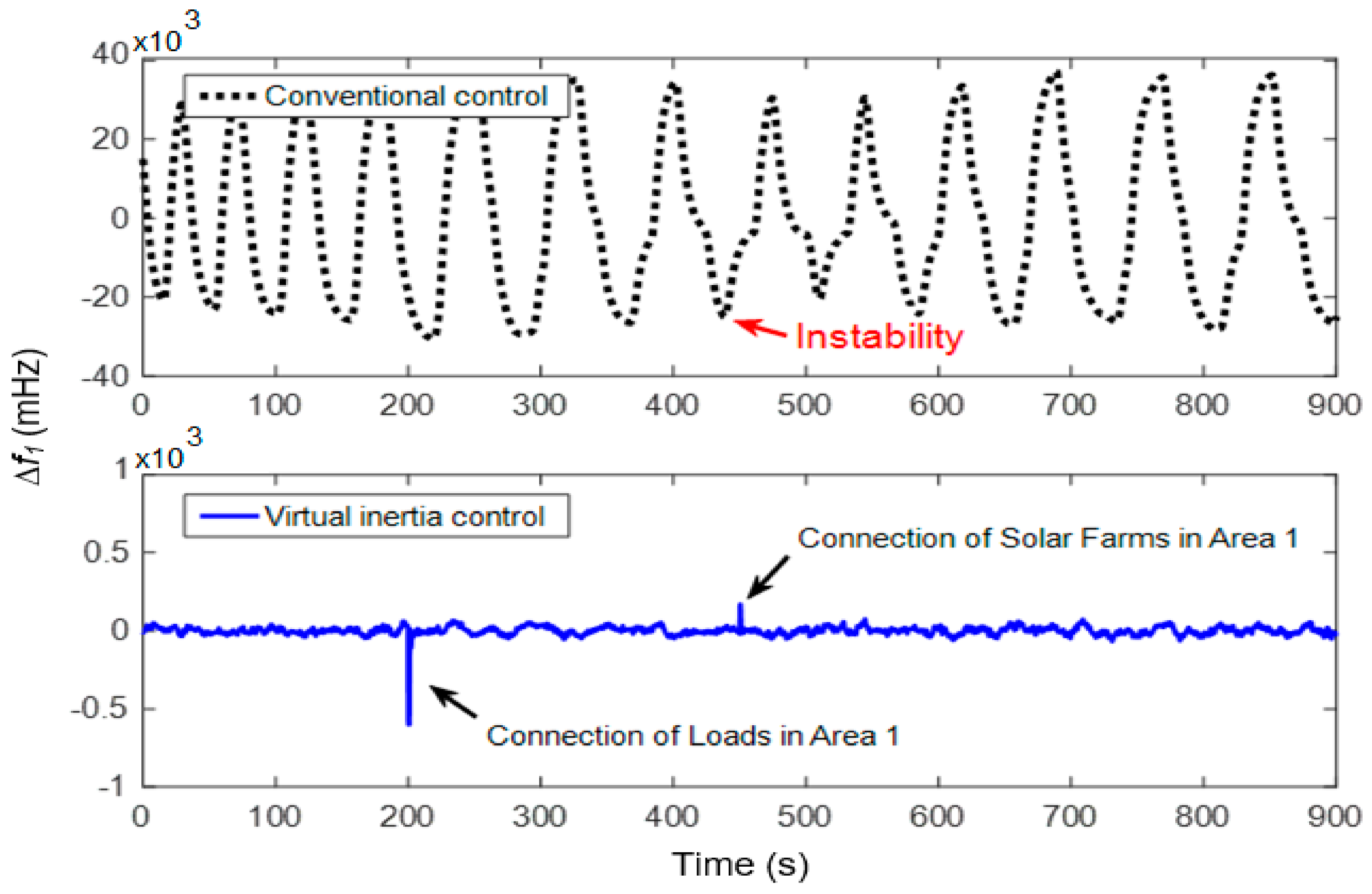
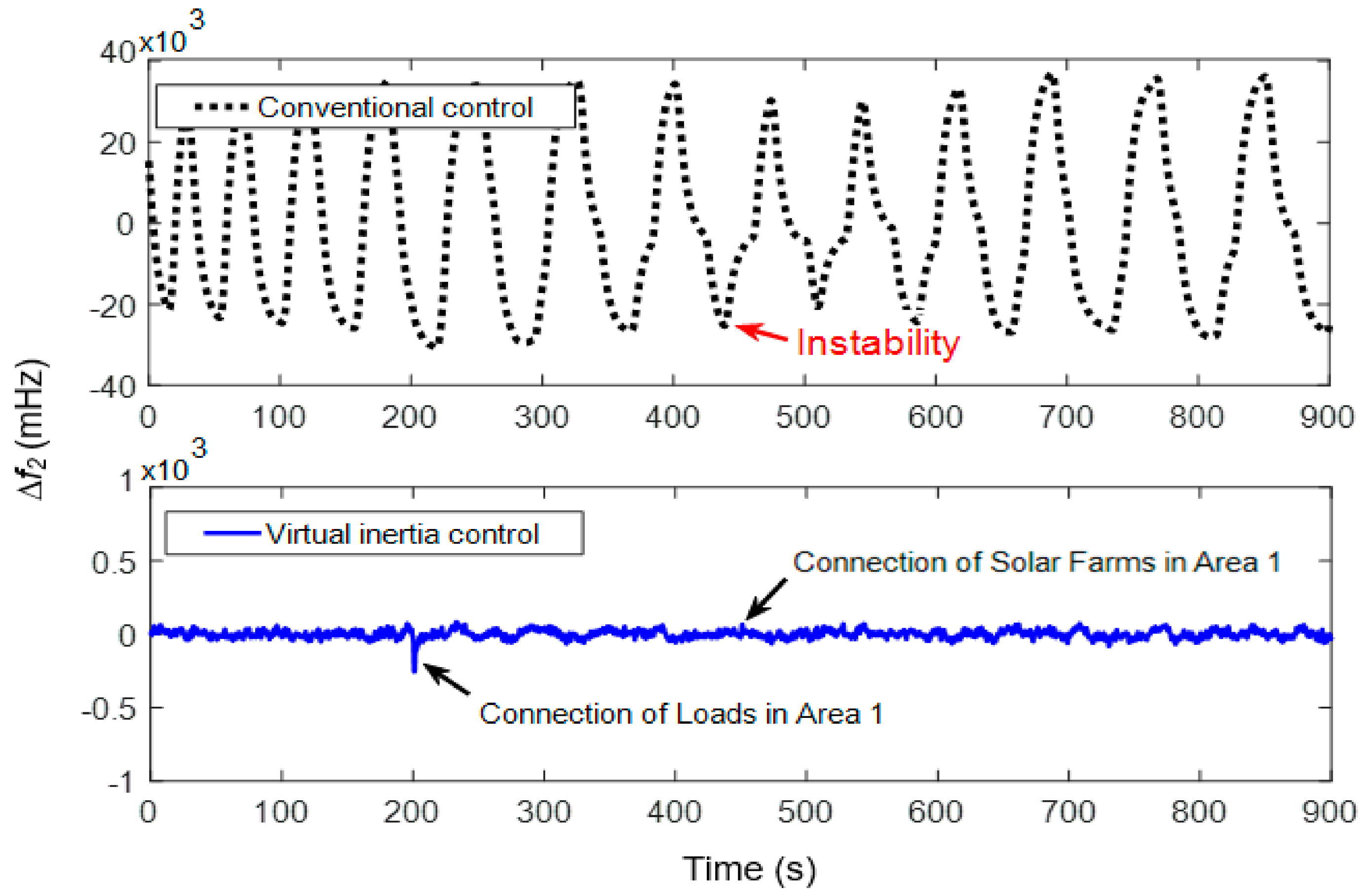
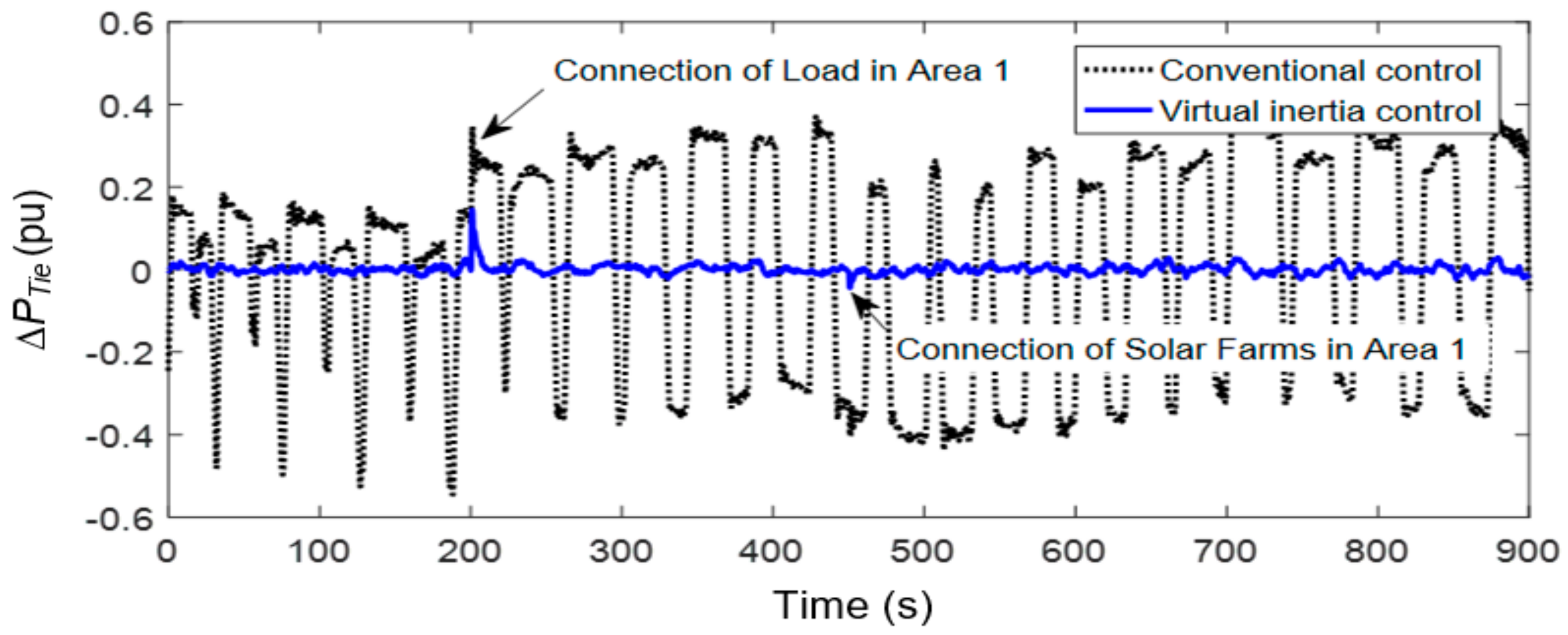
To carry out an extreme test scenario, the interconnected power system has been examined under the situation of extremely low system inertia (reduced 70% from its initial values). During high penetration of loads and RESs, it is found that the system response of the interconnected power system fluctuates severely, with larger deviations due to critical inertia reduction (See Figure 14, Figure 15 and Figure 16). Obviously, the critical inertia reduction caused by high RESs penetration mainly affects performance, stability and the resiliency of interconnected power systems. During connections of solar farms and loads in Area-1, the virtual inertia control can effectively maintain frequency deviations within the accepted frequency operating standard of ±500 mHz in both areas (Provided by NEM mainland frequency operating standards for interconnected system [28]). In the case of conventional control (i.e., only primary and secondary/LFC controls), the frequency response of the interconnected system could not maintain stability, causing a severe system collapse and total power blackout.
Therefore, the simulation results ensure that the virtual inertia control is able to decrease the transient frequency and tie-line power changes and improve the robustness of the system response under severe load changes, high-level RESs penetration, and variations of system inertia.
Table 3 reveals the absolute maximum frequency deviation of the system under high RESs penetration and severe load changes, when the inertia of the system is fixed as low, medium and high. The table shows that when the inertia of the system reduces, maximum deviations of system frequency arise. It is observed that conventional control could not maintain the frequency deviation during the conditions of medium and low system inertia, leading to higher frequency deviation. This situation (i.e., high frequency deviation caused by high-level RESs penetration) may cause the loss of a major generation, or severe system collapses, leading to the blackouts. In contrast, the absolute maximum frequency deviation of the virtual inertia control is fewer than all cases with systems using conventional control. These results indicate that the proposed control technique is robust to high-level RESs/load penetration and extreme inertia changes.
5. Conclusions
In this work, a novel application to virtual inertia control-based derivative control techniques is proposed to improve frequency performance and stability of interconnected systems with high RESs penetration. The derivative control method has been applied to control the active power of the ESS in the interconnected system, emulating inertia power. The proposed control technique could simply be applied to any class of multi-area systems with different characteristics, complexity and size. A comprehensive sensitivity analysis of inertia control parameters is also performed to demonstrate the actual effects of inertia imitation based on system stability and performance. The simulation results show that virtual inertia control is effective to suppress frequency deviation of the interconnected power system during severe contingencies. Nevertheless, the virtual inertia control system provides the desired stability and performance against high RES penetration, serious load disturbances, and a low moment of inertia, thus avoiding instability and system collapses. Compared with the conventional control, the proposed virtual inertia control not only reduces the peak frequency and tie-line power deviations, but also improves the robustness performance of the system. The significant conclusion concerning the studied system may be generalized to other multi-area power systems that experience similar challenges in high-level RESs penetration. Therefore, the proposed control technique will be significant and beneficial for further study of active power and frequency control with virtual inertia control competencies, considering HVAC links and high penetration level of RESs. Ultimately, the proposed virtual inertia control can effectively contribute to a better exploitation of RESs of interconnected power systems, while maintaining robustness of system operation.
Acknowledgments
This research was supported by the Power System and Renewable Energy Laboratory (MITANI Lab), Kyushu Institute of Technology, Japan. The authors are grateful for the feedbacks of anonymous reviewers and the editors of this journal; their innovative idea and suggestion help us a lot in improving the quality of this article.
Author Contributions
This research was a collaborative effort between the authors. Thongchart Kerdphol proposed the analysis of virtual inertia control for interconnected power systems and wrote the paper. Fathin Saifur Rahman provided theoretical knowledge for inertia analysis. Yasunori Mitani provided theoretical knowledge in the energy and control domain and reviewed the paper.
Conflicts of Interest
The authors declare no conflict of interest.
References
- Deepak, M.; Abraham, R.J.; Gonzalez-Longatt, F.M.; Greenwood, D.M.; Rajamani, H.S. A novel approach to frequency support in a wind integrated power system. Renew. Energy 2017, 108, 194–206. [Google Scholar] [CrossRef]
- El-Hendawi, M.; Gabbar, H.; El-Saady, G.; Ibrahim, E.-N. Control and EMS of a Grid-Connected Microgrid with Economical Analysis. Energies 2018, 11, 129. [Google Scholar] [CrossRef]
- Bevrani, H.; Watanabe, M.; Mitani, Y. Power System Monitoring and Control; John Wiley & Sons: Hoboken, NJ, USA, 2014. [Google Scholar]
- Küfeoğlu, S.; Lehtonen, M. Macroeconomic assessment of voltage sags. Sustainability 2016, 8, 1304. [Google Scholar] [CrossRef]
- Zhao, J.; Lyu, X.; Fu, Y.; Hu, X.; Li, F. Coordinated Microgrid Frequency Regulation Based on DFIG Variable Coefficient Using Virtual Inertia and Primary Frequency Control. IEEE Trans. Energy Convers. 2016, 31, 833–845. [Google Scholar] [CrossRef]
- D’Arco, S.; Suul, J.A.; Fosso, O.B. Small-signal modeling and parametric sensitivity of a virtual synchronous machine in islanded operation. Int. J. Electr. Power Energy Syst. 2015, 72, 3–15. [Google Scholar] [CrossRef] [Green Version]
- Tamrakar, U.; Shrestha, D.; Maharjan, M.; Bhattarai, B.; Hansen, T.; Tonkoski, R. Virtual Inertia: Current Trends and Future Directions. Appl. Sci. 2017, 7, 654. [Google Scholar] [CrossRef]
- Liu, J.; Miura, Y.; Ise, T. Comparison of Dynamic Characteristics between Virtual Synchronous Generator and Droop Control in Inverter-Based Distributed Generators. IEEE Trans. Power Electron. 2016, 31, 3600–3611. [Google Scholar] [CrossRef]
- Van De Vyver, J.; De Kooning, J.D.M.; Meersman, B.; Vandevelde, L.; Vandoorn, T.L. Droop Control as an Alternative Inertial Response Strategy for the Synthetic Inertia on Wind Turbines. IEEE Trans. Power Syst. 2016, 31, 1129–1138. [Google Scholar] [CrossRef]
- Thiesen, H.; Jauch, C.; Gloe, A. Design of a system substituting today’s inherent inertia in the European continental synchronous area. Energies 2016, 9. [Google Scholar] [CrossRef]
- Chen, D.; Xu, Y.; Huang, A.Q. Integration of DC Microgrids as Virtual Synchronous Machines into the AC Grid. IEEE Trans. Ind. Electron. 2017, 64, 7455–7466. [Google Scholar] [CrossRef]
- Kerdphol, T.; Rahman, F.S.; Mitani, Y.; Hongesombut, K.; Küfeoğlu, S. Virtual inertia control-based model predictive control for microgrid frequency stabilization considering high renewable energy integration. Sustainability 2017, 9, 773. [Google Scholar] [CrossRef]
- Kerdphol, T.; Rahman, F.S.; Mitani, Y.; Watanabe, M.; Kufeoglu, S. Robust Virtual Inertia Control of an Islanded Microgrid Considering High Penetration of Renewable Energy. IEEE Access 2018, 6, 625–636. [Google Scholar] [CrossRef]
- Bevrani, H.; Francois, B.; Ise, T. Microgrid Dynamics and Control; John Wiley & Sons: Hoboken, NJ, USA, 2017; ISBN 0780345304. [Google Scholar]
- Nomura, S.; Tsutsui, H.; Tsuji-Iio, S.; Shimada, R. Flexible power interconnection with SMES. IEEE Trans. Appl. Supercond. 2006, 16, 616–619. [Google Scholar] [CrossRef]
- Dechanupaprittha, S.; Hongesombut, K.; Watanabe, M.; Mitani, Y.; Ngamroo, I. Stabilization of tie-line power flow by robust SMES controller for interconnected power system with wind farms. IEEE Trans. Appl. Supercond. 2007, 17, 2365–2368. [Google Scholar] [CrossRef]
- Ngamroo, I. Robust SMES controller design based on inverse additive perturbation for stabilization of interconnected power systems with wind farms. Energy Convers. Manag. 2010, 51, 459–464. [Google Scholar] [CrossRef]
- Abu-Siada, A.; Islam, S. Application of SMES unit in improving the performance of an AC/DC power system. IEEE Trans. Sustain. Energy 2011, 2, 109–121. [Google Scholar] [CrossRef]
- Bevrani, H. Robust Power System Frequency Control; Springer: New York, NY, USA, 2014. [Google Scholar]
- Bevrani, H.; Mitani, Y.; Tsuji, K. Robust decentralized AGC in a restructured power system. Energy Convers. Manag. 2004, 45, 2297–2312. [Google Scholar] [CrossRef]
- Rerkpreedapong, I.; Hasanovic, A.; Feliachi, A. Robust Load Frequency Control Using Genetic Algorithms and Linear Matrix Inequalities. IEEE Trans. Power Syst. 2003, 18, 855–861. [Google Scholar] [CrossRef]
- Mohamed, T.H.; Bevrani, H.; Hassan, A.A.; Hiyama, T. Decentralized model predictive based load frequency control in an interconnected power system. Energy Convers. Manag. 2011, 52, 1208–1214. [Google Scholar] [CrossRef]
- Kundur, P. Power System Stability and Control; McGraw-Hill: New York, NY, USA, 1994. [Google Scholar]
- Lee, D.J.; Wang, L. Small-signal stability analysis of an autonomous hybrid renewable energy power generation/energy storage system part I: Time-domain simulations. IEEE Trans. Energy Convers. 2008, 23, 311–320. [Google Scholar] [CrossRef]
- Bevrani, H.; Habibi, F.; Babahajyani, P.; Watanabe, M.; Mitani, Y. Intelligent frequency control in an AC microgrid: Online PSO-based fuzzy tuning approach. IEEE Trans. Smart Grid 2012, 3, 1935–1944. [Google Scholar] [CrossRef]
- Lopes, L.A. Self-Tuning Virtual Synchronous Machine: A Control Strategy for Energy Storage Systems to Support Dynamic Frequency Control. IEEE Trans. Energy Convers. 2014, 29, 833–840. [Google Scholar] [CrossRef]
- Datta, M.; Ishikawa, H.; Naitoh, H.; Senjyu, T. Frequency control improvement in a PV-diesel hybrid power system with a virtual inertia controller. In Proceedings of the 2012 7th IEEE Conference on Industrial Electronics and Applications (ICIEA 2012), Singapore, 18–20 July 2012; pp. 1167–1172. [Google Scholar] [CrossRef]
- Australian Energy Market Commission (AEMC) Reliability Panel. Application of Frequency Operating Standards during Peroids of Supply Scarcity; Final Determination; AEMC: Sydney, Australia, 2009. [Google Scholar]
Figure 1.
Simplified model of the modern interconnected power system with virtual inertia control.

Figure 2.
Dynamic model of the modern interconnected power system with virtual inertia control.

Figure 3.
Dynamic model of the designed controller for virtual inertia emulation.

Figure 4.
Eigenvalue trajectory of dominant poles over variations of virtual inertia control gain in Area-1 (With KVI2 = 0.03).
Figure 4.
Eigenvalue trajectory of dominant poles over variations of virtual inertia control gain in Area-1 (With KVI2 = 0.03).

Figure 5.
Eigenvalue trajectory of dominant poles over variations of virtual inertia control gain in Area-2 (With KVI1 = 1.54).
Figure 5.
Eigenvalue trajectory of dominant poles over variations of virtual inertia control gain in Area-2 (With KVI1 = 1.54).

Figure 6.
System response in the circumstance of normal system inertia.

Figure 7.
System response in the circumstance of system inertia reduction of 50%.

Figure 8.
Multiple operating disturbances in solar irradiation, wind speed and load demand.

Figure 9.
Frequency response in Area-1 in the circumstance of low inertia.

Figure 10.
Frequency response in Area-2 in the circumstance of low inertia.

Figure 11.
Tie-line power change in the circumstance of low inertia.

Figure 12.
Solar and wind power profiles in each area.

Figure 13.
Load power patterns in each area.

Figure 14.
Frequency response in Area-1 in the circumstance of extremely low inertia.

Figure 15.
Frequency response in Area-2 in the circumstance of extremely low inertia.

Figure 16.
Tie-line power change in the circumstance of extremely low inertia.


Table 1.
Simulation parameters for the interconnected power system.
| Parameters | Area-1 | Area-2 |
|---|---|---|
| Frequency bias factor, Bi (p.u.MW/Hz) | 0.3483 | 0.3827 |
| Area control error gain, Ki (s) | 0.3 | 0.2 |
| Governor time constant, Tg (s) | 0.08 | 0.06 |
| Turbine time constant, Tt (s) | 0.4 | 0.44 |
| Droop constant, R (Hz/p.u.MW) | 3 | 2.73 |
| System inertia constant, H (p.u.MW s) | 0.083 | 0.1010 |
| Damping coefficient, D (p.u.MW/Hz) | 0.015 | 0.016 |
| Virtual inertia control gain, KVI (s) | 1.54 | 1.75 |
| Virtual inertia time constant, TVI (s) | 10 | 10 |
| Solar system time constant, TPV (s) | 1.3 | - |
| Wind turbine time constant, TWT (s) | - | 1.5 |
| Maximum limit of valve gate, VU (p.u.MW) | 0.5 | 0.5 |
| Minimum limit of valve gate, VL (p.u.MW) | −0.5 | −0.5 |
| System base (MW) | 15 | |
| Synchronizing coefficient, T12 (p.u.MW/Hz) | 0.08 | |
| Area capacity ratio between two areas, α12 | −0.6 | |
Table 2.
Different disturbance operations in the interconnected power system.
| Source of Disturbance | Operating Time (s) | Capacity (MW) |
|---|---|---|
| Solar farm in Area-1 | 450 s | 2.70 |
| Wind farm in Area-2 | initial | 5.56 |
| Load in Area-1 | 200 s | 5.20 |
| Load in Area-2 | initial | 2.05 |
Table 3.
Assessment index of frequency deviation of the interconnected system.
| Case Study | Mean Absolute Frequency Deviation (Hz) | |||
|---|---|---|---|---|
| Conventional Control | Virtual Inertia Control | |||
| ∆f1 | ∆f2 | ∆f1 | ∆f2 | |
| High system inertia (95%) | 0.0280 | 0.0277 | 0.0221 | 0.0228 |
| Medium system inertia (50%) | 16.6450 | 16.6422 | 0.0224 | 0.0245 |
| Low system inertia (30%) | 19.9598 | 19.9842 | 0.0227 | 0.0261 |
© 2018 by the authors. Licensee MDPI, Basel, Switzerland. This article is an open access article distributed under the terms and conditions of the Creative Commons Attribution (CC BY) license (http://creativecommons.org/licenses/by/4.0/).
Share and Cite
MDPI and ACS Style
Kerdphol, T.; Rahman, F.S.; Mitani, Y. Virtual Inertia Control Application to Enhance Frequency Stability of Interconnected Power Systems with High Renewable Energy Penetration. Energies 2018, 11, 981. https://doi.org/10.3390/en11040981
AMA Style
Kerdphol T, Rahman FS, Mitani Y. Virtual Inertia Control Application to Enhance Frequency Stability of Interconnected Power Systems with High Renewable Energy Penetration. Energies. 2018; 11(4):981. https://doi.org/10.3390/en11040981
Chicago/Turabian StyleKerdphol, Thongchart, Fathin Saifur Rahman, and Yasunori Mitani. 2018. "Virtual Inertia Control Application to Enhance Frequency Stability of Interconnected Power Systems with High Renewable Energy Penetration" Energies 11, no. 4: 981. https://doi.org/10.3390/en11040981
Note that from the first issue of 2016, this journal uses article numbers instead of page numbers. See further details here.