A Robust Suboptimal Current Control of an Interlink Converter for a Hybrid AC/DC Microgrid


Department of Electrical and Information Engineering, Seoul National University of Science and Technology, Seoul 01811, Korea
*
Authors to whom correspondence should be addressed.
Energies 2018, 11(6), 1382; https://doi.org/10.3390/en11061382
Submission received: 23 April 2018
/
Revised: 24 May 2018
/
Accepted: 25 May 2018
/
Published: 29 May 2018
(This article belongs to the Special Issue 18th International Symposium on Advanced Intelligent Systems (ISIS2017))
Abstract
:A hybrid AC/DC microgrid is established with the aim of exploiting numerous types of renewable energy to meet the needs of different loads. The microgrid is decomposed by AC DC sub-grids which are connected by an interlink converter (IC). To maintain the security and reliability of the microgrid, an automatic controller for the interlink converter is needed. In this paper, we propose a Linear Matrix Inequalities (LMI)-based current control method for the interlink converter. As the main features here, the interlink converter permits bidirectional power exchange between both sub-grids when a power–demand imbalance occurs in one sub-grid regardless of the converter system parameters. Simulations with various filter parameters are performed using the Matlab/Simulink software to validate the effectiveness of the proposed controller. In comparison with the existing Linear Quadratic Regulator (LQR)-based current control, the proposed method is more robust against unknown system parameters and high load perturbation.
1. Introduction
As the technology changes and the consumption increases, the need for new efficient energy generation rises. Microgrid holds a potential concept for more reliable and clean energy supply. A microgrid is a set of interconnected small-scale power sources so-called distributed generators (DG), loads and energy storage devices that work together as a controlled load or generator. The DG can be wind farms, hydroelectric power, power-voltaic or fuel cell system [1,2]. A flywheel, capacitor, or battery is the type of energy storage systems. A utility grid connects to the microgrid in parallel under normal situation. Then, when a fault occurs in the utility grid, microgrid disconnects from the utility grid and changes its operating mode in stand-alone mode.
Conventionally, a microgrid is a group of traditional AC energy sources supplying AC loads. Integrating it into the main grid is relatively easy and requires less complicated structure. However, some renewable energies such as fuel cells and solar systems are DC inherently, and some consumer loads such as light and home appliances use DC power. To integrate DC loads and DC sources in the microgrid, a double inversion is needed: from DC to AC at the system and AC to DC at the load, which can cause power losses. Thus, implementing DC microgrid could be a solution to lessen the energy losses. Furthermore, a hybrid AC/DC microgrid is developed to fully exploit the AC and DC power sources [2]. A hybrid AC/DC microgrid consists of two sub-grids based on their current flow type: AC and DC sub-grids. Local AC loads and AC sources are integrated into one AC sub-grid, while DC sub-grid is composed of the DC loads and DC sources.
Generally, microgrid runs in two operating modes: grid connected and stand-alone. Microgrid must be able to maintain the voltage and frequency stability in both modes and the switching time [3,4]. When microgrid is in grid-connected mode, frequency stability is guaranteed by the utility grid as it performs as the primary source in the AC sub-grid. Hence, the remaining problem is the voltage stability in both sub-grids. However, when the utility grid disconnects from the microgrid, the problem gets more challenging as an abrupt change in the load will disrupt power supply–demand balance, which significantly influences the voltage and frequency stability. In addition, high penetration of renewable generation systems with unpredictable output power fluctuations may produce higher frequency/voltage deviation in stand-alone microgrid operation.
A large number of DGs is incorporated at the distribution level with power electronic converter interfaces. In a hybrid AC/DC microgrid, an additional converter exists in the interconnection of AC and DC sub-grids, which is commonly referred to as the interlink converter (IC). The IC allows a bidirectional energy exchange between them. When the local sources could not fulfill the demand, or there exists a surplus power in a sub-grid, necessary power is exchanged to manage the power supply–demand balance. In this regard, the IC control could be a key to maintain the power supply–demand balance in a hybrid AC/DC microgrid [5,6].
Generally, bidirectional AC-DC converter controller consists of an outer- and an inner-loop control. The outer control produces the reference value used for the inner-loop control. It is mainly a droop control method based on frequency and voltage deviation. Meanwhile, the inner-loop control can be a voltage/current controller and is traditionally performed by a proportional-integral (PI) control. Commonly, PI control does not consider the proper model of the system to describe the system behavior. It is well-known that a PI control can lead to a startup overshoot due to the integral term. Hence, to take into account the system behavior, several studies investigate the design procedures to determine the gain for PI controller; for example, a Smith predictor PI is employed in a single-phase bidirectional AC-DC converter for battery charger [7]. Implementing this technique for an IC voltage/current controller requires a more complicated design procedure since the system is a multivariable system. Thus, numerous control strategies propose a model-based voltage/current controller for an IC. In [8], by employing an adaptive hysteresis control method, the switching loss of the traditional hysteresis control is reduced. Furthermore, a model predictive control (MPC) is proposed to optimize the control input [9]. However, those methods yield a variable switching frequency. Furthermore, to include the switching state in the optimization cost function, a finite state MPC is proposed in [10]. This method requires high sampling frequency.
In the interlink converter, a low-pass filter is implemented with the purpose of reducing the voltage and current distortion as a result of its high frequency switching. The simplest low-pass filter can be decomposed by a resistor–capacitor (RC) or resistor–inductor (RL) circuit. The filter parameters are essential for the design procedure. In such model-based control schemes [8,9,10], it is assumed that the parameters in the model are known. However, due to manufacturing and thermal effects, the inductors, resistors, and capacitors can be different from the designed values. Even though the simulation result shows that the scheme in [10] is robust against uncertain filter parameters, the uncertain filter parameters are not considered in the control design. Thus, the robustness is limited. Nonlinear controller based on backstepping method is studied in [11]. This method considers the load perturbation as a disturbance, but does not include the filter parameters uncertainty. In the literature, there are only a few results in which the filter parameters uncertainty is included in the current/voltage control design for IC. For example, in [12], a robust control method based on H infinity is employed to track the current reference while considering the perturbation on parameters uncertainty. However, it requires high analytical skill to design the performance weight function. Sliding mode control method is proposed by [13] to consider the uncertain system parameter. However, the discontinue control input can cause chattering and is sensitive to noise. In [14], integral fuzzy logic is applied in DC/DC converter. The method adopts a small-signal model which is unable to achieve global stabilization.
This paper proposes a Linear Matrix Inequalities (LMI)-based Linear Quadratic Regulator (LQR) method to consider the performance with uncertain filter parameters. LMI-based robust control has been investigated for problems such as a UPS [15], and a grid-connected converter [16]. However, to the best of our knowledge, there is no significant work done on robust control of interlink converter using an LMI-based approach. In our previous work [17], LQR for current control of the IC is devised. In comparison with the PI control, the LQR-based current control shows superior performance in high loading condition. LQR is computed by solving the Riccati equation under the assumption that the parameters in the model are known, which corresponds to minimizing the quadratic cost with infinite horizon [18]. However, if uncertain parameters are taken into account to reflect the real situation, it is not possible to minimize the cost with infinite horizon. Towards this end, this paper computes a feedback control by minimizing the upper bound of the cost with the infinite horizon at every sampling instant. The control design procedure is formulated using LMI which provides computational efficiency. The resulting controller is suboptimal in the sense that the controller minimizes the upper bound of the infinite horizon cost. Furthermore, it results in robust performance of the IC since model uncertainties are taken into account in the middle of the cost minimization. From simulation results, it turns out that the proposed control indeed improves the robustness of the controller in high load variation.
2. Conventional Control of Microgrid
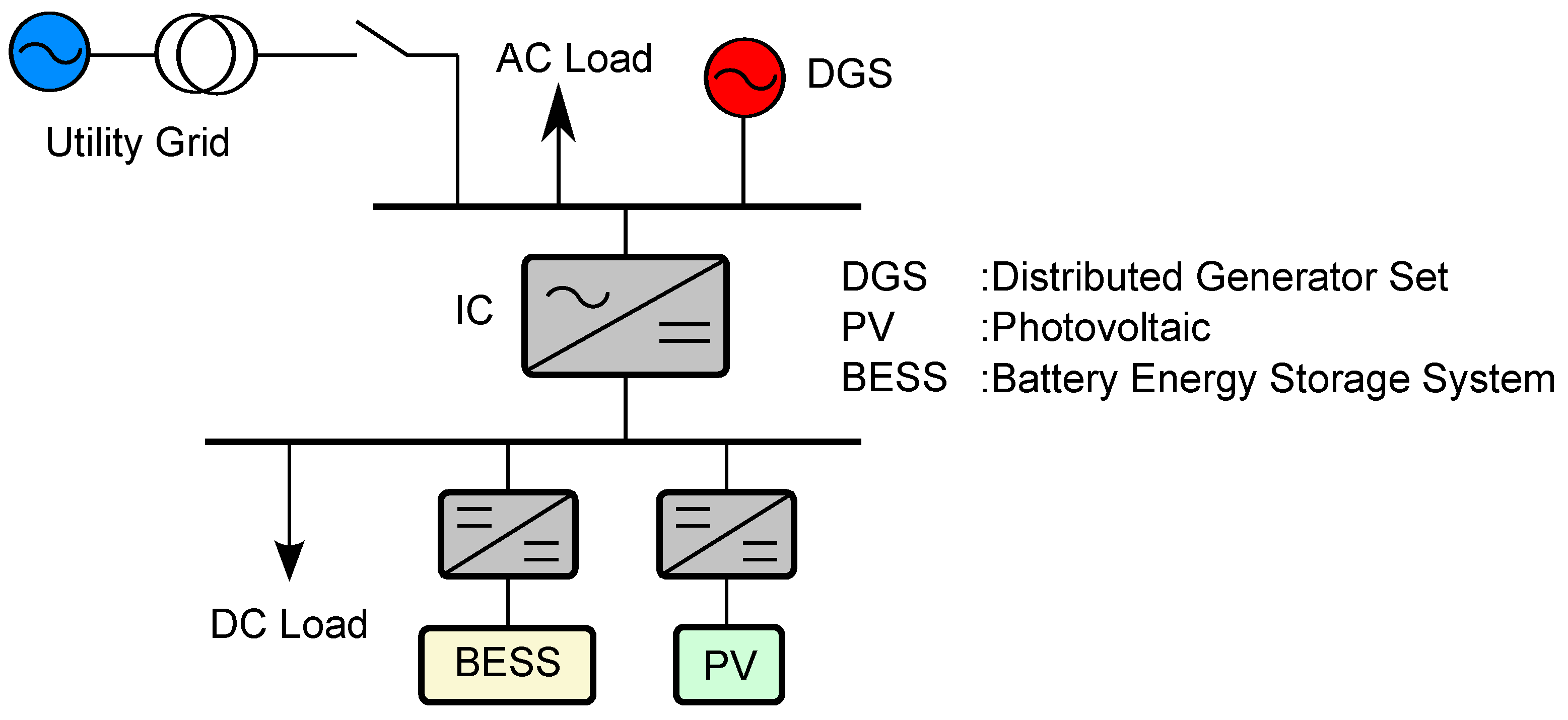
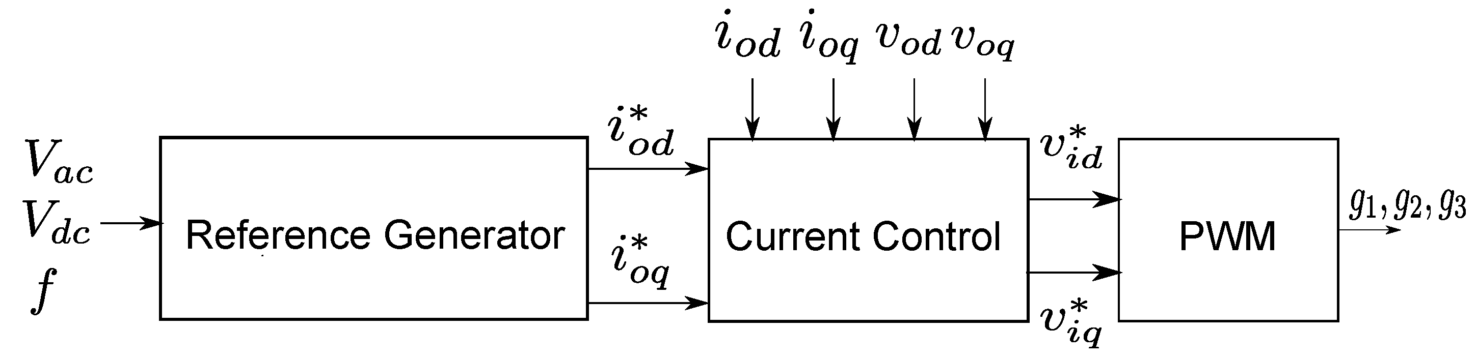
Figure 1 shows a hybrid AC/DC microgrid structure consisting of an AC and a DC sub-grid. Both have their local loads and sources and are coupled with an interlinking converter (IC). In grid-connected mode, the AC bus is connected to a utility grid through a transformer. A battery is connected to DC bus through a bidirectional DC/DC converter. In a hybrid microgrid, when a supply–demand imbalance occurs in one grid, and then necessary power need to be injected from the other grid. A control strategy for interlink converter (IC) aims to impose a proper power flowing through the IC. Figure 2 shows a typical control strategy for IC. The controller consists of a reference generator and current control. The reference generator is composed of a droop control and generates and for the current controller. Furthermore, a pulse-width modulator (PWM) produces the corresponding gating signals for the IC. In this section, the conventional IC control method is presented.
2.1. Reference Generator
As shown in Figure 2, the reference generator produces reference values for the IC current control. In this control loop, a droop control based on frequency and voltage deviations is implemented. Before explaining about the droop control for a hybrid microgrid, the droop control for individual AC and DC microgrid is discussed first.
2.1.1. AC Microgrid
The common technique to satisfy the power sharing between several distributed generators (DG) in AC microgrid is by employing AC droop control. The droop is given by
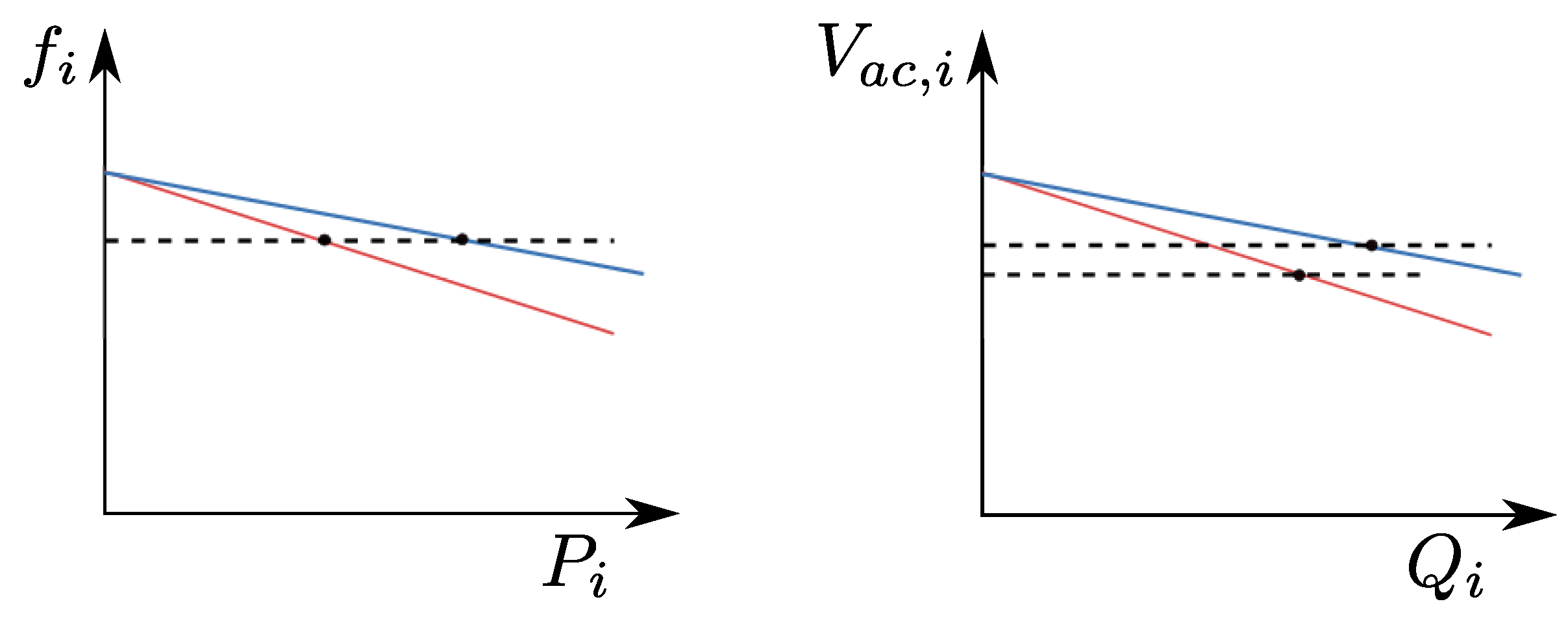
where are the frequency and voltage reference, respectively; are the frequency and voltage at no load, respectively; and are the generated active and reactive power of the ith distributed generator (DG), respectively. Figure 3 represents the P-f and Q-V droop control given by Equations (1) and (2). In the steady state, frequency and voltage of the distributed generators converge to the value presented by the dashed line shown in Figure 3 [5].
2.1.2. DC Microgrid
Similar to AC microgrid, a droop control is also used in DC microgrid, which is expressed by:
where are the output voltage reference and voltage at no load, respectively, and is droop characteristic of DC power source.
2.1.3. Hybrid Microgrid
Inspired by the droop control in each i-th DG, the IC controller augments the droop control owned by both grids. Note that the active power is related to the frequency deviation in AC microgrid, and it is corresponds to the voltage deviation in DC microgrid. Intuitively, comparing both values will indicate which microgrid has more severe active power imbalance. Per unit values is used to augment both values as they have different base unit. The following is the droop control for a hybrid microgrid
where and are the nominal value of frequency and DC voltage deviation in per unit, respectively, while and denote the droop coefficient for AC grid and DC grid, respectively. To consider the characteristic of frequency and DC voltage deviation, their nominal values are defined as:
Since reactive power does not exist in DC grid, the reactive power exchange is calculated based on the AC voltage deviation :
where
Furthermore, the current references are given by:
where and are the AC voltage in d (direct) and q (quadrature) frame, respectively.
2.2. Current Control
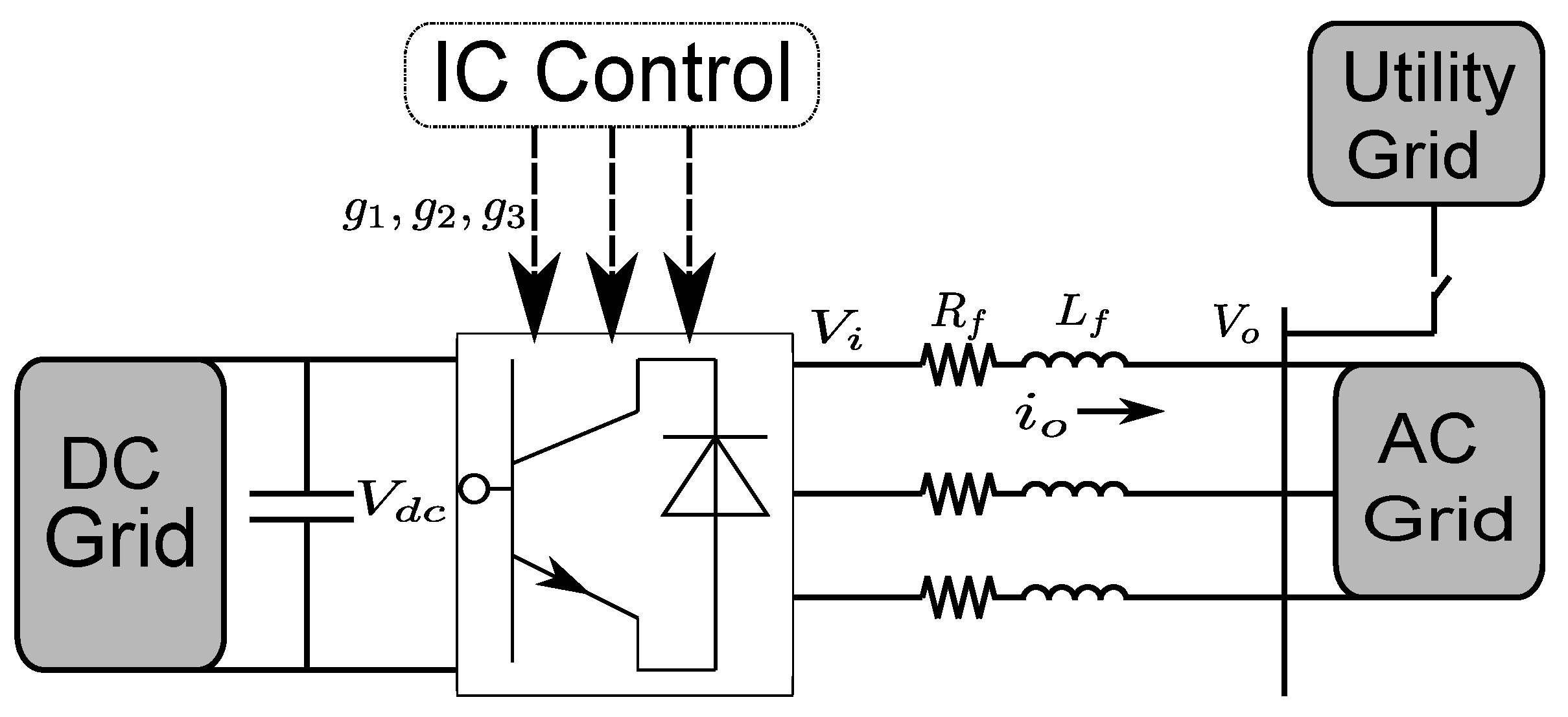
Figure 4 presents the circuit in the IC. An RL filter is connected to the IC to overcome the harmonics of current output. Applying a Kirchoff’s voltage law at the point of common coupling (PCC) , the three phase voltage at AC side can be written as
Applying -transformation yields:
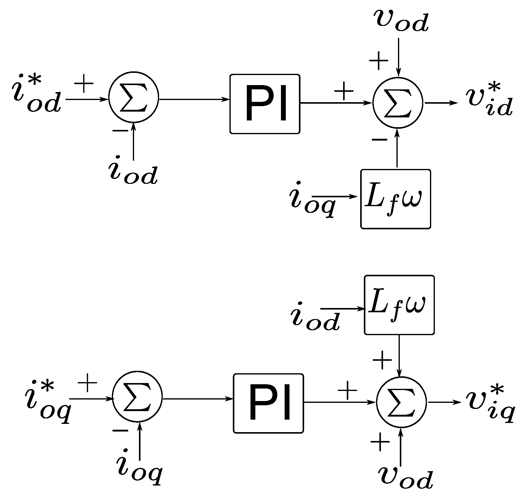
Conventionally, the controller generates the control input for and by separating Equation (7) into two SISO systems, then formulating two PI controllers, as shown in Figure 5. The controller assumes that the inverter bridge produces the required voltage, i.e., and , and that the rotating frequency is constant.
3. Problem Formulation
In this paper, rather than using a PI control for IC current control, model-based current control is proposed. Several studies have designed a model-based IC current control [12,17]. In those controllers, the filter connected through the IC, as shown in Figure 1, plays an important role in modeling the IC. However, due to manufacturing error on inductor and temperature effect on resistor , there might be uncertainty in the model parameters used for the controller design. In this paper, a model-based control for the IC is proposed such that it is robust against uncertain filter parameters.
First, let us consider the dynamic in Equation (7), which can be rewritten as a multivariable continuous-time state space model:
where is the state vector, is the control variable and is the disturbance. Both the state x and disturbance d are assumed to be measurable. With the uncertain model in mind, this paper aims to design a robust controller such that the state variable x converges to the state references generated by the aforementioned reference generator. In this paper, it is assumed that the filter parameters are uncertain but lie in known intervals. In other words, parameters and in matrices and are uncertain but satisfy:
Denote as the pair of the state-space matrices in Equation (8) correspond to the four possible combination of the extreme values of and :
By assuming that the system matrix pair belongs to a convex set made by those models in Equation (9), the uncertainty model allows the uncertain and . For further explanation of polytopic uncertain model, please refer to [19]. Hence, supposing that in Equation (8) is constant during the sampling period , the model Equation (8) can be discretized as
where , and
and k denotes the sampling time. Note that by, referring to Equation (9), the number of uncertain models are four .
The controller aims to eliminate the current error: despite model uncertainties. The model in Equation (10) is then augmented with an additional state variable which stands for integral of the current error. Defining new state variable , the resulting augmented model is written as:
where , and
where . Recall that the state x and disturbance d are measurable. Thus, to design the control such that the current converges to the reference, any state feedback control law can be employed as follows
In a certain model system, the gain K can be designed by any design method, e.g., pole-placement or classical LQR. To achieve robust performance despite the uncertain parameters, a robust control is designed such that it minimizes the upper bound of LQR cost with infinite horizon using LMI, which is presented in the next section.
4. Proposed Method
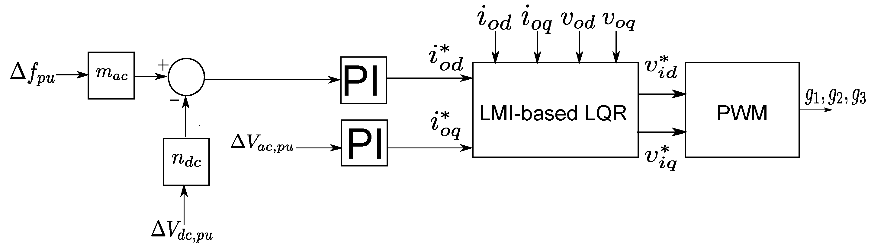
In this paper, the method depicted in Figure 6 is proposed. A modified method [5] is adopted to generate current references for the LMI-based LQR current control. In the outer-loop control, a PI controller is implemented for maintaining and . The droop gain and correspond to frequency deviation and DC voltage deviation, respectively, and are tuned to produce a proper power exchange driven by the IC current .
LMI-Based LQR Gain
In LQR problem, if the system model is exact, the LQR gain K in Equation (12) is calculated such that it minimizes the quadratic performance index:
Note that this problem aims to optimize the quadratic performance index over the whole time span. Thus, it is called the infinite horizon optimal control problem. For details, see [20]. However, uncertainties in the model make it difficult to solve the optimization problem. To tackle this problem, the feedback gain K is computed such that it minimizes the upper bound of at every sampling time. To this end, a convex optimization problem is formulated using LMI described in the following theorem [19].
Theorem 1.
For the ease of reading, the proof is presented in Appendix A, and a similar proof can be found in [19]. Note that the proposed method requires the selection of LQR parameters Q and R. By adopting the Bryson’s rule [21], the diagonal element of matrix can be defined by:
Meanwhile, the matrix R can be formulated as where is chosen by considering it as the weight of control input u in the cost function in Equation (13).
5. Simulation Result
In this section, the proposed method is verified in a hybrid microgrid using computer simulation. The system parameters are depicted in Table 1. The proposed IC control is tested to investigate its performance against power supply–demand imbalance in each of two sub-grids and uncertain parameters. In this paper, an LMI-based LQR method is implemented to make the current flowing through the IC equivalent with the desired value. To investigate the robustness of the proposed method, a random filter parameters , is tested. The LQR parameters are selected as and I.
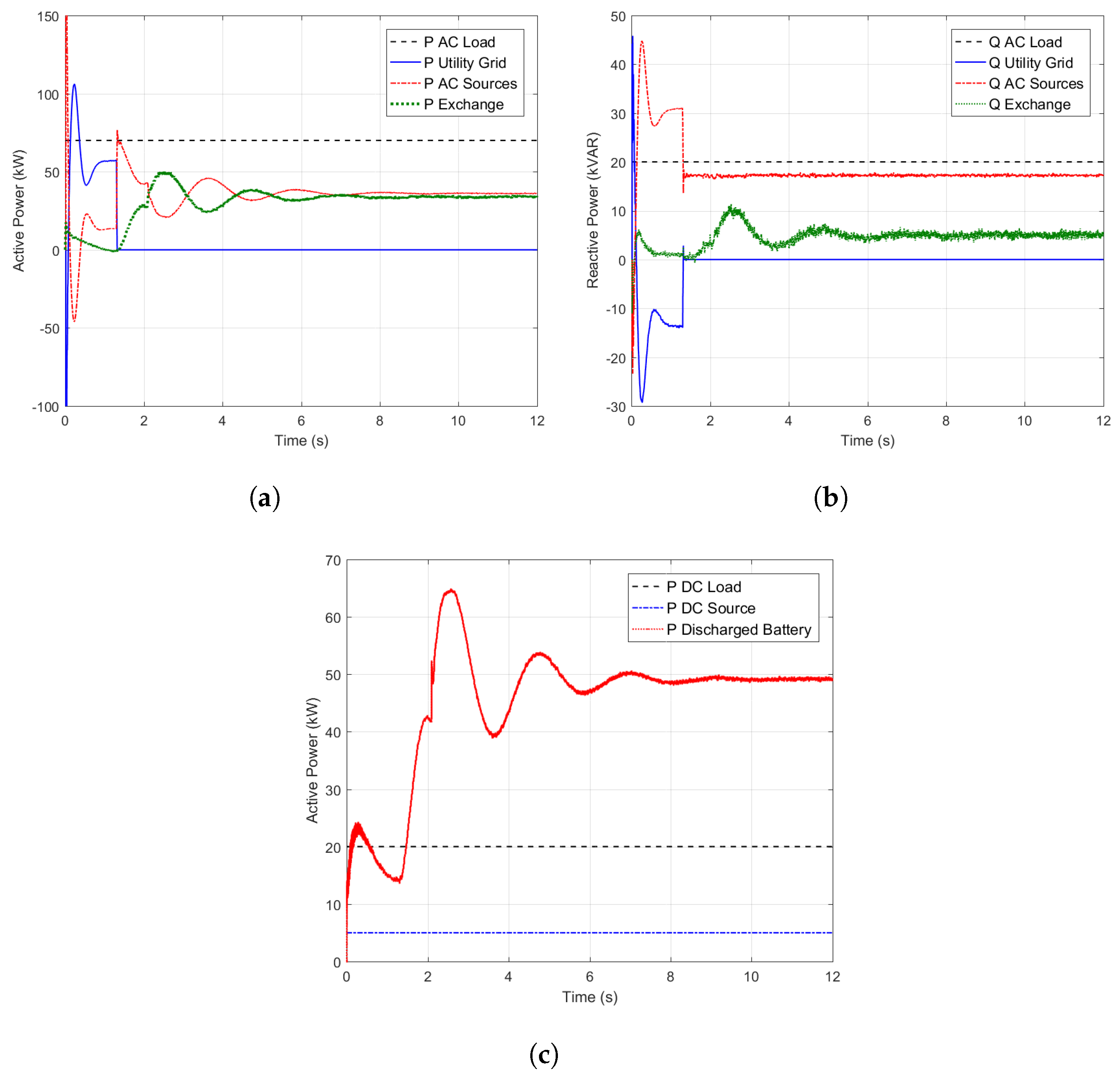
In the first case, it is assumed that power supply–demand imbalance occurs in AC sub-grid. The AC power rating is 60 kW, and the DC sub-grid has a battery with state-of-charge (SOC). A utility grid is connected to the system for first 1.3 s before the operating mode is shifted to a stand-alone operation mode. The IC rating is assumed to be 50 kW. Figure 7a,b shows the active and reactive power flow in both sub-grids. The AC and DC loads are a constant 70 kW/20 KVAR and 20 kW, respectively. In grid-connected mode, the utility grid can satisfy the power demand in AC grid. As shown in Figure 7c, the battery and the power source in DC grid can fulfill the demand in DC grid. Thus, there is no exchanged power between the grids. However, when the utility grid is disconnected to the system, the AC power source could not fulfill the AC load. Hence, 35 kW and 5 kVAR power are transferred from the DC. The positive sign in the power IC represents the power exchange direction from DC to AC side.
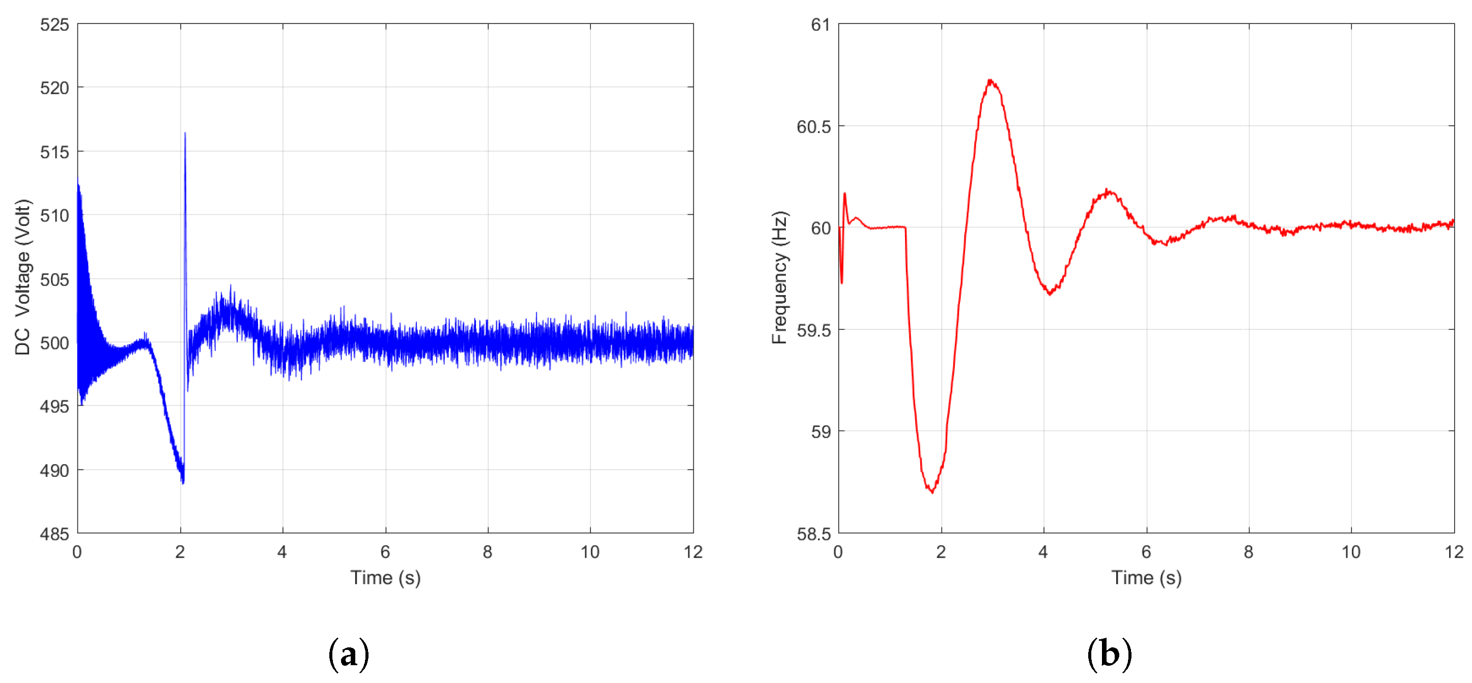
Figure 8a,b shows the DC voltage and frequency response due to the changing mode. In stand-alone mode, the imbalance occurs in AC grid, leading to decreased AC frequency. Then, the IC control prompts the DC grid to supply active power to AC grid. As a result, the frequency deviation is maintained above 58 Hz in transient and is restored to its nominal value in the steady state. In addition, Figure 8a shows that the DC voltage deviation happens when the power exchange from DC grid is increased.
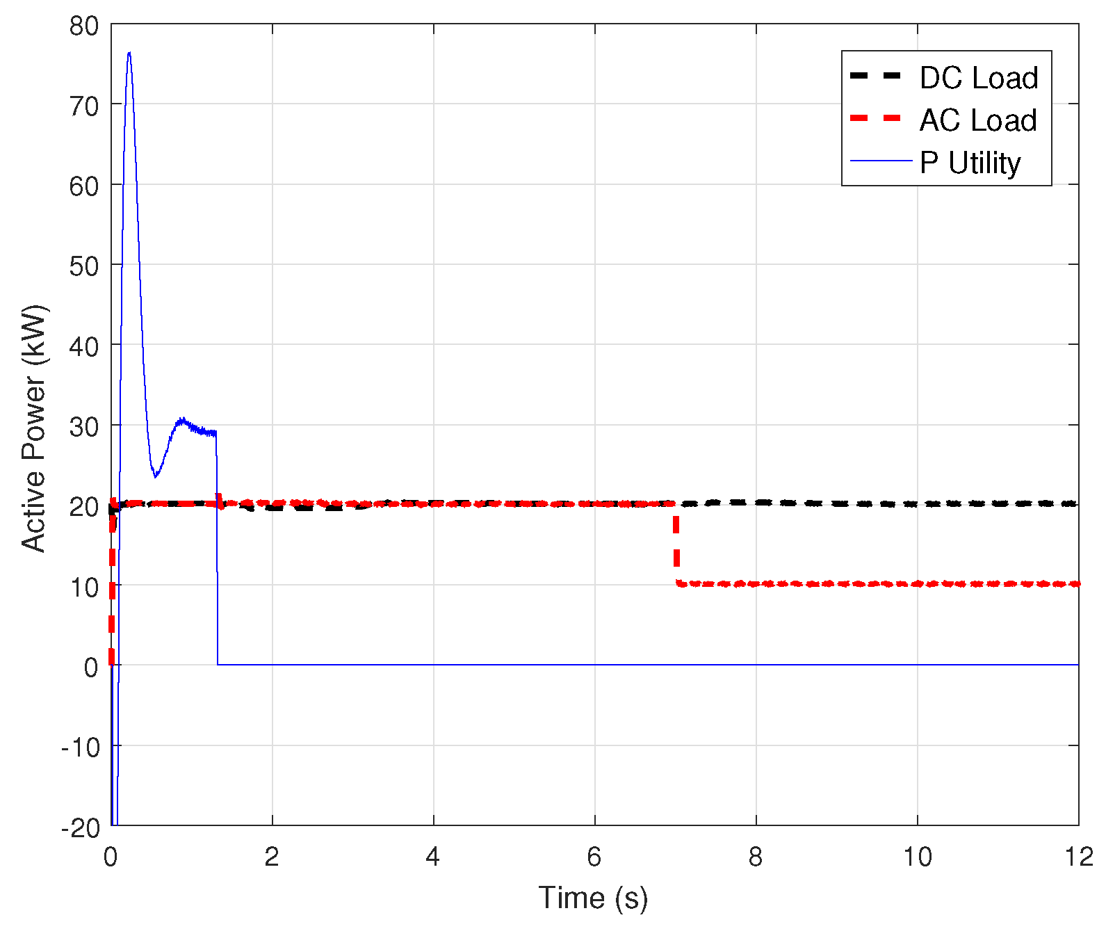
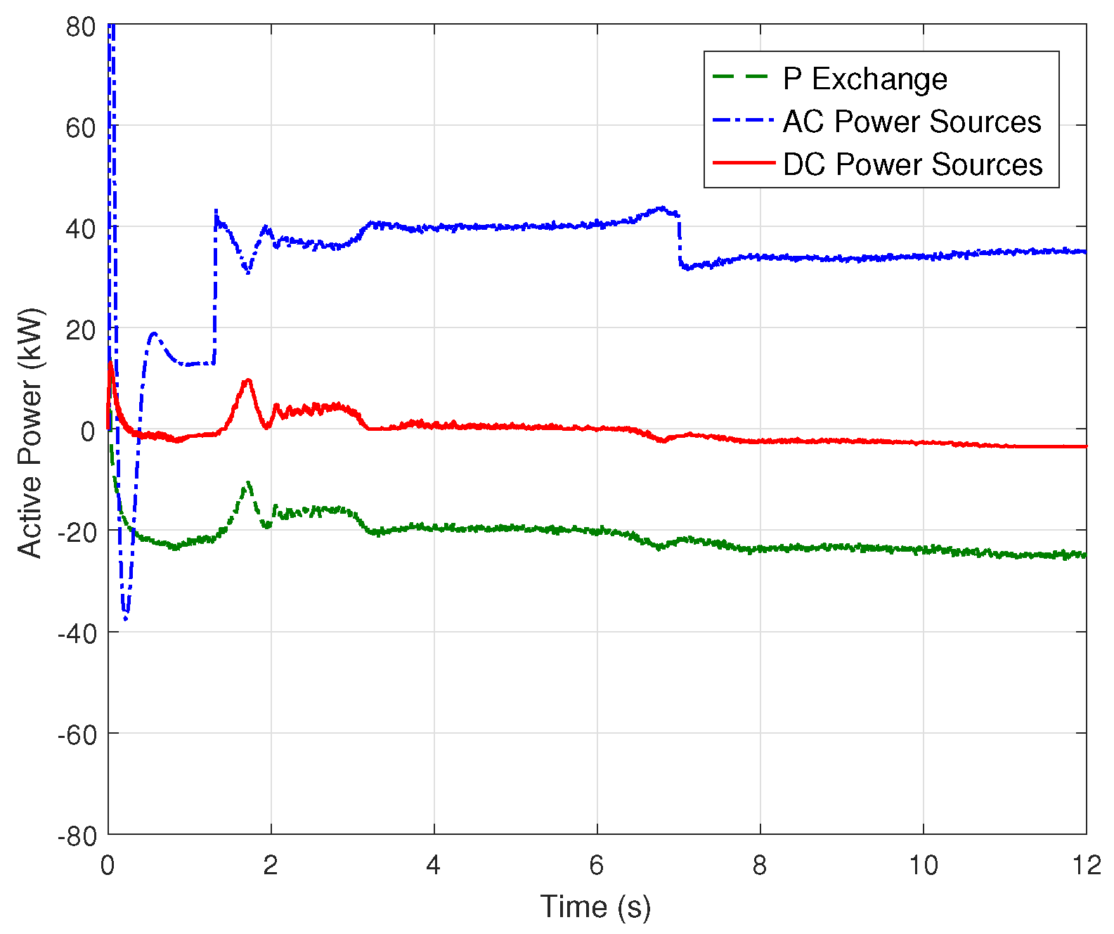
The second case investigates the system when DC power source has low energy capacity. Figure 9 shows the active-load power in both sub-grids. First, the microgrid is operated in a grid-connected mode with a constant 20 kW load in each sub-grid. Besides, the battery has low SOC (Figure 10). Figure 11 shows the resulting active power in this case. Due to the DC power source’s inability to fulfill the demand in DC grid, the utility grid acts as the main power supply for AC and DC loads. About 21 kW power is transferred from AC grid for the first 1.3 s. Thus, the battery charges slightly when the utility grid is connected to the system. As shown in Figure 12, frequency decreased as the operation mode is changed into a stand-alone mode. Thus, it causes DC voltage deviation. Since the utility grid is no longer connected to the system, the battery is discharged. In addition, the AC power sources increase its generated power to manage the power supply–demand balance in AC grid by giving a 20 kW power to the DC grid. Frequency and DC voltage are restored to their nominal value in the steady state.
Furthermore, at s, the AC load is decreased to 10 kW (Figure 9). Hence, a surplus power exists in AC sub-grid and the frequency increases from its nominal value. To restore the frequency to its nominal value, the power exchange from AC to DC grid is increased to 3 kW. As shown in Figure 10, the remaining power in DC grid is used to charge the battery. From the first and the second case, it is verified that the proposed method works well when the imbalance occurs when in AC or DC side. Moreover, the proposed method successfully manages the balance supply–demand power when the load is changed.
Next, the proposed control performance is compared to the existing current control, LQR method [17]. Similar to the the previous simulations, unknown filter parameters are used in the hybrid AC/DC microgrid. Suppose that step load is added in AC sub-grid and causes the frequency deviation. The responses from both controllers are given in Figure 13. As shown in Figure 13c, the both controllers successfully restore the frequency to its nominal value and have equivalent performance. However, comparing the current output in Figure 13a,b, the LQR method shows increasing circulating current at s. Meanwhile, the proposed method shows a consistent performance. This result is unexpected since, in [17], the LQR method demonstrated a good resulting current under a high load perturbation. However, in that case, the filter parameters are known by the controller. Thus, it is verified that the proposed method enhances the robustness of the current control against unknown system parameters.
6. Conclusions
In this paper, a hybrid AC/DC microgrid is studied. An interlink converter (IC) interfaces the AC and DC sub-grids and allows a bidirectional power exchange between them. Thus, an IC controller is required to generate a proper power exchange and maintain the AC frequency and terminal voltages in grid-connected and stand-alone operating modes. An RC or RL filter is connected to the IC to eliminate the harmonics of voltage and current output. Due to manufacturing and temperature effect, those values might be changed from their designed values and can be unknown by the controller. This paper investigates an IC controller to tackle this problem. By implementing a Linear Matrix Inequalities (LMI)-based current control for the IC, the IC can successfully manage the power–demand balance in AC and DC sub-grids under numerous unknown filter parameters. In addition, the simulation result indicates that the proposed method has better performance by maintaining the current output during high load variation, compared to the existing Linear Quadratic Regulator-based method.
Author Contributions
I.R.F. surveyed the backgrounds of this research, designed the control strategies, and performed the simulations to show the benefits of the proposed method. J.-S.K. and H.S. supervised and supported this study.
Acknowledgments
This work was supported by the Human Resources Development of the Korea Institute of Energy Technology Evaluation and Planning (KETEP) grant funded by the Ministry of Trade, Industry & Energy of the Korea government (No. 20154030200720), and by Basic Science Research Program through the National Research Foundation of Korea (NRF) funded by the Ministry of Education (NRF-2015R1D1A1A0106 0588).
Conflicts of Interest
The authors declare no conflict of interest.
Appendix A. Proof of Theorem 1
The LMI in Theorem 1 is comprised of two parts: robust stability and robust performance. Consider a quadratic Lyapunov equation where . The system in Equation (11) with a state feedback control is stable if and only if
where with and , thus . Let us fix K, then for any , the inequality in Equation (A1) can be rewritten as
Then, this is equivalent to its Schur complement inequality:
Since P is positive definite, by multiplying from left the first inequality with , and then multiplying it from right by Equation (A2) with , we obtain:
The inequality in Equation (A3) is satisfied if only if holds for all i. In a result, the closed-loop system with K is robustly stable.
Furthermore, to consider robust performance, consider the sum of Lyapunov difference in Equation (A1):
which is equivalent to
where denotes the optimal cost over the infinite horizon. Since the control input is stabilizing, it holds . Hence, it follows , which implies is an unper bound of the LQR cost. Denoting as the upper bound of , we can obtain
which corresponds to the second part of the LMI in Theorem 1. In view of the optimization problem in Theorem 1, the controller tries to minimize . Hence, the proposed control in Equation (14) robustly stabilizes the uncertain system and is suboptimal since it minimizes the upper bound of .
References
- Pogaku, N.; Prodanovic, M.; Green, T.C. Modeling analysis and testing of autonomous operation of an inverter-based microgrid. IEEE Trans. Power Electron. 2007, 22, 613–625. [Google Scholar] [CrossRef]
- Eghtedarpour, N.; Farjah, E. Power Control and Management in a Hybrid AC/DC Microgrid. IEEE Trans. Smart Grid 2014, 5, 1494–1505. [Google Scholar] [CrossRef]
- Hatziargyriou, N. (Ed.) Microgrids; John Wiley and Sons Ltd.: Chichester, UK, 2013. [Google Scholar]
- Mahmoud, S.; AL-Sunni, F.M. Control and Optimization of Distributed Generation Systems; Springer International Publishing: Cham, Switzerland, 2015. [Google Scholar]
- Loh, P.C.; Li, D.; Chai, Y.K.; Blaabjerg, F. Autonomous Operation of Hybrid Microgrid With AC and DC Subgrids. IEEE Trans. Power Electron. 2013, 28, 2214–2223. [Google Scholar] [CrossRef]
- Baharizadeh, M.; Karshenas, H.R.; Guerrero, J.M. Control strategy of interlinking converters as the key segment of hybrid AC-DC microgrids. IET Gener. Transm. Distrib. 2016, 10, 1671–1681. [Google Scholar] [CrossRef]
- Varajão, D.; Araújo, R.E.; Miranda, L.M.; Lopes, J.P.; Weise, N.D. Control of an isolated single-phase bidirectional AC-DC matrix converter for V2G applications. Electr. Power Syst. Res. 2017, 149, 19–29. [Google Scholar] [CrossRef]
- Suhara, E.M.; Nandakumar, M.; Mathew, K. Novel adaptive hysteresis current control of bidirectional three-phase PWM converter under reduced switching scheme. In Proceedings of the 2016 IEEE International Conference on Power Electronics, Drives and Energy Systems (PEDES), Trivandrum, India, 14–17 December 2016; pp. 1–6. [Google Scholar]
- Akter, M.P.; Mekhilef, S.; Tan, N.M.L.; Akagi, H. Model Predictive Control of Bidirectional AC-DC Converter for Energy Storage System. J. Electr. Eng. Technol. 2015, 10, 165–175. [Google Scholar] [CrossRef]
- Jin, N.; Hu, S.; Gan, C.; Ling, Z. Finite States Model Predictive Control for Fault-Tolerant Operation of a Three-Phase Bidirectional AC/DC Converter Under Unbalanced Grid Voltages. IEEE Trans. Ind. Electron. 2018, 65, 819–829. [Google Scholar] [CrossRef]
- Dehkordi, N.M.; Sadati, N.; Hamzeh, M. Robust backstepping control of an interlink converter in a hybrid AC/DC microgrid based on feedback linearisation method. Int. J. Control 2017, 90, 1990–2004. [Google Scholar] [CrossRef]
- Li, P.; Yan, S.; Yu, X.; Zhang, J. The H-∞ control method of the bidirectional converter in hybrid AC/DC microgrid. In Proceedings of the 2016 IEEE Power and Energy Society General Meeting (PESGM), Boston, MA, USA, 17–21 July 2016; pp. 1–5. [Google Scholar]
- Su, S.F.; Hsueh, Y.C.; Tseng, C.P.; Chen, S.S.; Lin, Y.S. Direct Adaptive Fuzzy Sliding Mode Control for Under-actuated Uncertain Systems. Int. J. Fuzzy Logic Intell. Syst. 2015, 15, 240–250. [Google Scholar] [CrossRef]
- Chung, G.-B. Takagi-Sugeno Fuzzy Integral Control for Asymmetric Half-Bridge DC/DC Converter. Int. J. Fuzzy Logic Intell. Syst. 2007, 7, 77–84. [Google Scholar] [CrossRef]
- Lim, J.S.; Park, C.; Han, J.; Lee, Y.I. Robust Tracking Control of a Three-Phase DC AC Inverter for UPS Applications. IEEE Trans. Ind. Electron. 2014, 61, 4142–4151. [Google Scholar] [CrossRef]
- Maccari, L.A.; Massing, J.R.; Schuch, L.; Rech, C.; Pinheiro, H.; Oliveira, R.C.; Montagner, V.F. LMI-Based Control for Grid-Connected Converters With LCL Filters Under Uncertain Parameters. IEEE Trans. Power Electron. 2014, 29, 3776–3785. [Google Scholar] [CrossRef]
- Aryani, D.R.; Kim, J.-S.; Song, H. Interlink Converter with Linear Quadratic Regulator Based Current Control for Hybrid AC/DC Microgrid. Energies 2017, 10, 1799. [Google Scholar] [CrossRef]
- Brian, D.; Andersen, O.; Moore, J.B. Optimal Control: Linear Quadratic Methods; Prentice Hall: London, UK, 1989. [Google Scholar]
- Boyd, S.; El Ghaoui, L.; Feron, E.; Balakrishnan, V. Linear Matrix Inequalities in System and Control Theory. In SIAM Studies in Applied Mathematics; SIAM: Philadelphia, PA, USA, 1994. [Google Scholar] [Green Version]
- Anderson, B.D.; Moore, J.B. Optimal Control: Linear Quadratic Methods; Prentice Hall: Englewood Cliffs, NJ, USA, 1989. [Google Scholar]
- Weinert, H. Bryson, A. E./Ho, Y.-C., Applied Optimal Control, Optimization, Estimation, and Control. New York-London-Sydney-Toronto; John Wiley & Sons: Hoboken, NJ, USA, 1975. [Google Scholar]
Figure 1.
Hybrid AC/DC Microgrid.

Figure 2.
Block diagram of IC controller.

Figure 3.
AC microgrid characteristic.

Figure 4.
RL filter is used in the IC.

Figure 5.
Conventional current control based on PI controller.

Figure 6.
Proposed interlink converter (IC) controller.

Figure 7.
Power flow for the first case: (a) AC active power; (b) reactive power; and (c) DC active power.
Figure 7.
Power flow for the first case: (a) AC active power; (b) reactive power; and (c) DC active power.

Figure 8.
Response for the first case: (a) DC Voltage; and (b) AC Frequency.

Figure 9.
Load variation in the second case simulation.

Figure 10.
Resulting SOC for the second case.

Figure 11.
Resulting active power flow for the second case.

Figure 12.
Response for the second case: (a) frequency; and (b) DC Voltage.

Figure 13.
Simulation results using LQR and LMI-based LQR methods in high load variation. Despite the resulting frequency of both methods are equivalent, however, in terms of current output, the LMI-based LQR is more robust compared to the LQR method.
Figure 13.
Simulation results using LQR and LMI-based LQR methods in high load variation. Despite the resulting frequency of both methods are equivalent, however, in terms of current output, the LMI-based LQR is more robust compared to the LQR method.


Table 1.
Simulation parameters.
| Parameters | Value |
|---|---|
| AC Frequency | 60 Hz |
| AC Voltage (rms) | 226 V |
| DC Bus Voltage | 500 V |
| IC Power Rating | 70 kW |
| Filter Inductance | 5 [0.7 1.3] mH |
| Filter Resistance | 0.1 [0.7 1.3] |
| DC link Capacitance | 10,000 F |
| Sampling Time | 20 s |
© 2018 by the authors. Licensee MDPI, Basel, Switzerland. This article is an open access article distributed under the terms and conditions of the Creative Commons Attribution (CC BY) license (http://creativecommons.org/licenses/by/4.0/).
Share and Cite
MDPI and ACS Style
Fitri, I.R.; Kim, J.-S.; Song, H. A Robust Suboptimal Current Control of an Interlink Converter for a Hybrid AC/DC Microgrid. Energies 2018, 11, 1382. https://doi.org/10.3390/en11061382
AMA Style
Fitri IR, Kim J-S, Song H. A Robust Suboptimal Current Control of an Interlink Converter for a Hybrid AC/DC Microgrid. Energies. 2018; 11(6):1382. https://doi.org/10.3390/en11061382
Chicago/Turabian StyleFitri, Ismi Rosyiana, Jung-Su Kim, and Hwachang Song. 2018. "A Robust Suboptimal Current Control of an Interlink Converter for a Hybrid AC/DC Microgrid" Energies 11, no. 6: 1382. https://doi.org/10.3390/en11061382
Note that from the first issue of 2016, this journal uses article numbers instead of page numbers. See further details here.