1. Introduction
Heat transfer from a cavity has been investigated in many engineering sciences due to its various applications. Some of these applications include building insulation, electrical appliances, cooling and designing heat exchangers and HVAC.
The interaction of convection and conduction heat transfer in a cavity in which the fluid and solid phases are in close contact is referred to as the conjugate convection heat transfer [
1]. Vahl Davis [
2], Turan et al. [
3], Deng and Tang [
4], and Sathiyamoorthy and Chamkha [
5] have examined the natural convection heat transfer in a closed square cavity. They found that heat transfer is under the strong influence of the Rayleigh number.
Nanofluids are stable suspensions of nanoparticles and a base fluid. Nanofluids have shown enhanced heat transfer properties, and various aspects of heat transfer in nanofluids have been explored in excellent reviews by Devendiran and Amirtham [
6], Kumar et al. [
7] and Verma and Tiwari [
8]. Hybrid nanofluids are a new type of nanofluids which consist of two types of nanoparticles stably dispersed in the base fluid. The nanoparticles in the base fluid shape composite nanoparticles. Hybrid nanofluids enjoy the advantages of two types of nanoparticles. Considering hybrid nanofluids, Sarkar et al. [
9], Sundar et al. [
10], and Sidik [
11] have presented excellent reviews on the thermophysical properties and applications of hybrid nanofluids.
Heat transfer in porous media has been the subject of many recent studies, and various aspects of heat transfer in porous media have been explored in the literature. There are many cases in which a porous medium can be treated as a local thermal equilibrium. In such a model, there are no temperature differences between the porous matrix and the fluid inside the pores. This assumption is true for media with small porosities such as geothermal reservoirs and thermal insulators. However, if the porous matrix and the fluid do not have the same temperature for any reason such as heat generation in the porous matrix, the porous medium and the fluid should be treated as the thermal non-equilibrium. The thermal equilibrium cannot be assumed for the porous media with materials of the metallic porous matrix with very high thermal conductivity or media in which heat is generated in one of the solid or fluid phases.
Most of the previous studies have addressed flow and heat transfer in porous media by considering the thermal equilibrium model. Baytas et al. [
12] studied the free convection in a porous cavity. They focused on the role of the thermal conductivity of horizontal walls in heat transfer and fluid flow. The results reported by Baytas et al. indicated that the temperature of the fluid-horizontal wall interface decreases with the increase in the thermal conductivity. Baytas et al. [
13] examined the free convection heat transfer in a typical cavity containing heat-generating fluid. They found that the height of the step at the interface induces a significant effect on the flow field and heat and mass transfer from the left-hand to the right-hand walls. Additionally, in certain cases, the results obtained by these authors were very well in line with the results obtained by other researchers. Wei et al. [
14] investigated the solid-liquid phase change heat transfer in the presence of convection heat transfer in a porous medium using a lattice Boltzmann model. The results showed that the temperature and heat flux continuity conditions at the interface between phases of different thermos-physical properties were inherently satisfied for the model. Chen [
15] investigated the lattice Boltzmann model for heat transfer in the porous media. The purpose of this study was to provide a new numerical solution to remedy the shortcomings of previous models. Gao et al. [
16] investigated the modified lattice Boltzmann model for conjugate heat transfer in porous media. The numerical results of Gao et al. [
16] were in a very good agreement with the analytical and numerical solutions reported in previous studies. The authors argued that the proposed model can be used as a feasible tool for conjugate heat transfer problems in porous media. Miroshnichenko et al. [
17] modeled the flow and heat transfer of alumina nanofluids in a cavity composed of two layers of porous media and two layers of clear flows. The outcomes indicated that the thickness of the porous layers and clear layers plays an important role in enhancing heat transfer in the cavity. Dogonchi et al. [
18] investigated the MHD natural convection of Cu–water nanofluid in a gap between hot rectangular-cylinder and a cold circular-cylinder filled with porous medium.
Ghalambaz et al. [
19] studied the natural convective heat and mass transfer of nanofluid over a vertical plate embedded in a Darcy porous medium that was exposed to the hot surface and the flux of nanoparticles. They found that the rise of the Eckert number (viscous dissipation effects) decreases the Nusselt number at the hot wall. Kasaeia et al. [
20] conducted a study entitled “Nanofluid flow and heat transfer in porous media”, where they comprehensively reviewed the simultaneous application of nanofluids and porous media for such purposes as heat transfer enhancement in thermal systems with different structures, flow regimes, and boundary conditions.
There are recent studies into the Local Thermal Non-Equilibrium (LTNE) model of heat transfer in a cavity. Izadi et al. [
21], Sheremet et al. [
22] as well as Zargartalebi et al. [
23] studied the natural convection of nanofluids in enclosures. Izadi et al. [
24] also studied the MHD flow of CuO-water nanofluid in an enclosure by considering a geothermal viscosity model. The outcomes revealed that a raise in the viscosity-parameters results in the improvement of the heat transfer and convective flow intensification. Hashemi et al. [
25] investigated the effect of using micropolar nanofluids in a porous medium cavity.
Considering the conjugate natural convection heat transfer and LTNE porous medium, there is a bifurcation heat flux channel at the interfacial layer. A portion of the conjugate heat flux enters the porous matrix and another portion enters the fluid inside the porous pores. Therefore, the study of conjugate natural convection heat transfer in enclosures is a very interesting heat transfer phenomenon which demands future investigation.
Very recently, Mehryan et al. [
26] and Zargartalebi et al. [
27] have addressed the conjugate natural convection of nanofluids in a cavity considering a LTNE model of porous medial for the case of nanofluids with only one type of nanoparticles. The present study aims to LTNE heat transfer of hybrid nanofluids which consist two type of nanoparticles. The review of the literature shows that the results of the present study are new and have not been addressed yet. The present research tends to answers the following fundamental questions regarding the natural convection flow and heat transfer of hybrid nanofluids:
- (1)
Does using hybrid nanofluids enhance free convection in a cavity?
- (2)
What are the effects of using porous space and solid blocks on the performance of hybrid nanofluids?
- (3)
How do the volume fraction of hybrid nanoparticles and the buoyancy effects (Rayleigh number) change the thermal performance of hybrid nanofluids?
2. Mathematica Model
Consider a square cavity partially filled with three regions of clear flow filled with a hybrid nanofluid, a porous medium saturated with the hybrid nanofluid and a thermal conductive solid block.
Figure 1 shows a schematic view of the physical model and the coordinate system.
According to the figure, the cavity is a two-dimensional square with sides of length L. The bottom and top horizontal walls of the closed cavity have been kept at hot temperature Th and the cold temperature Tc, respectively with Th ˃ Tc. In addition, the left and right vertical walls of the cavity are insulated. The height of the porous region and the solid block is w while the length of the solid block is d. The hybrid nanofluid is under the influence of the gravitational acceleration g which acts in the opposite direction of the vertical axis (y). It is also assumed that the hybrid nanofluid is Newtonian and incompressible. The flow is laminar in the clear region, and Darcy-Brinkman model is applied for the porous domain region. The buoyancy effects are modeled using the Boussinesq approximation. It is assumed that the surface of porous structure is treated using charges techniques or other methods in a way that the nanoparticles cannot deposit at the solid surface.
2.1. The Governing Equations for the Nanofluid
The governing equations for the fluid phase include the continuity equation, the equations of momentum in the horizontal direction, momentum in the vertical direction, and energy. The flow function is also added to these equations, so, for the fluid, we will have:
where
u is the horizontal component of the fluid velocity,
v is the vertical component of the fluid velocity,
x and
y are the vertical and horizontal components of the location, respectively,
ρhnf is the nanofluid density,
g is the gravitational acceleration and
p is pressure. In addition,
Thnf is the nanofluid temperature,
μhnf is the dynamic viscosity,
khnf is the thermal conductivity of the nanofluid,
cphnf is the thermal capacity of the nanofluid.
2.2. Governing Equations for the Porous Medium
According to the problem definition, the cavity containes a porous medium. This necessitates the definition of equations related to the porous medium. For this purpose, the continuity equation, the equations of momentum in the horizontal direction, momentum in the vertical direction, the fluid energy, and the solid energy in the porous medium will be as follows:
where
Ts is the solid medium temperature in the porous medium and
ε is the porosity coefficient. In addition, the flow stream function for the clear fluid and the fluid inside the porous medium can be defined as follows:
where
Ψ is the nanofluid flow function.
2.3. Governing Equations for the Solid Medium
As already mentioned, the hot wall is thick and will be considered as a solid medium. For this purpose, the given medium will only include an energy equation. Therefore, we will have:
where
Tw is the temperature in the solid medium,
x and
y are the horizontal and vertical components of the location, respectively.
2.4. Boundary Conditions
2.4.1. The Bounded Walls of the Cavity
The
u and
v velocities on solid walls:
where
T is the temperature,
u is the horizontal component of velocity,
v is the vertical component of the velocity,
x and y are respectively the horizontal and vertical components of the location, and
L is the cavity length.
2.4.2. The Porous Medium and Clear Flow Interface
The boundary condition of porous-clear flow has been studied in [
28,
29]. In the present study, the continuity of velocity and tension at the interface is considered. In addition, assuming that the heat transfer between the fluid/nanofluid and the porous medium matrix is large enough, the temperature is assumed to be equal at the interface between the fluid/nanofluid and the porous medium matrix. Therefore, the boundary conditions are the interface of the porous and nanofluid introduced as:
where
khnf,eff =
ε ×
khnf and
ks,eff = (1−
ε)
ks and
μhnf,eff =
μhnf/ε.
2.4.3. The Porous Medium and Solid Block
Introducing a proper boundary condition at the interface between the porous medium and the solid conductive wall has been a challenging issue. This type of boundary condition for porous-solid wall interface has been previously discussed in some excellent works [
30,
31,
32,
33]. In the present study the non-slip and non-penetration conditions are established for the velocity at the interface between the porous medium and the solid medium. Considering the continuity of temperature and energy balance at the interface, the thermal boundary conditions at the interface of the porous medium and solid wall are introduced as:
where
kw is the thermal conductivity of the wall and
Tw is the temperature of the wall.
2.4.4. The Clear Flow and Solid Block
The no-slip and no permeability of solid wall are adopted for the fluid flow. The continuity of temperature and heat is used for the thermal boundary condition as:
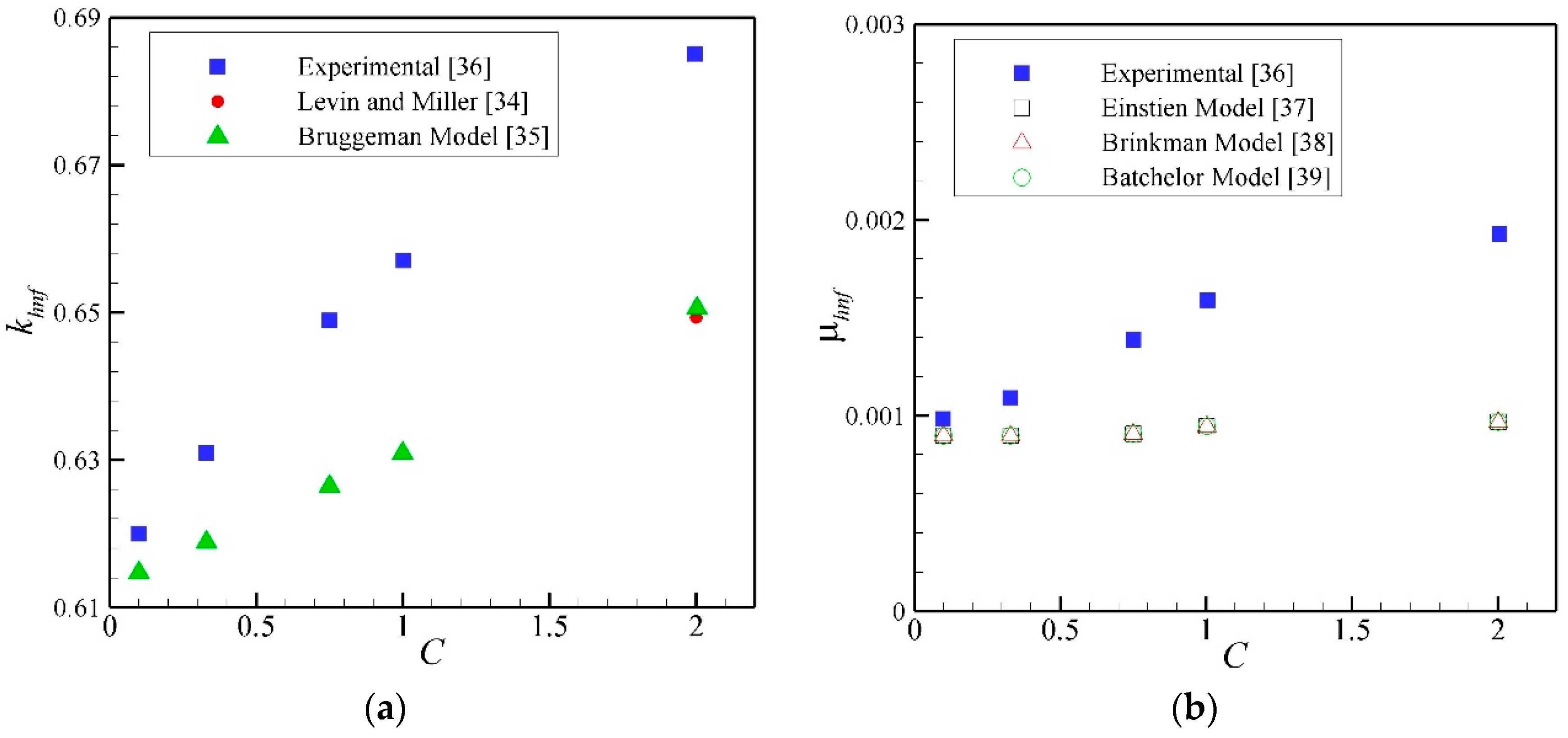
2.5. Thermophysical Properties
Here, several models of thermal conductivity and dynamic viscosity of nanofluids are utilized and the results are plotted in
Figure 2.
The Levin and Miller [
34] and Bruggman [
35] models are adopted for the prediction of thermal conductivity of the Al
2O
3-Cu / water hybrid nanofluid and the results are presented in
Figure 2a. The experimental data in [
36] have been used as a comparison reference. Considering the dynamic viscosity, the Einstein model [
37], Brinkman model [
38] and Batchelor model [
39] are utilized for the prediction of dynamic viscosity. The experimental results in [
36] have also been utilized as a reference comparison. As can be seen, the dynamic viscosity and thermal conductivity of the hybrid nanofluid cannot be predicted properly using the available models. Hence, the experimental data in [
36] have been directly utilized for the convection heat transfer analysis of the present study. The experimental results in [
36] for dynamic viscosity and thermal conductivity are summarized in
Table 1. The hybrid nanofluid sample in [
36] was obtained using the hydrogen-reduction technique from a powder mixture containing 90% of alumina and 10% of copper oxide. Based on [
36], using ultrasonic and a two-step synthesis method, a stable and uniform suspension of hybrid nanofluids of Al
2O
3/Cu water with 0.1–2% volume fraction of nanoparticles was prepared. The thermal conductivity of the nanofluid in the present study is directly extracted from
Table 1.
The density and thermal capacity of the hybrid nanofluid are evaluated using the following equations [
40]:
The thermal expansion of the hybrid nanofluid is evaluated using:
Finally, the effective thermal conductivity of the porous medium and the liquid inside the pores can be obtained according to the method described in [
41].
2.6. Non-Dimensional form of Governing Equations
Here, the base fluid thermophysical properties are utilized to transform the governing equations into a general non-dimensional form. In order to achieve the non-dimensional form of the equations, the following form of the non-dimensional parameters is adopted:
where
X,
Y,
D,
W,
U,
V,
Ψ,
P,
θ are respectively the non-dimensional expression of the horizontal position of location, the vertical position of location, the non-dimensional width of the solid medium, the non-dimensional width of the porous medium, the velocity component along
x direction, the velocity component along
y direction, the flow, pressure, and temperature functions.
θhnf is the non-dimensional temperature of hybrid nanofluid,
θs is the non-dimensional temperature of porous matrix, and
θw is the non-dimensional temperature of wall. In addition,
Da, Pr,
Ra are Darcy, Prandtl, and Rayleigh numbers.
H,
kr, and
Rk are also the permeability coefficient of the porous medium, the conductivity ratio coefficient of the porous material and the thermal conductivity ratio of wall-to-fluid. On the other hand, Δ
T is the temperature difference between the hot and cold walls, which is defined as Δ
T =
Th −
Tc. Now, by involving Equation (20) the governing Equations of (1) to (11) are transformed in to the following non-dimensional form.
2.6.1. Clear Flow
The non-dimensional stream function was also obtained using:
where the ratio of the effective thermal diffusivity of nanofluid to that of the base fluid is defined as:
2.6.2. Porous Medium Layer
2.7. The Non-Dimensional Boundary Conditions
The boundary conditions corresponding to the introduced governing equations are transformed into the non-dimensional form using the non-dimensional parameters and variables of Equation (20).
2.7.1. The Bounded Walls of the Cavity
The
U and
V velocities on solid walls:
2.7.2. The Porous Medium and Clear Flow Interface
2.7.3. The Porous Medium and Solid Block
2.8. Nusselt Number
The important characteristic parameter of the present study for analysis of heat transfer is the Nusselt number. The Nusselt number is generally defined as follows:
where
h is the convection heat transfer coefficient,
L is the cavity length, and
k is the thermal conductivity. Now, using the non-dimensional parameters of Equation (20) and substituting them into Equation (38), and after the simplification, the non-dimensional equation of the Nusselt number is obtained as:
To calculate the Nusselt number in the cavity, according to the schematic
Figure 1, the Equation (40) is integrated on the hot wall, so we will have:
However, it should be noted that the problem has been considered assuming the thermal non-equilibrium for the porous medium. Therefore, defining θf and θs as the non-dimensional temperature of the fluid and solid matrix respectively, the Nusselt number will be defined as follows:
The Nusselt number for fluid in the porous medium:
4. Results
In the present study, two nanoparticles of Al
2O
3 and Cu in the base fluid of water were selected as the hybrid nanofluid.
Table 4 presents the thermal and rheological properties of Al
2O
3 and Cu nanoparticles [
36], as well as water fluid. As can be seen, the conductivity (
k) of Cu is much higher than that of Al
2O
3, and adding Cu can help to overcome the drawbacks of Al
2O
3 and water and obtain a hybrid nanofluid with higher conductivity. However, due to the higher density of Cu than Al
2O
3, the dynamic viscosity of the resulting nanofluid increases, which may have negative effects. The dynamic viscosity and thermal conductivity of the hybrid nanofluid is evaluated using the actual experimental data reported in
Table 1. The data in
Table 4 are used to evaluate the other thermophysical properties such as hybrid nanofluid density or heat capacity.
The default value of the non-dimensional parameters is adopted as Ra = 106, Pr = 5, C = 1, Da = 103, H = 10, Kr = 10, Rk = 10, D = 0.5, W = 0.4, ε = 0.3 and the results of the present study are reported for these non-dimensional parameters otherwise the value will be stated.
4.1. The Effect of Hybrid Nanofluid
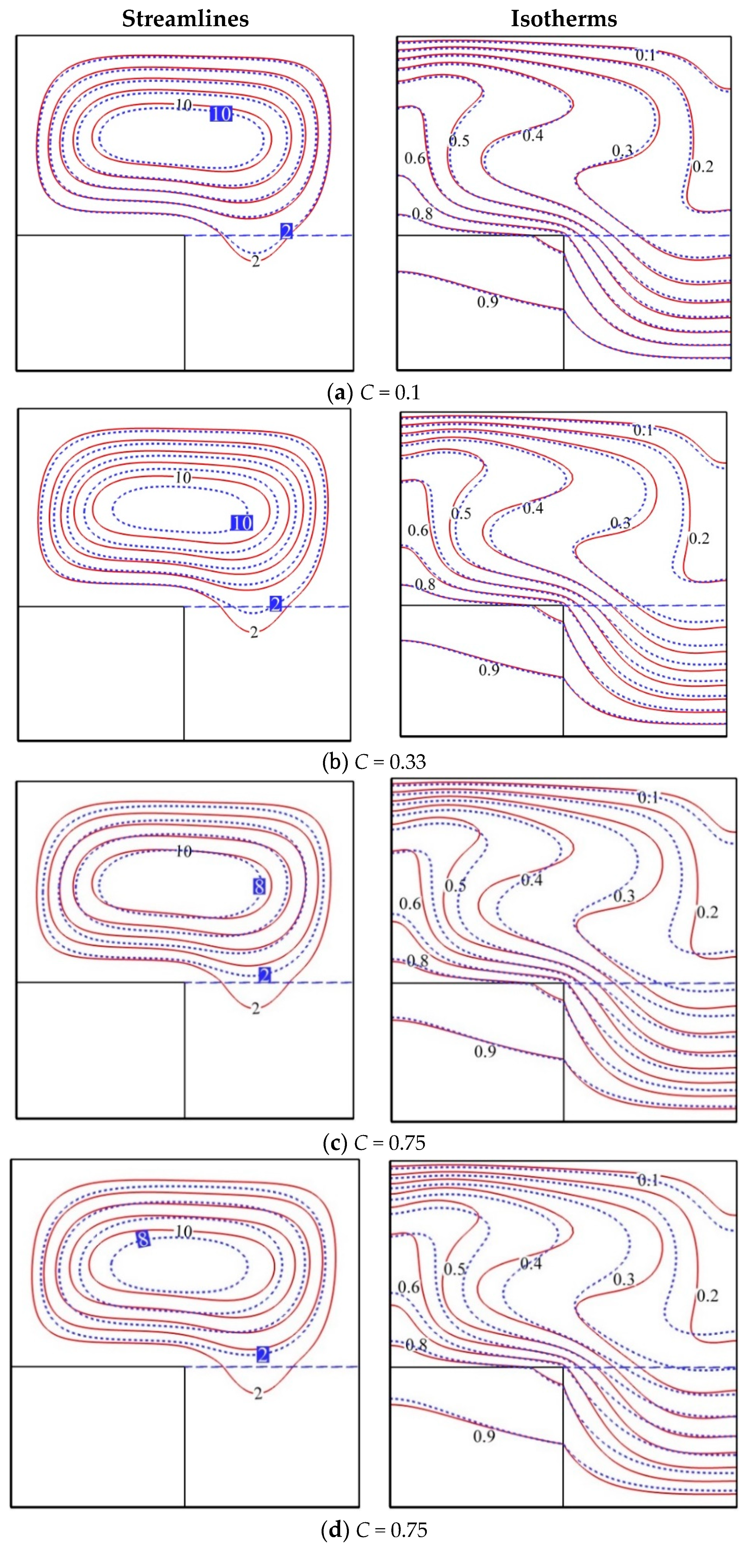
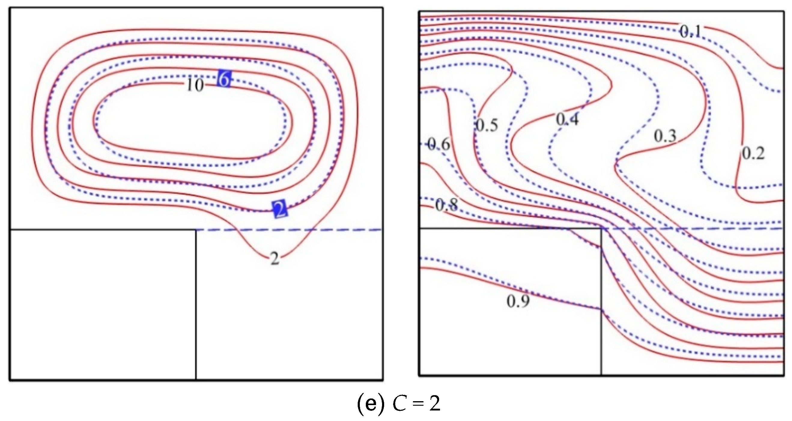
Figure 7 shows streamlines and isotherms in the cavity for different concentrations of nanoparticles (blue line) compared to pure fluid (
C = 0) (red line). In
Figure 7a, the concentration (
C) of nanoparticles is equal to 0.1%. This amount is such that the results for the stream lines and isotherms are very close to each other in the nanofluid and pure fluid. This shows the similarity of the nanofluid and pure fluid properties at this concentration. The values presented for the lowest and highest streamline in the cavity indicate the closeness of the values as well as the line profiles at this concentration. However, the isotherms show similar results. It is expected that the heat transfer at this concentration is close to the results for the pure fluid because the addition of nanoparticles has not significantly affected the fluid properties. As the concentration of the nanoparticle increases, the fluid properties also change, and the results indicate an increase in the difference between the streamline and the isotherms. By reaching a concentration (
C) of 0.33%, the flow is enhanced in the center of the cavity but its width decreases and the flow in the porous medium is weakened. Further, by increasing the concentration (
C) to 0.75, the flow in the center continues to increase and the flow is weakened in the porous medium. However, the values inserted on the lines also show a decrease in the flow rate. The decreased flow can be caused by the change in viscosity of the fluid due to the addition of nanoparticles. As the viscosity increases with the increased volume fraction of nanoparticles, the decreased flow velocity in the cavity can be expected by the increased viscosity considering its contrary relationship with the Rayleigh number. This certainly affects heat transfer, as discussed below. By increasing the concentration (
C) to 1% and then 2%, the streamlines are merged at the center of the cavity. On the other hand, the change in the flow regime also changes the profile of the isotherms.
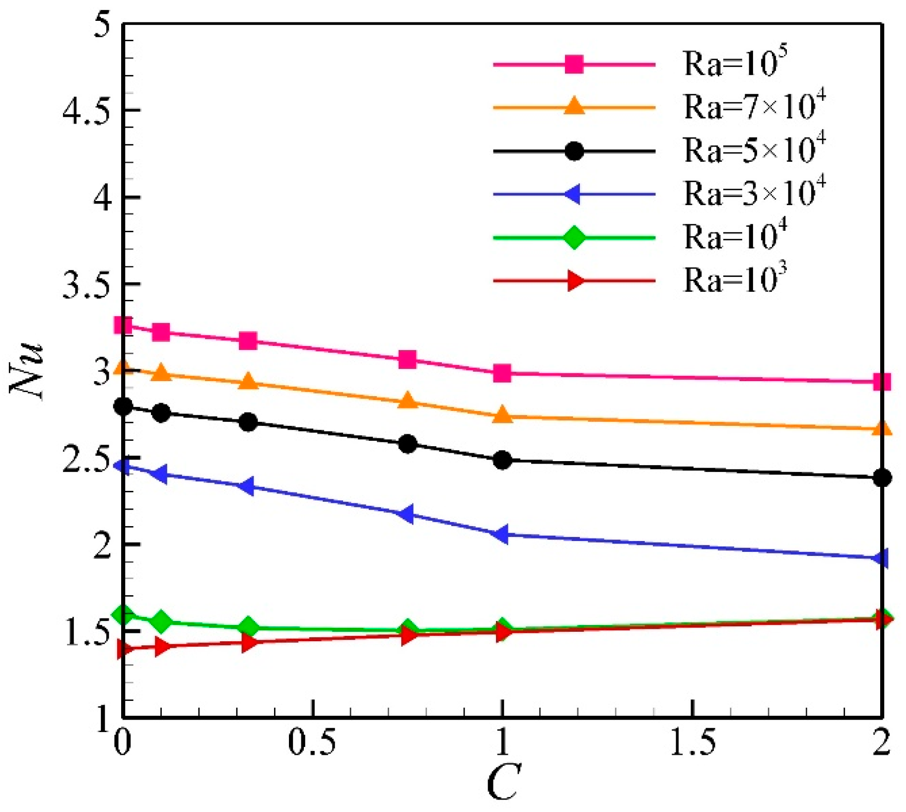
Figure 8 shows the Nusselt number as a function of different concentrations of nanoparticles for different Rayleigh numbers.
Figure 8 shows that the addition of nanoparticles reduces heat transfer in all Rayleigh numbers, except the Rayleigh numbers (
Ra) lower than 10
4. It should be noted that the addition of nanoparticles changes the two effective parameters; first, thermal conductivity and second, dynamic viscosity. Both parameters increase with increased concentration. Now, it should be considered that the effect of the increase in which one takes over that of the other, while the increased thermal conductivity increases the heat transfer capacity and the increased dynamic viscosity decreases the heat transfer capacity. The results from
Figure 8 indicate that the effect of increased dynamic viscosity takes over the effect of increased thermal conductivity in all Rayleigh numbers, except lower ones, resulting in decreased heat transfer. However, in lower Rayleigh numbers, the effect of increased thermal conductivity takes over the effect of increased dynamic viscosity resulting in enhanced heat transfer.
4.2. The Effect of Darcy Number (Da)
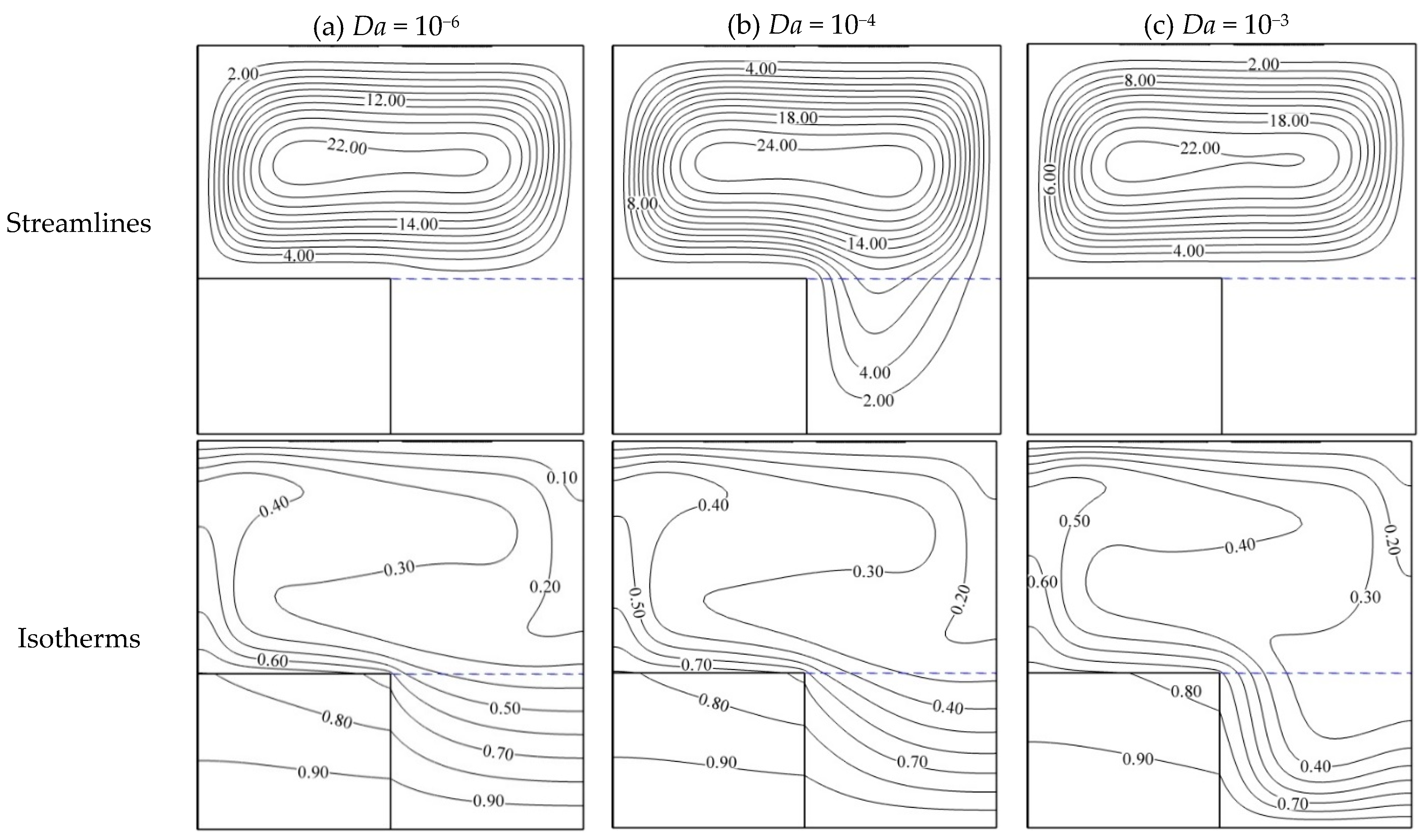
Figure 9 shows the effect of the Darcy number on the streamline and isotherms. In
Figure 9a, the Darcy number (
Da) is equal to 10
−6, indicating a low permeability coefficient for the porous medium. Therefore, the penetration and movement of the nanofluid in the porous matrix is limited and no constant streamline can be seen in the figure related to the streamline lines in the porous medium. However, this does not mean the absence of the nanofluid. Rather, it means a slow flow. On the other hand, the isotherms in
Figure 9a are almost horizontal due to the negligible fluid motion, indicating the negligible amount of the nanofluid flow in the porous medium and the lack of strength of the nanofluid circulation in this region. In
Figure 9b, by increasing the Darcy number (
Da) to 10
−4 and increasing the permeability, the flow is enhanced in the porous region and the streamlines are also inclined partially to this region, indicating increased flow circulation in this porous region. The isotherms for the aforementioned Darcy number have also confirmed this conclusion as the isotherms have changed under the influence of the nanofluid flow. In
Figure 9c, by increasing the Darcy number (
Da) to 10
−3, the flow in the porous region is dramatically enhanced and streamlines are distributed in this region. Due to the enhancement of the nanofluid flow circulation, the isotherms have also changed and become almost vertical in the vicinity of the solid medium, indicating the enhancement of the flow and the convection mechanism in the vicinity of the solid medium.
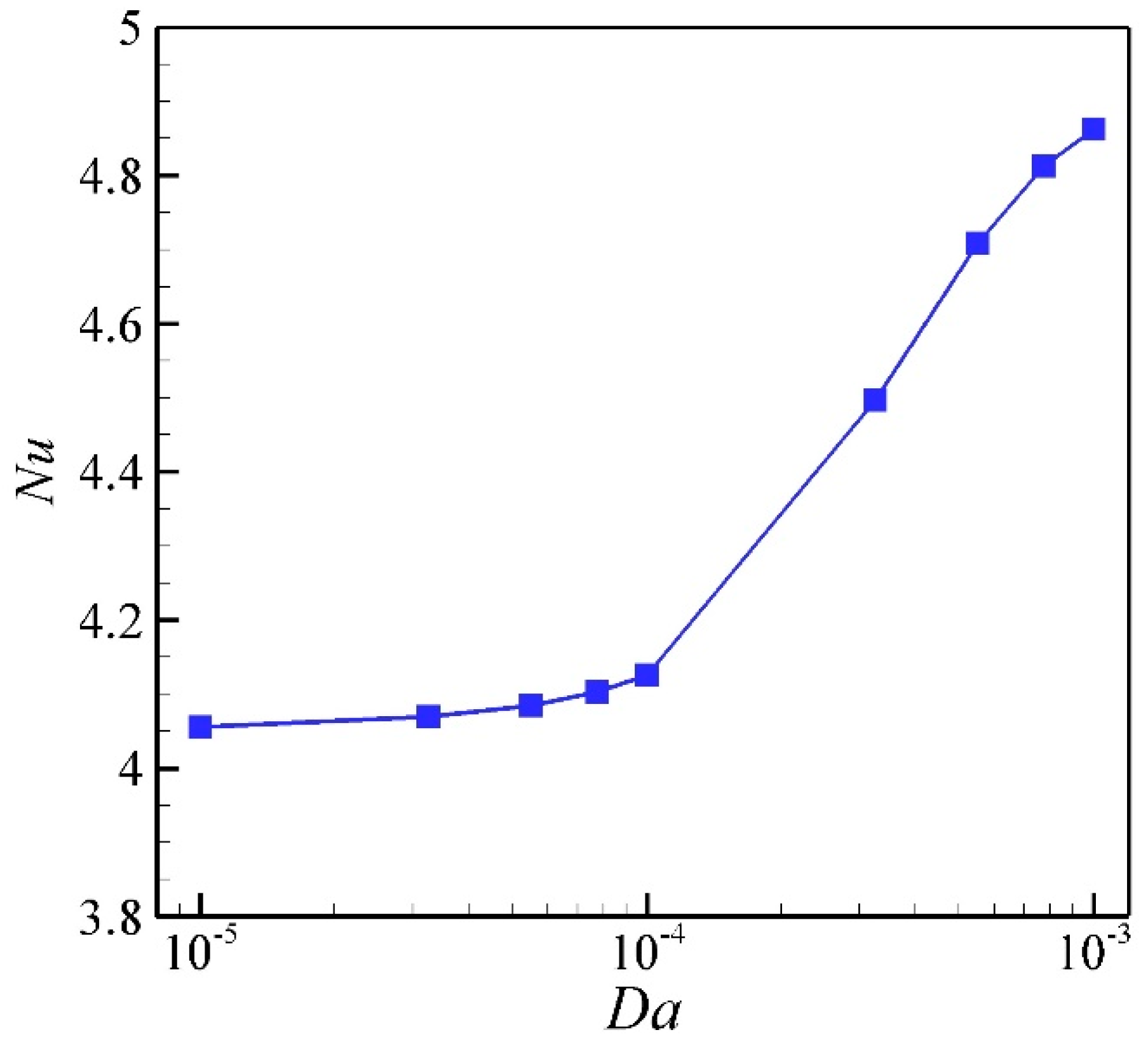
Figure 10 shows the Nusselt number for the different values of the Darcy number. According to
Figure 9, the increase in the Darcy number means increased permeability and, consequently, an increased flow in the cavity. Now, it can be seen in
Figure 10 that the hybrid nanofluid Nusselt number increases with the increase in the Darcy number, indicating increased heat transfer.
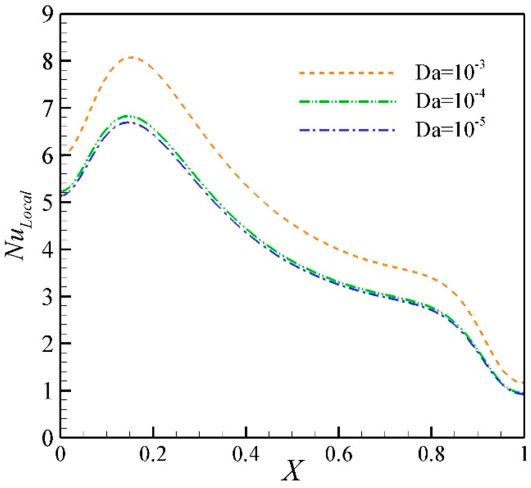
Figure 11 shows the hybrid nanofluid local Nusselt number on the cold wall for different values of the Darcy number. As explained in the previous figure (
Figure 10), an increase in the Darcy number leads to increased heat transfer. This also applies to local Nusselt and follows the same pattern. On the other hand, the profiles of the local Nusselt number are similar in different Darcy numbers; they only differ in values. In addition, the maximum local Nusselt occurs on the left side of the cold wall in about
X = 0.2, which can be seen in
Figure 11 by the high accumulation of the isotherms in this region.
4.3. The Effect of Porosity Coefficient (ε)
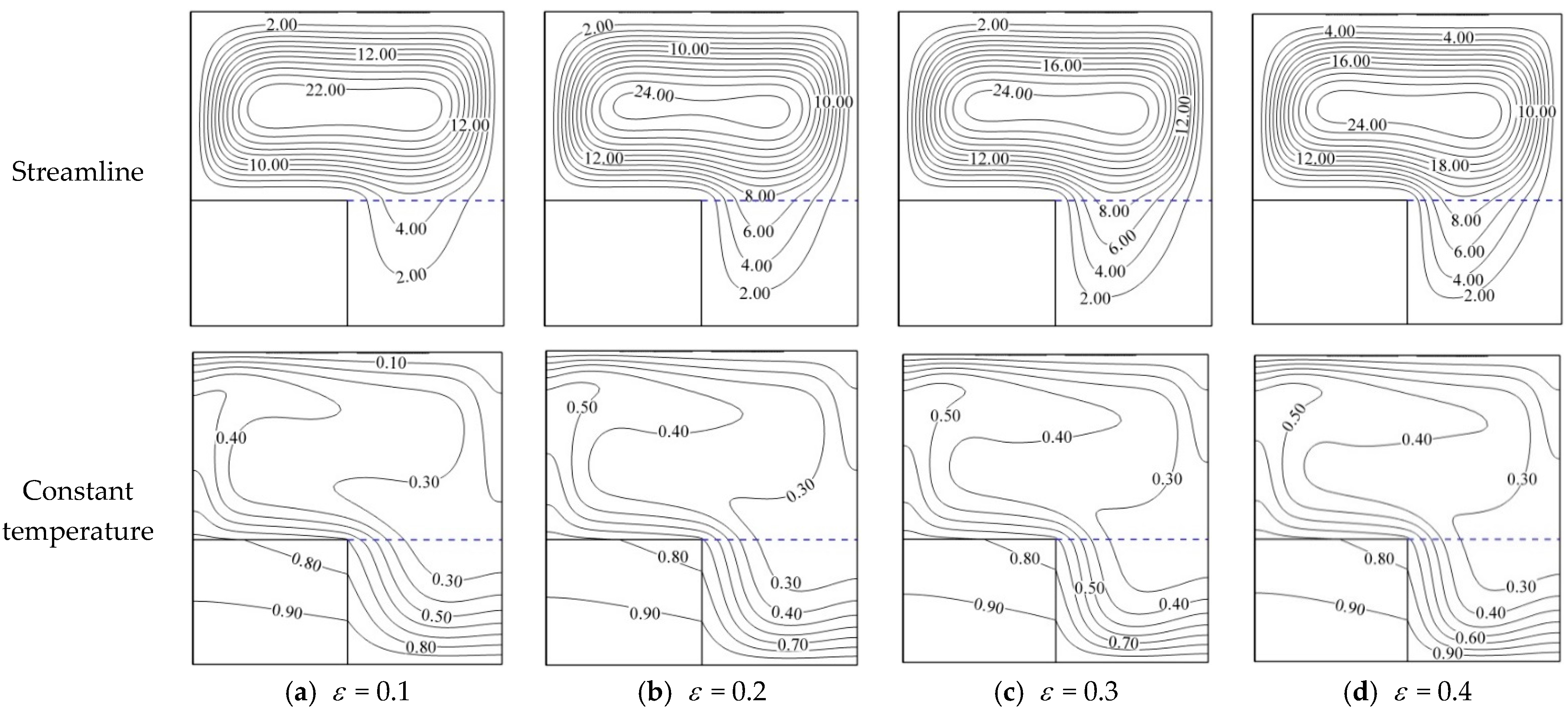
Figure 12 shows the effect of the porosity coefficient on the streamline and isotherms. In
Figure 12a, the porosity coefficient (
ε) is equal to 0.1. Due to the low amount of porosity coefficient, there is a small portion of void space to be filled with the fluid and streamline lines in the figure have a low accumulation in the porous medium. This reduces the flow circulation in the entire cavity and the isotherms in the porous medium have a low accumulation in the vicinity of the walls. By increasing the porosity, the circulation of the nanofluid flow improves gradually in the porous medium, and when the porosity (
ε) is equal to 0.4, nanofluid circulates well in the porous medium. This has led to the high accumulation of the isotherms in the vicinity of the walls. On the other hand, considering the values inserted on the streamline lines, the increased porosity has led to an increased flow.
Figure 13 shows the Nusselt number for different values of porosity coefficient. Increasing the porosity coefficient means the enhancement of the flow in the porous medium. This has been shown in
Figure 12 in the form of streamline lines. Therefore, the enhancement of flow in the cavity causes the enhanced convective mechanism and increase heat transfer.
Figure 13 demonstrates that the Nusselt number increases with increased porosity, indicating increased heat transfer in the cavity.
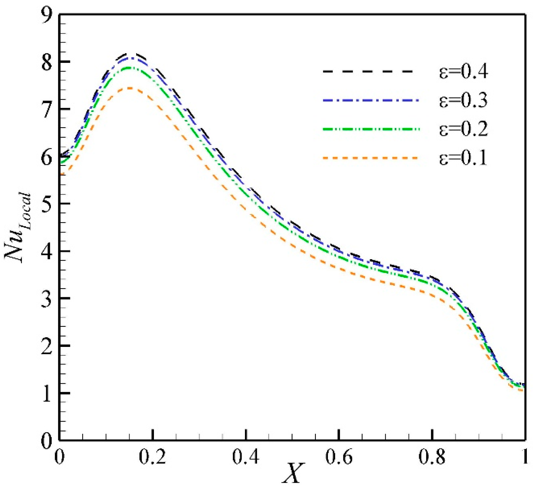
Figure 14 shows the local Nusselt number of the hybrid nanofluid on the cold wall for different values of porosity coefficient. As shown in the previous figure (
Figure 12), increasing the porosity coefficient leads to the increased heat transfer. This is also evident in the present figure and the local Nusselt number has also increased with the increase in the porosity coefficient. The profile of the local Nusselt number is also such that its maximum has occurred at about
X = 0.2, caused by the flow regime in the cavity. This, of course, has already been shown in
Figure 14 in the isotherms, where the isotherms have the highest accumulation on the left side of the wall.
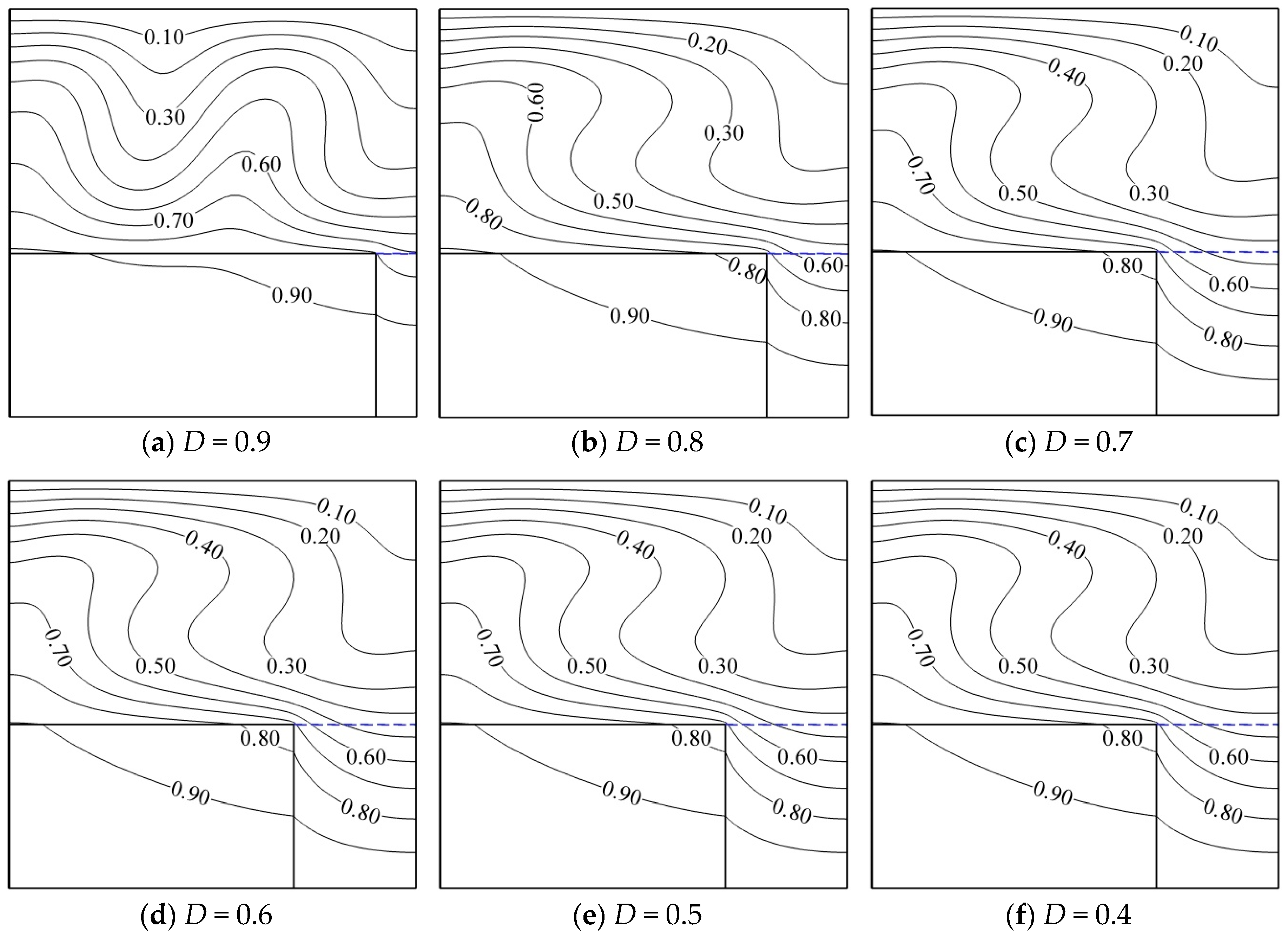
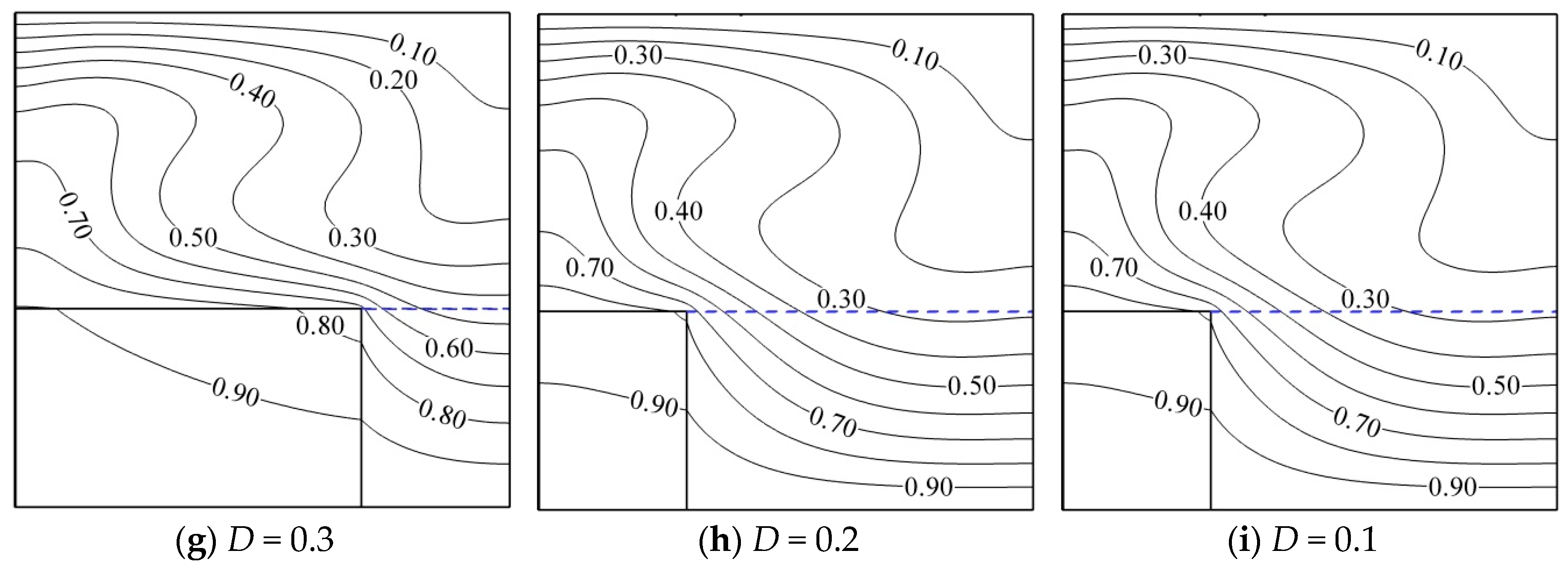
4.4. The Effect of the width (D) of Solid and Porous Media
Figure 15 and
Figure 16 show the effect of changing the width of the solid and porous medium (
D) on the streamline and isotherms. The height of the solid and porous media is constant and only the location of the interface between the two media, which is indicated by the parameter
D, is changed.
Figure 15a shows the isotherms for
D = 0.9. Due to the decrease in the width of the porous medium, the heat transfer occurs mainly from the solid medium to the cavity.
In the nanofluid- filled portion, the isotherms are as such that they indicate the lack of strong circulation of nanofluid. By decreasing the width to D = 0.8, nanofluid obtains more freedom such that the isotherms indicate it. Further, by decreasing the width of the solid medium and the porous medium to D = 0.1, the line θ = 0.9 continues to cut the solid medium. This is due to the high conductivity of the solid medium which is almost at a hot temperature.
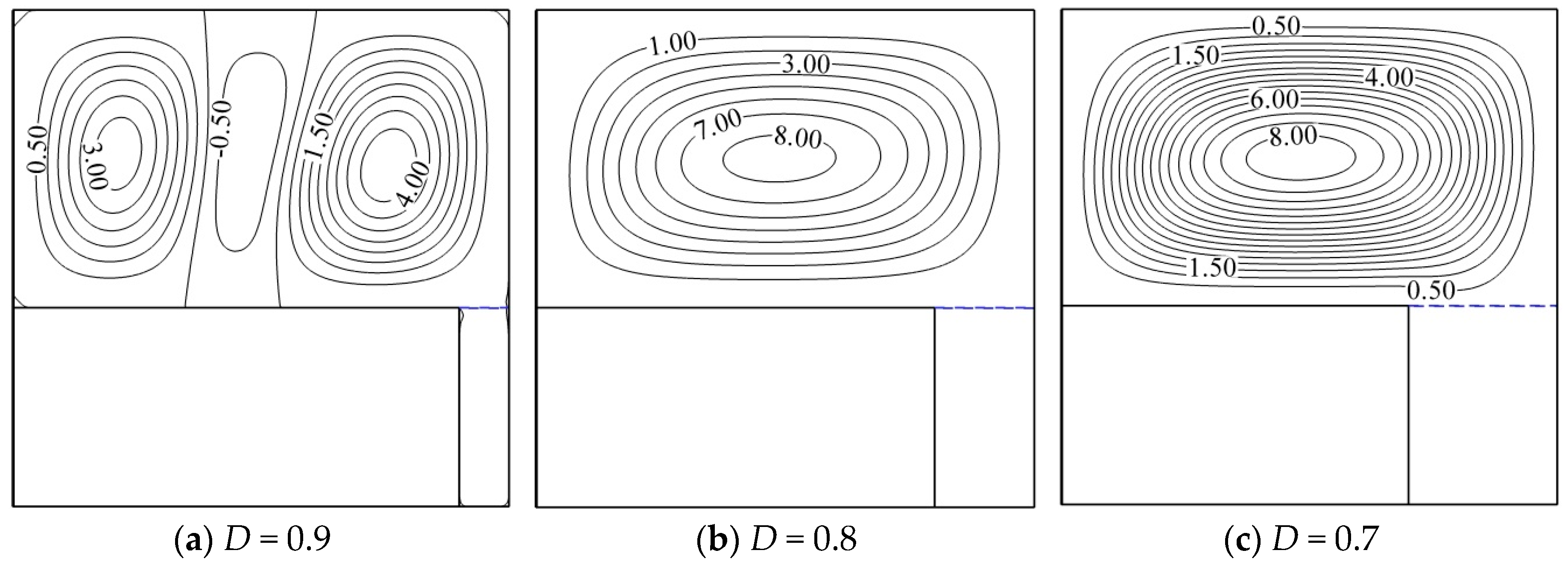
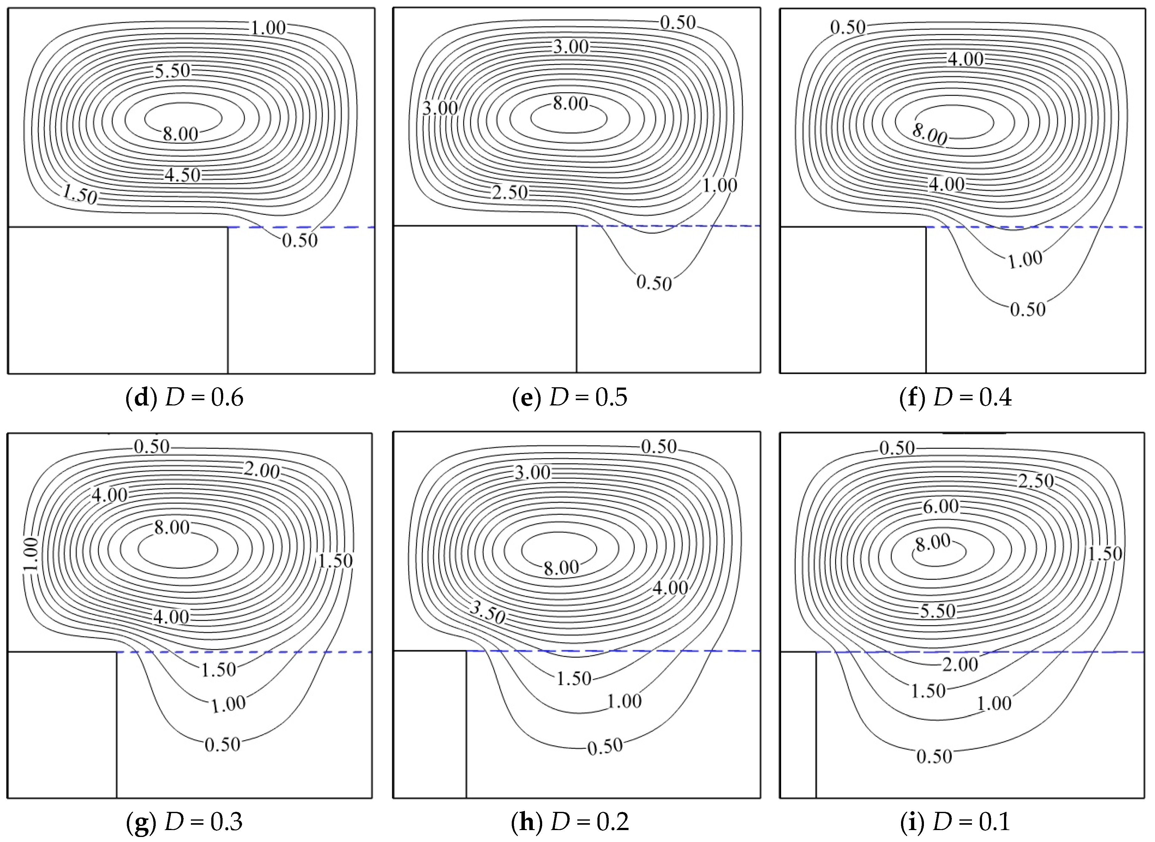
Figure 16 shows the effect of changing the width of the solid and the porous media (
D) on the streamline lines. As shown in
Figure 15, when the width of the solid medium is considered as
D = 0.9, the heat transfer occurs mainly from the solid media, while the mechanism only causes the bottom heating in the nanofluid- filled portion. Although it was already said that a part of the heat transfer occurs from the vicinity of the solid medium due to its presence, it can be seen in
Figure 16a that the heat transfer from the vicinity of the solid medium is practically negligible due to the significant decrease in the width of the porous medium and the occurrence of the bottom heating and the formation of Rayleigh-Benard vortices are evident. By increasing the width of the porous medium, the nanofluid enclosed in the porous matrix obtains more freedom and the fluid circulates freely in the entire cavity by exchanging heat with the solid medium. Thus, in
Figure 16b, we can see the elimination of Rayleigh-Benard vortices and the formation of a general vortex in the cavity. However, in
Figure 16d, the flow in the porous medium is negligible up to
D = 0.6. By increasing the width of the porous medium, the freedom of the fluid and the enhancement of the flow occur in the porous medium so that the enhancement reaches its maximum in
D = 0.1, and the flow lines are significantly enhanced in the porous medium.
4.5. The Effect of the Height (W) of Solid and Porous Media
Figure 17 and
Figure 18 show the streamline and isotherms for different values of the height (
W) of the porous and solid media. It is clear that the given parameter ranges from 0 to 1, and as the number goes up, the height of the solid and porous media increase simultaneously and the nanofluid-filled medium is narrowed. Additionally, by decreasing it, the height of the solid and porous medium decreases simultaneously, leading to an increase in the nanofluid-filled medium. The results from
Figure 17 for the streamline lines indicate that increasing the parameter
W actually leads to splitting the cavity in two.
Figure 17a shows the streamline lines only in the right half of the cavity, which is filled with porous medium, and the space between the solid medium and the cold wall is actually without flow. This definitely affects the heat transfer in the cavity. By reducing the amount of
W and increasing the volume between the solid medium and the cold wall, the path for the nanofluid circulation is opened, and as the parameter
W decreases, the flow lines move toward this region. However, in
Figure 17d where
W = 0/6, we see the formation of Riley-Benard vortices in the distance between the solid medium and the cold wall, because the solid medium is approximately at a hot temperature. In addition, a larger vortex contains the porous medium and a half of the nanofluid medium. On the other hand, the larger vortex circulates in a clockwise direction and the Rayleigh-Benard vortex circulates in a counterclockwise direction according to the sign of the values inserted. The effect of this for the heat transfer in the cavity should be considered. Further, with a greater decrease in the height of two solid and porous media, we continue to see the formation of the central and single vortices. By reaching
W = 0.1, due to the significant decrease in the height of the solid medium, the flow regime acts in such a way that a small counterclockwise vortex is created in the upper corner of the cavity. This vortex is not a Rayleigh-Benard vortex, and only the flow regime created causes its formation.
Figure 18 shows the isotherms for different values of the height (
W) of the porous and solid media. The above figures are equivalent to
Figure 17 and will be compared to them. In
Figure 18a, due to the great height of the solid medium, the heat has not been able to penetrate completely into the solid medium and the temperature lines cut it many times. The above figure shows that the upper boundary of the solid medium is at an average temperature (
θ) of 0.5. This causes the upper boundary to have a low temperature, and due to its low difference with the cold wall temperature (
θ = 0) and the spatial constraints of this region, the lack of fluid circulation in the interface between the solid medium and the cold wall in accordance with
Figure 18a is justifiable. However, the point that is important in
Figure 18a is the great height of the solid medium and its relatively high temperature compared to the circulating nanofluid, causing the formation of the heat transfer from the adjacent side in the half of the cavity. It is important to consider how the heat transfer occurs in the cavity in these conditions. By continuing the decrease in the parameter
W, the solid and porous media becomes smaller, causing an increase in the space for the nanofluid to circulate at the top of the cavity. This has led to a change in the isotherms considering the flow regime in the cavity. Finally, in the case of
W = 0.1, the solid medium is at a completely hot temperature, justifying the failure of the temperature lines to cut the solid medium.
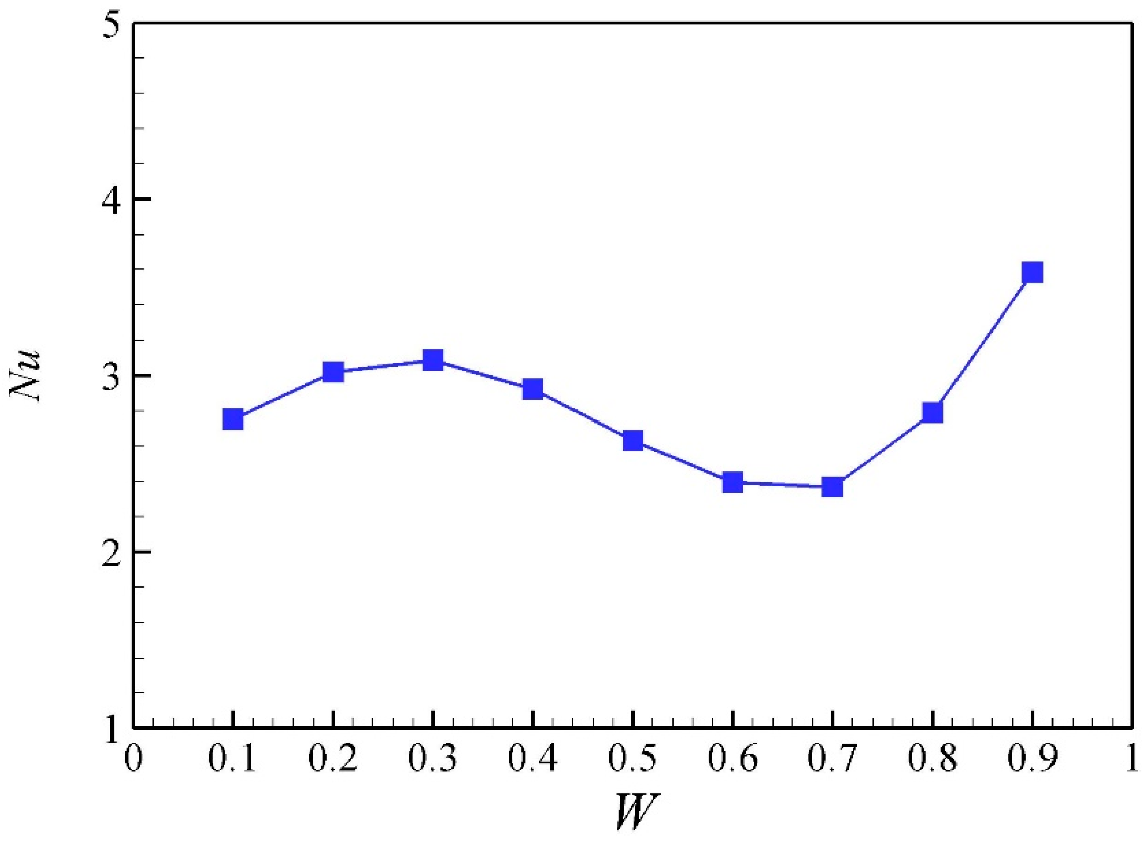
Figure 19 shows the Nusselt number for the different values of the height (
W) of the solid and porous media. As shown in
Figure 17 and
Figure 18 for the streamline and isotherms, changes in this parameter result in major changes in the flow regime in the cavity, where only one vortex is formed in the cavity, or two vortices are formed in the cavity at some values of
W. However, the Rayleigh-Benard vortex is formed on top of the solid medium at
W = 0.6. Now, we examine the effect of each of the above values on the heat transfer.
Figure 19 shows that the maximum Nusselt number occurs in
W = 0.9, where the height of the solid and porous media is such that the nanofluid circulates in half of the cavity. In this amount of
W, heat is transferred mainly to the nanofluid not from the bottom of the cavity, but from the solid wall in the vicinity of the nanofluid. However, the minimum Nusselt number occurs in
W = 0.7. On the other hand, an acceptable Nusselt number is obtained where
W = 0.1. At this amount of
W, the height of the solid and porous media is minimized and the nanofluid-filled medium has a large volume. The reason for this is the increased volume of the nanofluid portion which has greater space in the cavity for the fluid circulation with the decreased height of the solid and porous media (especially the solid medium), making it easy to circulate fluid, increase fluid velocity and consequently increase heat transfer.
5. Conclusions
In the present study, the free convection heat transfer of hybrid nanofluids in a closed cavity was investigated considering the porous and solid media. The cavity was in a square form such that its bottom and top walls were assumed to be insulated in hot and cold temperatures, respectively. The cavity was divided into three portions, including a portion filled with hybrid nanofluids, a porous medium, and a solid medium. In this way, the cavity was analyzed considering the bottom wall heating. The portion filled with hybrid nanofluids contained copper and aluminum oxide hybrid nanoparticles of 20 to 40 nm in size. The governing equations for the nanofluid portion with a homogeneous form were extracted assuming thermal non-equilibrium between the porous and solid media and have been converted to their non-dimensional form. The problem was solved numerically using the finite element method. Subsequently, the important parameters affecting the heat transfer from the cavity were discussed and the effect of each on the heat transfer was measured. The results were presented in figures, tables, curves, and contours, and were discussed in detail. The results indicate that in the hybrid nanofluid portion, the heat transfer can be enhanced by adding nanoparticles to the base fluid, while the viscosity overcomes the thermal conductivity and impairs the heat transfer with an increase in nanoparticles volume concentration. In the porous medium, increasing the ratio of nanofluid conductivity to the porous matrix, Darcy number, and porosity coefficient causes the decreased heat transfer, the increased heat transfer, and the increased heat transfer, respectively. The solid portion is also directly related to the ratio of the solid conductivity to the nanofluid, and its increase leads to enhanced heat transfer. In addition, increasing the Rayleigh number causes increased heat transfer, and the increase in the volume of the nanofluid portion enhances heat transfer due to the enhancement of the nanofluid circulation. Some important conclusions are as follows:
- (1)
Adding nanoparticles to the pure fluid can decrease or increase heat transfer when considering Rayleigh number. The addition of nanoparticles changes two effective parameters: thermal conductivity and second, dynamic viscosity, while both parameters increase by adding nanoparticles. However, in lower Rayleigh numbers, the effect of increased thermal conductivity overcomes the effect of increased dynamic viscosity and the addition of the nanoparticles and the increased volume fraction results in the increased heat transfer in the cavity. In higher Rayleigh numbers, the effect of increased dynamic viscosity overcomes the effect of increased thermal conductivity and the addition of the nanoparticles and the increased volume fraction results in the decreased heat transfer in the cavity.
- (2)
The effect of the Darcy number as a non-dimensional permeability on the heat transfer in the cavity has a direct effect so that with its increase, the heat transfer is increased and with its decrease, the heat transfer is decreased.
- (3)
The porosity coefficient is directly related to the heat transfer and, as it increases or decreases, heat transfer either increases or decreases.
- (4)
The change in the width of the solid and porous media causes a change in the flow regime in the cavity and has an increasing or decreasing effect on the heat transfer.
- (5)
The change in the height of the solid and porous media cause a change in the flow regime in the cavity and has an increasing or decreasing effect on the heat transfer.
- (6)
The relationship between the Rayleigh number and the heat transfer is direct, and its increase or decrease can increase or decrease heat transfer in the cavity.


