Roof Cutting Parameters Design for Gob-Side Entry in Deep Coal Mine: A Case Study
by
Deyuan Fan
1, 
Xuesheng Liu
1,2,*,
Yunliang Tan
1,
Shilin Song
1,
Qingheng Gu
1,
Lei Yan
3 and
Qiang Xu
1 1
State Key Laboratory of Mining Disaster Prevention and Control, Shandong University of Science and Technology, Qingdao 266590, China
2
State Key Laboratory of Coal Resources and Safe Mining, China University of Mining and Technology, Xuzhou 221116, China
3
Suncun Coal Mine, Xinwen Mining Group Co., Ltd., Taian 271233, China
*
Author to whom correspondence should be addressed.
Energies 2019, 12(10), 2032; https://doi.org/10.3390/en12102032
Submission received: 6 May 2019
/
Revised: 22 May 2019
/
Accepted: 25 May 2019
/
Published: 27 May 2019
Abstract
:Roof cutting is an effective technique for controlling the deformation and failure of the surrounding rock in deep gob-side entry. The determination of the roof cutting parameters has become a popular research subject. Initially, two mechanical models are established for the non-roof-cutting and roof-cutting of gob-side entry in deep mining conditions. On this basis, the necessity and significance of roof cutting is revealed by analysing the stress and displacement of roadside prop. The Universal Distinct Element Code numerical simulation model is established to determine the key roof-cutting parameters (cutting angle and cutting height) according to the on-site situation of No. 2415 headentry of the Suncun coal mine, China. The numerical simulation results show that with the cutting angle and height increase, the vertical stress and horizontal displacement of the coal wall first increase and then decrease, as in the case of the vertical stress and displacement of roadside prop. Therefore, the optimum roof cutting parameters are determined as a cutting angle of 70° and cutting height of 8 m. Finally, a field application was performed at the No. 2415 headentry of the Suncun coal mine. In situ investigations show that after 10 m lagged the working face, the stress and displacement of roadside prop are obviously reduced with the hanging roof smoothly cut down, and they are stable at 19 MPa and 145 mm at 32 m behind the working face, respectively. This indicates that the stability of the surrounding rock was effectively controlled. This research demonstrates that the key parameters determined through a numerical simulation satisfactorily meet the production requirements and provide a reference for ensuring safe production in deep mining conditions.
1. Introduction
Gob-side entry retaining (GER) technology has been widely applied in Chinese coal mines. GER technology is a roadway layout method and surrounding rock control technology that retains the original entry along the gob side to serve the next working face [1,2,3,4]. It can make the requirement for a coal pillar redundant, realise continuous mining, alleviate the tension of mining replacement, and eliminate the stress concentration in the coal pillar. It is one of the most important development directions of coal resource mining in China [5,6,7,8,9]. However, the Chinese coal resources has gradually turned into deep coal mining the buried-depth of which has reached over 800 m in recent years. As compared with shallow and medium buried mining conditions, the buried-depth of which being about 100–500 m, the microstructures, basic mechanical characteristics, and engineering responses of coal and rock have changed significantly in response to the “three highs and one disturbance” environment [10,11,12,13]. The main features are that the surrounding rock has a large deformation, high deformation speed, long deformation duration, and rheological characteristics. Hence, maintenance of the gob-side entry becomes extremely difficult, and large deformation and failure accidents occur occasionally [14,15,16,17,18].
Many theoretical studies and field practices on GER technology under deep mining conditions have been completed, and three major advancements should be considered. First, the surrounding rock deformation characteristics and failure evolution law of deep GER are revealed under various geological conditions [19,20,21,22,23]. The roof of the gob-side entry is simplified into a rectangular “superposed stratified plate” structure [24,25], and the concept of the strip segmentation method for the roof load is proposed according to the theory of elastoplastic mechanics. On this basis, Kang et al. [26,27,28] used a numerical analysis method to identify the influence mechanism of the roof fracture location, roof rotation, and long-term creep of the surrounding rock in deep GER and presented the principle of a supporting design. In addition, the characteristics and evolution mechanism of floor heave in gob-side entry were studied. The evolution process can be divided into five stages (slip-bend line formation, shear dislocation failure, shear breakage, extrusion flow, and delamination stages) [29,30,31,32]. Second, the roadway support technology of GER is improved [33,34,35]. The research and development of high-prestressing, high-strength bolt and anchor cable can be used to effectively control roof rock expansion and separation, improve the roof stability, and solve the difficult technical problem for deep gob-side entry support [36,37,38]. Third, the roadside support technology of GER was optimised [39,40,41]. High-water quick-setting materials [42,43,44,45] and paste materials [46,47,48] are widely used because of their high strength and low cost, and they have gradually replaced traditional wooden stacks, intensive individual props, gangue bags, and concrete blocks. Tan et al. [49,50,51,52] proposed a soft–strong combined roadside support structure under the condition of a long, lateral hanging roof, which transfers the weight of the roof-strata to the gangues in goaf through the moderate yielding of the roadside support. This effectively solves the serious problem of large deformations and failures of roadside supports. Many field practices have shown that these methods effectively guarantee the GER safety in thin and medium-thick coal seams under deep mining conditions and have realised remarkable economic and social benefits.
However, in the above research, the control of the surrounding rock deformation was achieved mainly by applying passive support. This will not only cause accidents such as supporting failure and rib spalling in deep mining conditions, but also increase the supporting cost and workload, affect the mining progress and continuity. Therefore, the technique of no-pillar mining with automatically formed GER was proposed [53,54,55,56,57,58]. The roof was presplit along the gob side by borehole blasting, the gob-side roof was cut down, and the goaf was filled owing to the working face advanced, which based on “roof-cutting short cantilever beam” theory. This method reduces the load of overlying strata, and exerts the bearing capacity of gangues. Stress on roadside props was effectively reduced, and the surrounding rock stability of gob-side entry is maintained. Moreover, the use of this method realises a combination of mining and excavation, simplifies the mining process, and achieves good results in field applications.
To further expand the application range of roof cutting technology in deep coal mines, this study was focused on the construction of the corresponding structural mechanical models of gob-side entry and revealed the necessity of roof cutting through mechanical analysis, which is based on the deep mining conditions of Suncun coal mine. We then used UDEC software to research the stress and displacement variations of coal wall and roadside prop for different roof cutting parameters, and the optimal key parameters, cutting angle and height were determined. Finally, a field application was performed at the No. 2415 headentry of the Suncun coal mine.
2. Engineering Overviews
2.1. Geological and Mining Conditions
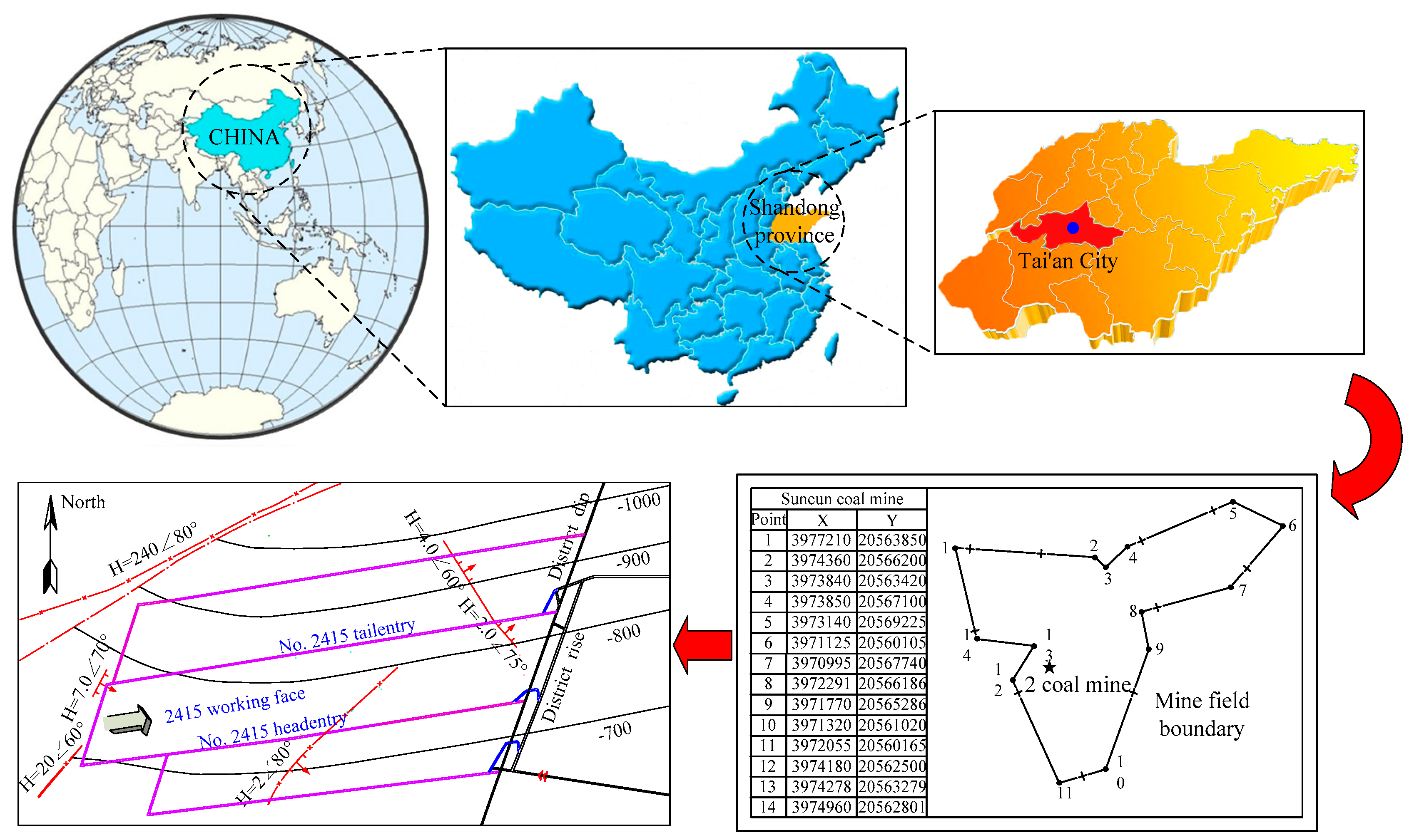
Suncun coal mine is in Tai’an, Shandong province, China. The mine field is 9.1 km long, 3 km wide, and covers an area of 21.2 km2. The southern boundary of the minefield is a coal-seam outcrop. The northern boundary is a coal seam with a contour of −1050 m. The western boundary is the original position of fault F8. The eastern boundary is the boundary of the northern Jurassic scouring boundary between faults F6 and F10. The coal mine contains 19 coal seams, where No. 2, No. 4, and No. 11 are the main seams. The geological coal reserves are 96,634,900 t and the recoverable reserves are 49,958,400 t, of which the recoverable reserves below the −800 m level account for 64%, which has a very good development prospect. The layout of the mine location and 2415 working face are shown in Figure 1.
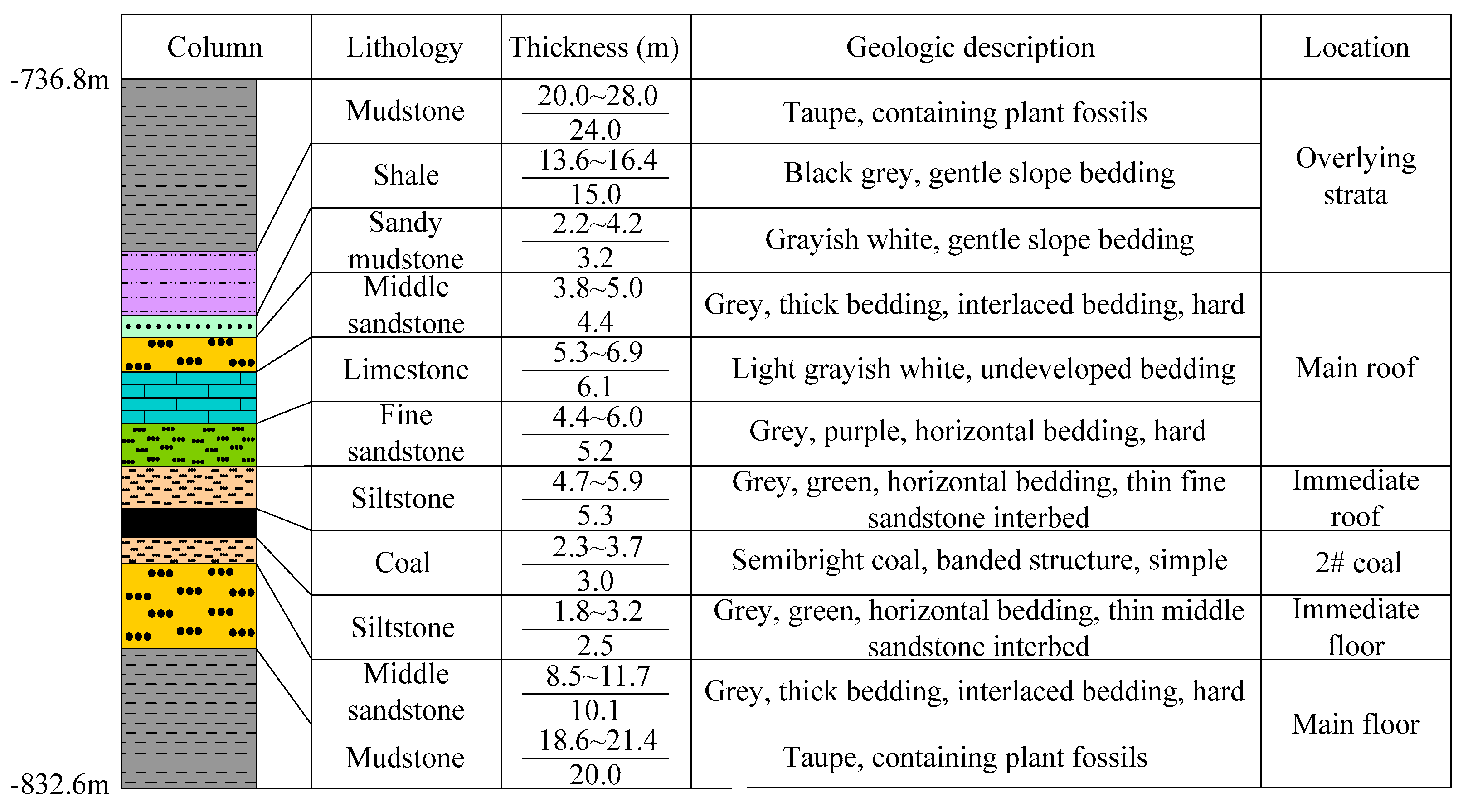
The 2415 working face is located at level −800 m, 2# coal seam, 2nd mining area. The strike length is 336–349.5 m, with an average of 342.6 m. The inclined length is 207.7–209.2 m, of which the average is 208.5 m. Furthermore, the horizontal area of the working face is 69,159.5 m2, and the inclined area is 71,432.1 m2. Its elevation is −760.83 to −810.93 m, and the buried depth is 730.93–832.93 m. Moreover, the thickness of the coal seam is 2.3–3.7 m, with an average of 3.0 m. The dip angle of the coal seam is 13°–16°, with an average of 14.5°. The histogram of the 2# coal seam and its roof-and-floor rock strata are shown in Figure 2.
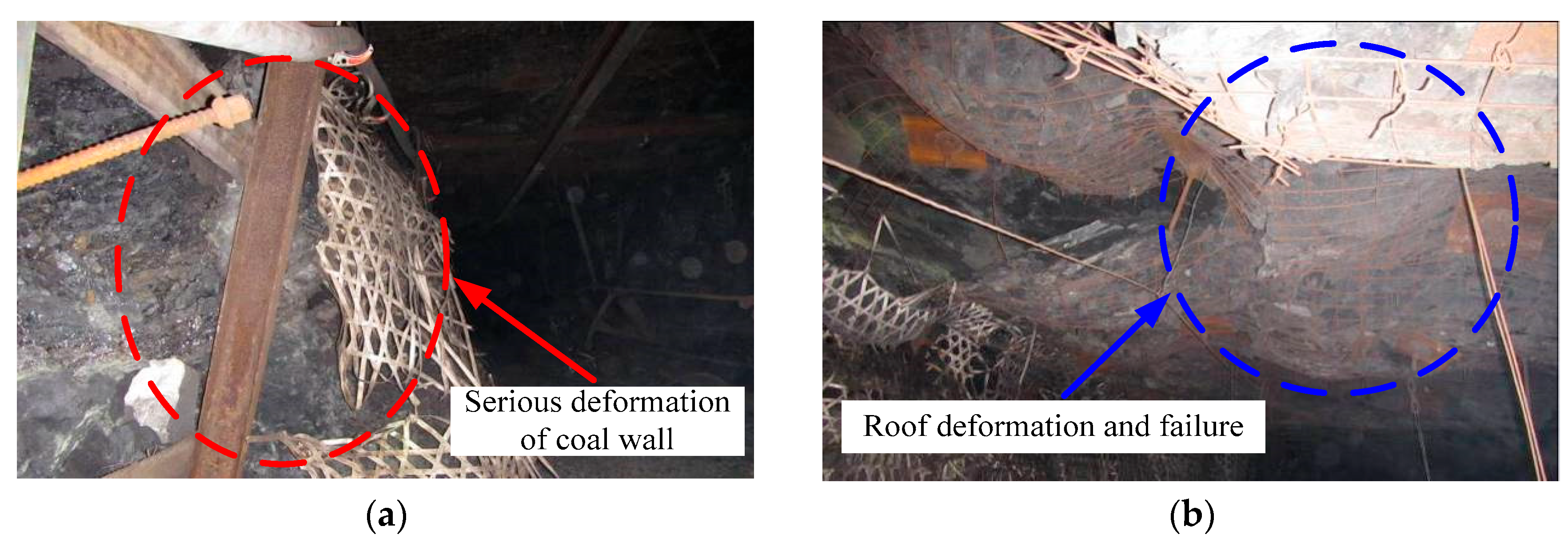
The No. 2415 headentry is a gob-side entry, and the roadway section is rectangular with a width of 4.0 m × height of 3.0 m. Owing to hard roof condition and some complex environmental factors (e.g., three highs and one disturbance) in deep mines, the roof of the No. 2415 headentry was seriously deformed, and the surrounding rock was extensively damaged, as shown in Figure 3.
2.2. Rock Mass Properties
Rock mechanical properties has an important influence on the roadway stability. To provide the guidance and reference for the numerical simulation, the mechanical properties of the surrounding rock at 2415 working face in Suncun coal mine were obtained by uniaxial compression test on in-site rock specimens.
The rock specimen properties were obtained through laboratory compression tests on small rock specimens as suggested by the International Society for Rock Mechanics [59]. As shown in Figure 4, the loading system comprises a Shimadzu AG-X250 electronic universal testing machine. The testing machine is driven by an AC motor servo, and the loading mode has a double screw structure. This equipment has good stability and high precision; it can be used to perform conventional mechanical tests such as compression and tension. The maximum test load can reach 250 kN. The displacement loading control was used during the test until the sample was destroyed, and the loading rate was set as 0.0005 mm/s.
However, the discontinuity of the engineering rock mass resulted in a reduced macro-strength; hence, the rock mass strength was much smaller than that of specimens. We modify the mechanical properties of the rock mass appropriately to fit the numerical simulation. The mechanical properties used for the simulation are listed in Table 1.
3. Necessity of Roof Cutting Study
3.1. Mechanical Model
When GER technology is applied under a condition of deep hard roof mining, the lateral immediate roof collapses into the goaf, and the length of the hanging roof gradually increases. Furthermore, the main roof rotary subsides along the fracture line as the working face advanced [19,20,21,22,23]. Under these conditions, it becomes very difficult for the traditional roadway support to resist the large pressures caused by the surrounding rock deformation and lateral roof subsidence, which is destructive to the roadside supports and stability of the roadway. The roof cutting can cut off the hanging roof effectively and make the collapsed gangues act as a bearing body, which can fully exert its bearing characteristics to support the upper rock strata. In this manner, the stress of the roadside support body can be reduced, and the stress environment of the surrounding rock can be improved. To clarify the necessity and significance of roof cutting, simplified mechanical models are established for non-roof-cutting and roof-cutting conditions of GER, as shown in Figure 5.
The roadway roof is approximately regarded as an elastic beam supported by coal wall at one end, roadside prop in the middle, and gangues in goaf at the other end. In Figure 5, the mining height is h; the immediate roof thickness is mZ; the main roof thickness is mE; the distance from the fracturing line to the coal wall is L0; the width of the roadway is LR; the length of the hanging roof is LS; the overlying strata load, q, is uniformly applied on the main roof; and the length of the rock beam B, is LE. The coal wall supporting resistance can be expressed by FM1 and FM2, respectively, and the supporting resistance of roadside prop are P1 and P2 respectively. The supporting effect of gangues can be expressed by a trapezoidal distributed load, ranging 0_q3, and the bearing length is LG1 and LG2 respectively.
3.2. Mechanical Analysis
3.2.1. Roadside Prop Displacement
As shown in Figure 5a, in the process of rock beam B subsidence, the ultimate subsidence for non-roof-cutting is determined as per the theory of elasticity [2,7].
where KA is the coefficient of dilatancy of the roof rock, which is related to the nature of the collapsed gangues. It generally ranges from 1.15–1.35.
According to the movement feature of the overlying strata, the roadside prop displacement of non-roof-cutting SC1 can be obtained using the following equation.
where A = L0 + LR + LS.
As shown in Figure 5b, the ultimate subsidence for roof-cutting is determined as follows.
At this time, the displacement of the roadside prop for roof-cutting SC2 can be obtained as follows.
where B = L0 + LR.
On using Equations (2)–(4), the following can be obtained:
Therefore, from Equation (5), it can be observed that
In addition, according to the roof movement law in the mining process, the lateral main roof rotation angle of non-roof-cutting is as follows.
Similarly, the lateral main roof rotation angle of roof cutting can be obtained.
Through the analysis of the above equations, the following can be derived.
From Equation (9), it can be observed that the lateral main roof rotation angle and the roadside prop displacement of the roof-cutting condition are smaller than those of the non-roof-cutting condition. Therefore, roof cutting can be effectively used to reduce the displacement of roadside prop, limit the rotary subsidence of the main roof, which benefit the gob-side entry stability.
3.2.2. Roadside Prop Stress
While adopting roof cutting, as shown in Figure 5b, the weight of immediate roof FZ2 is
where γZ is the volumetric weight of immediate roof. γE is the volumetric weight of main roof.
The weight of main roof FE can be determined as follows.
Assuming that the bearing force of the gangues on the roof has a linear distribution, according to the rock dilatancy [52,53,54,55], the supporting resistance of the gangues in goaf for non-roof-cutting FG1 is as follows.
where LG1 is the gangues bearing length m on main roof for the non-roof-cutting condition.
With the lateral main roof subsidence, the contact point between the rock beam B edge and gangue in goaf moves to the left after the roof cutting. At this time, the bearing length of the gangue is LG2:
Therefore, the supporting resistance of gangues FG2 for roof-cutting condition is as follows:
Assuming the roof load is uniformly applied to the roadside prop, and without considering the supporting resistance in the roadway, the mechanical equilibrium equation is established for non-roof-cutting in Figure 5a.
where P1 is the support resistance of the roadside prop for the non-roof-cutting condition, kN.
From Equation (16), we can obtain the following:
Based on the above hypothesis, the mechanical equilibrium equation is established for roof-cutting as shown in Figure 5b.
where P2 is the support resistance of the roadside prop for the roof-cutting condition, kN.
According to Equation (18), the following can be obtained:
Using Equations (2)–(4), the following can be obtained:
Therefore, from Equation (20), it can be observed that
The above analysis shows that after adopting roof-cutting, the roof is cut down and filled with the goaf. The bearing capacity of the gangues is improved, and they act as an active support to the upper strata weight. This reduces the pressure generated by the lateral roof subsidence and its sinking movement space, and fully exerts the bearing characteristics of gangues in goaf, which can greatly reduce the stress on the roadside prop and improve the surrounding rock stability and integration.
4. Determination of Key Roof Cutting Parameters
4.1. UDEC Model Criterion
Discontinuity will cause great defects to rock continuum mechanics. The discrete element method can be used to reflect the failure and mechanical features of surrounding rock in deep mining conditions. Additionally, the failure process can be better revealed by simulating the cracks and joints [60].
As the tensile strength of rock is much smaller than its compressive strength, the Mohr–Coulomb elastoplastic constitutive model is used to realise the tension failure of a block [60]. The failure criterion (, ) as illustrated in Figure 6.
The failure process can be defined from points A to B by Mohr–Coulomb yield function.
where is the friction angle, c is the cohesion, and . From points B to C, a tension yield function is expressed as follows.
where is the tensile strength.
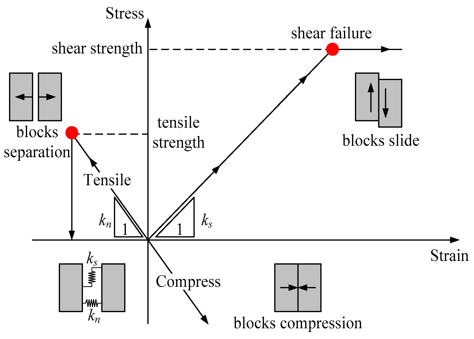
In the contact model, the sliding or opening of the contact surface is realised by using Coulomb friction law, which is very appropriate to simulating the failure process. The contact behavior is simulated by spring slider, and the contact force can be divided into normal stress and shear stress. The contact constitutive behaviour is illustrated as Figure 7.
Depending on the stress state and the characteristics of the contact surface, damage can only occur along the contact by shearing or tension. In the vertical direction, the stress-displacement relationship is considered to be linear and controlled by stiffness kn, which is [60]
where is the increment of effective normal stress; and is normal displacement increment.
The shear stress is controlled by a constant shear stiffness in the shear direction, which is determined by contact characteristics, cohesion (c) and friction angle (). Therefore, if
Then
Or else, if
Then
where is the elastic component in the shear displacement increment and is the total shear displacement increment.
4.2. Numerical Model Establishment and Modelling Procedures
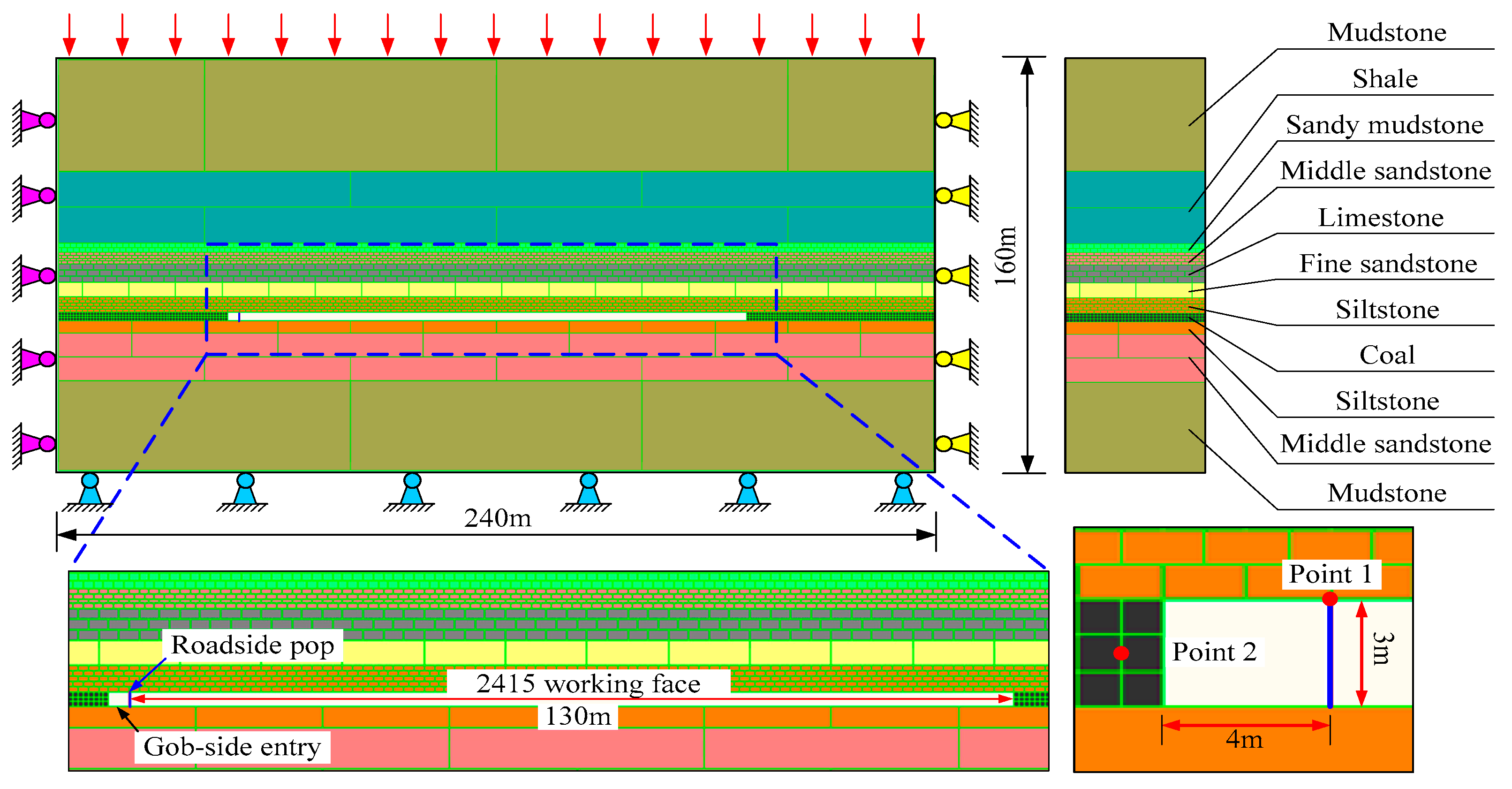
A model was created by UDEC to simulate two key parameters of roof cutting (angles and heights) in the No. 2415 headentry. The simulation model is shown in Figure 8, which is based on the in-site lithological conditions illustrated in Figure 2 and Table 1. The numerical model was 240 m wide and 160 m high and contained 8045 blocks. The gob-side entry of 4.0 m width by 3.0 m height, and the 2415 working face with a 130 m length were simulated by excavating two rectangular openings in the middle respectively.
In the upper boundary, vertical stress was applied to simulate the overlying strata stress. In the two lateral boundaries, horizontal displacement were constrained. In the bottom boundary, the vertical and horizontal displacements were fixed. Before the excavation of roadway and working face, the model was equilibrium to produce the geostress. During the simulation, the “support” element was applied to simulate the roadside prop.
In addition, Monitoring Point 1 is set inside the coal wall to monitor the vertical stress and horizontal displacement of the coal wall. Monitoring Point 2 is arranged on the roadside prop to monitor the vertical stress and displacement after working face excavation.
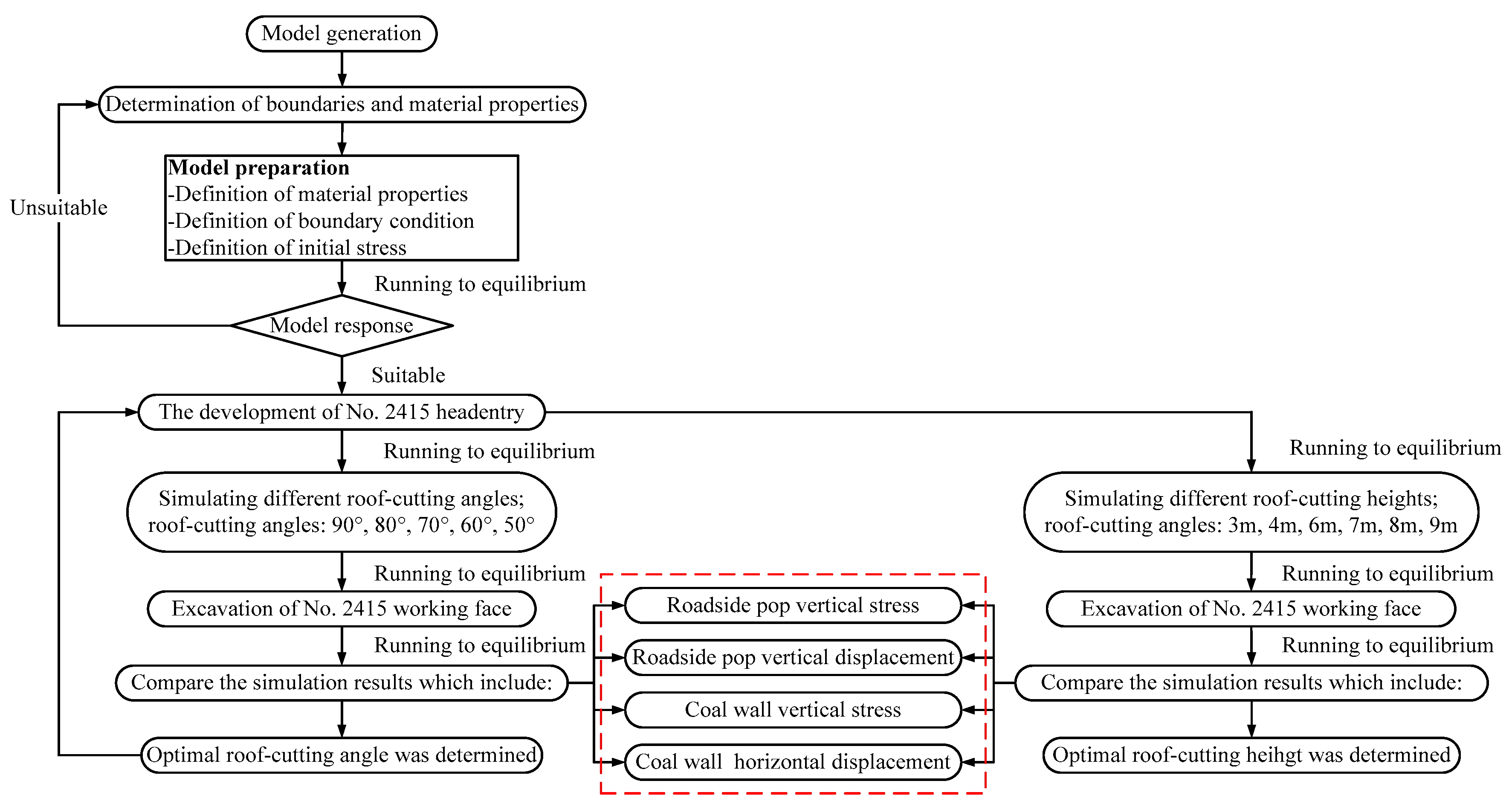
The detailed simulation process was as follows (Figure 9): (1) block and contact model generation, (2) development of the No. 2415 headentry; (3) fixed cutting height to simulate different cutting angles (90°, 80°, 70°, 60°, and 50°); (4) excavation of 2415 working face and determination of the optimal cutting angle; (5) using the optimal cutting angle to simulate various cutting heights (3, 4, 6, 7, 8, and 9 m); (6) excavation of 2415 working face and determination of the optimal cutting height.
4.3. Determination of Key Parameters
4.3.1. Cutting Angle
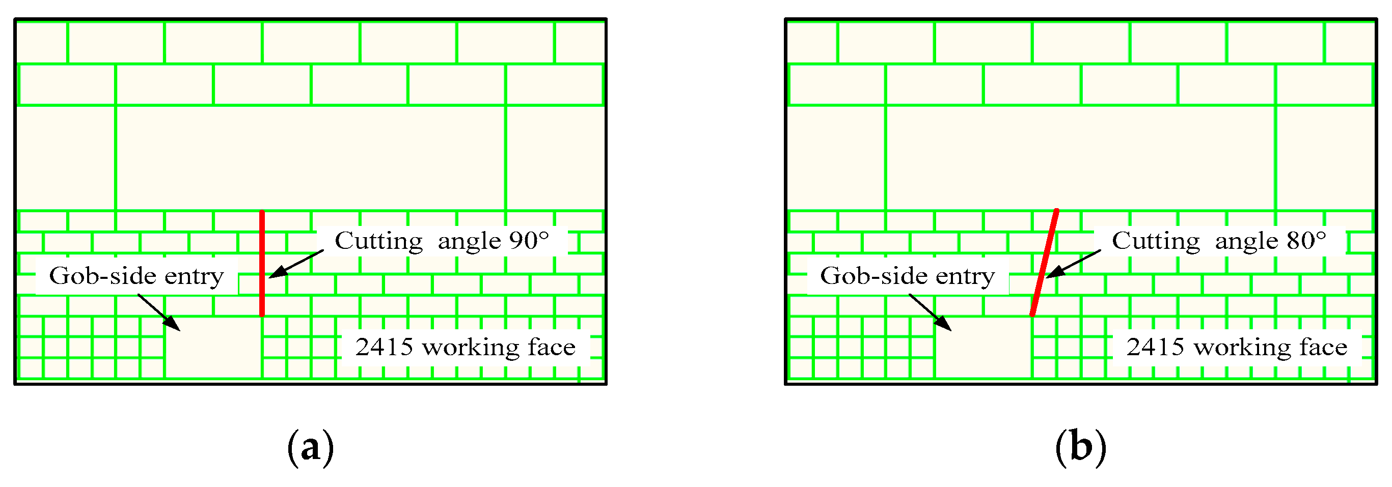
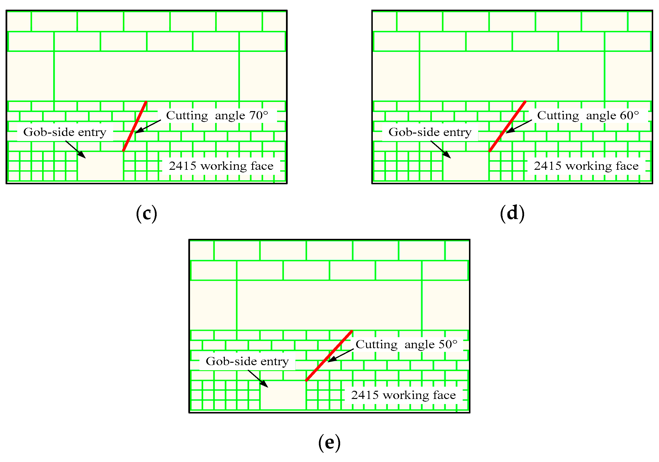
We define the cutting angle as the angle between the cutting borehole and the horizontal line. After adopting the directional roof-cutting boreholes, the boreholes are mutually conductive to form the weak surface structure. After the mining, the roof breaks along the weak surface and collapses to the goaf under self-weight and the overlying strata load. In the numerical simulation, the cutting angles are selected as 90°, 80°, 70°, 60°, and 50°, the cutting height is designed as 5 m, as shown in Figure 10.
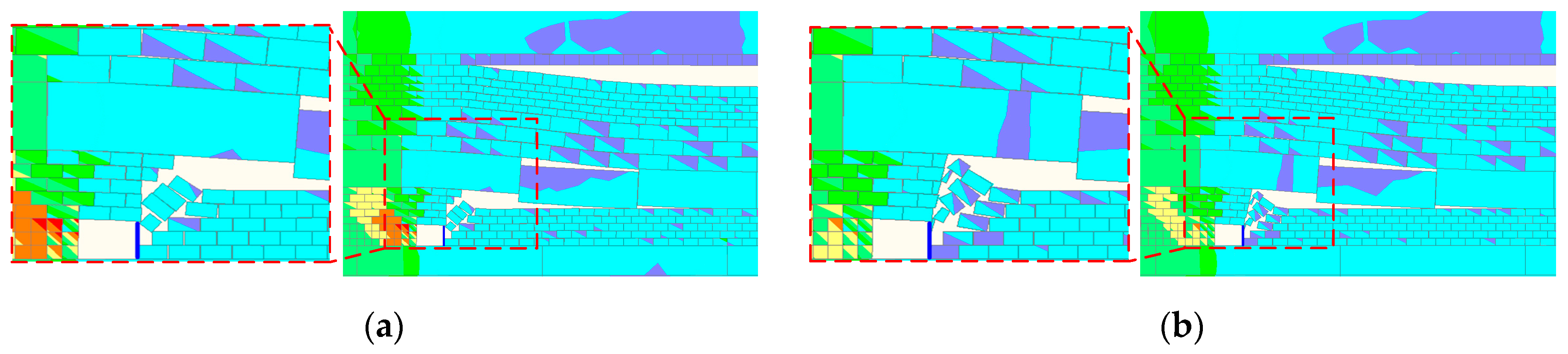
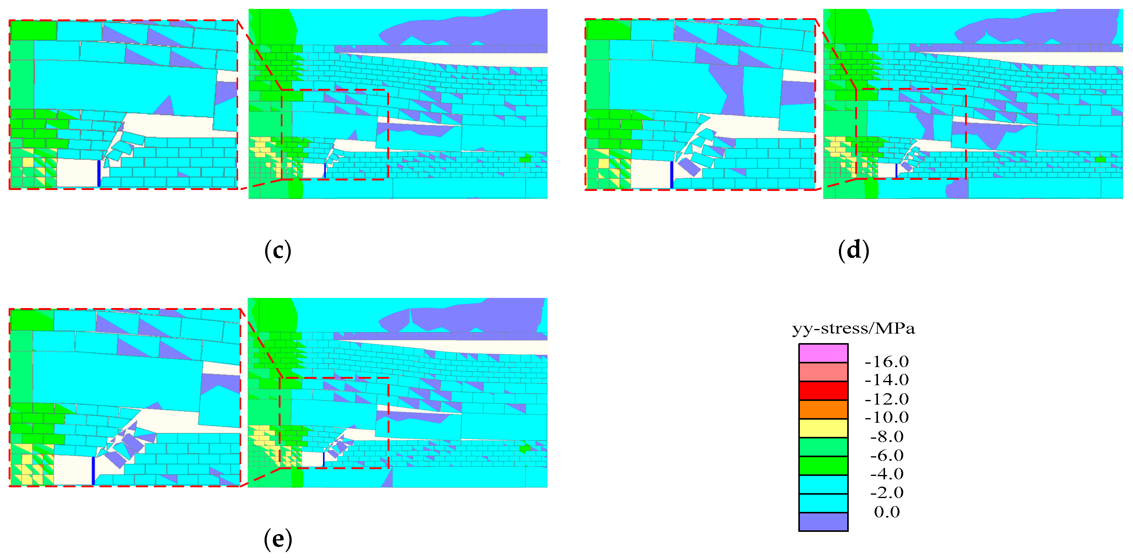
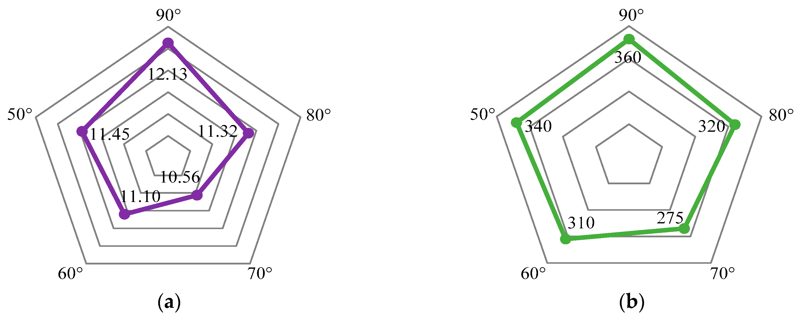
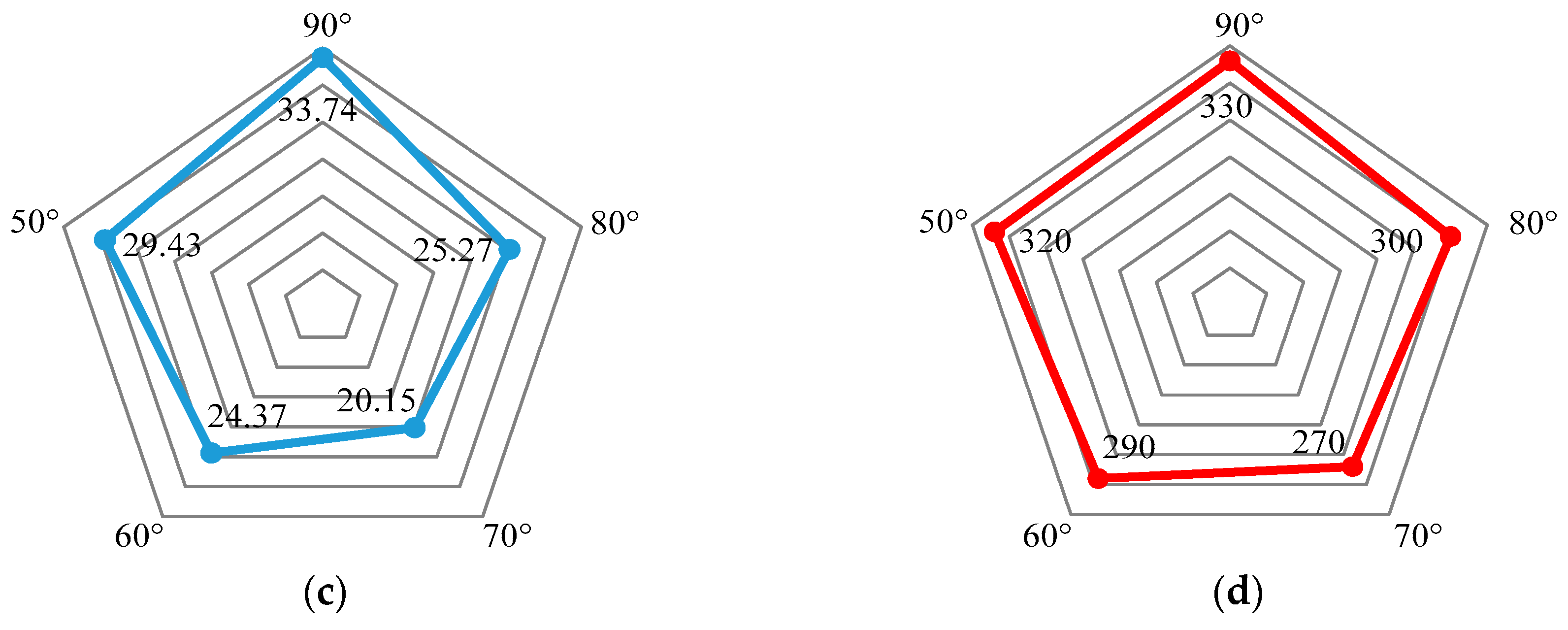
The vertical stress contours and monitoring points curves of the numerical simulation are shown in Figure 11 and Figure 12. With the change of cutting angle, the stress and displacement of coal wall and roadside prop also change in varying degrees. When the cutting angle is 90° (Figure 11a), there is an obvious stress concentration area at the left side of the coal wall after excavation, which is large in scope and near the coal wall surface. Moreover, the roadside prop are subjected to a large compressive stress. The vertical stress peak value at the coal wall is 12.13 MPa, and the horizontal displacement is 360 mm. Meanwhile, the vertical stress peak value at the roadside prop is 33.74 MPa, and the vertical displacement is 330 mm. At this time, the lateral roof of the gob-side entry is only cut down by approximately half, and the roof-cutting performance is poor. When the cutting angle changes from 90° to 80° (Figure 11b), the range of the stress concentration area and stress peak value of the coal wall decrease gradually, and the stress peak value of the roadside prop also exhibits a downward trend. As compared with the cutting angle 90°, the vertical stress peak values at the coal wall and roadside prop decreased by 6.7% and 25.1%, respectively. In terms of displacement, the coal wall horizontal displacement and roadside prop vertical displacement decreased by 11.1% and 9.1%, respectively. At this time, it is more suitable to cut the lateral roof along the gob-side entry; however, the hard roof still cannot be completely cut down. When the cutting angle changes from 80° to 70° (Figure 11c), the vertical stress peak values at the coal side and roadside prop further decreases. As compared with the cutting angle of 80°, the stress peak values at the coal wall and roadside prop decreased by 6.7% and 20.3%, respectively. In terms of displacement, the coal wall horizontal displacement and the roadside prop vertical displacement decreased by 14.1% and 10.0%, respectively. At this time, the lateral roof of the gob-side entry is completely cut off, the coal side and roadside prop displacement is small, and the vertical stress peak value is effectively reduced.
However, the vertical stress peak values at the coal wall and roadside prop exhibit an upward trend with a further reduction in the cutting angle. When the cutting angle changes from 70° to 60° (Figure 11d), the stress peak values at coal wall and roadside prop also increase gradually. As compared with the cutting angle of 70°, the vertical stress peak values increase by 5.1% and 20.9%, respectively. In addition, the displacement also increased in varying degrees. The coal wall horizontal displacement and the roadside prop vertical displacement increased by 12.7% and 7.4%, respectively. At this time, the roof can be completely cut off, but the length of the hanging roof also increases, which lead to the stress and displacement increased in the coal wall and roadside prop. When the cutting angle is changed from 60° to 50° (Figure 11e), the stress peak values at the coal wall and roadside prop continued to rise and showed an increase of 3.2% and 20.7%, respectively, as compared with those at the cutting angle of 60°. Furthermore, the coal wall horizontal displacement and the roadside prop vertical displacement increased by 9.7% and 10.3%, respectively.
As shown in Figure 13, the results can be obtained according to the numerical calculation results above.
- When the cutting angle is 90°, i.e., in the case of vertical roof cutting, the immediate roof is bent and deformed under self-weight and the overlying strata load. Moreover, extrusion friction occurs at the cutting line, which means that the roof is required to overcome the larger rock shear force in order to collapse, and hence, the immediate roof cannot be completely cut off. Therefore, the stress transmission between the roof in the goaf and roadway is still maintained, which results in a large stress and deformation in the gob-side entry. In addition, the roadside prop is subjected to a large compressive stress, which causes severe deformation and damage.
- With the reduction in the cutting angle, the peak stress and displacement at the coal wall and roadside prop decrease correspondingly when the cutting angle is 80°. This indicates that the immediate roof will be more easily cut off when the cutting roof deflects to the goaf at a certain angle. However, the roof in the goaf still experiences some extrusion friction on the roadway roof during the process of collapsing, which results in insufficient cutting.
- With a further reduction in the cutting angle, the stress and displacement at the coal wall and roadside prop are minimised when the cutting angle reaches 70°. This indicates that the extrusion friction at the roof cutting surface can be effectively eliminated, and the stress transmission between the roof in the goaf and roadway is thoroughly cut off, which is beneficial to surrounding rock stability and protecting the roadside prop.
- However, as the cutting angle continues to decrease, the stress and displacement at the coal wall and roadside prop increase to varying degrees when the cutting angle is 60° and 50°. This is because, as the cutting angle decreases, the extrusion friction at the cutting surface will not have a direct impact on the roof cutting effect, but at this time, the length of the hanging roof increases, which increases the roof load as well as the compressive stress on the roadside prop. Therefore, effective pressure relief cannot be achieved.
- Based on the comprehensive numerical calculation results, the optimum cutting angle is 70° for the mining conditions of 2415 working face.
4.3.2. Cutting Height
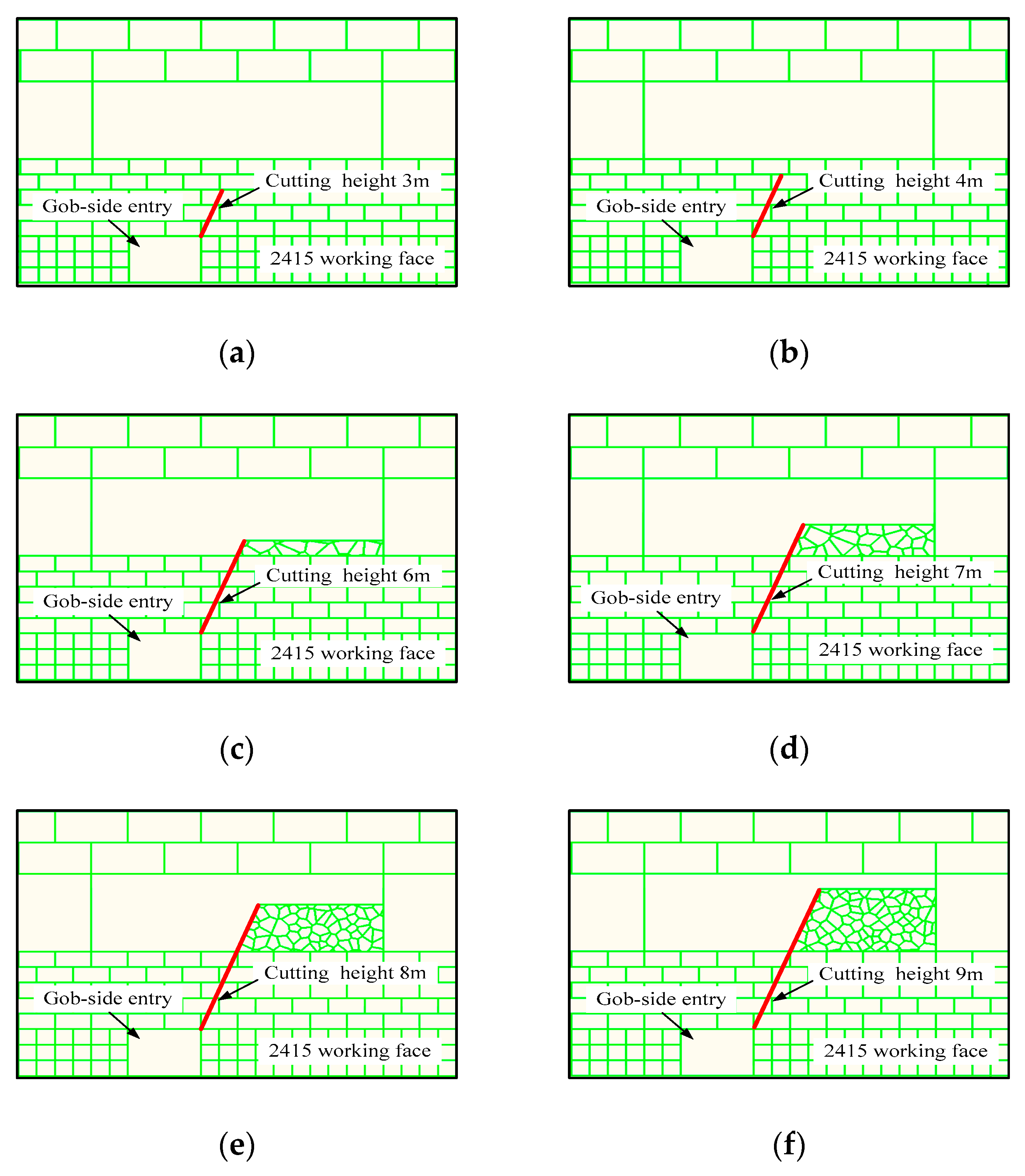
We define the cutting height as the maximum vertical height of the roof cutting borehole. According to the theoretical analysis [55,56,57,58], the cutting height has great impact on the cutting effect. In the numerical simulation, various cutting heights of 3, 4, 6, 7, 8, and 9 m are adopted. The cutting angle is designed as 70° in order to determine the optimum cutting height, as shown in Figure 14.
To simulate the fracture zone in the main roof strata, we use Voronoi tessellation in UDEC to provide randomly sized polygonal blocks. The fracture zone of the main roof is represented by a combination of triangular blocks and interval contact. By dividing each block into a triangular finite difference region, it will not fail due to its elasticity. According to the stress state and the characteristics of the contact surface, the failure only occurs along the contact surface in shear or tension.
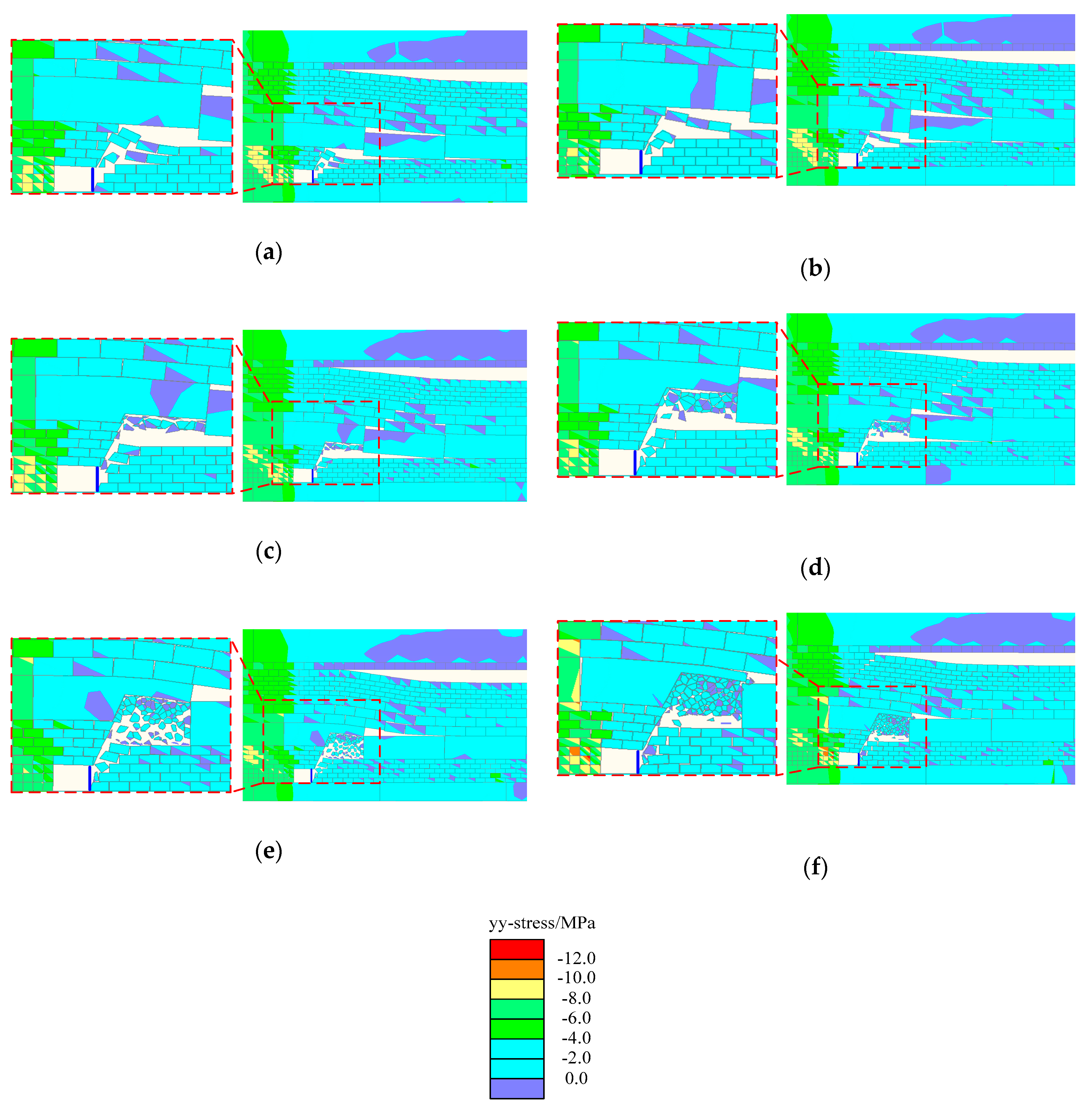
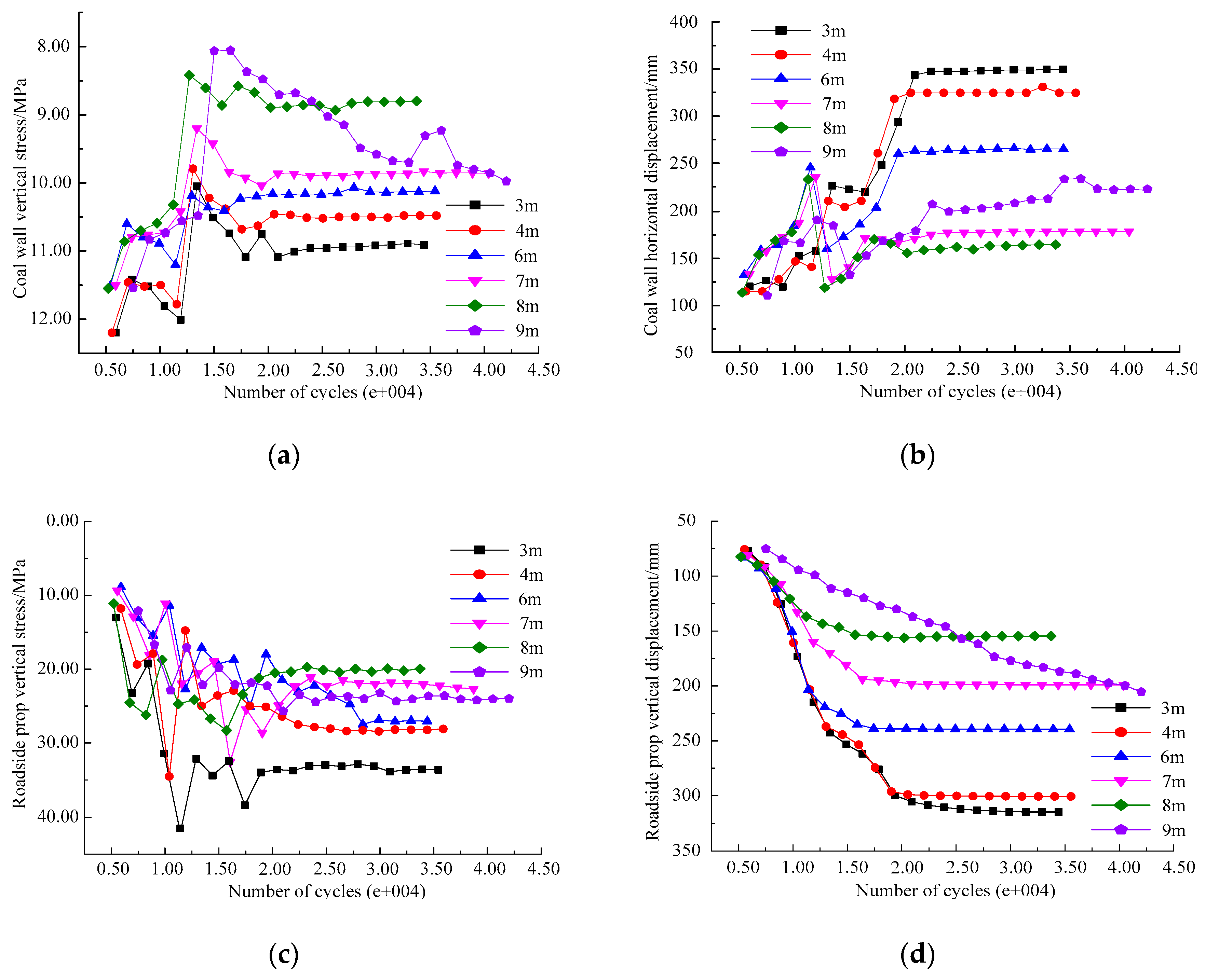
The numerical simulation of the vertical stress contours and the monitoring points curves are shown in Figure 15 and Figure 16. On comparing the various cutting height schemes, the following can be observed.
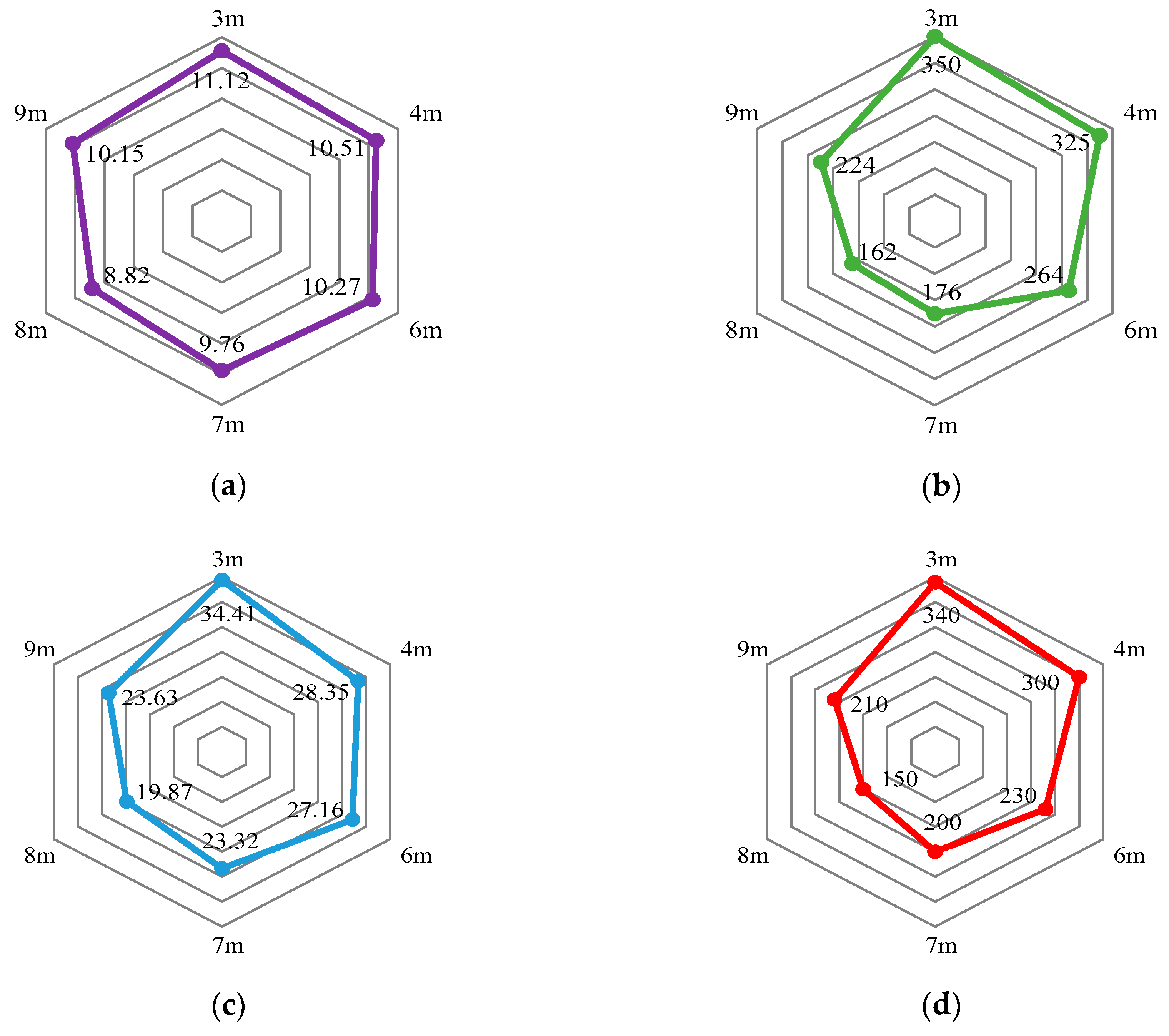
When the cutting height is 3 m (Figure 15a), the vertical stress peak values at the coal wall and roadside prop are 11.12 and 34.41 MPa, respectively, and the coal wall horizontal displacement and roadside prop vertical displacement are 350 and 340 mm, respectively. At this time, the lateral roof of the gob-side entry cannot be completely cut off because of the small cutting height, which is unsatisfactory. When the cutting height increases to 4 m (Figure 15b), the vertical stress peak values at the coal wall and roadside prop decrease by 5.8% and 17.6%, respectively. In terms of displacement, the coal wall horizontal displacement and roadside prop vertical displacement decrease by 7.1% and 13.3%, respectively. At this time, it is easier to cut off the hanging roof, but the stress transmission between the roof in goaf and roadway is still maintained. In addition, the collapsed gangue cannot fill the goaf to support the overlying strata. Therefore, the cutting height should continue to increase to the main roof strata.
When the cutting height is 6 m (Figure 15c), the vertical stress peak values at the coal wall and roadside prop continue to decrease—2.3% and 4.2% lower than those at 4 m—and the displacements decrease by 18.8% and 23.3%, respectively. When the cutting height is 7 m (Figure 15d), the vertical stress peak values decrease by 5.0% and 14.1%, respectively, and the displacement decreases by 33.3% and 13.0%, respectively. When the cutting height is 8 m (Figure 15e), vertical stress peak values of the coal wall and roadside prop are 8.82 and 19.87 MPa, respectively, and the coal wall horizontal displacement and roadside prop vertical displacement are 162 and 150 m, respectively. At this time, the stress peak values at the coal wall and roadside prop reach a minimum, the stress concentration area is smallest far away from the roadway. Moreover, the displacement of coal wall and roadside prop are small, which indicates that the roof cutting has achieved good results at this cutting height.
However, the stress peak values at the coal wall and roadside prop exhibit an upward trend with a further increase in the cutting height. When the cutting height increases to 9 m (Figure 15f), the stress peak value at the coal wall and roadside prop increase gradually by 15.1% and 18.9%, respectively, as compared with those at 8 m. The displacement also increases in varying degrees. The coal wall horizontal displacement and roadside prop vertical displacement increase by 38.3% and 40.0%, respectively.
As shown in Figure 17, according an analysis of the above numerical calculation results, the following can be determined.
- When the cutting height is 3 and 4 m, the hanging roof cannot be completely cut off because of the insufficient cutting height. In addition, the collapsed gangues cannot fill the goaf, which cannot exert the bearing capacity to restrict the main roof movement. Therefore, the stress concentration area of coal wall is large, and the stress peak value is high. Moreover, the roadside prop is subjected to a large compressive stress and suffers obvious deformation.
- When the cutting height is greater than the immediate roof thickness, which means that part of main roof is cut off, the stress peak values and displacement of the coal wall and roadside prop are reduced correspondingly. This is because the immediate roof is cut off, which fundamentally eliminates the inside stress transmission. In addition, the gangues cut from the main roof can be further filled with the goaf according to the rock dilatancy, such that it can limit the movement of the overlying strata, which is beneficial for the stability to roadway surrounding rock. When cutting height is 8 m, the stress peak values and displacement of coal wall and roadside prop roadway are minimised, which effectively controls the deformation and failure at the gob-side entry and greatly reduces the stress on the roadside prop. Roof cutting achieved in this case exhibits the best results.
- However, for a larger cutting height the obtained roof-cutting result is not better. When the cutting height is increased to 9 m, the stress and displacement at the coal wall and roadside prop tend to increase. This is because the cutting height is sufficiently large to destroy the structure of the main roof rock beam, which loses its bearing capacity with respect to the overlying strata. Meanwhile, the upper part of the main roof is compressed and greatly deformed during the process of rotary subsidence, which is not conducive to effective roof cutting.
- Based on the comprehensive numerical calculation results, the optimum cutting height is 8 m for the mining conditions of 2415 working face.
5. Field Application
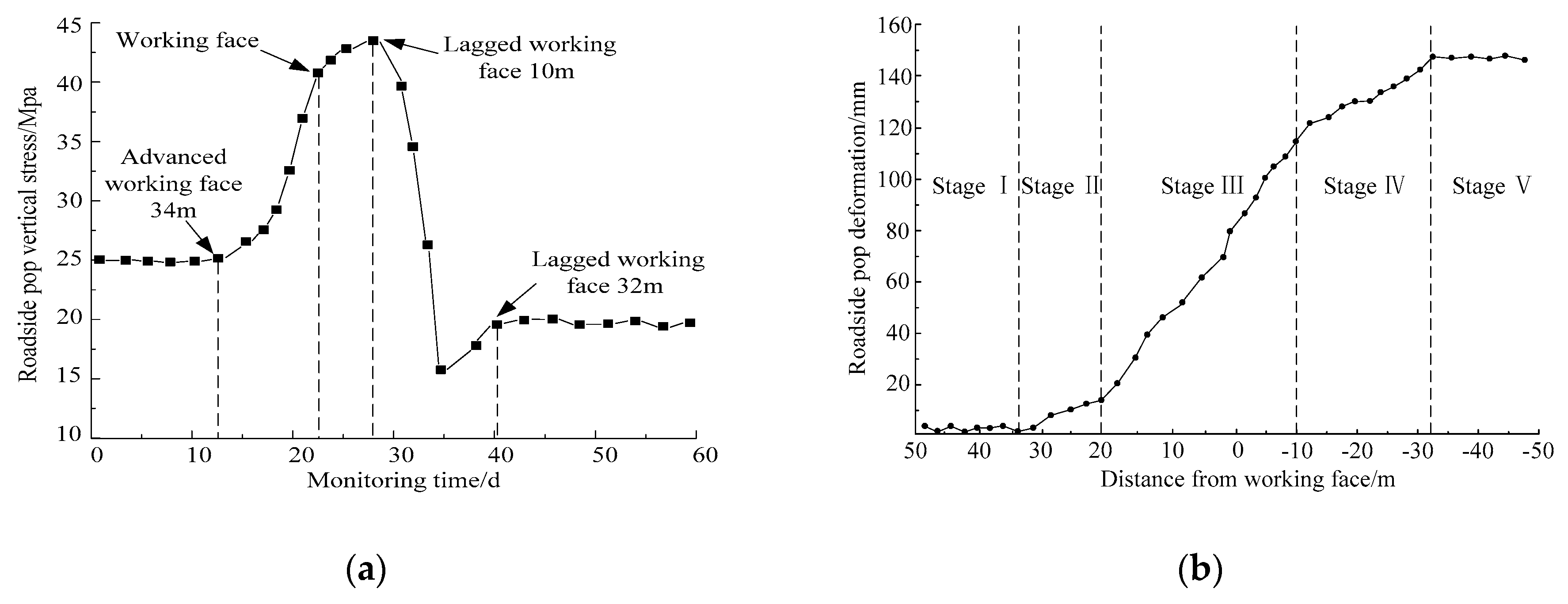
According to the key parameters of roof cutting determined by the above research, field implementation was conducted at No. 2415 headentry in the Suncun coal mine. As the change in the roadside prop can directly reflect the roof and floor movement, the roadside prop stress and displacement are monitored separately to analyse the roof cutting effect. The monitoring curves of roadside prop are shown in Figure 18.
As illustrated in Figure 18a, the influence range of the advanced abutment pressure is approximately 34 m ahead of the working face. Under advanced abutment pressure, the roadside prop increases sharply from 25 to 43 MPa within 20 m ahead of the working face. When the measuring points lag working face by approximately 10 m, the stress on the roadside prop decreases rapidly and reaches approximately 16 MPa. Subsequently, there is a slight increase in stress, which is then stabilised at 19 MPa at approximately 32 m behind working face. As shown in Figure 18b, the displacement monitoring curve of roadside prop can be divided into five stages. Stage I: Within the range of 50–34 m ahead of the working face, the displacement of the roadside prop is small and basically unchanged. At this time, the gob-side entry is not affected by the working face excavation. Stage II: At approximately 34 m ahead of the working face, the displacement of the roadside prop begins to increase. At this time, the deformation rate is small, and the roadside prop deforms slowly. Stage III: When the distance reaches approximately 20 m, the deformation rate increases sharply, and the displacement increases significantly from 18 to 120 mm. Stage IV: At approximately 10–32 m behind the working face, the deformation rate of the roadside prop slows down, and displacement increases slowly. Stage V: The displacement of the roadside prop remains stable at approximately 32 m behind the working face and the displacement after stabilisation is 145 mm.
It can be concluded that within the range of 34 m ahead of the working face, the stress and displacement of the roadside prop begin to increase, from which it can be inferred that this range is the area affected by the advance abutment pressure. After the working face is excavated, the displacements of roadside props are continuously monitored. Within 10 m behind the working face, a large deformation of the surrounding rock occurs owing to the main roof rotary subsidence. Beyond 10 m lagged the working face, the hanging roof collapses along the cutting line under the periodic roof pressure. The gangues in goaf exert the bearing capability on the roof, which reduces the stress of the roadside prop and slows down its deformation rate. Then, as the main roof continues to rotate and sink, the gangues in the goaf are gradually compacted, and the stress of roadside prop increases slightly and eventually stabilises.
The monitoring results show that the stress and displacement of the roadside props are small, which indicates that the hanging roof is effectively cut off after the excavation of the working face, and the roof-cutting effect is remarkable. It also reflects that the deformation of the roof and floor of the gob-side entry is small, as shown in Figure 19, the surrounding rock has been effectively controlled, and the deformation is small, which meets the normal production requirements.
6. Discussion
In this paper, we theoretically confirmed the necessity and significance of roof cutting using GER technology in coal mines, revealed the influences of the cutting parameters on the stability of the surrounding rocks of the gob-side entry, and determined the optimal values of two key parameters, the cutting angle and height, of a typical deep coal seam in the Suncun coal mine.
Currently, some scholars have built structural mechanical models [53,54,55,56] for roof cutting, such as the transfer rock beam mechanical model [53], mechanical model of fracturing roofs to maintain entry approach [54], dynamic pressure area mechanical model [55], and main roof breaking upon retracement channel mechanical model [56]. These mechanical models revealed the role of various supporting structures, such as roadside backfill and coal support, and the basic characteristics of the main roof movement in GER. However, these mechanical models are mainly focused on the after-roof-cutting mechanical analysis. In this paper, the significance and necessity of roof cutting were clarified by establishing two mechanical models of non-roof-cutting and roof-cutting conditions. We deduced the stress and displacement of the roadside prop in the two models according to the theoretical mechanics and material mechanics. This method laid a theoretical foundation for roof cutting in GER.
In addition, the roof cutting parameters play a significant role in the process of roof cutting. Currently, roof cutting parameters are mostly based on field engineering experience or empirical formulas [54,55,56], which limit its application scope. Moreover, the FLAC3D software is used to determine the parameters of roof cutting [57,58]. However, as compared with the FEM, the DEM can not only reflect the fractured form of deep roadway, but also show the failure process of surrounding rock. In this paper, we obtained the optimal roof cutting parameters for No. 2415 headentry of Suncun coal mine by using UDEC numerical simulation software and obtained better application. Additionally, the variable-controlling approach was applied in the process of optimization. In this approach, firstly, we kept vertical cutting height constant, and changed the cutting angle to obtain its optimal angle. Then, we maintained the optimal constant cutting angle and varied cutting heights to obtain the optimal height eventually. This approach avoids blindness in choosing roof-cutting schemes, fully considers the factors of cutting angle and height, and provides references for similar mining conditions.
It should be noted that we only impose a constant static load on the upper boundary of the model without considering the influence of the dynamic load inside the numerical model, which also has great influence to the stability of the surrounding rock in GER [27,28,43]. In addition, the discontinuities have a direct impact on the mechanical properties of the rock mass. Although the mechanical properties of the rock mass are appropriately modified, it is difficult to characterise the mechanical behaviour of the discontinuities in complex geological conditions. In future work, we intend to study the UDEC numerical simulation model further, and gradually improve the design scheme of the key roof cutting parameters in order to make it more widely used.
7. Conclusions
The aim of this research was to confirm the necessity and significance of roof cutting theoretically and determine the optimal values of two key parameters (cutting angle and height), by establishing UDEC numerical models. As compared with the current published works, this work has at least two original aspects:
- Two mechanical models of gob-side entry for non-roof-cutting and roof-cutting cases were established, and the necessity and significance of roof cutting for GER were theoretically revealed.
- The UDEC numerical simulation software was used to simulate the roof cutting process. The key parameters of roof cutting (cutting angle and height) were quantitatively determined by comparing and analysing the simulation results.
With respect to theory, the stress and displacement of the roadside prop were reduced after the roof cutting, which proved the necessity and importance of roof cutting for the surrounding rock stability.
The simulation results showed that cutting angle and height had a significant influence on the surrounding rock stability. (1) As the cutting angle decreased, the amount of stress and displacement at the coal wall and roadside prop decreased first and then increased. When the cutting angle was 70°, the stress and displacement the at coal wall and roadside prop were the smallest. The vertical peak stress values were 10.56 and 20.15 MPa, respectively, i.e., 12.9% and 40.3% lower than those at the cutting angle of 90°. The horizontal displacement of the coal wall and vertical displacement of the roadside prop were 275 and 270 mm, respectively, which were 23.6% and 18.2% less than those at the cutting angle of 90°. When the cutting angle was 50°, the stress at the coal wall and roadside prop increased by 8.4% and 46.1%, respectively, as compared with those at the cutting angle of 70°, and the coal wall horizontal displacement and the roadside prop vertical displacement increased by 23.6% and 18.5%, respectively. (2) As the cutting height increased, the amount of stress and displacement at the coal wall and roadside prop also decreased first and then increased. When the cutting height is 8 m, the stress and displacement at the coal wall and roadside prop are the least, and the vertical peak stress values were 8.82 and 19.87 MPa, respectively, which were 20.7% and 42.3% lower than those at the cutting height of 3 m. The coal wall horizontal displacement and roadside prop vertical displacement were 162 and 150 mm, respectively, which were 53.7% and 55.9% less than those at the cutting height of 3 m. When the cutting height was 50°, the stress at the coal wall and roadside prop increased by 15.1% and 18.9%, respectively, as compared with those at the cutting height of 8 m, and the horizontal displacement of the coal wall and vertical displacement of the roadside prop increased by 38.3% and 40.0%, respectively. Therefore, it can be observed that the influence of the cutting height is more significant than the cutting angle at the selected level, and the optimum cutting parameters can be determined as a cutting angle of 70° and cutting height of 8 m.
Field practice and the monitoring results showed that the stress of the roadside prop increased first and then decreased, and finally stabilised at 19 MPa with a slight rise at 32 m behind the working face. The deformation rate of the roadside prop increased from small to large, then became small, and finally stabilised at 145 mm, which is consistent with the numerical simulation results. The monitoring results showed that the stress transmission inside the immediate roof was fundamentally eliminated on applying the optimal roof cutting parameters determined in the numerical simulation. In addition, the gangues cut down from the main roof filled the goaf according to the dilatancy of the rock, such that it could limit the movement of the main roof and the overlying strata. The stress and displacement of the roadside prop were small, which effectively controlled the deformation and failure of the surrounding rock.
Although the optimal key parameters of the roof were determined, and good field application results have been achieved, it should be noted that the influence of the dynamic load is not taken into consideration in this numerical simulation. In future work, this factor will be taken into consideration, which could make the key parameters more widely applicable.
Author Contributions
Conceptualization, D.F. and X.L.; methodology, D.F. and X.L.; validation, L.Y.; formal analysis, D.F.; investigation, S.S. and Q.X.; software, D.F.; resources, L.Y.; writing—original draft preparation, D.F.; writing—review and editing, X.L.; supervision, Y.T. and Q.G.; project administration, X.L. and Y.T.; funding acquisition, X.L. and Y.T.
Funding
This study was supported by National Key R&D Program of China (No. 2018YFC0604703), National Natural Science Foundation of China (Nos. 51804181, 51874190, and 51574154), Major Program of Shandong Province Natural Science Foundation (No. ZR2018ZA0603), Shandong Province Natural Science Fund (No. ZR2018QEE002), Research Fund of The State Key Laboratory of Coal Resources and Safe Mining, CUMT (No. SKLCRSM18KF014), and Scientific Research Foundation of Shandong University of Science and Technology for Recruited Talents (No. 2017RCJJ008).
Acknowledgments
The authors gratefully acknowledge the financial support from the National Key R&D Program of China (No. 2018YFC0604703), National Natural Science Foundation of China (Nos. 51804181, 51874190, and 51574154), Major Program of Shandong Province Natural Science Foundation (No. ZR2018ZA0603), Shandong Province Natural Science Fund (No. ZR2018QEE002), Research Fund of The State Key Laboratory of Coal Resources and Safe Mining, CUMT (No. SKLCRSM18KF014), and Scientific Research Foundation of Shandong University of Science and Technology for Recruited Talents (No. 2017RCJJ008).
Conflicts of Interest
The authors declare no conflicts of interest.
References
- Song, Z.Q.; Cui, Z.D.; Tang, J.Q.; Wen, Z.J. The fundemental theoretial and engineering research on the green safe no coal pillar mining model by mainly using coal gangue backfill. J. Chin. Coal Soc. 2010, 35, 705–710. [Google Scholar]
- Tan, Y.L.; Yu, F.H.; Ning, J.G.; Zhao, T.B. Design and construction of entry retaining wall along a gob side under hard roof stratum. Int. J. Rock Mech. Min. Sci. 2015, 77, 115–121. [Google Scholar] [CrossRef]
- Su, H.; Bai, J.B.; Yan, S.; Chen, Y.; Zhang, Z.Z. Study on gob-side entry retaining in fully-mechanized longwall with top-coal caving and its application. Int. J. Min. Sci. Technol. 2015, 25, 503–510. [Google Scholar] [CrossRef]
- Kang, H.P.; Niu, D.L.; Zhang, Z.; Lin, J.; Li, Z.H.; Fan, M.J. Deformation characteristics of surrounding rock and supporting technology of gob-side entry retaining in deep coal mine. Chin. J. Rock Mech. Eng. 2010, 29, 1977–1987. [Google Scholar]
- Meng, F.Z.; Wong, L.N.Y.; Zhou, H.; Yu, J.; Cheng, G.T. Shear rate effects on the post-peak shear behaviour and acoustic emission characteristics of artificially split granite joints. Rock Mech. Rock Eng. 2019, 19, 1–20. [Google Scholar] [CrossRef]
- Zhang, N.; Han, C.L.; Kan, J.G.; Zheng, X.G. Theory and practice of surrounding rock control for pillarless gob-side entry retaining. J. Chin. Coal Soc. 2014, 39, 1635–1641. [Google Scholar]
- Liu, X.S.; Ning, J.G.; Tan, Y.L.; Xu, Q.; Fan, D.Y. Coordinated supporting method of gob-side entry retaining in coal mines and a case study with hard roof. Geomech. Eng. 2018, 15, 1173–1182. [Google Scholar]
- Bai, J.B.; Shen, W.L.; Guo, G.L.; Wang, X.Y.; Yu, Y. Roof deformation, failure characteristics, and preventive techniques of gob-side entry driving heading adjacent to the advancing working face. Rock Mech. Rock Eng. 2015, 48, 2447–2458. [Google Scholar] [CrossRef]
- Yang, H.Y.; Cao, S.G.; Wang, S.Q.; Fan, Y.C.; Wang, S.; Chen, X.Z. Adaptation assessment of gob-side entry retaining based on geological factors. Eng. Geol. 2016, 209, 143–151. [Google Scholar] [CrossRef]
- Tan, Y.L.; Gu, Q.H.; Ning, J.G.; Liu, X.S.; Jia, Z.C.; Huang, D.M. Uniaxial compression behavior of cement mortar and its damage-constitutive model based on energy theory. Materials 2019, 12, 1309. [Google Scholar] [CrossRef]
- Wang, P.; Jiang, L.S.; Jiang, J.Q.; Zheng, P.Q. Strata behaviors and rock burst-inducing mechanism under the coupling effect of a hard, thick stratum and a normal fault. Int. J. Geomech. 2018, 18, 1–14. [Google Scholar] [CrossRef]
- Liu, X.S.; Ning, J.G.; Tan, Y.L.; Gu, Q.H. Damage constitutive model based on energy dissipation for intact rock subjected to cyclic loading. Int. J. Rock Mech. Min. Sci. 2016, 85, 27–32. [Google Scholar] [CrossRef]
- Wang, J.; Ning, J.G.; Jiang, J.Q.; Bu, T.T. Structural characteristics of strata overlying of a fully mechanized longwall face: A case study. J. S. Afr. I Min. Metall. 2018, 118, 1195–1204. [Google Scholar] [CrossRef]
- Zhao, Z.H.; Ma, Q.; Chen, S.J.; Ma, H.; Gao, X.J. Prediction model of failure zone in roadway sidewall considering the lithologic effect of rock formation. Math. Probl. Eng. 2018, 2018, 1–12. [Google Scholar] [CrossRef]
- Guo, W.Y.; Zhao, T.B.; Tan, Y.L.; Yu, F.H.; Hu, S.C.; Yang, F.Q. Progressive mitigation method of rock bursts under complicated geological conditions. Int. J. Rock Mech. Min. 2017, 96, 11–22. [Google Scholar] [CrossRef]
- Shreedharan, S.; Kulatilake, P.H.S.W. Discontinuum-equivalent continuum analysis of the stability of tunnels in a deep coal mine using the distinct element method. Rock Mech. Rock Eng. 2015, 49, 1903–1922. [Google Scholar] [CrossRef]
- Komurlu, E.; Kesimal, A.; Demir, S. Experimental and numerical analyses on determination of indirect (splitting) tensile strength of cemented paste backfill materials under different loading apparatus. Geomech. Eng. Int. J. 2016, 10, 775–791. [Google Scholar] [CrossRef]
- Cai, W.; Dou, L.M.; Gong, S.Y.; Li, Z.L.; Yuan, S.S. Quantitative analysis of seismic velocity tomography in rock burst hazard assessment. Nat. Hazards 2015, 75, 2453–2465. [Google Scholar] [CrossRef]
- Wen, Z.J.; Xing, E.R.; Shi, S.S.; Jiang, Y.J. Overlying strata structural modeling and support applicability analysis for large mining-height stopes. J. Loss. Prevent. Proc. 2019, 57, 94–100. [Google Scholar] [CrossRef]
- Zhang, N.; Chen, H.; Chen, Y. An engineering case of gob-side entry retaining in one kilometer-depth soft rock roadway with high ground pressure. J. Chin. Coal Soc. 2015, 40, 494–501. [Google Scholar]
- Zhang, S.; Wang, X.F.; Fan, G.W.; Zhang, D.S.; Cui, J.B. Pillar size optimization design of isolated island panel gob-side entry driving in deep inclined coal seam-case study of Pingmei No.6 coal seam. J. Geophys. Eng. 2017, 15, 816–828. [Google Scholar] [CrossRef]
- Zhao, Y.M.; Zhang, N.; Zheng, X.G.; Li, B.Y. Structural optimization of overlying strata for gob-side entry retaining in 1000 m deep mine with direct thick and hard roof. J. Min. Saf. Eng. 2015, 32, 714–720. [Google Scholar]
- Jiang, B.Y.; Gu, S.T.; Wang, L.G.; Zhang, G.C.; Li, W.S. Strainburst process of marble in tunnel-excavation-induced stress path considering intermediate principal stress. J. Cent. South Univ. 2019, 26, 984–999. [Google Scholar] [CrossRef]
- Singh, G.S.P. Conventional approaches for assessment of caving behaviour and support requirement with regard to strata control experiences in longwall workings. J. Rock Mech. Geotech. Eng. 2015, 7, 291–297. [Google Scholar] [CrossRef] [Green Version]
- Sun, H.H.; Wu, J.; Qiu, Y.X. Rules of ground pressure and strata control in gateways maintained in goaf. J. Chin. Coal Soc. 1992, 17, 15–24. [Google Scholar]
- Kang, H.P.; Wang, G.F.; Jiang, P.F.; Wang, J.C.; Zhang, N.; Jing, H.W.; Huang, B.X.; Yang, B.G.; Guan, X.M.; Wang, Z.G. Conception for strata control and intelligent mining technology in deep coal mines with depth more than 1000 m. J. Chin. Coal Soc. 2018, 43, 1789–1800. [Google Scholar]
- Kang, H.P.; Li, J.Z.; Yang, J.H.; Gao, F.Q. Investigation on the influence of abutment pressure on the stability of rock bolt reinforced roof strata through physical and numerical modeling. Rock Mech. Rock Eng. 2017, 50, 387–401. [Google Scholar] [CrossRef]
- Kang, H.P.; Lou, J.F.; Gao, F.Q.; Yang, J.H.; Li, J.Z. A physical and numerical investigation of sudden massive roof collapse during longwall coal retreat mining. Int. J. Coal Geol. 2018, 188, 25–36. [Google Scholar] [CrossRef]
- Kang, Y.S.; Liu, Q.S.; Gong, G.Q.; Wang, H.C. Application of a combined support system to the weak floor reinforcement in deep underground coal mine. Int. J. Rock Mech. Min. Sci. 2014, 71, 143–150. [Google Scholar] [CrossRef]
- Guo, W.Y.; Tan, Y.L.; Yu, F.H.; Zhao, T.B.; Hu, S.C.; Huang, D.M.; Qin, Z.W. Mechanical behavior of rock-coal-rock specimens with different coal thicknesses. Geomech. Eng. 2018, 15, 1017–1027. [Google Scholar]
- Sun, X.M.; Chen, F.; He, M.C.; Gong, W.L.; Xu, H.C.; Lu, H. Physical modeling of floor heave for the deep-buried roadway excavated in ten degree inclined strata using infrared thermal imaging technology. Tunn. Undergr. Sp. Technol. 2017, 63, 228–243. [Google Scholar] [CrossRef]
- Hua, X.Z.; Li, Y.F. Mechanics analysis on floor deformation of gob-side entry retaining and prevention and control of floor heave. J. Chin. Coal Soc. 2016, 41, 1624–1631. [Google Scholar]
- Liu, X.S.; Tan, Y.L.; Ning, J.G.; Lu, Y.W. Mechanical properties and damage constitutive model of coal in coal-rock combined body. Int. J. Rock Mech. Min. Sci. 2018, 110, 140–150. [Google Scholar] [CrossRef]
- Fang, K.; Zhao, T.B.; Zhang, Y.B.; Qiu, Y.; Zhou, J.H. Rock cone penetration test under lateral confining pressure. Int. J. Rock Mech. Min. 2019, 119, 149–155. [Google Scholar] [CrossRef]
- Feng, X.W.; Zhang, N.; He, F.Z. Implementation of a pre-tensioned, fully bonded, bolting system and its failure mechanism based on acoustic emission: A laboratorial and field study. Geotech. Test. J. 2017, 40, 978–999. [Google Scholar] [CrossRef]
- Chen, Y.; Bai, J.B.; Wang, X.Y.; Ma, S.Q.; Xu, Y.; Bi, T.F.; Yang, H.Q. Support technology research and application inside roadway of gob-side entry retaining. J. Chin. Coal Soc. 2012, 37, 903–910. [Google Scholar]
- He, M.C.; Gong, W.L.; Wang, J.; Qi, P.; Tao, Z.G.; Du, S.; Peng, Y.Y. Development of a novel energy-absorbing bolt with extraordinarily large elongation and constant resistance. Int. J. Rock Mech. Min. Sci. 2014, 67, 29–42. [Google Scholar] [CrossRef]
- Tan, Y.L.; Liu, X.S.; Ning, J.G.; Tian, C.L. Front abutment pressure concentration forecast by monitoring cable-forces in the roof. Int. J. Rock Mech. Min. Sci. 2015, 77, 202–207. [Google Scholar] [CrossRef]
- Yin, Y.C.; Zou, J.C.; Zhang, Y.B.; Qiu, Y.; Fang, K.; Huang, D.M. Experimental study of the movement of backfilling gangues for goaf in steeply inclined coal seams. Arab. J. Geosci. 2018, 11, 1–8. [Google Scholar] [CrossRef]
- Ghirian, A.; Fall, M. Coupled thermo-hydro-mechanical-chemical behaviour of cemented paste backfill in column experiments. Part I: Physical, hydraulic and thermal processes and characteristics. Eng. Geol. 2013, 164, 195–207. [Google Scholar] [CrossRef]
- Gong, F.Q.; Luo, S.; Yan, J.Y. Energy storage and dissipation evolution process and characteristics of marble in three tension-type failure tests. Rock Mech. Rock Eng. 2018, 51, 3613–3624. [Google Scholar] [CrossRef]
- Liu, X.S.; Gu, Q.H.; Tan, Y.L.; Ning, J.G.; Jia, Z.C. Mechanical characteristics and failure prediction of cement mortar with a sandwich structure. Minerals 2019, 9, 143. [Google Scholar] [CrossRef]
- Yin, Y.C.; Zhao, T.B.; Zhang, Y.B.; Tan, Y.L.; Qiu, Y.; Taheri, A.; Jing, Y. An Innovative method for placement of gangue backfilling material in steep underground coal mines. Minerals 2019, 9, 107. [Google Scholar] [CrossRef]
- Chen, S.J.; Wang, H.L.; Zhang, J.W.; Xing, H.L.; Wang, H.Y. Low-strength similar materials for backfill mining: insight from experiments on components and influence mechanism. Geotech. Test. J. 2015, 38, 929–935. [Google Scholar] [CrossRef]
- Koohestani, B.; Belem, T.; Koubaa, A.; Bussièreaet, B. Experimental investigation into the compressive strength development of cemented paste backfill containing Nano-silica. Cem. Concr. Comp. 2016, 72, 180–189. [Google Scholar] [CrossRef]
- Li, M.; Zhang, J.X.; Zhou, N.; Huang, Y.L. Effect of particle size on energy evolution of crushed waste rock in coal mines. Rock Mech. Rock Eng. 2017, 50, 1347–1354. [Google Scholar] [CrossRef]
- Zhang, J.X.; Li, B.Y.; Zhou, N.; Zhang, Q. Application of solid backfilling to reduce hard-roof caving and longwall coal face burst potential. Int. J. Rock Mech. Min. Sci. 2016, 88, 197–205. [Google Scholar] [CrossRef]
- Zhang, J.X.; Zhang, Q.; Sun, Q.; Gao, R.; Deon, G.; Sami, A. Surface subsidence control theory and application to backfill coal mining technology. Environ. Earth Sci. 2015, 74, 1439–1448. [Google Scholar] [CrossRef]
- Tan, Y.L.; Yu, F.H.; Ning, J.G.; Zhao, T.B. Adaptability theory of roadside support in gob-side entry retaining and its supporting design. J. Chin. Coal Soc. 2016, 41, 376–382. [Google Scholar]
- Ning, J.G.; Liu, X.S.; Tan, J.; Gu, Q.H.; Tan, Y.L.; Wang, J. Control mechanisms and design for a ‘coal-backfill-gangue’ support system for coal mine gob-side entry retaining. Int. J. Oil Gas Coal Technol. 2018, 18, 444–466. [Google Scholar] [CrossRef]
- Ning, J.G.; Wang, J.; Liu, X.S.; Qian, K.; Sun, B. Soft-strong supporting mechanism of gob-side entry retaining in deep coal seams threatened by rock burst. Int. J. Min. Sci. Technol. 2014, 24, 805–810. [Google Scholar] [CrossRef]
- Ning, J.G.; Wang, J.; Bu, T.T.; Hu, S.C.; Liu, X.S. An innovative support structure for gob-side entry retention in steep coal seam mining. Minerals 2017, 7, 75. [Google Scholar] [CrossRef]
- He, M.C.; Zhu, G.; Guo, Z. Longwall mining “cutting cantilever beam theory” and 110 mining method in China-The third mining science innovation. J. Rock Mech. Geotech. Eng. 2015, 7, 483–492. [Google Scholar] [CrossRef]
- He, M.C.; Gao, Y.B.; Yang, J.; Gong, W.L. An innovative approach for gob-side entry retaining in thick coal seam longwall mining. Energies 2017, 10, 1785. [Google Scholar] [CrossRef]
- Schumacher, F.P.; Kim, E. Evaluation of directional drilling implication of double layered pipe umbrella system for the coalmine roof support with composite material and beam element methods using FLAC3D. J. Min. Sci. 2014, 50, 335–338. [Google Scholar] [CrossRef]
- Li, S.H.; Zhu, W.C.; Niu, L.L.; Yu, M.; Chen, C.F. Dynamic characteristics of green sandstone subjected to repetitive impact loading: phenomena and mechanisms. Rock Mech. Rock. Eng. 2018, 51, 1921–1936. [Google Scholar] [CrossRef]
- Sun, X.M.; Liu, X.; Liang, G.F.; Wang, D.; Jiang, Y.L. Key parameters of gob-side entry retaining formed by roof cut and pressure releasing in thin coal seams. Chin. J. Rock Mech. Eng. 2014, 33, 1449–1456. [Google Scholar]
- Yan, S.; Liu, T.X.; Bai, J.B.; Wu, W.D. Key parameters of gob-side entry retaining in a gassy and thin coal seam with hard roof. Processes 2018, 6, 51. [Google Scholar] [CrossRef]
- Fairhurst, C.E.; Hudson, J.A. Draft ISRM suggested method for the complete stress-strain curve for intact rock in uniaxial compression. Int. J. Rock Mech. Min. Sci. 1999, 36, 281–289. [Google Scholar]
- Itasca Consulting Group, Inc. UDEC User Manual; Itasca Consulting Group, Inc.: Minneapolis, MN, USA, 2008. [Google Scholar]
- Kazerani, T.; Zhao, J. Micromechanical parameters in bonded particle method for modelling of brittle material failure. Int. J. Numer. Anal. Met. 2010, 34, 1877–1895. [Google Scholar] [CrossRef]
Figure 1.
Layout of mine location and 2415 working face.

Figure 2.
Histogram of 2# coal seam and its roof-and-floor rock strata.

Figure 3.
Surrounding rock deformation and failure in No. 2415 headentry. (a) Coal wall deformation; (b) Roof deformation.
Figure 3.
Surrounding rock deformation and failure in No. 2415 headentry. (a) Coal wall deformation; (b) Roof deformation.

Figure 4.
Uniaxial compression test and stress-strain curves for the rock mass. (a) Schematic picture of Shimadzu AG-X250 electronic universal testing machine; (b) Axial stress-strain curves of uniaxial compression test on fine sandstone.
Figure 4.
Uniaxial compression test and stress-strain curves for the rock mass. (a) Schematic picture of Shimadzu AG-X250 electronic universal testing machine; (b) Axial stress-strain curves of uniaxial compression test on fine sandstone.

Figure 5.
Mechanical model for GER (gob-side entry retaining). (a) Non-roof-cutting; (b) Roof-cutting.
Figure 5.
Mechanical model for GER (gob-side entry retaining). (a) Non-roof-cutting; (b) Roof-cutting.

Figure 6.
Mohr–Coulomb failure criterion for block in UDEC [60].
Figure 6.
Mohr–Coulomb failure criterion for block in UDEC [60].

Figure 7.
The constitutive behavior of the contact [61].
Figure 7.
The constitutive behavior of the contact [61].

Figure 8.
Numerical model and boundary conditions.

Figure 9.
Flowchart of numerical modeling for optimal roof cutting parameters.

Figure 10.
Numerical simulation schemes for different cutting angles. (a) Cutting angle 90°; (b) Cutting angle 80°; (c) Cutting angle 70°; (d) Cutting angle 60°; (e) Cutting angle 50°.
Figure 10.
Numerical simulation schemes for different cutting angles. (a) Cutting angle 90°; (b) Cutting angle 80°; (c) Cutting angle 70°; (d) Cutting angle 60°; (e) Cutting angle 50°.


Figure 11.
Numerical calculation results of vertical stress contours for different cutting angles. (a) Cutting angle 90°; (b) Cutting angle 80°; (c) Cutting angle 70°; (d) Cutting angle 60°; (e) Cutting angle 50°.
Figure 11.
Numerical calculation results of vertical stress contours for different cutting angles. (a) Cutting angle 90°; (b) Cutting angle 80°; (c) Cutting angle 70°; (d) Cutting angle 60°; (e) Cutting angle 50°.


Figure 12.
Monitoring points curves after excavation for different cutting angles. (a) Coal wall vertical stress; (b) Coal wall horizontal displacement; (c) Roadside prop vertical stress; (d) Roadside prop vertical displacement.
Figure 12.
Monitoring points curves after excavation for different cutting angles. (a) Coal wall vertical stress; (b) Coal wall horizontal displacement; (c) Roadside prop vertical stress; (d) Roadside prop vertical displacement.

Figure 13.
Numerical simulation results for different cutting angles. (a) Coal wall vertical stress, MPa; (b) Coal wall horizontal displacement, mm; (c) Roadside prop vertical stress, MPa; (d) Roadside prop vertical displacement, mm.
Figure 13.
Numerical simulation results for different cutting angles. (a) Coal wall vertical stress, MPa; (b) Coal wall horizontal displacement, mm; (c) Roadside prop vertical stress, MPa; (d) Roadside prop vertical displacement, mm.


Figure 14.
Numerical simulation schemes for different cutting heights. (a) Cutting height 3 m; (b) Cutting height 4 m; (c) Cutting height 6 m; (d) Cutting height 7 m; (e) Cutting height 8 m; (f) Cutting height 9 m.
Figure 14.
Numerical simulation schemes for different cutting heights. (a) Cutting height 3 m; (b) Cutting height 4 m; (c) Cutting height 6 m; (d) Cutting height 7 m; (e) Cutting height 8 m; (f) Cutting height 9 m.

Figure 15.
Numerical calculation results of vertical stress distributions for different cutting heights. (a) Cutting height 3 m; (b) Cutting height 4 m; (c) Cutting height 6 m; (d) Cutting height 7 m; (e) Cutting height 8 m; (f) Cutting height 9 m.
Figure 15.
Numerical calculation results of vertical stress distributions for different cutting heights. (a) Cutting height 3 m; (b) Cutting height 4 m; (c) Cutting height 6 m; (d) Cutting height 7 m; (e) Cutting height 8 m; (f) Cutting height 9 m.

Figure 16.
Monitoring points curves after excavation for different cutting heights. (a) Coal wall vertical stress; (b) Coal wall horizontal displacement; (c) Roadside prop vertical stress; (d) Roadside prop vertical displacement.
Figure 16.
Monitoring points curves after excavation for different cutting heights. (a) Coal wall vertical stress; (b) Coal wall horizontal displacement; (c) Roadside prop vertical stress; (d) Roadside prop vertical displacement.

Figure 17.
Numerical simulation results for different cutting heights. (a) Coal wall vertical stress, MPa; (b) Coal wall horizontal displacement, mm; (c) Roadside prop vertical stress, MPa; (d) Roadside prop vertical displacement, mm.
Figure 17.
Numerical simulation results for different cutting heights. (a) Coal wall vertical stress, MPa; (b) Coal wall horizontal displacement, mm; (c) Roadside prop vertical stress, MPa; (d) Roadside prop vertical displacement, mm.

Figure 18.
Roadside prop monitoring curves. (a) Vertical stress monitoring curve; (b) Deformation monitoring curve.
Figure 18.
Roadside prop monitoring curves. (a) Vertical stress monitoring curve; (b) Deformation monitoring curve.

Figure 19.
Effects of the surrounding rock control in No. 2415 headentry. (a) Cutting line at gob-side; (b) Roof deformation; (c) Roadside prop deformation; (d) Gangues retaining along gob-side.
Figure 19.
Effects of the surrounding rock control in No. 2415 headentry. (a) Cutting line at gob-side; (b) Roof deformation; (c) Roadside prop deformation; (d) Gangues retaining along gob-side.


Table 1.
Mechanical properties used in the UDEC model.
| Lithology | Matrix Properties | Contact Properties | |||||
|---|---|---|---|---|---|---|---|
| Density (kg/m3) | E* (GPa) | kn* (GPa/m) | ks* (GPa/m) | Cohesion (MPa) | Friction (°) | Tensile Strength (MPa) | |
| Mudstone | 1900 | 12.7 | 79.2 | 31.7 | 5.6 | 16 | 1.1 |
| Shale | 2100 | 16.0 | 160 | 64 | 2.7 | 15 | 0.8 |
| Sandy mudstone | 2500 | 17.0 | 76.8 | 6.8 | 6.0 | 21 | 2.0 |
| Middle sandstone | 2300 | 15.2 | 120 | 24.3 | 10.1 | 22 | 2.4 |
| Limestone | 2200 | 14.2 | 49.7 | 43.2 | 3.8 | 19 | 1.6 |
| Fine sandstone | 2600 | 16.4 | 55.6 | 20.8 | 11.3 | 21 | 2.2 |
| Siltstone | 2400 | 18.0 | 48.4 | 15.4 | 9.5 | 20 | 2.5 |
| Coal | 1400 | 12.8 | 84 | 33.6 | 4.6 | 18 | 1.0 |
© 2019 by the authors. Licensee MDPI, Basel, Switzerland. This article is an open access article distributed under the terms and conditions of the Creative Commons Attribution (CC BY) license (http://creativecommons.org/licenses/by/4.0/).
Share and Cite
MDPI and ACS Style
Fan, D.; Liu, X.; Tan, Y.; Song, S.; Gu, Q.; Yan, L.; Xu, Q. Roof Cutting Parameters Design for Gob-Side Entry in Deep Coal Mine: A Case Study. Energies 2019, 12, 2032. https://doi.org/10.3390/en12102032
AMA Style
Fan D, Liu X, Tan Y, Song S, Gu Q, Yan L, Xu Q. Roof Cutting Parameters Design for Gob-Side Entry in Deep Coal Mine: A Case Study. Energies. 2019; 12(10):2032. https://doi.org/10.3390/en12102032
Chicago/Turabian StyleFan, Deyuan, Xuesheng Liu, Yunliang Tan, Shilin Song, Qingheng Gu, Lei Yan, and Qiang Xu. 2019. "Roof Cutting Parameters Design for Gob-Side Entry in Deep Coal Mine: A Case Study" Energies 12, no. 10: 2032. https://doi.org/10.3390/en12102032
Note that from the first issue of 2016, this journal uses article numbers instead of page numbers. See further details here.