Article

ERIGrid Holistic Test Description for Validating Cyber-Physical Energy Systems

1
Technical University of Denmark, DK2800 Kgs. Lyngby, Denmark
2
OFFIS—Institute for Information Technology, 26121 Oldenburg, Germany
3
Institute for Energy and Environment, Electronic and Electrical Engineering Department, University of Strathclyde, Glasgow G1 1XW, UK
4
CEA, LITEN, Department of Solar Technologies INES, University Grenoble Alpes, F-73375 Le Bourget du Lac, France
5
SINTEF Energi AS, 7034 Trondheim, Norway
6
Tecnalia Research & Innovation, 48160 Derio, Spain
7
Vestas Wind Systems A/S, DK8200 Aarhus, Denmark
8
AIT Austrian Institute for Technology—Electric Energy Systems, Center for Energy, 1210 Vienna, Austria
*
Author to whom correspondence should be addressed.
Energies 2019, 12(14), 2722; https://doi.org/10.3390/en12142722
Submission received: 13 June 2019 / Revised: 10 July 2019 / Accepted: 11 July 2019 / Published: 16 July 2019
(This article belongs to the Special Issue Energy-Aware Cyber-Physical Systems)

Abstract

:
Smart energy solutions aim to modify and optimise the operation of existing energy infrastructure. Such cyber-physical technology must be mature before deployment to the actual infrastructure, and competitive solutions will have to be compliant to standards still under development. Achieving this technology readiness and harmonisation requires reproducible experiments and appropriately realistic testing environments. Such testbeds for multi-domain cyber-physical experiments are complex in and of themselves. This work addresses a method for the scoping and design of experiments where both testbed and solution each require detailed expertise. This empirical work first revisited present test description approaches, developed a newdescription method for cyber-physical energy systems testing, and matured it by means of user involvement. The new Holistic Test Description (HTD) method facilitates the conception, deconstruction and reproduction of complex experimental designs in the domains of cyber-physical energy systems. This work develops the background and motivation, offers a guideline and examples to the proposed approach, and summarises experience from three years of its application.

1. Introduction

With Smart Energy (The term Smart Energy is used to represent the fields of smart grids and multi-energy systems, as Cyber-Physical Energy Systems (CPES), emphasising an increasing reliance of Information and Communication Technology (ICT).) solutions reaching higher technology readiness [1], the question of appropriate testing becomes pressing [2]. Testing is necessary throughout development as well as before roll-out of market-ready products [3], employing virtual, physical, and hybrid testbeds [4,5]. A key issue for testing of smart energy solutions is their mixed-technology nature involving communications, controls, and multi-domain physical infrastructure, which affects both availability of engineering expertise and suitable tool integration [6].
An appropriate test is then an issue of sufficiently clear test objectives and a specific and relevant multi-domain test environment [3,6,7]. The standards for technical quality and appropriate levels of scrutiny in testing are set within the specific context of a scientific discipline or technical application domain. For example, organisations within automotive, thermal systems or electric power domains each identify and maintain their specific standards, test requirements, protocols and test environments.
For a project coordinator, system integrator, solution developer, test engineer, or researcher, a project aim often is to increase the Technology Readiness Level (TRL) [2] of a specific smart energy solution. Rather than development, the ultimate project aim would thus be a validation goal, marked by a successful test or demonstration. The counterpart to this validation is posed by the project funder or other stakeholders, who may seek documentation of tests or tracing of requirements to test results. The requirements description by means of use cases and Smart Grid Architecture Model (SGAM) modeling [8,9] is now established practice in smart energy projects (DISCERN, ELECTRA IRP, SmartNet, TDX-Assist, ID4L, etc. [10]), However, the reporting on tests and demonstrations that form the critical milestone of such projects are less well structured due to a lack of suitable and standardised methods. R&D projects could improve their impact by planning from a validation ambition formulated as test cases, which would directly relate the project’s main use cases and the desired TRL level. A clear, formalisable test description may help overcome the increasing complexity emerging from both multi-domain systems solutions and the increasingly complex experimental platforms, by improving re-use, accelerating test preparation and execution, and enabling reproducibility. Already a harmonisation of test descriptions would facilitate re-use relevant in industrial settings, reproducibility in a research setting, and generally the potential for knowledge sharing across disciplines and laboratories.

1.1. Challenges in Testing of Cyber-Physical Energy Systems

Appropriate tests for multi-domain systems are harder to plan than tests within established disciplinary boundaries. Consider that solutions in the field of Smart Energy Systems, as for example a Distributed Energy Resource Management (DERM) application [11,12], tend to encompass multiple disciplines (ICT, automation, physical infrastructure) and affect several physical domains (electricity, heating, energy storage, etc.), with causal interactions and feedback loops spanning across disciplines and domains. Experiments for the characterisation of relevant aspects and validation of each DERM system function will have to consider functional and structural qualities of each discipline, as well as their interactions.
Experimental platforms are being enhanced and interconnected in an effort to address the testing needs in Smart Energy: multi-disciplinary simulation and co-simulation, interconnection of facilities, integrated physical and real-time simulation experiments, and remote laboratory integration. An example is a geographically distributed real-time experimental setup across continents to assess the integration of wind farms in large scale grids [13]. By integrating facilities, a Power Hardware-in-the-Loop (PHIL) testing infrastructure was remotely connected to larger-scale electric grid models to validate the performance of two residential-scale advanced solar inverters [14].

1.2. Possible Harmonisation

Thus, the complexity of multi-domain systems and their required experimental platforms are both growing. As a result, the disciplinary and methodological framing of experiments is becoming a challenge itself. This methodological framing, however, would have to be independent from engineering disciplines, as well as from the experimental platform. Despite differences in practice between disciplines and domains, some distinct aspects of testing are identifiable across disciplines: (i) what is tested and why; (ii) the test elements and test protocol; and (iii) the physical or virtual facility (from here on: testbed) employed to realise the experiment.
Given these distinctions, experiment descriptions (Note that the terms “experiment” and “test” are used interchangeably. From a platform and execution point of view, the only difference between experiment and test is in the outcome judgement: an experiment is aimed to increase knowledge (qualify, characterise, and identify), while a test assesses some pass/fail criterion (verify and validate).) can be harmonised at a higher level of abstraction. For instance, in application to ICT systems, the European Telecommunications Standards Institute (ETSI) standardisation body has developed a suite of standards including a test purpose language, explicit Test Description Language (TDL), where its syntax is required to be concretised for individual domain application [15]. While working at a higher abstraction level allows transfer between instances and harmonisation of equivalents between these, there is necessarily a greater gap between the abstract description of a test and its implementation. This “specification gap” arises in the preparation of experiments, and becomes all the more significant with increasing complexity of cyber-physical system structure of solutions and advancements in testbed technology.

1.3. Scope and Approach

This work aims to address the above described gap concerning the following questions:
(a) 
How can experiments be framed to account for the multi-disciplinary setting and wide variety of employed experimental platforms?
(b) 
To what extent can a template-based approach to experiment description enhance the quality of experiment planning, experiments, and reporting?
We are interested in facilitating the scoping and design of validation tests and experiments by offering a better formal framing and a procedural guideline. In this work, we focus on the preparation of technically “holistic” test descriptions (characterised by a multi-domain and systems-of-systems view towards a formalised description covering design and validation) with application to Smart Energy problems, and report its use in a number of cases. The presented approach in this article has been developed in the European ERIGrid project [16] and an early version of it was already discussed in [7,17].
The remainder of this article is structured as follows: Section 2 indentifies the context and background of test description methods. Section 3 provides a thorough guideline to the HTD approach and Section 4 provide an illustrative example and reports on HTD applications. Finally, Section 5 concludes this article.
For readers focused on the applying the HTD in their own work, we refer to Section 2.2 for context, Section 3 for the guidelines, and Section 4.1 for the discussion of an application example.

2. Background and Related Work

To achieve a holistic view on test descriptions, we ought to be aware of their full context, in terms of related work (Section 2.1) purpose, formal context, technology (testbeds), and methodology (test procedures). This requires separately examining the purpose of testing in a formal context (Section 2.2), the application to the energy system context (Section 2.3), and how this connection implies requirements for both testing technology and methodology (Section 2.4 and Section 2.5).

2.1. Related Work

A related work in the smart energy domain is the interoperability testing methodology proposed in [18]. ETSI defines a set of standards which have a similar semantic structure as the here proposed holistic test description: The ETSI Test Purpose Language (TPLan) [19], Test Description Language (TDL) [20], and Testing and Test Control Notation Version 3 (TTCN-3) [21] together offer an abstract language for describing a test purposes, context, test system and interfaces to the software under test. TTCN-3 is notable for abstracting the test execution semantics from the test execution platform. Compared to the present work, the limitation of the ETSI collection of standards is its restriction to the ICT domain.
Several projects in the field of smart energy have applied and adopted variants of the here outlined methodology, including the SmILES, ELECTRA-IRP, and SmartNet projects, as discussed in Section 4.3.

2.2. Test Purposes: Testing in a Technical Development Context

Experiments play a role in the early stages of a technical design as well as in the final stages where technical solutions are evaluated against technical specifications and system level requirements. In early design, experiments can be employed (e.g., to inform the selection of design parameters, such as to characterise the performance of a heat pump) under expected operating conditions. In the construction of a solution, experiments are carried out to validate whether aspects of a solution live up to the requirements (e.g., “Can the control system performance be maintained with a given communication channel?”). Systems design processes in industry follow the general scheme of the V-model [22].
The V-model allows conceptualising the hierarchy and context of technical experiments (tests) for iterative product validation are shown as a staged top-down and bottom-up process from left to right in Figure 1. In the top-down phase, the project is decomposed in multiple sub-projects at different levels of requirements specification and system granularity. This decomposition enables parallel development of sub-systems and components, while tracing requirements to overall system purposes. The bottom-up phase represents the validation and integration of different solution aspects and sub-systems. This V-model can be interpreted classically as “waterfall” sequential process, but can also be applied to modern concurrent engineering as a conceptual hierarchy, where the V-model establishes a strong coupling of requirements specification and testing: at every stage of development, experiments are based on: (a) requirements identified earlier in the design process (i.e., in the top-down phase); (b) an assembly of components validated in a previous stage of testing; and (c) the appropriate type of testbed (dark red in Figure 1).
The relation between system requirements and test specification, as well as their widening specification gap, is also visible in this illustration of the V-model. This specification gap appears at higher levels of integration, and is amplified when the test involves the integration of several domains with fundamentally distinct natures (e.g., power system and ICT).
In engineering and research practice, the conceptual difference between design and testing is easily obscured at early development stages, with improved use of simulations and software tool integration. In (simulation-based) design, the focus is on structural and parametric changes to a (simulation) model, which lead to an incremental adaptation of a system design. In contrast, for testing, the system is fixed, and an experiment is set up to quantify a property or to validate a hypothesis (e.g., function and performance) about the present system design. As the system grows in scale and complexity, the formulation of a test hypothesis also becomes non-trivial; on the one hand, it is driven by the (more complex) system requirements, but larger and more complex experimental setups are required.
A holistic test description would support this re-framing from engineering design to test design, helping to narrow down the test purpose and test system requirements.

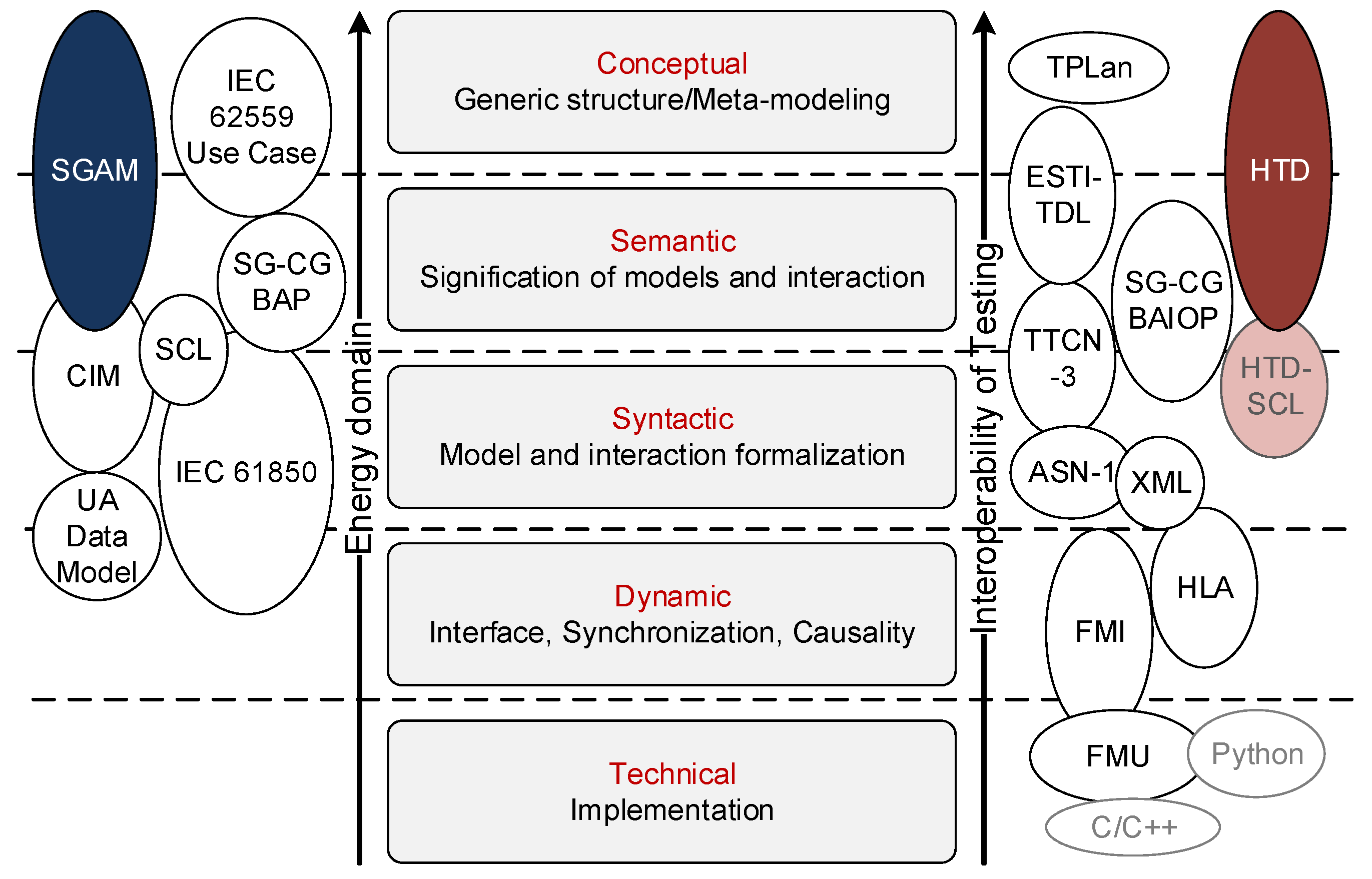
2.3. The Relation between Testing and Energy System Semantics

The essence of framing an experiment is therefore in the formulation of a test hypothesis. In CPES, two key aspects of a test hypothesis are the boundary of the test system and the system qualities to be assessed. System qualities of interest would typically be derived from system requirements or related engineering concerns. For the identification of a system boundary, we have to consider both the system functional and structural architecture, and its environmental embedding. This hypothesis should be developed as independent from the testing tool. Only later in the experiment design, the testbed properties are required to define embedding of a system part being tested into an emulated or simulated experimental environment.
To achieve an operable integration between the different stages and phases of the V-model, we distinguish the semantic context of the energy system solution from the context of testing and embedding in a testing platform. Despite verlapping terminology and tooling between these contexts, each has its own set of engineering requirements and purposes:
(1)
The energy system semantic: It represents the behaviour and the semantic relations among the different actors of the system. Depending on the considered energy system and the information models, this semantic represent the application relevant purposes, components and structures of the system (i.e., the “real world application”).
(2)
The testing semantic: It is the purpose and content of a single or set of tests. It relates the real-world motivation for a test to the concrete system configurations and functions to be included in an experiment.
The aforementioned specification gap (see Figure 1) can now be described by three gaps: (i) the translation between these two semantics; (ii) the lack of testing semantics for the multi-domain nature of a cyber-physical energy system; and (iii) missing semantics and integration for the advanced testing technologies of CPES. At present, this gap is addressed manually by engineers proposing a specific test-setup and validation criteria. The process is therefore subjective and presents difficulties for keeping a common understanding across different stakeholders, test-stages, and for eventual system integration.
Common to both semantics, i.e., (1) and (2), is the sequence of abstraction layers, which can be interpreted in a top-down view from purpose-oriented to implementation-oriented. The layers are listed in Figure 2 along with related standards from the energy system context (left) and testing context (right). In the following, we introduce the left and right side of Figure 2. The complexity and semantics of test technologies, i.e., Gap (iii), is discussed in the next section.

2.3.1. Energy System Semantic

The existing energy system semantics (or information models) on the left side of Figure 2. The common information model (CIM/IEC61970-61968) [23,24], OPC UA data model [25] and IEC 61850 data model [26] are popularly employed in the electrical domain. They cover the functional, semantic, and syntactic configurations of a system while the dynamic and technical configurations are provided by the specific implementation technologies (TCP/IP, modbus, DNP3, etc.). While they can be readily used for system specification, there is a need to improve support for modelling other domains (e.g., ICT and thermodynamics). Nevertheless, the energy system semantics can be used as building blocks for the CPES design but the link from these information models to the validation setup is obscured, hence, the specification gap.
The SGAM proposes an interoperability architecture that covers mainly the conceptual and semantical interactions in a multi-domain smart grid. The link to validation setup in SGAM is presented as a methodology based on use-case reference designation and specifications [27]. The SGAM methodology uses IEC 62559 for energy system design and provided the tailored use case template for this purpose. In this concept, a use case is considered as the basis for defining a system, its functionality and interaction necessary for the experiment design. It involves also the definition of Basic Application Profiles (BAP) and Basic Application Interoperability Profile (BAIOP) as modular elements for specification of system and subsystem. BAP and BAIOP represent the basic building blocks for the CPES, and can provide possible skeletons for setting up interoperability validation experiment [18]. It is however noteworthy that the use-case specifications provided in BAP and BAIOP involves specifically the system/sub-system architecture and it lacks guideline of the test specifications, implementation and technologies.

2.3.2. Testing Semantics

Notable for providing a complete set of testing semantics is the ETSI test description suite, comprising the Test Purpose Language (TPLan) [19], Test Description language (TDL) [20], and the Testing and Test Control Notation Version 3 (TTCN-3). While TPlan provides the objective and purpose of the test regardless to the testing environment, TDL bridges the methodology gap between TPLan and the complex executable semantic below. TPLan and TDL are then translated to TTCN-3. TTCN-3 is at an abstract level specifying, providing templates, syntax, and vocabularies to define a test configuration and procedure; however, a corresponding test system is needed for the execution, i.e., the TTCN-3 semantic needs to be mapped down to an execution platform and can be integrated with system types of other languages (ASN.1, XML, and C/C++). Besides, as a test specification semantic, TTCN-3 requires a domain specified syntax and vocabularies to enable comprehensive communication among its elements. The concept of abstract test suite in TTCN-3 standard [21] represents test descriptions in information technology. By defining formal (standardised) testing semantics and syntax, TTCN-3 enabled test automation [28], a software suit for conformance testing [29], and to promote reusability and possibility for further integration of new elements into the framework [30]. For instance, TPLan, TDL and TTCN-3 are utilised in information domain. However, to apply them to CPES assessment and validation, there is missing a means to establish a concrete link to energy system specifications, as the ETSI suite is not meant to interface physical structures and functions. This gap may be filled by integration of a complementing energy system semantic.
The holistic test description addresses both the energy system semantic and testing semantic, offering specification levels that relate to energy systems use cases and structural descriptions, while offering descriptions levels conceptually similar to those defined in the ETSI suite of TPLan, TDL, and TTCN-3.

2.4. Testbed Technology

The specification gap becomes more apparent when the validation process requires a combination of several testing technologies, each with their associated semantics and interfacing approach. Consider the following range of techniques and tools employed to support testing of CPES:
  • Co-simulation is the concept of composing coupled simulators that cooperate with each other while running on their own solvers and models. Co-simulation is particularly useful for coupling models with different time scales (transient/steady state) or with distinct natures (continuous/discrete event), in eventually different domains (e.g., power and ICT, electric and thermo) [31,32,33].
  • Hardware-in-the-Loop (HIL) is the experimental technique in which a Hardware under Test (HUT) is coupled with a real-time simulation to test under realistic conditions. HIL supports throughout study of transient and steady state operation of the HUT under realistic, yet safe and repeatable, conditions; testing of a HUT in faulty and extreme conditions without damaging laboratory equipment [34,35].
  • Remote laboratory coupling and integration of HIL and co-simulation in a holistic framework [36,37,38,39,40,41,42] enables a more complete and realistic consideration of CPES, and coupling of existing physical labs with simulated environments in an integrated and consistent manner. Architectures have been proposed as supports for such cross-infrastructure deployment: using real-time database as the common interchange point [43], dedicated message bus [37,40], Supervisory Control and Data Acquisition (SCADA) as a service [44], and direct peer-2-peer streams [38] using a real-time protocol. Besides providing the required technical base for implementation, these architectures also pave the way to international collaboration by combining several infrastructures and/or replacing non-available components/systems by simulation, increasing the realism of validation and demonstration environments.
Each of these approaches entails coupling of different testbed contexts. Thus, in addition to increasing complexity of the CPES and complexity of testing semantics noted above, the diversified and rapid advancement of testbed technologies needs to be addressed to encompass the complete test description. Issues here include the establishment of a common information model across the diverse testbed, synchronisation, logging and time-stamping, as well as methods for the coherent initialisation of the test setup.
The holistic test description proposed in this paper is intended to resolve this challenge in part by aiming to fill in the specification gap also at the level of testbed description and mapping of test specifications to testbed.

2.5. Test Design, Sampling and Evaluation Methodology (Design of Experiments)

The statistical concept of Design of Experiments (DoE) has been developed to address result significance and reproducibility in experimentation. The phrase has been coined by Fisher [45] who has established many fundamental concepts of the methodology as well as an abstract terminology that allows DoE to be easily mapped to any application domain. In its essence, DoE provides a statistical framework to explore the influence of different factors on a system’s response. A special focus is put on avoiding the confounding of factors so that their influences can be distinguished from each other. While these basic ideas of DoE had initially found application in agricultural and clinical research, over time they have also been adopted by the engineering domain to improve product optimisation, quality assessment and validation [46,47]. Especially in the context of software simulation, the DoE framework has been widely adopted and modernised by the extension to more complex, multidimensional sampling algorithms [48,49]. Thus far, however, DoE application is mostly limited to research in single engineering domains while strongly interdisciplinary research fields such as CPES have not yet experienced a broad adoption of DoE. An exception is given in [18], where it has been applied to interoperability testing in CPES relation to recent standards developments. Further application of DoE in the field is thus promising.
Concepts of classical, hardware-oriented DoE and modern, simulation-based DoE are often discussed separately from each other. In the CPES domain, however, software- and hardware-based testing exist in one common, continuous validation process with HIL approaches as the link between them. Consequently, CPES applications of DoE require the consideration of all common DoE concepts in combination with each other.
In the course of this work, the authors demonstrate how the DoE methodology can be seen as an intrinsic part of a HTD. It provides testing with the statistical groundwork for efficient experimentation, result reproducibility and significance of the outcome against noise in the tested system. A first discussion of the relationship between DoE and holistic testing has been given in [50]. The work presented in this paper partly builds up on this first approach and aims to provide a more general understanding.

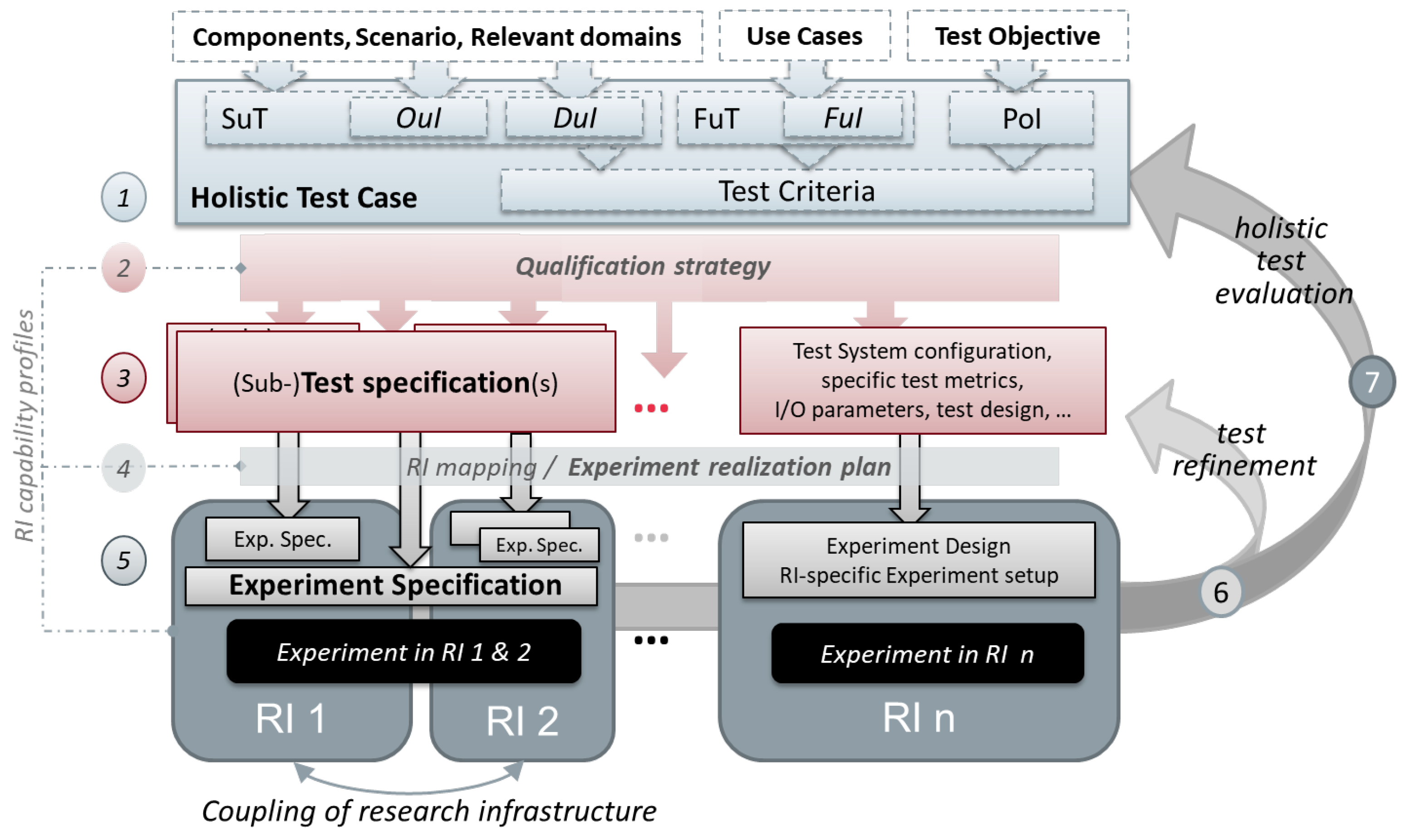
3. Guideline to Holistic Test Description

In practice, test description means to write up intentions and draw out configurations, to identify and define the essential parameters and procedural steps for conducting a test. The HTD aims to support testing and test description practitioners in laying out these intentions in a clear and traceable manner, despite the complexities arising in CPES testing which have been outlined above. The HTD approach comprises a set of textual templates [51], a graphical notation and partial processes that may be employed by a practitioner to structure, refine and document their testing endeavour. The whole process is outlined in Figure 3. As with any model process, the HTD offers a supporting structure and raises relevant questions (For the same reasons it can seem overly formal and tedious to apply when the testing problem is simple. For example, a practitioner who is completely familiar with their laboratory may find little need to follow the steps of an “Experiment Realisation Plan”.). Whereas users have reported benefits from using of HTD templates in early phases of test scoping and planning, the fully documented test description may also be relevant in cases where a complete trace of the experiment design is valued. The supporting structure offered by the HTD has some complexity; for any learner, it can be useful to practice once on a simple problem, to avoid too steep a learning curve during a complex application.
In test applications involving multiple research infrastructures or testbeds, it is unavoidable to follow an approach that likes the here described HTD method, including the development of new testing chains, round robin testing or the online coupling of research infrastructure. Essentially, the HTD provides a framework for separating test-bed test objectives, and supports the qualification of test-beds as part of the testing approach. It is expected that a minimal HTD use is beneficial in any multi-disciplinary testing effort.
The following sections provide a modular overview of the HTD approach, enabling readers to quickly grasp the purpose of different parts of the HTD and assess which of them will be more applicable in their test. First, Section 3.1 provides an overview of the elements, and then Section 3.2 highlights important aspects of the HTD in more detail.

3.1. Overview of HTD Elements

A common point of departure in applying the HTD should always be the formulation of a Test Case, with its elements outlined in Figure 4. The HTD comprises further steps, reducing abstraction to the implementation in a physical or virtual testbed.
The steps and elements on the path to implementation of an experiment are outlined here in their logical sequence:
  • Test Case (TC)
  • Qualification Strategy (QS)
  • Test Specification (TS)
  • Experiment Realisation Plan
  • Experiment Specification (ES)
  • Results Annotation
  • Experiment Evaluation
Here, the Test Case, Test Specification, and Experiment Specification are based on templates, whereas the Qualification Strategy and Experiment Realisation Plan are free form documents with a specific purpose in context of the proposed method.
Steps 6 and 7, result annotation and experiment results evaluation, although naturally part of an experimental procedure, have not been formalised in the HTD presented here; their relevance and possible approaches are discussed below.

3.1.1. Test Case

The Test Case structures the motivation for a test. By combining narrative, with graphical, qualitative, structured and quantitative/formal elements, domain specifics are given a shared testing context. In Figure 4, the TC template elements are summarised. We can identify three main parts: firstly, The Test Objectives in narrative form, and their more analytical form as Purpose of Investigation (PoI); secondly, the description of system functions and components to organise the System under Test (SuT) and its functions, and isolate the focal points of the investigation; and, finally, the Test Criteria, which present a further formalisation of the test objectives in terms of measurands of performance and behavior.
The Test Case frames the purpose of an experiment, and identifies relevant functions, structures and components. A key purpose of this abstract description is to isolate the test objectives from the possible test implementations. While also aimed at structuring purposes, in contrast to a use case in the Energy System Semantic (cf. Section 2.3), a Test Case identifies both structural and functional aspects of the Test System and its boundary (Note of difference: hardware or software component in a test (the SUT in ETSI TDL and DUT in hardware testing) is called “Object under Investigation” (OuI) and it is embedded in the SuT.) (which, ultimately, is to be reflected by a testbed); similarly, the test criteria relate to the test purpose, rather than the functional purpose of a use case.
The Test Case is an essential part of any testing effort. For complex experiments, it is good to formulate it with detail, for simpler experiments it is sufficient to clarify Test Objective, Purpose of Investigation and System under Test, in a small workshop, supported by the Test Case Canvas (Figure 4). A detailed Test Case serves also as documentation and justification of testing campaigns.

3.1.2. Qualification Strategy

The Qualification Strategy is the place for outlining how the qualification goals (as defined in Test Case) are to be met by a combination of experiments. This step is recommended for more complex experimental designs, such as a plan for round-robin testing, for cross-validation of simulation results, or a validation sequence involving both simulated and physical experiment setups [52]. Examples reported in [51,53] explicitly address assessment of testbed characteristics as intermediate step in system testing.

3.1.3. Test Specification

The Test Specification defines a specific test design, including metrics, the domain configuration (test system), its parameterisation, inputs, measurands, metrics, and test sequences. The TS is independent of a experimental platform. In practice, the Test Specification is an outcome of typical test planning activity, and therefore a minimal overhead; essential are Test System configuration as well as Input/Output parameters and applied Test metrics.

3.1.4. Experiment Realisation Plan

To realise a TS in an experiment on an experimental platform (RI, research infrastructure), the TS requirements need to be mapped to RI capabilities (RI hardware, software, and models). The HTD provides a guideline for the identification of suitable RI and mapping in the form of an Experiment Realisation Plan (see Section 3.2.3).
The main purpose of an ERP is provide a conceptual approach and possible algorithm for situations where the test specification is well developed and multiple applicable testbeds and RI cooperations are considered; the ERP is not required for simple experiments where the Experiment Configuration follows straightforward from the test specification.

3.1.5. Experiment Specification

The Experiment Specification defines how the experimental platform (testbed) is configured and used to realise an experiment. Formally, it is a mapping of a single TS to the components, structure and procedures of a given RI. For example, in the case of a round-robin experiment, one TS may be mapped to several RIs [52]. The ES serves documentation of experiments and is developed in technical collaboration between testbed experts and test responsible. Essential elements are the Experiment Setup, Experiment Sequence, interfacing of OuI and Testbed as well as aspects pertaining recording of experiment results.

3.1.6. Results Annotation

The collection and annotation of experiment results is a natural element of any testing process. In a holistic test description, a common reference frame and format is advised to keep experiment results traceable considering the multiple testbeds, time resolutions and data formats. Such a frame can further be applied in the definition of test signals and documentation of system configurations. This specific challenge is not explicitly addressed here, as an appropriate solution will typically be domain-specific. In the context of energy systems, organising data typically involves combining time series of measurements with metadata about those measurements. An example of a data format which applies to this context may be found in [54].

3.2. Key Aspects in Developing a Holistic Test Description

In this section, we highlight some key considerations that have been accommodated in the HTD conceptual framework.
In practice, after a Test Case is formulated clearly, the further planning can benefit from applying only a subset of the HTD aspects. In any case, one should first identify whether the test objectives are sufficiently formalised (see below). In a next step, for example, it may be necessary to shed light on dependencies between test objectives leading to a hierarchy or sequence of the test executions. In that case, formulating a qualification strategy is useful. In a simpler test case, this step may be skipped. When several tests are planned under one test case, it is necessary to formulate several test specifications, and if several RIs are involved, the experiment specification is also useful.

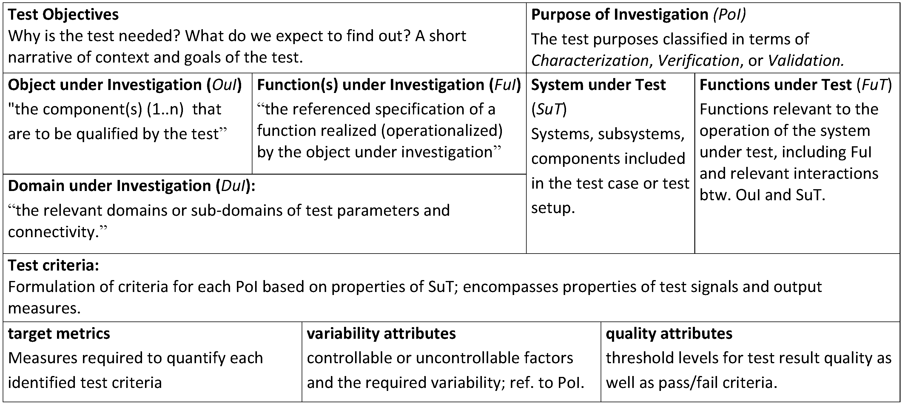
3.2.1. Formalising Test Objectives: From PoI to TCR, to Evaluation Metrics

The Test Case formulation includes several refinements on the Test Objectives: the Test Criteria (TCR), corresponding to the Key Performance Indicator (KPI) in a use case, serve as formalisation of the test objectives into a quantifiable metric. Often, metrics proposed early in the test development need to be revised.
Here, it helps to step back and look at the “test objectives” as a pure narrative formulation of the motivation and rationale of a test. In a second step, the test objectives are formally refined into the Purpose of Investigation (PoI) using a differentiation between
  • Verification
  • Validation
  • Characterisation
By itemising the test objectives, each addressing exactly one of the above three categories, the formulation of test metrics and procedure is greatly facilitated. The formalisation is likely to refine the test narrative so that the need for additional experiments or a dependency between experiments materialises.
Verification and Validation tests imply experiments where the outcome is judged by a pass/no-pass criterion. For Characterisation experiments, the objective is to model a specific performance or behaviour of the System under Test. Following a widely accepted distinction between validation and verification, we define:
  • Validation tests: Functional requirements and passing criteria are provided as abstract measures, where experiment results are subject to some expert interpretation to decide upon pass/no-pass.
    Implication for Test Case: Test criteria are formulated qualitatively; a qualitative passing criterion is required (consider who is the expert qualified to pass the judgement).
    Example: Is a controller ready for deployment in the field? Relevant experts here: development or field engineer.
  • Verification test: Tests where requirements are formulated as quantitative measures and thresholds of acceptable values are quantified.
    Implication for Test Case: Test Criteria are formal and quantified. A passing threshold is defined.
    Examples: (i) Standard conformance testing; and (ii) passing the set of tests (test harness) applied in software unit-testing.
  • Characterisation test: Here, a measure is given without specific requirements for passing the test. Implication for Test Case: Test Criteria are quantified, typically given key metrics or performance indicators. A passing threshold is not defined, but a metric for expected result quality can be provided (validity of experiment, not of OuI).
    Examples: Characterising performance of a system; characterising the physical parameters of a component for developing an equivalent simulation model.
Following the textual formulation of PoIs, the next step is a further formalisation of the Test Criteria (TCR), which take reference to domains and components identified in the System under Test, and would suitably be represented as mathematical formula.
The target metrics, variability attributes and quality attributes each identify parameters related to the SuT, to suitably measure, perturb and assess experiment result quality, respectively.

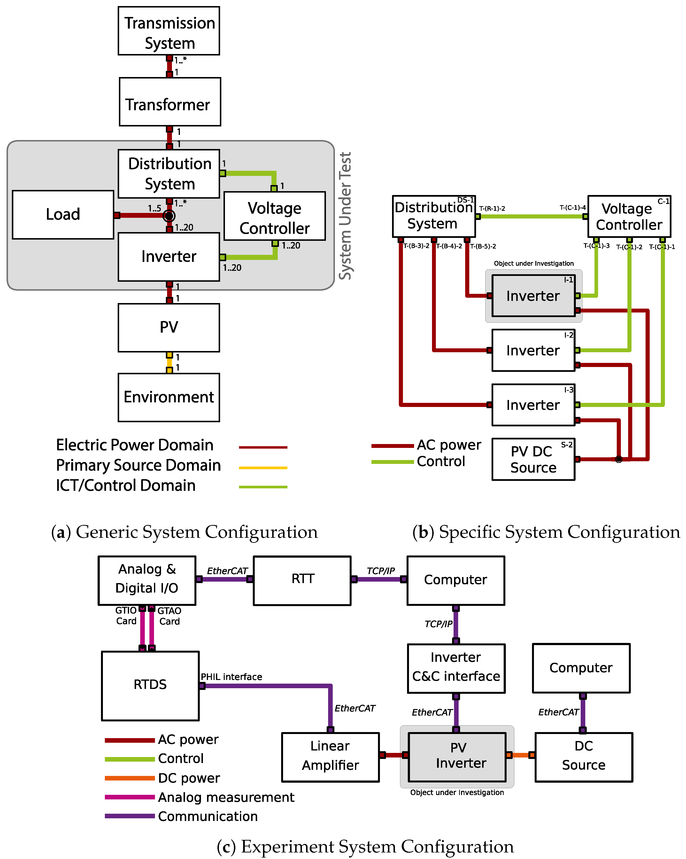
3.2.2. Configuration for Experiments: Abstract System Concept to Experiment Configuration

While a test case describes in the most generic terms the requirements and observables to be examined, these must eventually be mapped onto a specific laboratory infrastructure. Documenting this mapping is the task of the three levels of system configuration descriptions; a Generic System Configuration (including System under Test) in the Test Case, a Specific System Configuration (i.e., the Test System) in the Test Specification, and an Experimental System Configuration (i.e., Experiment Setup) in the Experiment Specification. Each configuration targets a certain level of abstraction, and fulfils a different role in their respective test description document. We proceed to list these configurations below, and indicate both their level of abstraction and their role in the overall description.
Generic System Configuration (GSC): The GSC is made to indicate the functional or abstract structural need of the System under Test (SuT). It represents the SuT at a high level of abstraction, but still allows identifying test criteria, domains, and key system functions. The GSC will thus typically define which component types (classes) form part of the SuT, what their parameters can be, and how these components may be connected, but not exactly how many of these components there are, or the exact topology of the system. Further, each component type may be defined at a high aggregation level, e.g., wind farm, or at a low level, e.g., battery cell, depending on the requirements of the test. In object-oriented programming, the GSC may be likened to defining the classes of components included in the test system.
Specific System Configuration (SSC): The SSC is made to specify the exact number of components forming the SuT, their topology and any additional requirements on parameters for the test. The SSC is specific because it names the key factors and observables, as well as the expected system topology, i.e., it represents an instance of the SuT identified. Justifiable reasons for leaving SSC parameters undefined relate to system parameters and properties that are non-critical for the test-criteria, as well as parameters that will vary strongly with the choice of testbeds. In the latter case, acceptable and preferred parameter ranges can be identified. The SSC will thus typically leave certain aspects of the SuT open for mapping by the specific testbed, and instead define requirements externally with respect to the SuT and/or specific aspects of the SuT required to fulfil the Test Objective. Further, as Test Cases may involve more than one Test Specification, the SSC serves to indicate which portions of the SuT are in focus for a particular Test Specification. For example, in test cases with focus on communication tests, the electrical grid topology would be left unspecified, or vice versa.
Experiment System Configuration (ESC): The ESC or Experiment Setup represents a realisation of one SSC mapped onto a specific testbed, and serves as a documentation of the physical and software realisation of the experimental setup as used during execution of the experiment. As the ESC serves to document the testbed configuration, the SuT is not in focus and only the OuI is transferred from SSC to ESC. Thus, an ESC will typically list both makes and models of equipment, specific parameters of this equipment, and their setting or operating mode during execution, but also the means of preserving recorded data or the equipment required to generate a certain test signal, simulators and simulation model version, the OuI version, or method of interfacing OuI with testbed and other interface components.
Table 1 provides an overview of the differences between the different SCs.
As an example of the three levels, Figure 5 shows system configurations from a test involving coordinated voltage control of remotely controllable Photovoltaic (PV) inverters.
In the GSC, Figure 5a, only coupling domains are specified, and the number of units involved is not specified. The test System (SSC) (Figure 5b) identifies the OuI as a single inverter, but requires both the coordinated voltage controller and several other inverters to be connected to a distribution system. Finally, in the experiment setup (ESC, Figure 5c), elements required to emulate signals for the OuI are specified, which, together with a specification sheet (not shown), serve as a complete documentation of the experimental setup. Only one PV inverter is seen in a PHIL setup, while the voltage controller is implemented on a computer, and the other inverters as well as the distribution grid are simulated on a digital real-time simulator.
By forming a chain through layers of abstraction, going from GSC to ESC allows tracing how the PoI is fulfilled at each layer, and serves to inform the choices, which must inevitably be made during the eventual mapping of the GSC onto a testbed. The following subsection discusses the mapping procedure in more detail, including how the choices made during a mapping can be both enforced and documented.

3.2.3. Experiment Realisation Plan

The experiment realisation plan should help HTD practitioners to transition from abstract test descriptions to actual experiment implementations, as also found in the test description guidelines [51]. This is achieved via two concepts: an RI database that provides information about accessible test labs, and a guideline that gives structured advice for the usage of the database for selecting appropriate RI(s) and mapping a given Test System to the RI(s).
The RI database has been set up as a part of the ERIGrid project [55] (A subset of the database has been released in HTML form as part of the ERIGrid RI descriptions at, for example: https://erigrid.eu/components-attributes-of-test-center-for-smart-grids-and-electromobility-iee/). It contains information on the available lab components and their connection possibilities for the different RI of the project partners. This information is structured by a specifically developed data model that is loosely based on the CIM standard, as described in [17,55]. Different ways of representing infrastructure between different RIs are mapped to this model at each specific location. In addition to the physical configuration of RIs, the data model facilitates descriptions of the control capabilities of individual RI equipment as well as an indication of the possibilities for deploying third party control solutions at a particular RI. In the context of smart grid research, a description of these control capabilities is essential for understanding which types of experiments can be accommodated at a particular site. These capabilities are described in accordance with the generic reference model for control hierarchies [16,56].
All data elements are designated as mandatory or optional in order to achieve a minimal baseline model across all RIs while allowing individual RIs to be modelled in greater detail. This way, a common understanding of RI capabilities is established across several institutions. Furthermore, the SQL-based implementation of the database opens up future possibilities of semi-automated processing of RI configurations, for example by searching for particular combinations of components or the ability of a laboratory grid to match the dimensional or topological requirements of a particular experiment. The web-based open access hosting of the database is a step on the way towards a pan-European testing and research platform that allows users to find the best RI for their particular application cases. However, some institutions wish to keep their RI layout information confidential. An alternative use of the RI database may therefore be given by adopting the concept within closed company networks to improve lab accessibility only in that consortium.
The experiment realisation plan is closely linked to the RI database and outlines multiple usage scenarios. It is therefore not to be understood as a strict set of rules for the use of the database, but rather as an illustration of the database capabilities. The guideline describes a two-stage process for deriving an experiment implementation from a given test specification. The first stage of the process can be called the assessment phase. Most practical tests do not require the experimental setup to follow the test specification in all aspects; certain aspects, e.g., grid topology, controllability, static and dynamic parameters will have a strong impact on the outcome of the test while others can be ignored. For example, the communication protocol and bandwidth of a PV inverter do not affect the outcome of an anti-islanding test. However, these would be of high relevance for an interoperability test of the same inverter, while the electrical characteristics of the inverter might be irrelevant. HTD practitioners are asked to assess the degree of precision to which the experimental setup needs to replicate various aspects of the test specification, by examining each aspect of the test system and assigning one of four different precision levels to it:
  • precise: The respective system aspect has to be matched 1:1 (e.g., exactly the same model of electric vehicle, the exact grid topology, the same communication protocol, etc.).
  • equivalent: The respective aspect has to be matched equivalently (e.g., an electrical vehicle with the same charger and battery size, a grid topology with the same number of nodes, a communication protocol with the same or a better fidelity, etc.).
  • nominal: The respective aspect can be matched with some deviations, but they should only lead to marginal influences on objective and results (e.g., a controllable load simulating an electrical vehicle, a grid connection providing similar load/voltage characteristics, some means of communication without regard for the specifications, etc.).
  • irrelevant: The respective system aspect does not influence the test objective and results.
A test system (SSC, cf. Section 3.2.2) aspect, on the other hand, may vary in scale. It can be a component, a set of components or even just a certain component or connection property. The required focus and level of detail of the aspect overview depends entirely on the given system and test case. Thus, a comprehensive list of potential aspects cannot be established in the context of this paper. The outcome of the assessment phase is a table that pairs each system aspect with a precision category. An example for a part of such an assessment table is given in Table 2. The table provides a valuable document for the practical interpretation of a test system. This is especially useful if the implementation of the experiments is not conducted by the same people who designed the TC and TS.
After the assessment table is established, it can be used to communicate the fixed implementation requirements of a test and to prioritise the rest of the system properties. These constraints, together with the prioritisation, enable an iterative search of the database. In a significant number of cases, user requirements and the RI capabilities will not be a perfect match; an iterative search will then help to identify the most suitable RI to implement an experiment in.
The first search pass identifies all RIs fulfilling the most crucial requirements. Subsequently, more constraints are applied until only one RI is left, including the set of suitable components it provides. This process will also alert the user if the planned experiment cannot be fully implemented in any available RI. In the latter case, either the TS has to be revised and/or precision requirements have to be relaxed, or the user may consider implementing the experiment as a multi-RI setup where components from several RIs are weakly coupled by real-time data exchange. Further guidelines on the use of the RI database [55] for experiment implementation can be found in [51].

3.2.4. Systematically Quantified Test Results: Design of Experiments and Qualification Strategy

The HTD terminology contains several concepts that possess a counterpart in DoE, as discussed in [50]. The mapping between these two conceptual views spans across the different stages of the HTD. For example, the identification of treatment factors (the factors of interest in a DoE-guided test) is to be documented in the form of variability attributes in the TC and as input parameters in the TS. This illustrates a major benefit of the HTD: it requires its users consider essential DoE concepts from the very beginning of the test planning and refine them over the course of the specification process. Accordingly, the DoE concept of a system response is to be specified in stages as test criteria and target metrics (TC stage) and output parameters as well as target measures (TS stage). Factors whose influence is not of interest (nuisance factors) are in the TC stage considered along with treatment factors as variability attributes while in the TS stage they can be separated and discussed in the context of other parameters and uncertainty sources. Finally, the design chosen for the exploration of a system’s factors can be specified, justified and refined in the context of the test design (TS stage) and the experimental design and justification (ES stage).
The aim of an experiment strongly determines how the DoE process is planned and results are interpreted. As described above, these aims are specified in the HTD as the PoI, falling into the categories characterisation, validation or verification. These PoI categories have different implications on the necessary DoE considerations. As an example, imagine a test system with intrinsic fluctuation. A common DoE-related technique for the interpretation of results in the presence of noise is given by Analysis of Variance (ANOVA, see, e.g., [57]). It allows its practitioners to explore (with a given significance level α ) whether the influence of a given factor is stable against the system’s fluctuation. In the·case of a characterisation experiment, users of ANOVA would generally explore which significance levels α can be reached.
In a validation experiment, on the other hand, users will want to interpret whether the calculated α value indicates a test that satisfies the given quality attributes. Finally, verification experiments should have a required level of risk or significance specified in the context of the quality attributes so that ANOVA practitioners can directly tell whether a test has passed or failed.
Another benefit the HTD provides for DoE practitioners is given by the formulation of a qualification strategy which allows recording thoughts about the dependency of planned tests and experiments [52], for example in such a case where a characterisation experiment precedes a validation experiment, to first characterise the communication latency of the testbed, and then validate the robustness of a control system to communication latency. To apply DoE techniques as efficiently as possible and minimise the risk of drawing false conclusions users are typically encouraged to make assumptions about the analysed system. As an example, the influence of some factors or factor combinations may be considered negligible so that they are ruled out from the experiment, or a linear behavior of the system dynamics may be assumed. Such assumptions have to be based on an understanding of the given system. Since an appropriate insight is not always given, especially in the case of highly interdisciplinary systems, employing screening experiments is a common practice in DoE (see, e.g., Chapter 5 of [58]). These types of experiments typically employ designs that are relatively cheap in the sense of requiring few experiment runs. As a consequence, they feature confounding of factors or factor combinations so that definite statements about factor influences cannot be made. Nevertheless, screening serves its purpose of providing its users with some initial insight into the tested system that can then be used for further experiment planning. In fact, some screening designs can be easily extended via so-called folding or reflected design to be turned into less confounded designs [59]. This way, the data gained from the screening can be reused in the actual experimentation.
The HTD qualification strategy provides a framework to document which experiments are used for screening and which for definite statements concerning the PoI. Different types of relationships between the various TS and ES can be considered. The process is flexible enough to express strong information dependencies [52]. As an example, some TS will be only roughly outlined in the beginning and receive refinement after several screening experiments have been successfully conducted and analysed.
This refinement concept of the HTD is another point that is often needed in DoE. To ensure a statistically correct DoE process, several control methods can be employed. For example, a correlation matrix for the chosen sampling strategy may be established to analyse whether factors may be confounded [59]. Similarly, other control methods can be used to check to quality of chosen regression or prediction models. If some of the made choices are discovered this way to be faulty, TS and ES should be refined or additional TS/ES established. Either way, HTD practitioners are encouraged to document the refinement process to make their reasoning more traceable by other researchers that may attempt to reproduce their results.
A increasingly common need in complex testbeds is the need to assess testbed performance as a factor of influence. For example, in remote experiments, the communication latency needs to be characterised to serve as factor in subsequent experiments [53,60].
This qualification strategy can be formulated as free text or in tabular form, but it can also be formalised further into a semantic meta-model of a complex test-design. A step-by-step guideline and examples are found under [51].

4. Application of Holistic Test Description

The HTD offers several benefits that facilitate the realisation of complex and repeatable experiments. In this section, we demonstrate and evidence benefits such as
  • reproducibility of experiments in different laboratories, as flexibility in the experiment realisation can be achieved;
  • self-contained sharing of test requirements across different test organisations, directly based on HTD documentation;
  • supports the scoping of simulation models as part of a test system;
  • traceability of the experimental procedures, enabling, for example, reproduction and round robin testing as a pre-cursor to developing standardised test procedures;
  • repository creation and streamlining of similar and repeated the test processes, retains domain expertise embedded in the repository;
  • creation of modular test specifications, which in turn enables re-use of test components, and supports test automation; and
  • plan and coordinate complex tests involving multiple experiments.
We illustrate and discuss a full HTD in context of a completed experiment in Section 4.1, introducing a specific application case to give an example of particular improvements that can be achieved via the HTD. Section 4.2, on the other hand, presents a general view on challenges that regularly arise in CPES testing, aggregated from various test cases; the benefits provided by the HTD can help to handle these challenges. Section 4.3 finally provides an overview of the types of test cases in different research projects that already have employed the HTD. This section aims to provide the reader with a concrete sense of how the HTD can be employed while at the same time getting a general idea of the application possibilities of the procedure.

4.1. Illustration Example

This section explains an example test case of how a PHIL based test was designed, implemented and executed for the verification of a Fast Frequency Response (FFR) control scheme. This example is then examined in conjunction with the HTD to identify advantages in adopting such test methodology in:
  • Enabling repeatability of the test using different HIL implementations: Characteristics of different HIL setups between involving a digital grid simulator and control system under test are examined, particularly to understand the impact on test repeatability.
  • Enabling the execution of the test in different research infrastructures using different test setups: Focus bise on how a unified approach to the test requirements specification facilitates independent, yet complementary experiments.

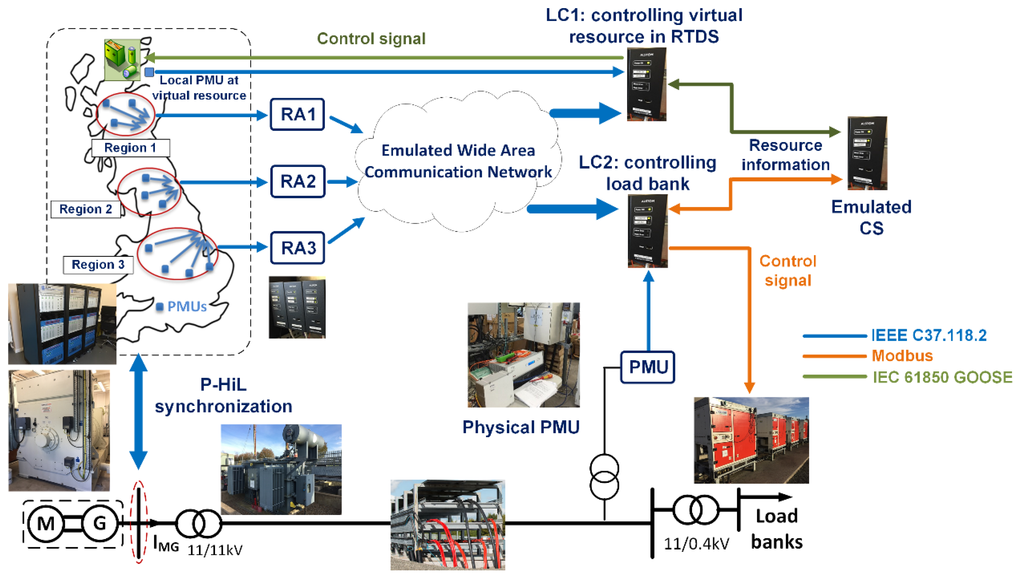
4.1.1. Enhanced Frequency Control Capability (EFCC) Performance Verification

The EFCC control scheme relies on wide-area synchrophasor measurements (streamed from Phasor Measurement Units, PMU) for the detection of grid frequency events and the subsequent timely and optimal deployment of energy resources (e.g., energy storage, generation, demand side response) to contain the grid frequency deviation, while avoiding angular instabilities that can be caused by an over response. This frequency control requirement is particularly important for low inertia grids. The scheme utilises Local Controllers (LCs) for the deployment of energy resources. LCs rely on Regional Aggregators (RAs) to provide an aggregation and signal qualification of PMU measurements from different locations in the grid. Frequency and Rate of Change of Frequency (RoCoF) are the main input signals to the control logic. A Central Supervisor (CS) is a component used to prioritise and arm local controllers based on resource availability, resource characteristics and grid inertia. The control scheme can also fall back to a local control mode, which relies solely on PMU measurements local to deployable energy resource in the case of loss of communications. This local control mode deploys resources according to pre-set response thresholds. Detailed information about the control scheme can be found in [61].
The main objectives of this test were twofold:
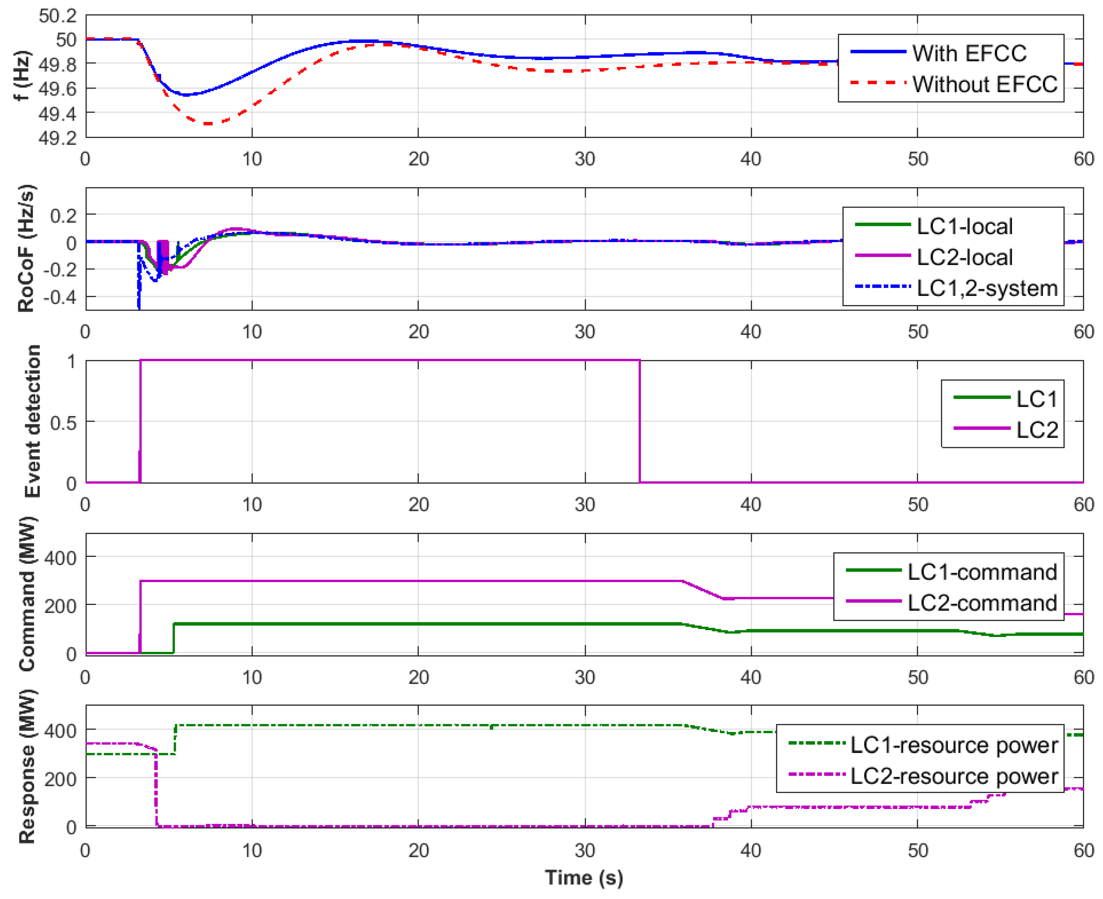
  • Verification that that the EFCC control scheme is capable of identifying grid frequency events correctly and deploying an appropriate amount of response to contain the frequency deviation: Verifying scheme sensitivity to frequency events and stability against non-frequency events (e.g., faults) are the focus here.
  • Quantification of the enhancement of frequency containment using the EFCC control (i.e., compared to relying solely on primary frequency response): Speed and extent of frequency containment are the focus here.
Moreover, it was critical that as many of the EFCC control scheme hardware components (LC, RA, CS, and PMU) as possible were tested in an independent physical test environment akin to a field deployment. Consequently, an integrated system test was a necessary follow up to manufacturer factory acceptance tests.
Figure 6 illustrates the realisation of the test in a PHIL setup. A PHIL setup was necessary to conduct the test for three main reasons. First, testing physical and communication interfaces between the EFCC control scheme components and deployable energy resources was a key requirement. Second, the effectiveness of the EFCC control scheme in containing the grid frequency after an event demanded a closed loop test setup. Third, evaluating real-time controller performance (including the impact of communication network performance) was key, which necessitated a combination of power hardware and real-time simulation.
If an informal method of describing the test objectives and requirements for the case described thus far wer adopted, it would become challenging to translate these into different test laboratories with comparable test outcomes. Moreover, further difficulties in experiment realisation can be faced if the test is to be conducted in a distributed fashion (e.g., across different laboratory infrastructures). The following examines how the HTD can be applied to the illustrative EFCC test case, drawing on the main points of the process detailed in Section 3.1. This treatment is split across the three main stages of developing a test case description, test specification and experiment specification.

4.1.2. EFCC Test Case Description

The focus in this stage of the HTD development is to define the scope of the system under test and test objectives, which will ultimately translate to a specific test design (corresponding to the test specification) and specific test implementation(s) (corresponding to the experiment specification). To develop the formal descriptions established by the HTD, we first refer back to the above narrative explaining the EFCC control scheme operation, motivation for using it and objectives of testing. The test case clearly requires a representation of a frequency response that is characteristic of a low inertia grid. As such, the system configuration considered for the test is that of a transmission grid with low inertia generation. In other words, the EFCC control scheme to be tested must be exposed to the electrical operational conditions of a low inertia grid, particularly during a frequency disturbance. In turn, the control action performed by the EFCC scheme will influence the grid frequency during an event by deploying controllable resources. The low inertia grid, EFCC control scheme and deployable resources form our system under test (SuT). Within the SuT, we need to define the individual or collective elements which are the focus of the test. To this end, an object under investigation (OuI) and function under investigation (FuI) are defined. In this example:
  • OuI: Although a wide-area control scheme is being tested, it is the LCs which deploy the energy resources during grid frequency disturbances that are the focus of the test.
  • FuI/FuT: Following on from the OuI definition, the LCs ability of determining and deploying the appropriate amount of energy resources in response to a detection of a grid frequency disturbance is the functionality that is being investigated. Note that other functions are present and operational during testing (e.g., the RA aggregation of PMU measurements). These are referred to as the functions under test (FuT), which are an essential part of the SuT, but are not the focus of the test (i.e., a direct verification of their performance is not performed).
This process continues to detail the quantifiable metrics of the FuI against which the test outcomes are assessed. In this example, the aforementioned objectives of the test imply that verification of system performance is of most interest. These objectives can be detailed in a set of distinct PoI that expose the SuT to specific test conditions through which the FuT performance can be evaluated. Example PoI in this case include:
  • Verify that the LC successfully detects grid frequency disturbances necessitating a response.
  • Verify that the LC remains stable against grid frequency disturbances not requiring a response (e.g., over-frequency resulting from a short circuit).
  • Verify that the LC deploys the expected amount of resource with reference to the severity of the disturbance.
For the sake of brevity, the PoIs corresponding to the response quantification (characterisation-type PoI, cf. Section 3.2.1) are omitted. When conducting the experiment associated with the various verification PoI, key experiment variability and quality factors are defined. For example, creating a frequency disturbance test condition is directly controllable via initiating a grid power imbalance, while the resulting RoCoF measured by the LC is not directly controllable. Pass and fail criteria in relation to the LC response are measured in terms of actual response versus expected response for a given level of frequency disturbance detected by the LC.

4.1.3. EFCC Test Specification

Following on from the test case description, a test design is specified along with several measurable parameters that are used to evaluate the test criteria. In our example case, verification of the performance of the LC is key and as such, the test design reflects the need to expose the LC to a comprehensive range of grid disturbances while measuring its response to each disturbance. Table 3 shows an excerpt from a test matrix designed to expose the LC to aforementioned grid disturbances; combinations of different generation loss levels, locations and available resource capacities are tested. A factorial or manual discrete approach to specifying these test parameters can be adopted to create this matrix.
To perform the verification of the LC performance, it is necessary to measure the following:
  • amount of grid frequency containment following a genuine grid frequency event; and
  • amount of resource deployed in relation to the event severity and LC settings.
Further, the test specification includes an understanding of their uncertainty and variability in these metrics, and the detailed test system (SSC), including the configuration of the electrical grid and communication network, which are to be partially simulated and partially emulated in a physical laboratory.

4.1.4. EFCC Experiment Specification

The test case description and test specification should hold regardless of which research infrastructure performs the test. However, the realisation of the test can be achieved in different ways (e.g., simulation only or HIL). Although it has been established earlier that this example test case requires a PHIL test, a Controller Hardware-in-the-Loop (CHIL) experiment was realised in the first instance, to de-risk the MW-scale PHIL setup, as the control system is pre-production and not well documented. The CHIL setup included the real-time digital simulator, LCs and RA, and aimed to determine the characteristics of the LC response under different control settings (screening, characterisation), while preserving the same test design and configuration as for the PHIL setup.
The PHIL experiment setup is illustrated in Figure 6. A real-time digital simulator was used to model the grid while physical controllers were deployed on a low voltage distribution network with load banks as the physical deployable resource. Physical controllers were also interfaced with energy storage system models in the real-time simulation. Figure 7 shows a sample of the measurements made during the execution of test ID 1.1, as summarised in Table 3. The observed response of the control scheme to the grid event can be used to evaluate the performance of the control scheme. Further information about the PHIL setup and tests conducted can be found in [61,62].

4.1.5. Reflection

One of the key factors that need to be considered when observing the outcomes of the test is the extent that the specific test setup implementation has on the observations. In this example case, the implementation of PHIL test environment and associated round trip delay between the physical infrastructure and simulation must be characterised prior to the test execution so that it is incorporated into the test uncertainty. Once this has been characterised, experiments can be transferable between different research infrastructures with different PHIL setups. This issue is not considered significant in the CHIL implementation for achieving the test objectives.
Finally, the formal abstractions associated with the OuI afford the ability to conduct the same test over multiple research infrastructures simultaneously while meeting the test objectives (more formally PoI). In this example case, a clear boundary can be established between the controllers under test and the power system (composed of both real-time simulation and physical test network). Moreover, this separation can be leveraged to investigate the behaviour of communication network performance (e.g., latency) on the performance of the controllers.
The illustrative example above underlines the need for a well-defined domain-specific approach to the testing of CPES, a requirement that is not addressed particularly well by standards as alluded to earlier in Section 2.3. By implementing the HTD in our particular example, the following key benefits are gained:
  • Semantic demarcation between the test objectives and the implementation of the experiment: so long as the test objectives (i.e., OuI) and the ensuing performance criteria to be evaluated are defined, flexibility in the experiment realisation can be achieved. Thus, reproducibility in different HIL setups is possible. This is evidenced by achieving the verification of controllers’ performance connected to physical resources as well as simulated resources. On a larger scale, interfaces in the experiment could span across multiple laboratories.
  • The HTD documentation is a practical means of sharing the test requirements across different test organisations or experiment implementations. By extension, traceability of the experimental procedure to the OuI is achieved, which would enable round-robin testing as a pre-cursor to developing standardised test procedures. As presented above, conducting a CHIL experiment paved the way to a more comprehensive PHIL verification for the control system.

4.2. Challenges Addressed and Application Experience

Since the HTD approach has first been described in 2016 [7], it has found numerous applications, both within ERIGrid and in unrelated projects. In this section, the specific challenges experienced in testing activities are summarised and the benefits of HTD application are articulated. CPES testing activities carried out within the ERIGrid project are the main source of these experiences.
Challenges associated with replication of tests:
  • Difficulty of interpreting component connectivity from experiment descriptions
  • Difficulty of replicating sequentially the target metrics and the variability attributes
Since different setups and workflows have hindered a common understanding and thus comparability of results, too often innovation trumps significance in the valuation of test outcomes. However, reproducible significant results are essential for regulation, harmonisation and standardisation, which are key economic factors for industrial development of CPES. Replication in another laboratory is the only empirical way to evidence significance of results.
The HTD supports the endeavour of replication via clear separation of test descriptions into the different stages, each with a corresponding template for documentation. Researchers from different domains and different institutions can first draft a common understanding of a test system with the TS. Then, for each laboratory, a distinct ES interpretation can be established. Comparison between the involved parties and with reference TC/TS would help to avoid misunderstandings and establish a mapping between the experiment results. Similar application cases are being employed in the ERIGrid project and the test descriptions and the experiment results are presented in one of the forthcoming project reports.
Challenges associated with multi-domain test cases:
  • Shared understanding of test purpose across domains (e.g., what level of detail is relevant from one domain to cause a relevant influence in another domain)
  • Lack of clarity on the domain boundaries
  • Lack of comprehensive recording of the domain specific target metrics (e.g., measuring voltage level but not the communication delay during the execution of control system)
Considering multiple domains in a single test system, the most common domains are the ICT and the electrical domains. The electrical and ICT domains aspects are difficult to align, as professionals from different domains miss the shared overview and coupling points within the entire test system. Without a structured test description, this leads to unnecessarily long preparation time and potentially incompatible models. Multi-domain testing activities in ERIGrid which that have been susceptible to the aforementioned challenge occurred for example where the testbed is a co-simulation. One of the tests described in [64] deals with the impact of ICT-related aspects in a low voltage distribution grid, where meters send information about local voltage levels via a communication network to a remote controller actuating the tap position of an OLTC transformer. In this simple study case, ICT-related aspects of interest were communication delays, which interacted with controller dead-timeouts, causing a non-deterministic voltage control performance. Here, the identification and selection of critical study parameters required a joint and structured view of the test objectives as well as of the testbed configuration.
Challenges for experiments in (co-)simulation testbeds:
  • Simulation models are abstract in nature, but abstraction levels vary
  • Identification of suitable model-components for a co-simulation setup
  • Re-use of simulation components/models
A critical aspect of pure simulation setups lies in the fact that simulation models exist on a higher abstraction level than hardware components and thus may display more heterogeneous characteristics. In other words, it can be more difficult for software than for hardware experiments to identify the most suitable components since the available models display different levels of aggregation of CPES subsystems.
With the documentation of system configurations at requirements level (test system and SSC), the HTD offers a framework for scoping types of components, data flows and parameters required for a given test. This way, experts may identify the most suitable simulation models for their experiments, considering model structure and functionality rather than implementation technology. By documenting selected testbed configurations (ESC), later re-use is facilitated. Filled in HTD templates for such kind of tests are included in [64].
Challenges associated with multi-stage and multi-site experiments:
  • Proper description and inclusion of all the relevant components to be characterised and validated
  • Tracking changes that occur between multiple interdependent experiments
  • Misunderstandings between expert groups from different locations
  • Lack of full understanding of results in earlier stages with their related uncertainities
Multi-stage and multi-site experiments involve the breaking-down of a large test objective and test system into well defined stages where each stage uses the specific capabilities of the dedicated test site. As CPES tests are often expensive to implement, such tests need to be planned clearly and in a coordinated manner. Incomplete consideration of components to be characterised may lead to second and third round tests to record missing results. Early-on clarification of the Object(s) under Investigation will lead to clearer definitions of the domains they belong to and the target metrics to be addressed. From the testing experiences which used HTD, one can observe that thoughtful early listing of the components and functions that form the complete system under test leads to reduced changes and earlier arrival at the final test plan.
Challenges associated with real-time multi-site experiments:
  • Incompatibility of resolution and type of measurement data and control signals
  • Black-box test setup on the other end without mutual test description procedure
  • Lack of full understanding on how and where the measurements from a real-time experiment in the other RI is conducted
Experiments involving several testbeds or a virtually connected testbed, especially if located in geographically distant research infrastructures, allow re-use of complex, expensive, immobile, or unique equipment (cf. Section 2.4). Researchers and testbed engineers gain clarity by separating challenges with the testbed from the test objectives and system under test. An example of a real-time and multisite experiment is the test case implemented within the ERIGrid project [60], which involved asynchronously interconnected geographically distributed simulators, using equipment and experts situated in Germany and Greece. The HTD was used to describe the test in such a way that two test specifications and their associated experiment specifications are described under single test case. A qualification strategy included assessment of the communication latency and sensitivity prior to the targeted control system experiments [60].

4.3. Collected Application Evidence

The HTD process and templates have been used within the ERIGrid project for the structuring and documentation of over 15 application cases (for details, see also [51]). Some detailed cases have been linked to the research work conducted by project partners and the vast majority of HTD applications are linked to Transnational Access (https://erigrid.eu/transnational-access/selected-projects/) activities, which have been conducted by researchers from outside the project consortium. The HTD method has also been applied in other projects than ERIGrid.
The EU H2020 SmILES project [65] is one where four cases of HTD application are observed. The SmILES project has adopted the ERIGrid HTD method and incorporated it into the project’s own method, identifying extension areas to the HTD method for creating domain- and tool-independent reproducible simulation models. Specific extensions include templates for controller description, component models, optimisation objectives and constraints, and a common data format [54].
Taken together, the extended method makes precise documentation of simulations possible by explicitly separating the why, what and how of each simulation. This allows accurate transfer of simulations even between partners operating at disparate scales, e.g., seconds and hours, using orthogonal means of simulation, e.g., direct integration and optimisation, or working in different application domains, e.g., electrical batteries and district heating networks. In the context of the SmILES project, the extended method is demonstrated to allow transfer of several simulations between partner toolchains, despite major differences in modeling approach.
The EU FP7 project ELECTRA IRP [66] is another project where the HTD method has been employed to describe several test cases for testing the web-of-cells real-time control concept of future power systems. In addition, in the H2020 SmartNet [67] project, the aforementioned approach has been successfully used to prepare the lab-based testing of the coordination schemes between transmission and distribution system operators [68]. The corresponding examples can be found in the open ERIGrid examples repository at [51].
More than half of the registered application cases have employed all available HTD templates, structuring their tests into test cases, test specifications, and experiment specifications. Of the remaining application cases, the majority has still implemented TC and TS descriptions while some have only provided TC descriptions. These different levels of HTD completeness are typically linked to different complexities in the application cases. It appears that the trade-off between detailing work and HTD benefits does not always justify completing all templates. The TC provides a general understanding of the objectives and scope of a test. The information is given in a standard format that makes it easy to compare TC content. The TS adds the benefit of splitting up complex TCs into manageable units. The ES, finally, documents the experiment implementation in a given RI and thus allows comparability between implementations, given the reproduction of experiment setups or employment of different laboratory infrastructures.
The vast majority of registered HTD application cases feature HIL-based experiments. Other cases have involved the explicit consideration of communication infrastructures or the remote coupling of laboratory infrastructures. This illustrates the usability of the HTD procedure for complex tests that involve the analysis of cyber-physical interactions and/or require coupling of remote or heterogeneous components in the experiment implementation.
A variety of application areas have been covered by the registered application cases. About half of the cases are focused on testing control and management solutions for microgrids or active distribution grids. This once more illustrates the applicability of the HTD to document test cases that involve the validation of complex management strategies involving the interaction of various components. Other areas that have been covered by application cases are testing of demand response solutions and control units for renewable energy sources such as wind power plants, multi-energy systems, and alternate power system control architectures.
Overall, experience from the ERIGrid project shows that the HTD procedure is applicable to a variety of testing technologies and systems under test. It can provide different benefits depending on the number of employed templates, but for the majority of the (complex) test cases it proved to be useful to document all stages of testing. However, the HTD methodology a flexible open tool that can be used or modified according to the needs of the experiments to trace the path between the abstract idea to the real test execution and reporting. The parallel test of the HTD was done in the ELECTRA IRP project to document the experiments, both in simulation and at a lab scale in a harmonised manner (for details, see [51]). It was intended to help in the refinement of the HTD methodology design by providing feedback though a preliminary use in a wide variety of test cases, evolving from the simulation experiments to the pure hardware tests.
For its use in ELECTRA IRP, an additional element was added to the HTD for reporting each of the experiment accomplished. The Experiment Reporting was also based on a template. The information in the Experiment Reporting template was intended to assess the validation of the Test Criteria corresponding to the Experiment Specification. It was also planned for extracting the main conclusions from the testing concerning the results, lessons learnt and open issues. The Experiment Reporting Template can be seen in Figure 8.

5. Conclusions

The presented HTD method offers overall control and traceability of the experiments with CPES. A test design specified using HTD templates allows planning and following up on complex CPES experiments, also by users not physically present in the laboratory premises. This saves time for the overall validation work, even if the preparation and writing of the test cases and corresponding test and experiment specifications may take some time (depending on the validation complexity of an experiment, this can vary from minutes up to several hours) but, at the end, the more detailed understanding of the testing goals, requirements, boundary conditions, etc. improves the whole process. As the detail of test descriptions can be adjusted, the overhead of following the HTD method in detail can be tuned to the needs of experiments. We recommend using the simplest variant in the preparation of any multi-disciplinary testing effort.
The HTD defines a technical language which one needs to know and understand to plan and execute experiments using the HTD framework. Precise and accurate descriptions of the HTD terminology are available within the templates, which facilitate common understanding. The method aligns well with state-of-the-art testing technology, including virtual and remotely coupled experimental platforms. The HTD templates and guidelines are now publicly available at [51]. The templates have been treated as a living document during the ERIGrid project phase, and they may be updated further in the future. The authors welcome feedback about missing key description parameters, and the users are free to develop and release customised versions of the templates.
A word of advice for future HTD users: As in any multi-disciplinary work, different understanding of terms in the HTD templates is likely. Typically, similar terms can be understood differently between power system engineers and computer science professionals. Hence, cross-checking the interpretation of key terms will always be needed to establish common understanding, especially in multi-disciplinary teams. This said, there are areas for future improvement which already have been identified:
  • The HTD concepts are in part new and not fully in line with common usage; for example, “system under test”, “function under test/investigation”, and “object under investigation” all relate to the often used terms “system under test” (ETSI-TDL), “Device under Test” (frequently used in hardware testing), “Hardware under Test” (used in HIL context), etc. This creates communication challenges, which may be alleviated by improved training materials.
  • Lack of guiding questions: Essentially, it is difficult to fill out the template ad-hoc, only based on the abstract HTD concepts, and not all fields are equally relevant. For example, the “precision of equipment or uncertainty measurement” may not always be part of the experiment planning. Additional guidelines may facilitate the learning process further, and establishing a community of experienced HTD users for knowledge sharing may be practical.
  • An HTD-planned experiment may never have been carried out as documented in the templates: as plans change, experiment designs get updated along the way. While this situation cannot be changed, the HTD documentation process may be improved by a systematic versioning or referencing system to facilitate revealing the final experiments.
  • Lack of tool integration: The system configuration annotation suffers from being a graphical dead-end. Tooling integration, e.g., between test system SSC and result evaluation, would also encourage detailing and updating test system and experiment descriptions.
When an experiment, planned using HTD, with minimal cost and in accordance with validation goals is successful, we realise concrete value: projects on target and budget, delivering tangible outcomes, have financial, intellectual and technical value.
The future work will focus on the application of the proposed methodology in other projects as well as the refinement of it based on the gained experiences. In addition, software tools supporting the whole process as well as for creating the different templates are potential future action items.

Author Contributions

K.H., introduction, background, guidelines overview and TCR, revision of complete manuscript, and conclusions; C.S., concept and DoE (BG and guidelines); I.F.A., conception, example, and review guidelines; V.H.N., background; M.Z.D., applications and evidence; J.M., applications and evidence; T.V.J., guideline SUT; H.G., example; O.G., guideline mapping and database description; D.E.M.B., guideline DoE; D.B., review and feedback; F.P.A., application feedback; and T.I.S., motivation, conclusions, review, and final editing.

Funding

This work received funding in the European Community’s Horizon 2020 Program (H2020/2014–2020) under project “ERIGrid” (Grant Agreement No. 654113).

Conflicts of Interest

The authors declare no conflict of interest.

References

  1. Colak, I.; Fulli, G.; Sagiroglu, S.; Yesilbudak, M.; Covrig, C.F. Smart grid projects in Europe: Current status, maturity and future scenarios. Appl. Energy 2015, 152, 58–70. [Google Scholar] [CrossRef]
  2. Mankins, J.C. Technology readiness assessments: A retrospective. Acta Astronaut. 2009, 65, 1216–1223. [Google Scholar] [CrossRef]
  3. Strasser, T.; Pröstl Andrén, F.; Lauss, G.; Bründlinger, R.; Brunner, H.; Moyo, C.; Seitl, C.; Rohjans, S.; Lehnhoff, S.; Palensky, P.; et al. Towards holistic power distribution system validation and testing—An overview and discussion of different possibilities. E I Elektrotechnik Inf. 2017, 134, 71–77. [Google Scholar] [CrossRef]
  4. Brundlinger, R.; Strasser, T.; Lauss, G.; Hoke, A.; Chakraborty, S.; Martin, G.; Kroposki, B.; Johnson, J.; de Jong, E. Lab tests: Verifying that smart grid power converters are truly smart. IEEE Power Energy Mag. 2015, 13, 30–42. [Google Scholar] [CrossRef]
  5. Steinbrink, C.; Lehnhoff, S.; Rohjans, S.; Strasser, T.I.; Widl, E.; Moyo, C.; Lauss, G.; Lehfuss, F.; Faschang, M.; Palensky, P.; et al. Simulation-based validation of smart grids–status quo and future research trends. In Proceedings of the International Conference on Industrial Applications of Holonic and Multi-Agent Systems, Lyon, France, 28–30 August 2017; pp. 171–185. [Google Scholar]
  6. Van der Meer, A.A.; Palensky, P.; Heussen, K.; Bondy, D.E.M.; Gehrke, O.; Steinbrink, C.; Blank, M.; Lehnhoff, S.; Widl, E.; Moyo, C.; et al. Cyber-physical energy systems modeling, test specification, and co-simulation based testing. In Proceedings of the 2017 Workshop on Modeling and Simulation of Cyber-Physical Energy Systems (MSCPES), Pittsburgh, PA, USA, 21–21 April 2017; pp. 1–9. [Google Scholar] [CrossRef]
  7. Blank, M.; Lehnhoff, S.; Heussen, K.; Bondy, D.E.M.; Moyo, C.; Strasser, T. Towards a foundation for holistic power system validation and testing. In Proceedings of the 2016 IEEE 21st International Conference on Emerging Technologies and Factory Automation (ETFA), Berlin, Germany, 6–9 September 2016; pp. 1–4. [Google Scholar] [CrossRef]
  8. IEC 62559-2: Use Case Methodology—Part 2: Definition of the Templates for Use Cases, Actor List and Requirements List; Technical Report; International Electrotechnical Commision: Geneva, Switzerland, 2015.
  9. Gottschalk, M.; Uslar, M.; Delfs, C. The Use Case and Smart Grid Architecture Model Approach: The IEC 62559-2 Use Case Template and the SGAM Applied in Various Domains; Springer: Cham, Switzerland, 2017. [Google Scholar]
  10. Uslar, M.; Rohjans, S.; Neureiter, C.; Pröstl Andrén, F.; Velasquez, J.; Steinbrink, C.; Efthymiou, V.; Migliavacca, G.; Horsmanheimo, S.; Brunner, H.; et al. Applying the Smart Grid Architecture Model for Designing and Validating System-of-Systems in the Power and Energy Domain: A European Perspective. Energies 2019, 12, 258. [Google Scholar] [CrossRef]
  11. Kaplan, D. Distributed Energy Resources Manager. U.S. Patent 12/905,292, 21 April 2011. [Google Scholar]
  12. Wang, J.; Chen, C.; Lu, X. Guidelines for Implementing Advanced Distribution Management Systems-Requirements for DMS Integration with DERMS and Microgrids; Technical Report; Argonne National Lab.(ANL): Argonne, IL, USA, 2015. [Google Scholar]
  13. Vogel, S.; Stevic, M.; Kadavil, R.; Mohanpurkar, M.; Koralewicz, P.; Gevorgian, V.; Hovsapian, R.; Monti, A. Distributed Real-Time Simulation and its Applications to Wind Energy Research. In Proceedings of the 2018 IEEE International Conference on Probabilistic Methods Applied to Power Systems (PMAPS), Boise, ID, USA, 24–28 June 2018; pp. 1–6. [Google Scholar] [CrossRef]
  14. Palmintier, B.; Lundstrom, B.; Chakraborty, S.; Williams, T.; Schneider, K.; Chassin, D. A Power Hardware-in-the-Loop Platform With Remote Distribution Circuit Cosimulation. IEEE Trans. Ind. Electron. 2015, 62, 2236–2245. [Google Scholar] [CrossRef]
  15. Ulrich, A.; Jell, S.; Votintseva, A.; Kull, A. The ETSI Test Description Language TDL and its application. In Proceedings of the 2014 2nd International Conference on Model-Driven Engineering and Software Development (MODELSWARD), Lisbon, Portugal, 7–9 January 2014; pp. 601–608. [Google Scholar]
  16. Strasser, T.I.; Moyo, C.; Bründlinger, R.; Lehnhoff, S.; Blank, M.; Palensky, P.; van der Meer, A.A.; Heussen, K.; Gehrke, O.; Rodriguez, J.E.; et al. An integrated research infrastructure for validating cyber-physical energy systems. In Proceedings of the International Conference on Industrial Applications of Holonic and Multi-Agent Systems, Lyon, France, 28–30 August 2017; pp. 157–170. [Google Scholar]
  17. Heussen, K.; Bondy, D.; Nguyen, V.; Blank, M.; Klingenberg, T.; Kulmala, A.; Abdulhadi, I.; Pala, D.; Rossi, M.; Carlini, C.; et al. D-NA5.1 Smart Grid Configuration Validation Scenario Description Method; Project Deliverable, H2020 ERIGrid (GA No 654113). 2017. Available online: https://cordis.europa.eu/project/rcn/198653/results/en (accessed on 13 June 2019).
  18. Papaioannou, I.; Kotsakis, E.; Masera, M. Smart Grid Interoperability Testing Methodology: A Unified Approach Towards a European Framework for Developing Interoperability Testing Specifications. In Proceedings of the EAI International Conference on Smart Cities Interoperability and Standardization, Helsinki, Finland, 29 November 2017. [Google Scholar]
  19. European Telecommunications Standards Institute. Methods for Testing and Specification (MTS); TPLan: A Notation for Expressing Test Purposes; Technical Report, ETSI ES 202 553 V1.2.1; ESTI: Sophia-Antipolis, France, 2009. [Google Scholar]
  20. European Telecommunications Standards Institute. ETSI Test Description Language; Technical Report. 2018. Available online: https://tdl.etsi.org (accessed on 13 June 2019).
  21. Centre for Testing and Interoperability. TTCN-3 Tutorial; Technical Report; ESTI: Sophia-Antipolis, France, 2013. [Google Scholar]
  22. Forsberg, K.; Mooz, H. System Engineering for Faster, Cheaper, Better. In INCOSE International Symposium; Wiley Online Library: Brighton, UK, 1999; Volume 9, pp. 924–932. [Google Scholar]
  23. International Electrotechnical Commission. Application Integration at Electric Utilities—System Interfaces for Distribution Management—Part 11: Common Information Model (CIM) Extensions for Distribution; Technical Report, TC 57—Power System Management and Associated Information Exchange; International Electrotechnical Commission: Geneva, Switzerland, 2013. [Google Scholar]
  24. International Electrotechnical Commission. Energy Management System Application Program Interface (EMS-API)—Part 301: Common Information Model (CIM) Base; Technical Report, TC 57—Power System Management and Associated Information Exchange; International Electrotechnical Commission: Geneva, Switzerland, 2014. [Google Scholar]
  25. International Electrotechnical Commissione. OPC Unified Architecture—Part 1: Overview and Concepts; Technical Report, TC 65/SC 65E-TR 62541-1:2010; International Electrotechnical Commission: Geneva, Switzerland, 2010. [Google Scholar]
  26. International Electrotechnical Commission. IEC61850—Power Utility Automation; Technical Report, TC 57—Power System Management and Associated Information Exchange; International Electrotechnical Commission: Geneva, Switzerland, 2003. [Google Scholar]
  27. CEN-CENELEC-ETSI Smart Grid Coordination Group. Methodologies to Facilitate Smart Grid System Interoperability through Standardization, System Design and Testing; Technical Report; CEN-CENELEC-ETSI: Brussels, Belgium, 2014. [Google Scholar]
  28. Schieferdecker, I. Test automation with ttcn-3-state of the art and a future perspective. In Proceedings of the IFIP International Conference on Testing Software and Systems, Natal, Brazil, 8–10 November 2010; pp. 1–14. [Google Scholar]
  29. Zeiss, B.; Kovacs, A.; Pakulin, N.; Stanca-Kaposta, B. A conformance test suite for TTCN-3 tools. Int. J. Softw. Tools Technol. Transf. 2014, 16, 285–294. [Google Scholar] [CrossRef]
  30. Broy, M.; Jonsson, B.; Katoen, J.P.; Leucker, M.; Pretschner, A. Model-based testing of reactive systems. In Volume 3472 of Springer LNCS; Springer: Berlin/Heidelberg, Germany, 2005. [Google Scholar]
  31. Palensky, P.; van der Meer, A.A.; López, C.D.; Jozeph, A.; Pan, K. Co-Simulation of Intelligent Power Systems—Fundamentals, software architecture, numerics, and coupling. IEEE Ind. Electron. Mag. 2017, 11, 34–50. [Google Scholar] [CrossRef]
  32. Nguyen, V.H.; Besanger, Y.; Tran, Q.T.; Nguyen, T.L. On Conceptual Structuration and Coupling Methods of Co-Simulation Frameworks in Cyber-Physical Energy System Validation. Energies 2017, 10, 1977. [Google Scholar] [CrossRef]
  33. Faruque, M.O.; Sloderbeck, M.; Steurer, M.; Dinavahi, V. Thermo-electric co-simulation on geographically distributed real-time simulators. In Proceedings of the 2009 IEEE Power Energy Society General Meeting, Calgary, AB, Canada, 26–30 July 2009; pp. 1–7. [Google Scholar]
  34. Guillaud, X.; Faruque, M.O.; Teninge, A.; Hariri, A.H.; Vanfretti, L.; Paolone, M.; Dinavahi, V.; Mitra, P.; Lauss, G.; Dufour, C.; et al. Applications of Real-Time Simulation Technologies in Power and Energy Systems. IEEE Power Energy Technol. Syst. J. 2015, 2, 103–115. [Google Scholar] [CrossRef]
  35. Lauss, G.; Faruque, M.O.; Schoder, K.; Dufour, C.; Viehweider, A.; Langston, J. Characteristics and Design of Power Hardware-in-the-Loop Simulations for Electrical Power Systems. IEEE Trans. Ind. Electron. 2016, 63, 406–417. [Google Scholar] [CrossRef]
  36. Nguyen, V.H.; Besanger, Y.; Tran, Q.T.; Nguyen, T.L.; Boudinet, C.; Brandl, R.; Strasser, T. Using Power-Hardware-in-the-loop Experiments together with Co-simulation in a holistic approach for cyber physical energy system validation. In Proceedings of the 2017 IEEE PES Innovative Smart Grid Technologies Conference Europe (ISGT-Europe), Torino, Italy, 26–29 September 2017. [Google Scholar]
  37. Lehfuss, F.; Lauss, G.; Seitl, C.; Leimgruber, F.; Nohrer, M.; Strasser, T.I. Coupling of Real-Time and Co-Simulation for the Evaluation of the Large Scale Integration of Electric Vehicles into Intelligent Power Systems. In Proceedings of the 2017 IEEE Vehicle Power and Propulsion Conference (VPPC), Belfort, France, 11–14 December 2017. [Google Scholar]
  38. Stevic, M.; Estebsari, A.; Vogel, S.; Pons, E.; Bompard, E.; Masera, M.; Monti, A. Multi-site European framework for real-time co-simulation of power systems. IET Gener. Transm. Distrib. 2017, 11, 4126–4135. [Google Scholar] [CrossRef]
  39. Lundstrom, B.; Chakraborty, S.; Lauss, G.; Bründlinger, R.; Conklin, R. Evaluation of system-integrated smart grid devices using software- and hardware-in-the-loop. In Proceedings of the 2016 IEEE Power Energy Society Innovative Smart Grid Technologies Conference (ISGT), Minneapolis, MN, USA, 6–9 September 2016; pp. 1–5. [Google Scholar]
  40. Marten, F.; Mand, A.; Bernard, A.; Mielsch, B.; Vogt, M. Result processing approaches for large smart grid co-simulations. Comput. Sci. Res. Dev. 2017, 33, 1–7. [Google Scholar] [CrossRef]
  41. Vellaithurai, C.B.; Biswas, S.S.; Liu, R.; Srivastava, A. Real Time Modeling and Simulation of Cyber-Power System. In Cyber Physical Systems Approach to Smart Electric Power Grid; Khaitan, S.K., McCalley, J.D., Liu, C.C., Eds.; Springer: Berlin/Heidelberg, Germany, 2015; pp. 43–74. [Google Scholar]
  42. Liu, R.; Vellaithurai, C.; Biswas, S.S.; Gamage, T.T.; Srivastava, A.K. Analyzing the Cyber-Physical Impact of Cyber Events on the Power Grid. IEEE Trans. Smart Grid 2015, 6, 2444–2453. [Google Scholar] [CrossRef]
  43. Franchioni, G.; Heckmann, W.; Brundlinger, R.; Numminen, S.; Mayr, C.; Martin, N.; Strasser, T. Final Report Summary; Project Report, FP7 DERri (GA No 228449). 2014. Available online: https://cordis.europa.eu/project/rcn/91201/reporting/en (accessed on 13 June 2019).
  44. Nguyen, V.H.; Tran, Q.T.; Besanger, Y. SCADA as a service approach for interoperability of micro-grid platforms. Sustain. Energy Grids Netw. 2016, 8, 26–36. [Google Scholar] [CrossRef] [Green Version]
  45. Fisher, R.A. Design of experiments. Br. Med. J. 1936, 1, 554. [Google Scholar] [CrossRef]
  46. Robbins, H. Some aspects of the sequential design of experiments. In Herbert Robbins Selected Papers; Springer: Cham, Switzerland, 1985; pp. 169–177. [Google Scholar]
  47. Taguchi, G.; Yokoyama, Y.; Wu, Y. Taguchi Methods: Design of Experiments; American Supplier Institute: Cairo, Egypt, 1993; Volume 4. [Google Scholar]
  48. Kleijnen, J.P. Design and analysis of simulation experiments. In Proceedings of the International Workshop on Simulation, Vienna, Austria, 21–25 September 2015; pp. 3–22. [Google Scholar]
  49. Giunta, A.; Wojtkiewicz, S.; Eldred, M. Overview of modern design of experiments methods for computational simulations. In Proceedings of the 41st Aerospace Sciences Meeting and Exhibit, Reno, NV, USA, 6–9 January 2003; p. 649. [Google Scholar]
  50. Van der Meer, A.A.; Steinbrink, C.; Heussen, K.; Bondy, D.E.M.; Degefa, M.Z.; Andrén, F.P.; Strasser, T.I.; Lehnhoff, S.; Palensky, P. Design of experiments aided holistic testing of cyber-physical energy systems. In Proceedings of the 2018 Workshop on Modeling and Simulation of Cyber-Physical Energy Systems (MSCPES), Porto, Portugal, 10–10 April 2018; pp. 1–7. [Google Scholar]
  51. Holistic Test Description Templates, ERIGrid. 2019. Available online: https://github.com/ERIGrid/Holistic-Test-Description (accessed on 13 June 2019).
  52. Pellegrino, L.; Arnold, G.; Brandl, R.; Nguyen, V.H.; Bourry, F.; Tran, Q.T.; Sansano, E.; Rikos, E.; Heussen, K.; Merino, J.; et al. D-JRA3.3 Improved Lab-Based System Integration Testing Methods; Project Deliverable, H2020 ERIGrid (GA No 654113). 2018. Available online: https://cordis.europa.eu/project/rcn/198653/results/en (accessed on 13 June 2019).
  53. Nguyen, V.H.; Bourry, F.; Tran, Q.T.; Brandl, R.; Sansano, E.; Rikos, E.; Heussen, K.; Merino, J.; Riaño, S.; Kotsampopoulos, P. D-JRA3.2 Extended Real-Time Simulation and Hardware-in-the-Loop Possibilities; Project Deliverable, H2020 ERIGrid (GA No 654113). 2018. Available online: https://cordis.europa.eu/project/rcn/198653/results/en (accessed on 13 June 2019).
  54. Gehrke, O.; Jensen, T. Definition of a Common Data Format; SmILES Deliverable Report EU Project No.: 730936; Technical University of Denmark: Lyngby, Denmark, 2018. [Google Scholar]
  55. Kulmala, A.; Mäki, K.; Rinne, E.; Gehrke, O.; Heussen, K.; Bondy, D.; Verga, M.; Sandroni, C.; Pala, D.; Nguyen, V.; et al. D-NA5.2 Partner Profiles; Project Deliverable, H2020 ERIGrid (GA No 654113). 2017. Available online: https://cordis.europa.eu/project/rcn/198653/results/en (accessed on 13 June 2019).
  56. Gehrke, O.; Heussen, K.; Merino, J.; Nguyen, V.; Kulmala, A.; Pala, D.; Rikos, E.; Bhandia, R.; van der Meer, A.; Brandl, R.; et al. D-JRA3.1 Improved Hardware and Software Interfaces; Project Deliverable, H2020 ERIGrid (GA No 654113). 2017. Available online: https://cordis.europa.eu/project/rcn/198653/results/en (accessed on 13 June 2019).
  57. Tabachnick, B.G.; Fidell, L.S. Experimental Designs Using ANOVA; Thomson/Brooks/Cole: San Francisco, CA, USA, 2007. [Google Scholar]
  58. Antony, J. Design of Experiments for Engineers and Scientists; Butterworth-Heinemann: Oxford, UK, 2003. [Google Scholar]
  59. Stamatis, D. Six Sigma and Beyond: Design of Experiments; Volume V, Six Sigma and Beyond. Vol. 5, Design of Experiments; St. Lucie Press: Boca Raton, FL, USA, 2002; p. 23. [Google Scholar]
  60. Montoya, J.; Brandl, R.; Vogt, M.; Marten, F.; Maniatopoulos, M.; Fabian, A. Asynchronous Integration of a Real-Time Simulator to a Geographically Distributed Controller Through a Co-Simulation Environment. In Proceedings of the IECON 2018—44th Annual Conference of the IEEE Industrial Electronics Society, Washington, DC, USA, 21–23 October 2018; pp. 4013–4018. [Google Scholar]
  61. Hong, Q.; Nedd, M.; Norris, S.; Abdulhadi, I.; Karimi, M.; Terzija, V.; Marshall, B.; Bell, K.; Booth, C. Fast frequency response for effective frequency control in power systems with low inertia. In Proceedings of the 14th IET International Conference on AC and DC Power Transmission, Chengdu, China, 28–30 June 2018; pp. 1–8. [Google Scholar]
  62. Hong, Q.; Abdulhadi, I.; Roscoe, A.; Booth, C. Application of a MW-scale motor-generator set to establish power-hardware-in-the-loop capability. In Proceedings of the 7th IEEE International Conference on Innovative Smart Grid Technologies, Torino, Italy, 26–29 September 2018. [Google Scholar] [CrossRef]
  63. Hong, Q. Testing of the Enhanced Frequency Control Capability Scheme: Part 2—Wide Area Mode Tests; Technical Report; University of Strathclyde: Glasgow, UK, 2018. [Google Scholar]
  64. Widl, E.; Spiegel, M.; Findrik, M.; Ba-jraktari, A.; Bhandia, R.; Steinbrink, C.; Heussen, K.; Jensen, T.; Panagiotis-Timolewn, M.; Dimeas, A.; et al. D-JRA2.2 Smart Grid ICT Assessment Method; Project Deliverable, H2020 ERIGrid (GA No 654113). 2018. Available online: https://cordis.europa.eu/project/rcn/198653/results/en (accessed on 13 June 2019).
  65. Widl, E. Description of Optimization Strategies; SmILES Deliverable Report EU Project No.: 730936; Technical University of Denmark: Lyngby, Denmark, 2018. [Google Scholar]
  66. Martini, L.; Brunner, H.; Rodriguez, E.; Caerts, C.; Strasser, T.; Burt, G. Grid of the future and the need for a decentralised control architecture: The web-of-cells concept. CIRED-Open Access Proc. J. 2017, 2017, 1162–1166. [Google Scholar] [CrossRef]
  67. Migliavacca, G.; Rossi, M.; Six, D.; Džamarija, M.; Horsmanheimo, S.; Madina, C.; Kockar, I.; Morales, J.M. SmartNet: H2020 project analysing TSO-DSO interaction to enable ancillary services provision from distribution networks. CIRED-Open Access Proc. J. 2017, 2017, 1998–2002. [Google Scholar] [CrossRef]
  68. Pröstl Andrén, F.; Strasser, T.I.; Baut, J.L.; Rossi, M.; Viganó, G.; Croce, G.D.; Horsmanheimo, S.; Azar, A.G.; Ibañez, A.I. Validating Coordination Schemes between Transmission and Distribution System Operators using a Laboratory-Based Approach. arXiv 2019, arXiv:1906.10642. [Google Scholar]
Figure 1. V-model with the associated testing development and the specification gap [22].
Energies 12 02722 g001
Figure 2. Abstraction layers of a holistic test and the related standards.
Energies 12 02722 g002
Figure 3. Overview of ERIGrid Holistic Test Procedure with test description elements. In focus of this guideline are test description elements 1–5 (Section 3.1) [7,17].
Energies 12 02722 g003
Figure 4. Illustration of the Test Case elements as canvas, available at [51].
Energies 12 02722 g004
Figure 5. System configurations for a coordinated voltage control test case.
Energies 12 02722 g005
Figure 6. PHIL Experiment realisation for testing the EFCC control scheme performance [62].
Energies 12 02722 g006
Figure 7. Measurements made during a verification experiment [63].
Energies 12 02722 g007
Figure 8. Experiment reporting template used in ELECTRA [51].
Energies 12 02722 g008
Table 1. Overview of System Configuration levels.
SC TypeGeneric SCSpecific SCExperiment SC
Described inTest CaseTest SpecificationExperiment
Specification
TopologyDomain-couplingSuT componentsTestbed and OuI
ParametersNOPartial, preferred valuesYES
OuI concreteNOYESYES
Non-OuI concreteNONOYES
Table 2. Part of an exemplary assessment table.
System AspectPrecision Level
Grid topologyprecise
Communication protocolsirrelevant
Communication channel properties
Latencyprecise
Othersnominal
......
Table 3. Excerpt from test matrix specifying event sizes and initial conditions.
Test
ID
Event Size
(Generation Loss)
Event
Location
LC 1
Location
Available LC 1
Resource
LC 2
Location
Available LC 2
Resource
0.11 GWRegion 3None-control case
1.11 GWRegion 3Region 1300 MWRegion 3300 MW
1.x------
2.x1.32 GWRegion 1Region 11 GWRegion 31 GW

