Combined Control of DFIG-Based Wind Turbine and Battery Energy Storage System for Frequency Response in Microgrids


1
Laboratory of Advanced Electric Grids-LGrid, Polytechnic School, University of São Paulo - USP, São Paulo CO 05508-010, Brazil
2
Center for Engineering, Modeling and Applied Social Sciences (CECS), Federal University of ABC (UFABC), Santo Andre CO 09210-580, Brazil
*
Author to whom correspondence should be addressed.
†
These authors contributed equally to this work.
Energies 2020, 13(4), 894; https://doi.org/10.3390/en13040894
Submission received: 5 December 2019
/
Revised: 29 January 2020
/
Accepted: 13 February 2020
/
Published: 18 February 2020
(This article belongs to the Special Issue Electrical Design, Operation and Control of Onshore and Offshore Wind Power Plants
)
Abstract
:This paper presents a novel methodology for frequency control of a microgrid through doubly fed induction generator (DFIG) employing battery energy storage system (BESS) and droop control. The proposed microgrid frequency control is the result of the active power injection from the droop control implemented in the grid side converter (GSC) of the DFIG, and the BESS implemented in the DC link of the back-to-back converter also in the DFIG. This methodology guarantees the battery system charge during operation of the connected DFIG in the network, and the frequency control in microgrid operation after an intentional disturbance. In order for the DFIG to provide frequency support to the microgrid, the best-performing droop gain value is selected. Afterwards its performance is evaluated individually and together with the power injected by the battery. The power used for both battery charging and frequency support is managed and processed by the GSC without affecting the normal operation of the wind system. The simulation tests are performed using Matlab/Simulink toolbox.
1. Introduction
Electric generation from renewable energy sources (RESs) is increasing worldwide according to data registered by international agencies such as International Renewable Energy Agency (IRENA) and World Wind Energy Association (WWEA). Within the RESs, wind power has shown the greatest growth, mainly due to the reduction of manufacturing costs. According to [1], in the period from 1997 to 2016, the wind energy increase was 479.5 GW in the world and, as per statistics published by WWEA in 2019 [2], the total installed capacity worldwide until the end of 2018 reached 600 GW, which could supply about 6% of global electricity demand. This increase is largely due to the fact that countries such as China, India, Brazil, and many other markets around the world are implementing wind energy in their electricity matrix. However, this increment has brought important challenges to conventional electrical systems such as frequency control, voltage regulation, and power fluctuations [3,4].
In power systems with high wind energy penetration, the unpredictable and fluctuating wind behavior can affect the frequency stability. In addition, wind turbines with doubly fed induction generator (DFIG) do not have an intrinsic inertial response and, as a consequence, their output power does not respond to changes in the system caused by the loss of generating units, increased energy demand, or microgrid operation [5,6]. The lack of inertia response of the DFIG associated with the lack of controls or systems, which allow the wind system to inject an extra active power, reduces the kinetic energy in the system. This reduction affects the ability to regulate frequency in disturbance situations [7].
An effective strategy for wind turbines to respond to frequency variations, and also help to control the frequency of microgrid operation, is to use complementary control loops such as droop within the DFIG converters [8,9,10,11,12,13,14,15,16]. Another suitable strategy to assist in frequency control is adding active power from battery energy storage system (BESS) that allows wind systems to become more efficient in high wind conditions or in low power demand situations by storing surplus energy [17,18,19,20]. In the event of frequency drop due to grid disconnection, the kinetic energy of the wind turbine plus the power from the BESS are released to the system through the action of the DFIG converters.
Different works have proposed methods for DFIG contribution to frequency regulation. In [8], additional control loops were implemented in order to increase the inertia and reduce frequency variations in a power grid. In addition, deloading was used through pitch control to ensure a power reserve and to maintain turbine rotation within the permitted limits. In [9], a control loop is added in DFIG to give frequency support when the system is disconnected from the main network and thus improve the dynamic behavior of the microgrid. In [10], the conventional droop control concept of the synchronous generators is implemented to adjust the output impedance of the DFIG through the indirect stator flux orientation (ISFO) based in droop control so that stable operation as well as the precise distribution of reactive power are guaranteed. In [11], the small signal stability analysis is used to determine the stable regions of a DFIG with additional droop control under various wind speeds in an isolated system. Droop control, inertia control, and deloading are combined and added in the block of the maximum power point tracking (MPPT) in such a way that the system guarantees a larger margin of stored energy to give frequency support in a microgrid [12,13]. In order to have no direct dependence on wind speed, in [14], a new method that allows for adjusting the value of the droop gain dynamically for the primary frequency regulation of a microgrid is presented. Since the wind systems present variations concerning their operating point, in [15], a strategy using an inertial control scheme based on dynamic droop for the DFIG is presented. In [16], they start from the premise of the good performance of the droop control method and propose a method of analytical determination of the stable loop of the droop gain based on the frequency analysis of the system for a DFIG that participates in the frequency regulation.
All the previously cited works implement different control strategies based on droop control and frequency support in the DFIG rotor side converter (RSC) without storage systems. In [17], a permanent magnet synchronous machine (PMSM) and a Li-ion battery storage system coupled to the DFIG rotor via the back-to-back converter were used for a standalone system operation. The battery power management strategy has been selected to smooth out wind power fluctuations while the PMSM is controlled to keep DC link voltage constant under varying mechanical speed conditions. The control of the battery is performed from the power consumed by the loads less the power generated by the wind speed. In [18,19], a hybrid storage system based on battery and supercapacitor was used in order to manage the active power for standalone operation of wind turbines based on DFIG. The battery storage system is connected to the load side of the system and is used to meet the steady component of the demand-generation mismatch thus avoiding higher depths of discharging, while the supercapacitor is connected to the DC link of the back-to-back converter of the DFIG using a bi-directional buck-boost converter. In [20], a methodology is proposed in order to compensate the lack of inertia response of the wind turbines through the coordinated control between DFIG and an energy storage system, and thus to provide frequency support. In [21], a study evaluating the feasibility of using an energy storage system (ESS) based on Li-ion batteries to provide inertia response in an electric system with high penetration of wind energy. In [22], a coordinated Fuzzy-based control strategy is used in order to improve the frequency regulation capacity of a system consisting of DFIG and energy storage ES. This work uses fuzzy to determine the frequency variation and coordinate the frequency support with the storage system connected in the PCC of the wind farm.
Under normal conditions, the DFIG is operated at the point of maximum power extraction through MPPT in order to reach the maximum efficiency of the wind system [23,24,25]. However, adding some control loop in the RSC could compromise the MPPT’s optimum performance; even for the purpose of guaranteeing a stored power margin, some methods can only be implemented if the DFIG is operating at a point below the maximum power point. On the other hand, the storage systems connected directly on the network side need an inverter to be able to supply the power in the network. This feature increases the number of devices in the system.
In order to add the studies carried out so far regarding the control of microgrids with high penetration of wind energy, this work proposes a coordinated strategy for a DFIG equipped with BESS to provide frequency control. This paper has the following innovative characteristics compared to the existing strategies proposed in the literature:
- Implement the droop control method on the grid side converter (GSC) of the DFIG to provide frequency support on a microgrid, so that wind turbine operation at the point of maximum power extraction is not impaired when there are disturbances.
- Insert a battery energy storage system (BESS) into the DC link of the back-to-back converter that provides the active power required for DFIG to participate in frequency regulation of a microgrid while at the same time controlling DC link voltage.
- Enhance the robustness of DFIG-equipped wind power systems so that they can participate in frequency regulation even in sub-synchronous operation and store energy in supersynchronous operation.
2. Dynamic Modeling of DFIG and Battery Energy Storage System
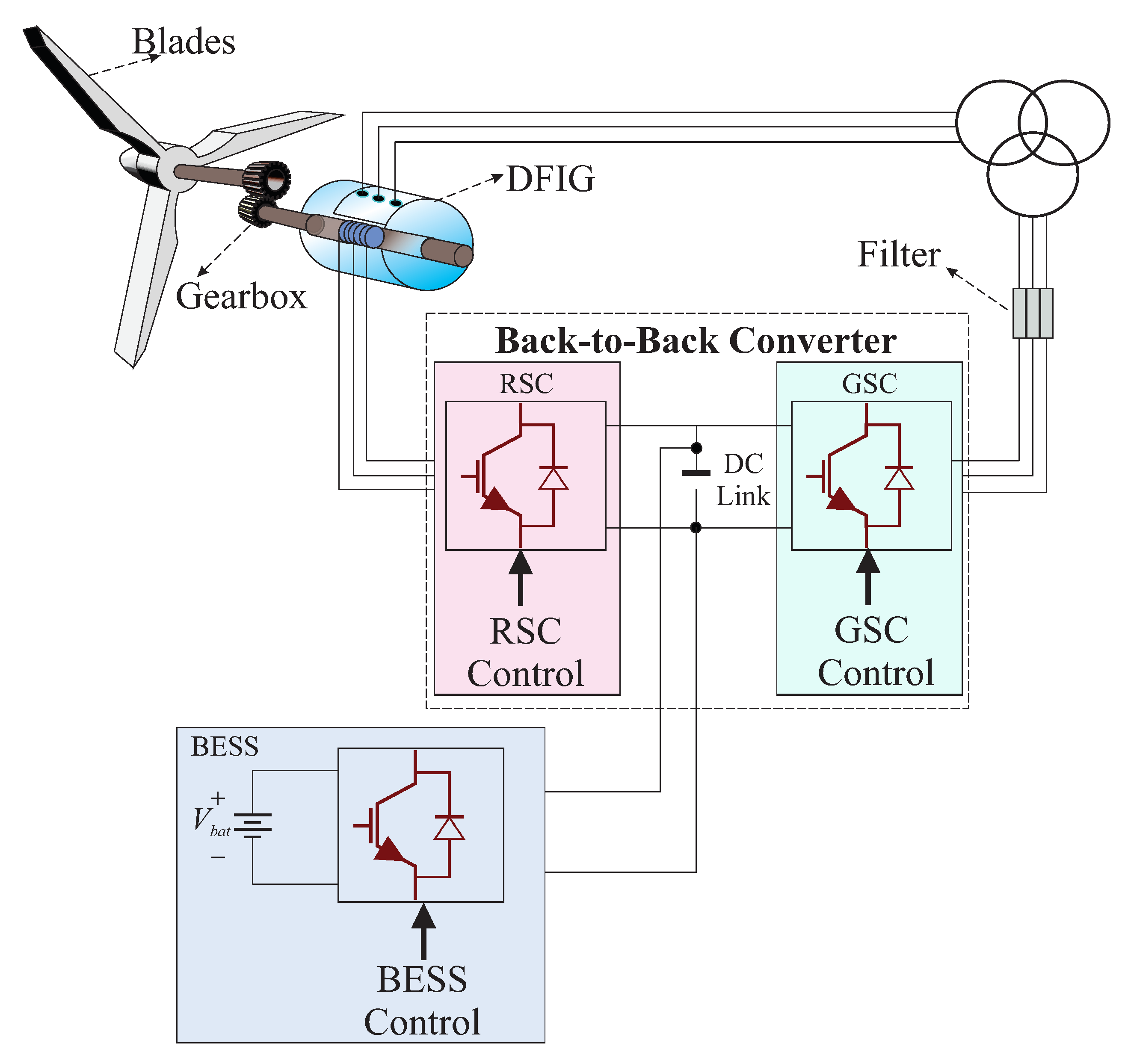
In wind power, the increase in research over the years has led to the development of equipment that makes these systems increasingly flexible and reliable, presenting doubly fed induction generator (DFIG) as one of the most used generators in wind systems. Together with DFIG, energy storage systems (ESS) are being implemented to increase efficiency and thereby meet the energy demand, resulting in a significant increase in the ability of wind power systems to provide ancillary service such as frequency control power in low wind conditions. Figure 1 shows a typical wind energy conversion system composed of a DFIG which has the capacity to operate in variable wind speed conditions, a gearbox in charge of connecting the DFIG with the blades, which captures the kinetic energy contained in the air, two power converters named rotor side converter (RSC) and a grid side converter (GSC) in charge of controlling the flow of power exchanged with the grid and a battery energy storage system (BESS) connected to the DC link of the back-to-back converter. The dynamic representation of the mechanical elements of the wind system (power transmission train, blades, gearbox, slow shaft, and fast shaft) implemented in this work corresponds with the two mass mechanical model presented in [26]. The RSC and GSC correspond with a three-phase two-level converter. The converter is composed of six IGBT with an antiparallel free-wheeling diode for each IGBT.
2.1. Doubly Fed Induction Generator
DFIG is connected to the grid via the stator windings. The stator is directly connected to the grid to inject active and reactive power according to the operating conditions. The rotor terminals are connected to the grid via back-to-back converter consisting of the RSC and GSC converters (see Figure 1). The active and reactive powers injected into the grid as well as the generator rotation are normally controlled through the RSC and its control is done independently [27]. Through the RSC is also implemented the maximum power point tracking (MPPT) controller in order to extract the maximum power for any wind speed. The GSC is usually responsible for maintaining constant DC link voltage to enable the exchange of power between the network and the DFIG [27]. The capacity of this converter is around or of the nominal power of the DFIG and its active and reactive powers can be controlled independently. More information regarding converter functions as well as the DFIG mathematical model can be found in [28].
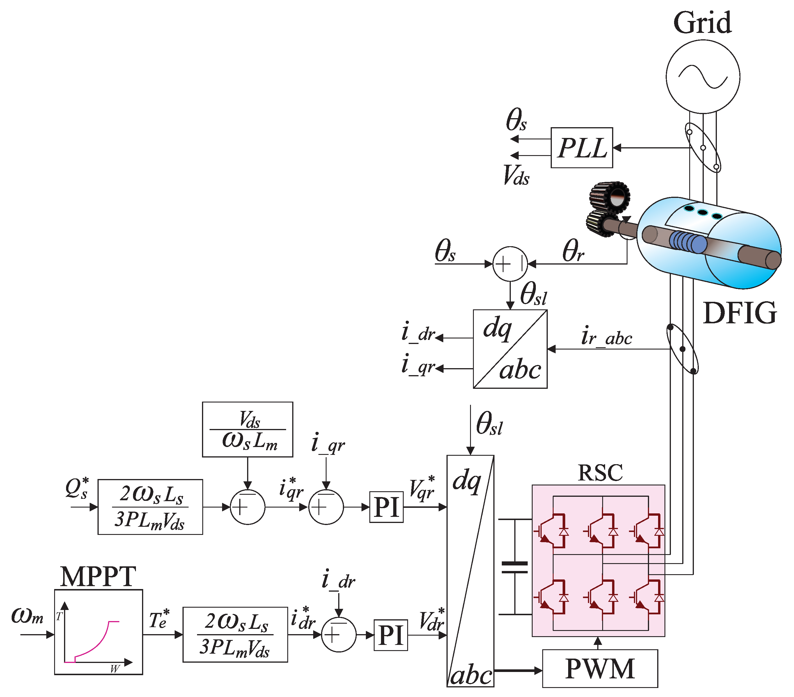
2.1.1. RSC Simplified Model
In order to control the RSC, multiple control strategies can be used [29,30]. However, taking advantage of the fact that the stator is connected directly to the grid, the stator voltage oriented control (SVOC) is used since the frequency and the voltage can be considered constant under normal operating conditions. The SVOC is made by aligning the d-axis of the synchronous reference frame with the stator voltage vector:
The position of the rotor angle is directed to the stator reference frame in the same way that the position of the stator angle is referenced to the stator. The resulting angle between the stator and the rotor voltage vector is the slip angle defined by Equation (2):
Through Equation (2), it is possible to make the frame transformations of and reciprocally as illustrated in Figure 2. As shown in [30], the electromagnetic torque is generated from the MPPT block control and later it will generate the pulses to control the RSC through the control of the current . In the same way, the reactive power generates the pulses to control the RSC through the control of the current .
The maximum power operation is achieved through MPPT with optimal torque control following expression (3), where and are the turbine torque and rotor speed, respectively. Rotor speed is measured and used to calculate the desired torque reference along with the optimal torque coefficient , which depends on the generator parameters. Equations (4) and (5) present these calculations, where G is the gearbox transformation ratio, is the air density, R is the turbine radius, is the maximum turbine power coefficient, and is the optimum tip speed ratio:
In some studies [31,32], several control strategies were incorporated into the RSC to ensure the DFIG participates in the frequency regulation in weak systems or in microgrids; however, the operation at the point of maximum power extraction can be compromised making the system less efficient. In this work, the control of the RSC will not be modified in order not to compromise MPPT.
2.1.2. GSC Simplified Model
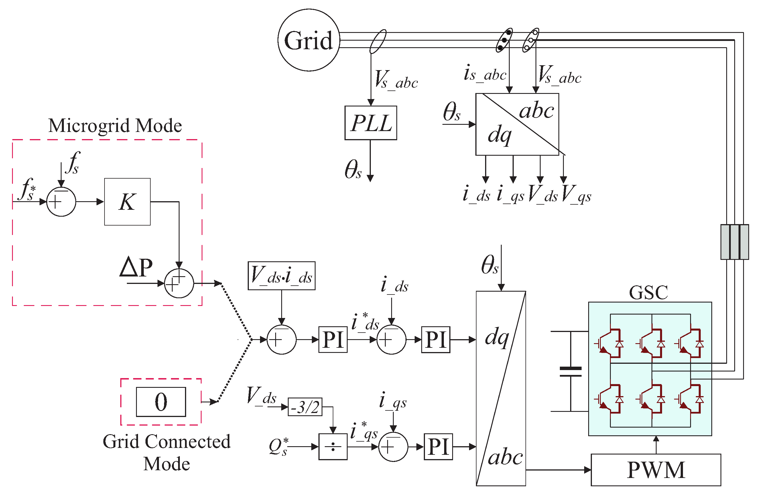
In the same way as RSC, GSC can be controlled through different strategies [26]; however, the strategy used in this work was the voltage oriented control (VOC) [30]. The main function of the GSC under this control method is to maintain the DC link voltage constant regardless of the magnitude and direction of the rotor power. However, in order to provide DFIG with the ability to participate in frequency regulation, the GSC scheme was modified as shown in Figure 3. With the new control loop implemented, the goal now is to control the power the GSC absorbs or injects into the network through the current .
In the grid connected mode, the objective is to determine the ideal condition for charging the battery as a function of the power generated by DFIG available in the GSC. In supersynchronous operation, DFIG usually injects power into the network through the GSC. However, according to the scheme shown in Figure 3, the power exchange between the GSC and the grid is zero. For this reason, the power processed by the GSC is used to charge the battery. In subsynchronous operation, the GSC generally absorbs power from the grid to keep the DC link voltage constant, as the power generated by DFIG is insufficient. Nevertheless, the proposed control presented in Figure 3, the GSC will not absorb grid power, and the control of DC link voltage will be performed by injecting battery power. Consequently, in subsynchronous operation, the battery will not be charged. In microgrid operation mode, the goal is to make DFIG contribute to frequency support at the time of the disturbance by injecting active power resulting from wind speed and battery operation through droop control. For subsynchronous, synchronous, and supersynchronous operation, the power used to control the frequency is , where corresponds to the total power injected by DFIG, is the battery power used by the droop control, and is the difference between the maximum converter power and the power generated by DFIG forwarded by the GSC. Note that these powers have different values for each operating point.
2.1.3. Droop Control
The response of a generating unit to any frequency variation is characterized by its droop. Droop is a percentage that relates the change in frequency and the active power output and is determined from Equation (6):
In the case of DFIG for frequency control, the action of the droop control is made by changes in the active output power during the disturbance. At the moment the power grid disturbance occurs, the frequency variation will cause the DFIG rotor speed to decrease and the kinetic energy stored in the rotary mass to be released, increasing the generator output power. The aim of this work is to keep DFIG at the maximum power point for any operating condition; for this reason, the power required by droop control is obtained through the power supplied by BESS to finally be injected into the electrical system through the GSC. The power value injected from the BESS is controlled by the value of R.
2.2. Battery Energy Storage System
The unpredictable and variable behavior of wind makes wind power unattractive in applications that require constant power injection. Fluctuations in wind speed cause the DFIG to fail to provide power on a regular basis for the network. However, through BESS, DFIG’s wind turbines can provide continuous power to the grid and perform frequency and voltage control tasks even at times of wind speed instability.
BESS Control
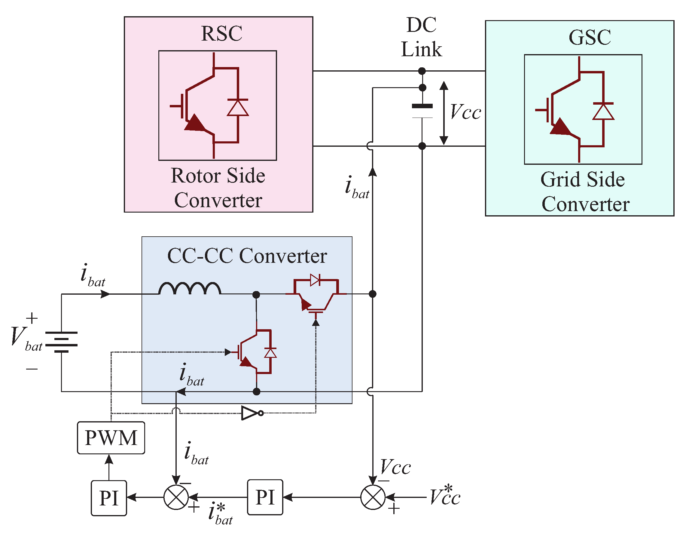
As shown in Figure 4, the battery is connected to the DC link of the back-to-back converter via the CC–CC converter labeled buck-boost. The buck-boost converter is a bidirectional converter in charge of controlling the DC link through the control of the battery current. In the event the DC link voltage increases, the battery will begin to charge, and, in the event the DC link voltage decreases, the battery will provide power.
2.3. Grid Synchronization and Connection
In order to connect the converters to the grid and synchronize the frequency of the converter output signal with the grid frequency, it is essential to know the angle of the grid voltage. One technique that allows this synchronization is Phase Locked Loop (PLL). The PLL output corresponds to the angle required to perform the coordinate transformations of the voltages and currents in the converters by manipulating the grid phase voltages, as shown in Figure 2 and Figure 3 [26,27]. To connect the converters to the grid, in addition to PLL, it is necessary to use a filter. The GSC filter shown in Figure 1 is designed from the philosophy given in [33] and is responsible for communicating with each converter output phase with the grid voltage. This filter operates satisfactorily under full load conditions.
3. Overall Control Scheme for the DFIG and BESS
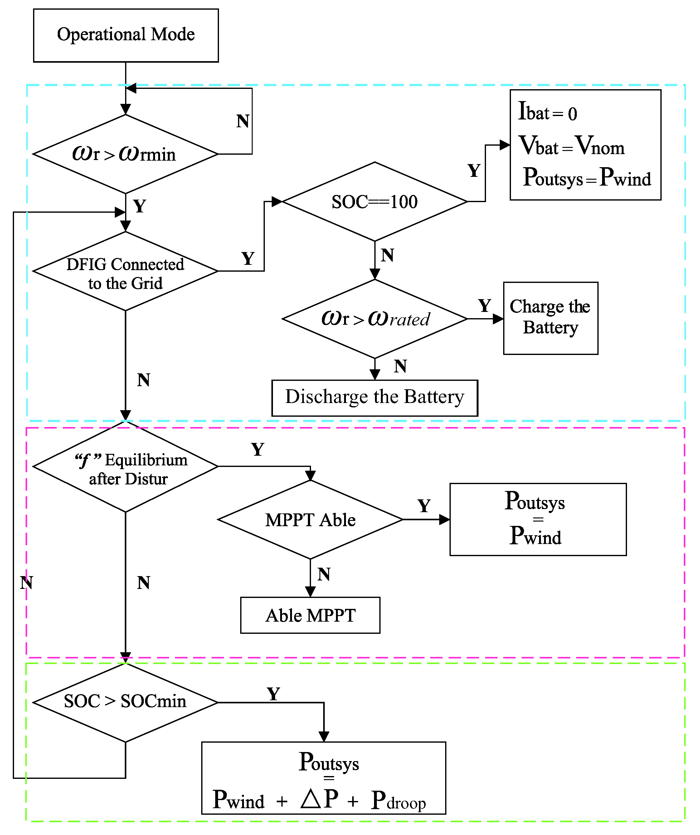
For the DFIG-BESS system shown in Figure 1, the proposed control scheme so that DFIG can absorb/inject active power in grid connected operating mode, and participate in frequency control in addition to feed the loads in microgrid operating mode is presented in Figure 5. In addition, a methodology is also proposed in this scheme in order to charge and/or discharge the battery through the GSC depending on the operating conditions. The control strategy manages the power generated by the wind turbine to charge or discharge the battery when the DFIG is connected in the grid, and the discharge of the battery through droop control to control the frequency of the microgrid mode.
The control system will first monitor the wind speed through the DFIG rotor speed , and take action when the minimum rotation required to keep the system in stable operation is exceeded. The process consists of the following steps:
- The control operates at a time when the DFIG’s rotational speed is above the minimum rotational speed to produce power. If DFIG is connected to the grid, the control asks for the battery state of charge (), since the priority at this point is the battery. If , the control asks if DFIG is in supersynchronous operation (). If the answer is positive, the battery starts charging using the power that goes through the converter. If the operating mode is different from supersynchronous (), the battery discharges to maintain constant DC link voltage without absorbing grid power. If , the power generated by DFIG () is injected into the grid.
- If the DFIG is not connected in the network (the disturbance occurs), the priority is to control the frequency of the microgrid, for which there are two possible situations:(1) Frequency of the microgrid f is in equilibrium: at this point, the microgrid has already reached stability and its frequency is controlled. For this stage, DFIG has as a priority the use of the captured wind power to help feeding the loads that are attached to the microgrid. The total power used to feed the loads corresponds to the power of the DFIG-BESS system plus Synchronous Generator.(2) Frequency of the microgrid f is not in equilibrium: it means that the system is experiencing the disturbance. At this period, the system has a frequency drop due to the power unbalance, and therefore the DFIG must help to restore normal operation of the microgrid. The main objective in this step is to ensure the return of the frequency to its nominal value in the shortest time possible; therefore, the system needs power to perform this task. At first, the control requires the battery to have enough power to support frequency control. If SOC is appropriate (), the power injection from the DFIG to the microgrid at the time of frequency sinking is the sum of the power extracted by the MPPT plus a portion of the battery power plus the power released from the droop (). Only a portion of the battery power is used in order not to exceed the power of the converter.
4. Description of the System Studied
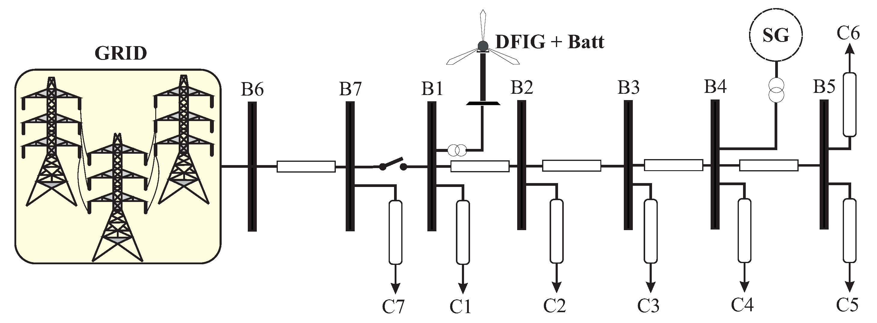
In order to study the impact of the droop control method incorporated in the GSC of the DFIG and the battery connected in the DC link of the back-to-back converter on the frequency of the microgrid, the typical medium voltage distribution system presented in Figure 6 was adopted. Initially, the microgrid composed of the DFIG together with the battery, the synchronous generator (SG) and the loads of constant value over time connected in the buses is connected to the grid. After a period of time, this system is isolated from the network. The total power consumed by the loads of the microgrid is MW and kW. The power consumed by the loads is considered constant since these values represent a critical situation in this system. These values correspond to the time of the day at which the maximum power consumption of the loads on each bar is made. The synchronous generator has a rated power of MWA and the nominal power of the DFIG is MWA. Connected to the DC link of the back-to-back converter, there is a lithium-ion battery with nominal power of 700 kW, rated current of 4000 A and rated voltage of 250 V. The DC link voltage and frequency of the system are 1150 V and 60 Hz, respectively.
5. Simulation Results
The simulations to achieve the optimal behavior of the frequency in the microgrid were developed under different situations.
5.1. Best Value Selection Droop
Since the droop control method depends on the available power, which is strongly influenced by the wind speed, simulations were performed to determine the most suitable droop value for different operating points.
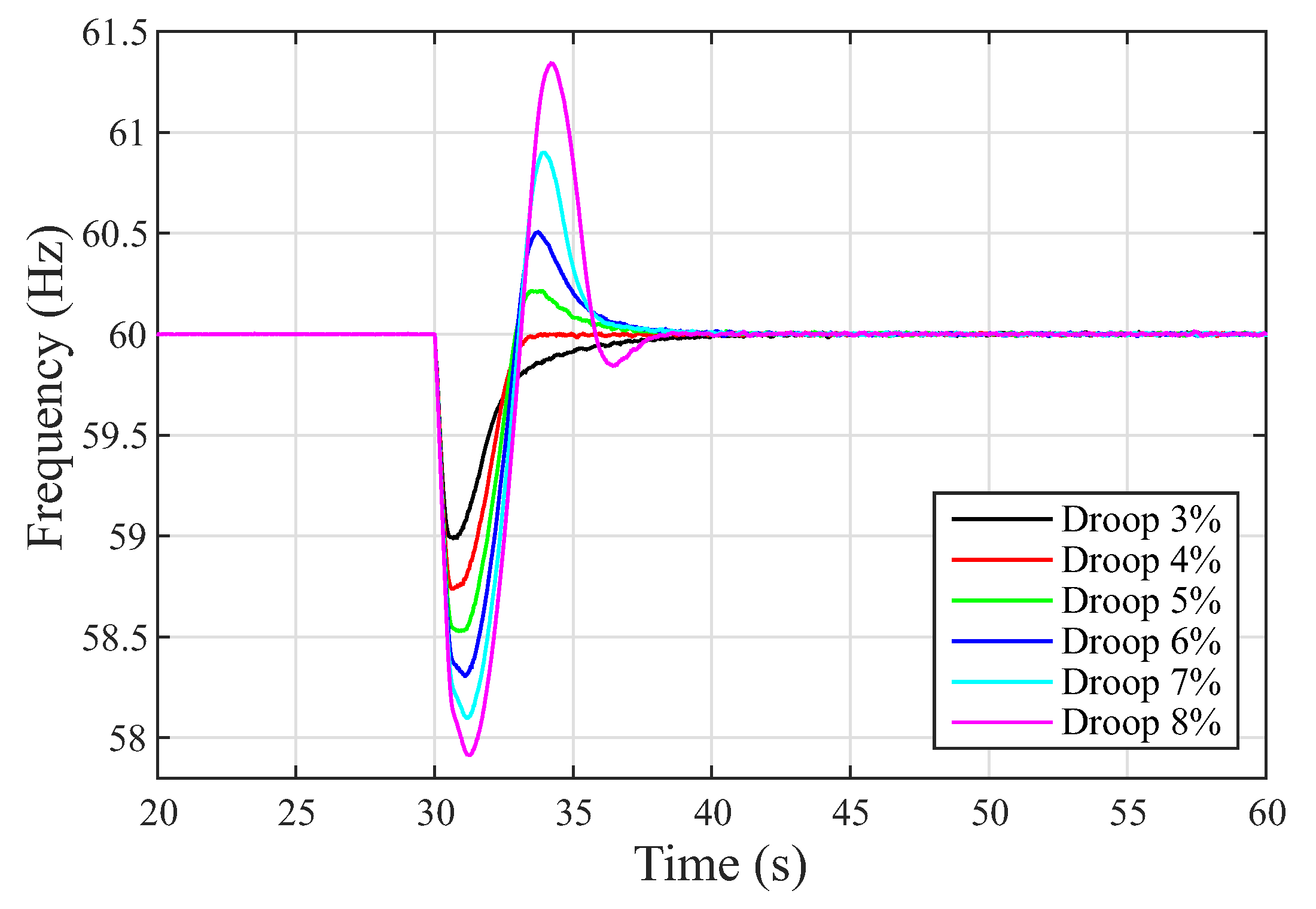
Figure 7 shows the behavior of the microgrid frequency for different droop values when the wind speed is 10 m/s. As shown in Equation (6), a smaller droop value corresponds to a larger injection of power, and, therefore, better performance. Thus, the value of causes the frequency nadir to be smaller.
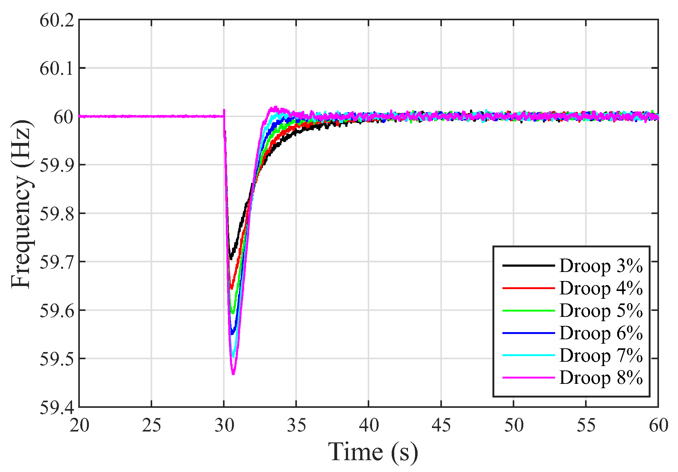
The same situation is shown in Figure 8, which corresponds to the behavior of the microgrid frequency for different droop values when the wind speed is 14 m/s.
Figure 7 and Figure 8 present the results for the minimum and maximum wind speeds used in the analyses, respectively, which shows that, for the wind speeds contained in this range, the droop value that best performs is .
These analyses were performed with the objective of determining the value of droop that will be used to operate along with the battery in frequency control.
5.2. System Frequency Using Droop Control and Delta P
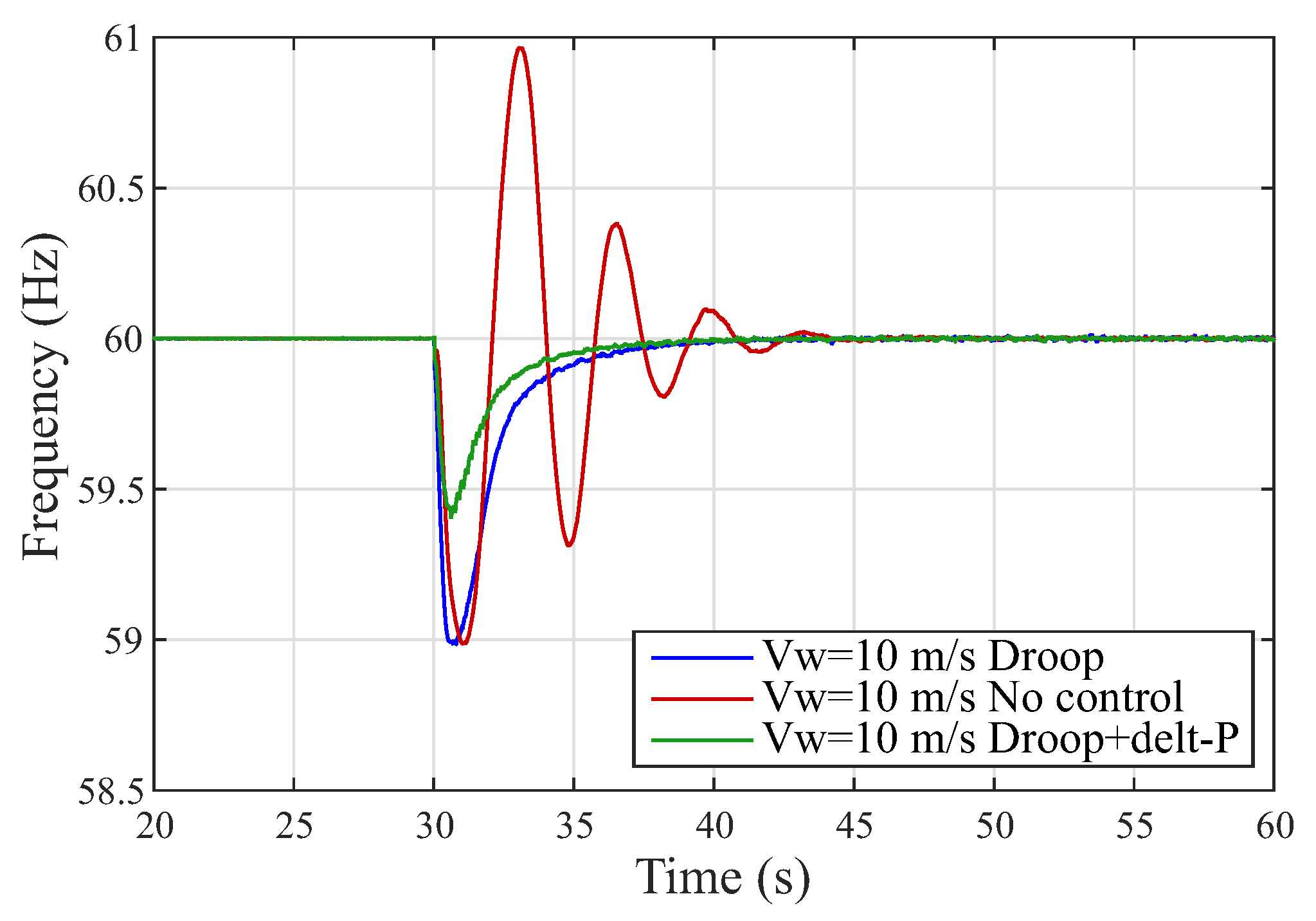
Once the appropriate droop value was selected for each of the wind speeds, simulations were made for three different scenarios. The objective is to compare the performance of the microgrid frequency using DFIG, considering the following assumptions: (1) droop control power injection: for frequency control, the active power delivered by BESS is used through the droop control with the previously selected value, (2) DFIG no control: for frequency control, only the isochronous control of the synchronous generator is used and (3) delta P plus droop control power injection: for frequency control, the active power delivered by BESS is used through the droop control plus the power delta of the converter.
When wind speed decreases in wind power, the ability to maintain normal system operation also decreases. However, Figure 9 shows that it is possible to operate within permissible levels with the aid of alternative equipment and methods. Since DFIG is in subsynchronous operation, the generated power is low. In addition, if the DFIG lacks any control that guarantees an increase in its active output power, the synchronous generator must respond by increasing its power so that it can maintain the frequency of the microgrid. As can be seen from Figure 9, the synchronous generator can control the frequency, although it has an oscillating behavior. When battery power is used through the droop control, the power injection is proportional to the frequency imbalance and so DFIG can help the synchronous generator to improve the frequency behavior. When droop control is used along with delta P, the maximum capacity of the converter is reached; however, the frequency has no oscillations, it has a shorter nadir and shorter accommodation time if compared to the other two controls.
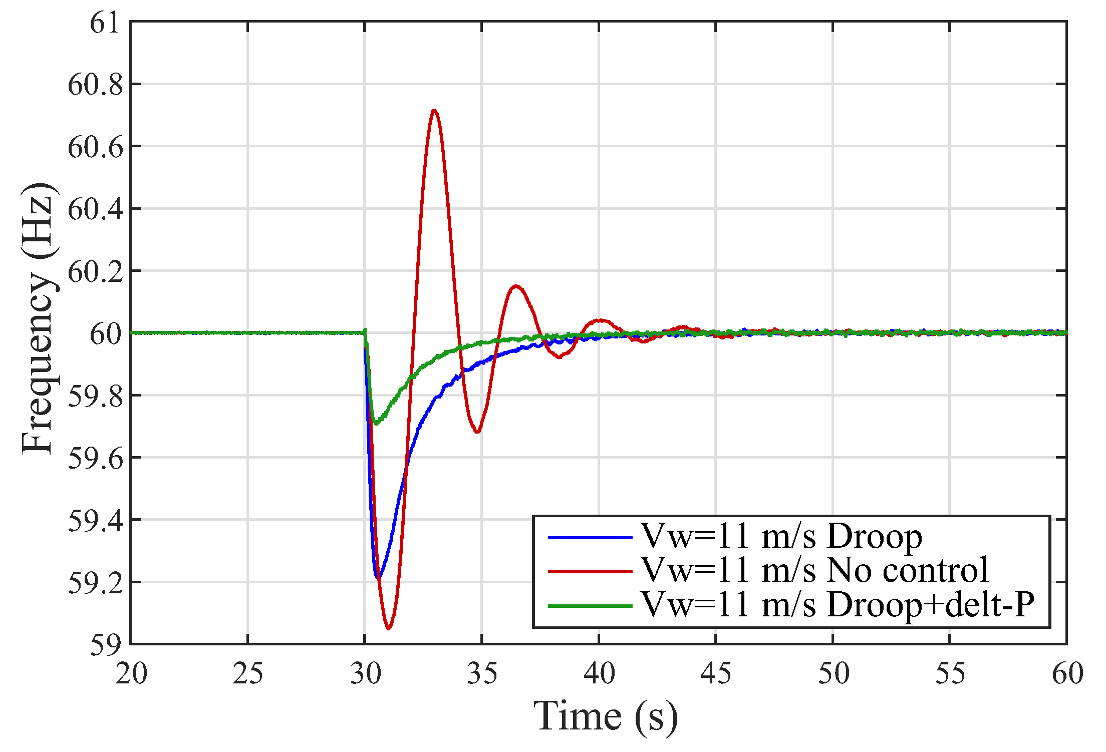
The frequency behavior shown in Figure 10 is similar to the previous case. However, as wind speeds increase, so does DFIG’s ability to contribute to frequency support.
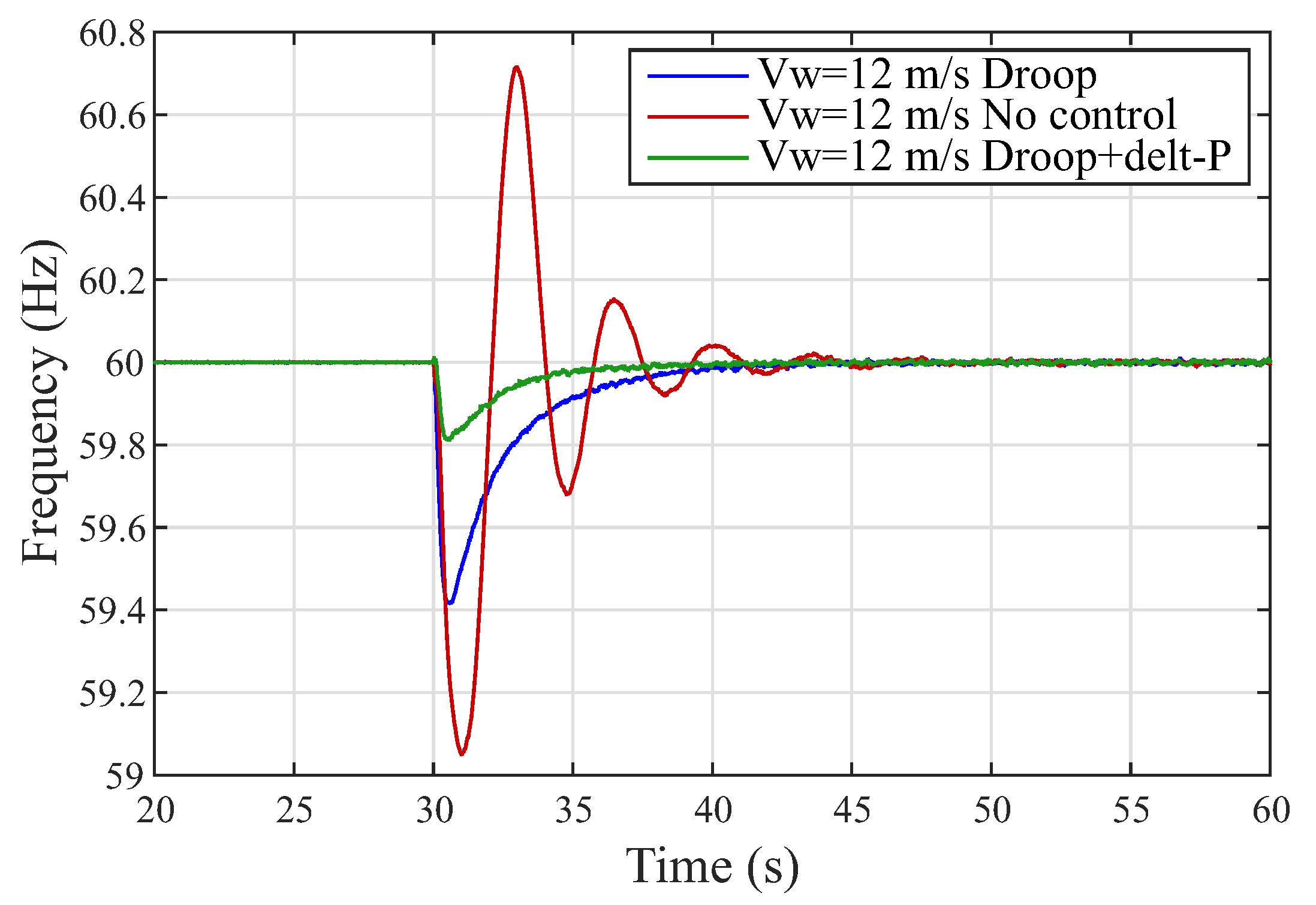
Once the wind speed increases such that the DFIG reaches supersynchronous operation, the output power of the synchronous generator decreases. It happens in order to maintain the same disturbance, regardless of the point of operation. For wind speed of 12 m/s (see Figure 11), the frequency nadir using droop control plus delta P combination continues to exhibit the best behavior compared to the other two methods. The minimum value and accommodation time of the frequency using droop control are approximately Hz and 8 s, respectively. Using droop control plus delta P, the minimum value and accommodation time of the frequency are Hz and 5 s, respectively.
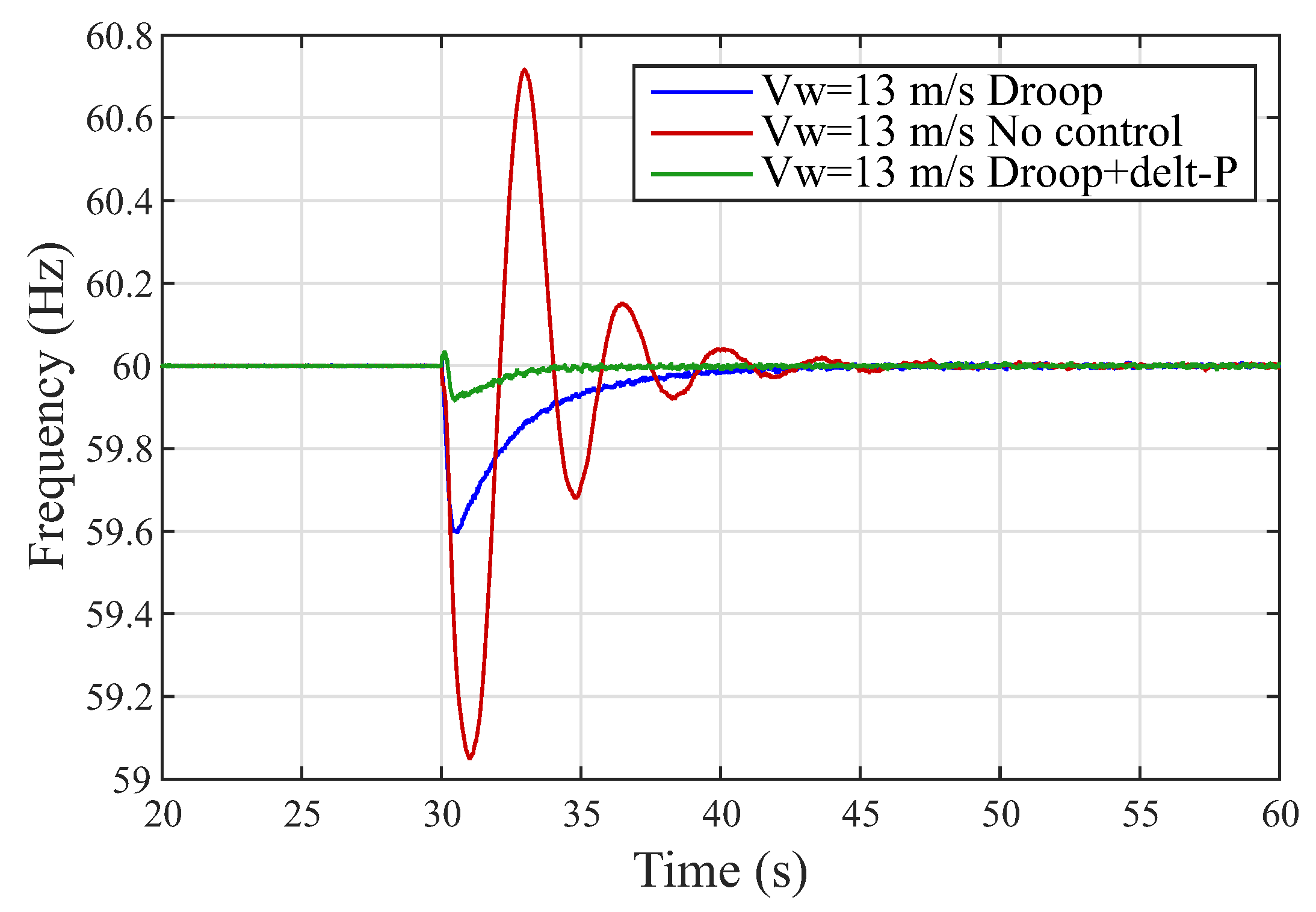
For wind speed of (13 m/s), several characteristics can be observed as shown in Figure 12. The minimum value and accommodation time of the frequency using droop control are approximately Hz and 8 s, respectively. Using droop control plus delta P, the minimum value and accommodation time of the frequency are Hz and 5 s, respectively.
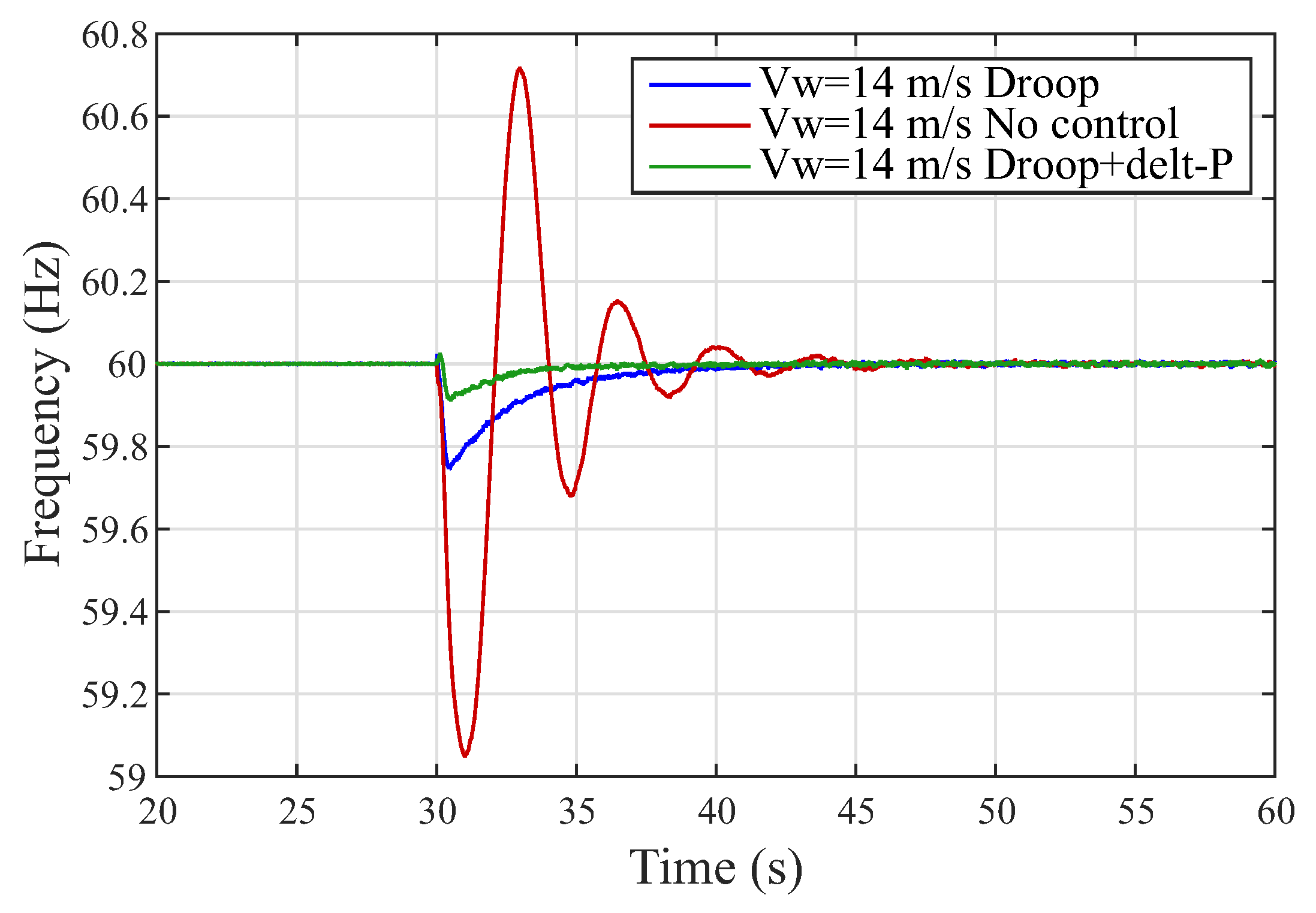
Figure 13 shows the microgrid frequency control result for wind speed of 14 m/s. The minimum value and accommodation time of the frequency using droop control are approximately Hz and 8 s, respectively. Using droop control plus delta P, the minimum value and accommodation time of the frequency are Hz and 5 s, respectively. For super-synchronous operation, a portion of the power generated by DFIG can be used to aid in frequency control and another portion can be used to charge the battery.
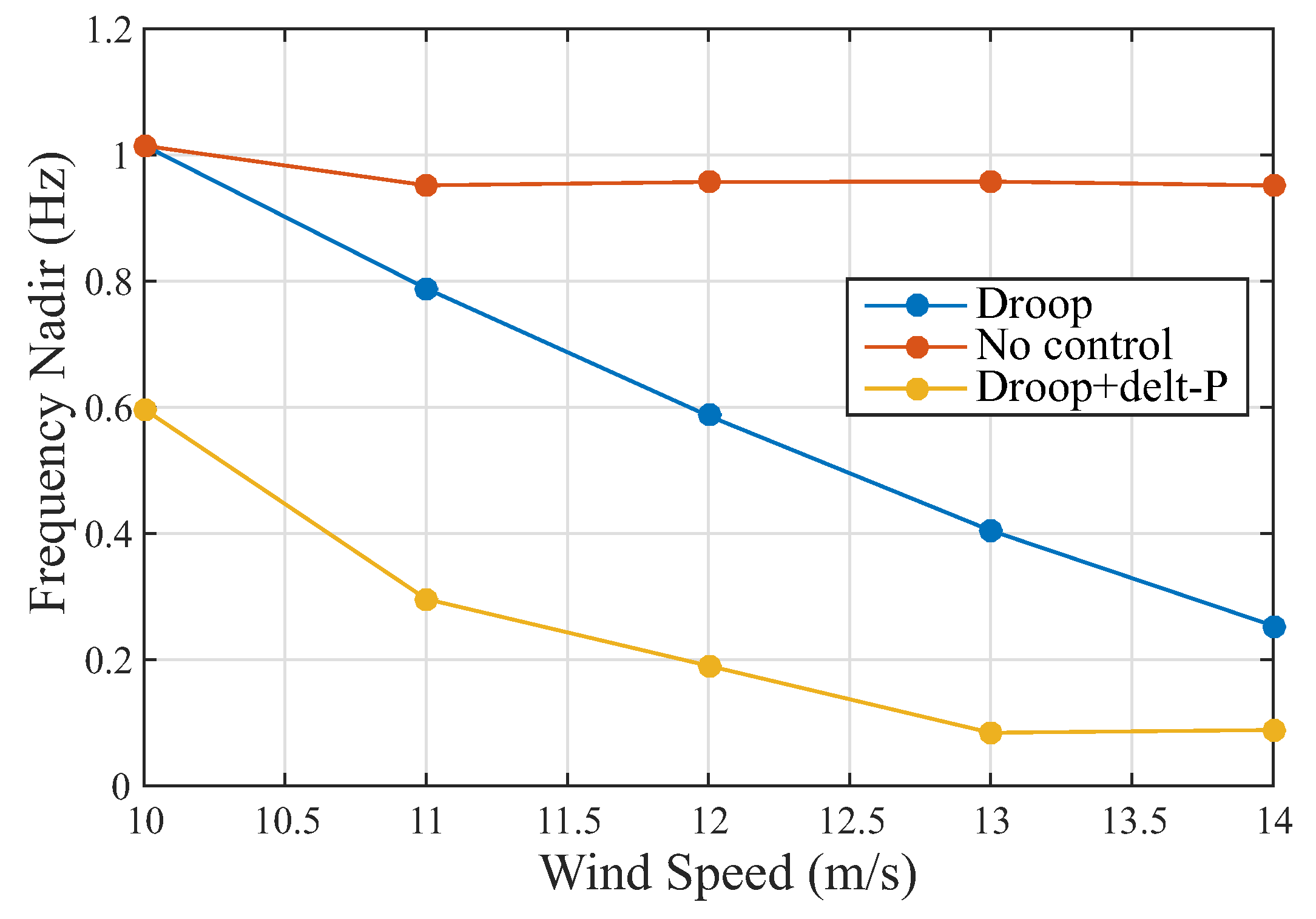
From the tests previously analyzed, the influence of wind speed on frequency control can be clearly evidenced. Figure 14 shows this relationship. Employing only the synchronous generator to control the system frequency at the time of the disturbance, the behavior is oscillatory and with an accommodation time of approximately 10 s for each wind speed. The frequency nadir without DFIG participating in the frequency support is approximately 1 Hz. When the power of droop control plus delta P is used, DFIG participates in frequency control for all wind speed. As wind speed increases, the frequency nadir decreases for the two controls employed. However, droop plus delta P proves to be better. From Figure 14, it can be concluded that, in supersynchronous operation, only the power of the droop control can be used with optimum results. However, for synchronous and subsynchronous operation, it is appropriate to use the droop plus battery combination.
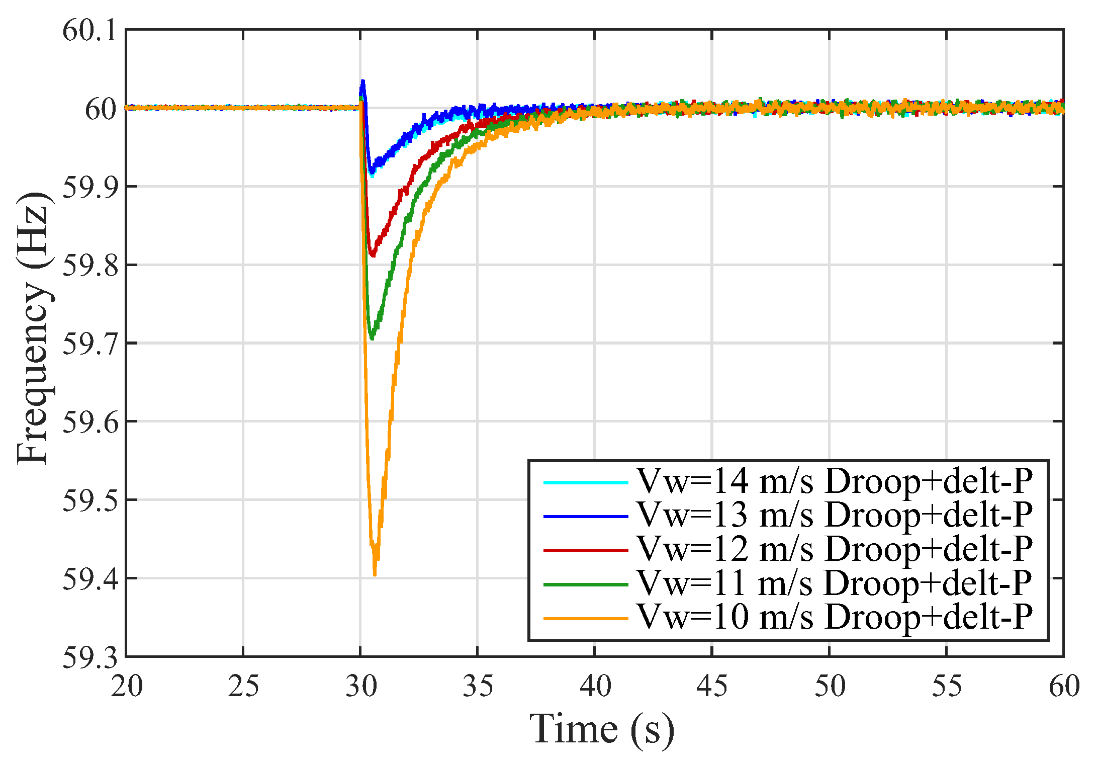
Finally, Figure 15 presents the comparison of frequency behavior for all wind speeds surveyed using the power obtained from the droop control plus delta P. The influence of wind speed on the microgrid frequency is clearly identified. The greater the available wind resource, the lower the power unbalance at the time of operation in microgrid, and, therefore, the frequency variation is smaller.
5.3. Battery Management
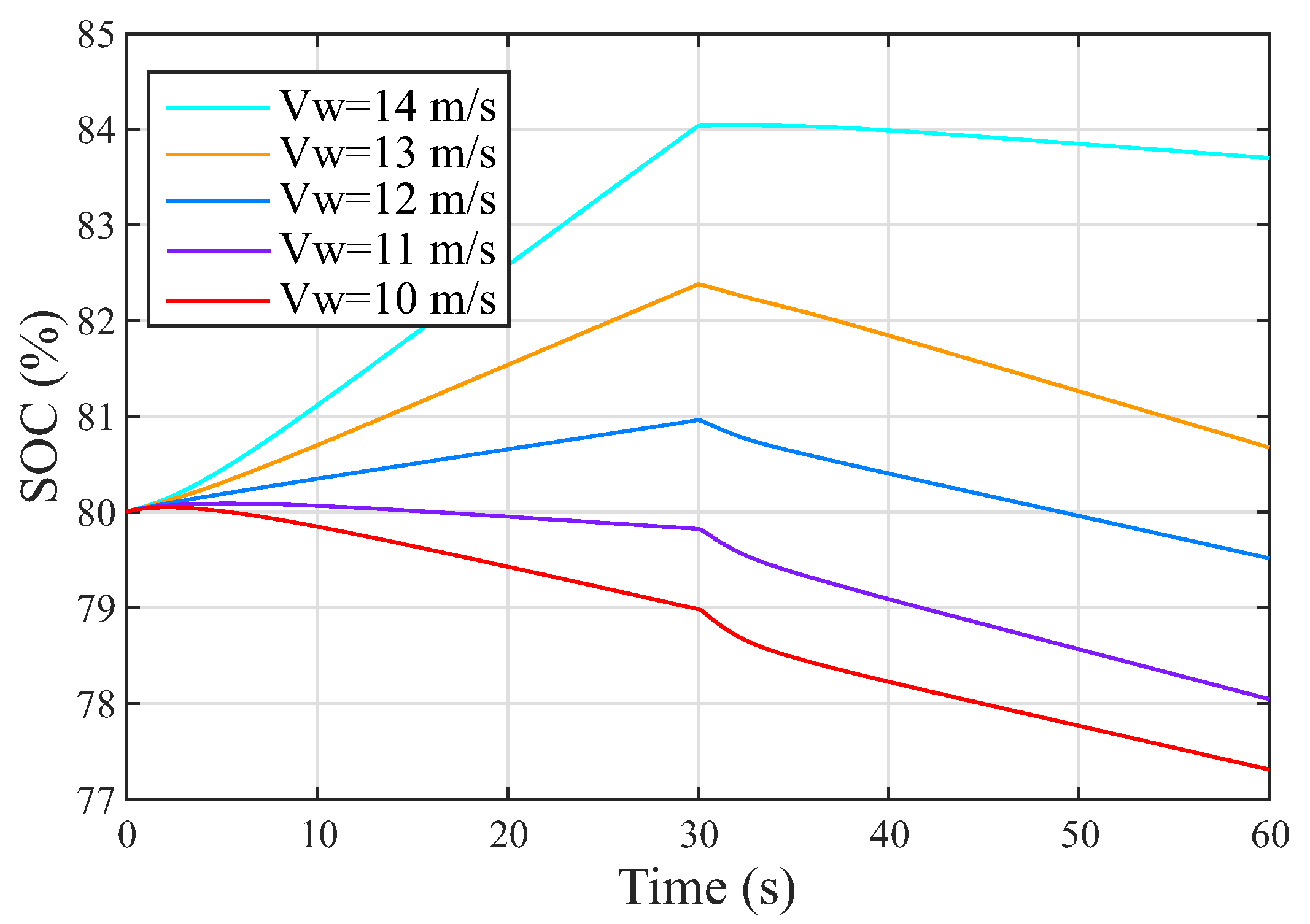
In order to test battery management in the electrical system (network connected and microgrid) over time, Figure 16 and Figure 17 are presented. Figure 16 shows the behavior of the battery state of charge for different wind speeds. The initial value of the SOC is with the DFIG operating on the network. When the rotational speed is below rated speed (subsynchronous operation), the battery must inject power to prevent DC link voltage from decreasing, thus ensuring DFIG stability. Figure 16 shows this behavior for speeds of 10 m/s and 11 m/s. As wind speed increases, DFIG rotation also increases and operates in supersynchronous mode. In this case, the battery must absorb power to prevent the DC link voltage from increasing. In Figure 16, this behavior is shown for 12 m/s, 13 m/s, and 14 m/s. After the disturbance, the battery provides the power required by droop control and loads for all wind speeds.
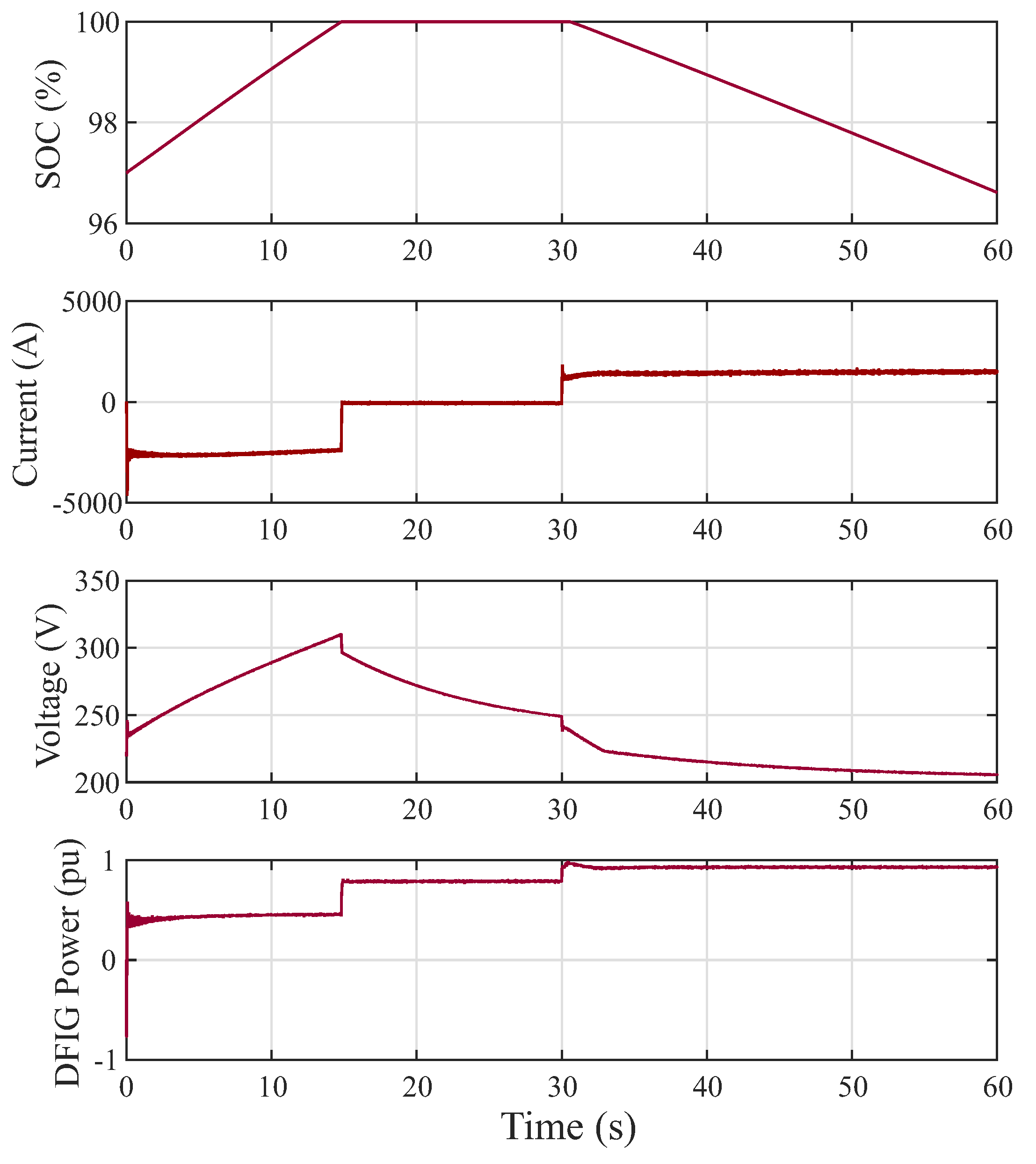
Another event that may occur is if the battery reaches of the charge at the time the DFIG is connected to the network. This fact is presented in Figure 17 for wind speed of 13 m/s and can be analyzed in three steps. The first step corresponds to the battery charge. In this period, the initial SOC of the battery is . The current is negative indicating that the battery is absorbing power by increasing the voltage at its terminals. The second step corresponds to the fully charged battery. At this time, the battery current is zero, the battery voltage returns to its nominal value, and the power of the DFIG used to charge the battery is summed with the total power generated. Finally, the third stage corresponds to the discharge of the battery (moment of the islanding). In this situation, the direction of the current changes indicating that the battery is supplying power to the microgrid and the power output of the DFIG is the power of the DFIG plus the power injected by the battery.
6. Conclusions
A new methodology for controlling the frequency of a microgrid through DFIG was proposed in this paper. The droop control implemented in the GSC together with the BESS connected in the DC link of the back-to-back converter of the DFIG, succeeded in successfully regulating the frequency of the microgrid at the moment of the disturbance. Implementing the droop control in the GSC of DFIG allowed the wind turbine to operate at all times at the point of maximum power extraction, while the power required for frequency control was provided by BESS. From the point of view of frequency control, the droop control showed great results in both super-synchronous and sub-synchronous operation, decreasing the accommodation times and the frequency nadir when compared to the frequency of the microgrid without DFIG intervention. On the other hand, when using BESS, the wind system can become more efficient because when DFIG operates connected to the network and in super-synchronous mode, the battery can be charged while BESS keeps the DC link voltage controlled, in order to maintain stored power to assist in frequency regulation. Finally, for sub-synchronous operation, BESS controls the voltage of the DC link by discharging the battery.
Author Contributions
Conceptualization, L.A.G.G. and A.J.S.F.; methodology, L.A.G.G. and A.P.G.; software, L.A.G.G.; validation, A.P.G., M.B.C.S., and A.J.S.F.; formal analysis, A.P.G. and M.B.C.S.; investigation, L.A.G.G. and A.J.S.F.; resources, M.B.C.S.; writing—original draft preparation, L.A.G.G.; writing—review and editing, L.A.G.G., A.P.G., M.B.C.S., and A.J.S.F.; visualization, A.P.G., M.B.C.S., and A.J.S.F; supervision, A.J.S.F.; project administration, L.A.G.G. and A.J.S.F.; funding acquisition, L.A.G.G., M.B.C.S., and A.J.S.F. All authors have read and agreed to the published version of the manuscript.
Funding
This work was supported by the University of São Paulo, the Federal University of ABC, the CAPES agency, CNPq agency (Process 405757/2018-2,305618/2017-2), and FAPESP agency (2017/04623-3, 2016/08645-9 and 2014/05261-0).
Acknowledgments
This study was financed in part by the coordenação de Aperfeiçoamento de Pessoal de Nível Superior—Brasil (CAPES)—Finance Code 001.
Conflicts of Interest
The authors declare no conflict of interest.
References
- IRENA. Renewable Energy Policies in a Time of Transition; IRENA: Abu Dhabi, UAE, 2018; Volume 4, pp. 62–64. [Google Scholar]
- WWEA. Wind Power Capacity Worldwide Reaches 597 GW, 50.1 GW. 2018. Available online: https://wwindea.org/information-2/information/ (accessed on 16 February 2020).
- Mohseni, M.; Islam, S.M. Review of international grid codes for wind power integration: Diversity, technology and a case for global standard. Renew. Sustain. Energy Rev. 2012, 16, 3876–3890. [Google Scholar] [CrossRef]
- Wang, Z.; Wong, K.P.; Choi, S.; Gan, D.; Zong, Y. An overview of codes and control strategies for frequency regulation in wind power generation. In Smart Power Distribution Systems; Yang, Q., Yang, T., Li, W., Eds.; Academic Press: Cambridge, MA, USA, 2019; pp. 3–20. [Google Scholar] [CrossRef]
- Yang, D.; Kim, J.; Kang, Y.C.; Muljadi, E.; Zhang, N.; Hong, J.; Song, S.; Zheng, T. Temporary Frequency Support of a DFIG for High Wind Power Penetration. IEEE Trans. Power Syst. 2018, 33, 3428–3437. [Google Scholar] [CrossRef]
- Atwa, Y.M.; El-Saadany, E.F. Optimal Allocation of ESS in Distribution Systems With a High Penetration of Wind Energy. IEEE Trans. Power Syst. 2010, 25, 1815–1822. [Google Scholar] [CrossRef]
- Li, Y.; Zhang, Z.; Yang, Y.; Li, Y.; Chen, H.; Xu, Z. Coordinated control of wind farm and VSC–HVDC system using capacitor energy and kinetic energy to improve inertia level of power systems. Int. J. Electr. Power Energy Syst. 2014, 59, 79–92. [Google Scholar] [CrossRef]
- Gholamrezaie, V.; Dozein, M.G.; Monsef, H.; Wu, B. An Optimal Frequency Control Method Through a Dynamic Load Frequency Control (LFC) Model Incorporating Wind Farm. IEEE Syst. J. 2018, 12, 392–401. [Google Scholar] [CrossRef]
- Shahabi, M.; Haghifam, M.R.; Mohamadian, M.; Nabavi-Niaki, S.A. Microgrid Dynamic Performance Improvement Using a Doubly Fed Induction Wind Generator. IEEE Trans. Energy Convers. 2009, 24, 137–145. [Google Scholar] [CrossRef]
- Han, Y.; Ha, J. Droop Control Using Impedance of Grid-Integrated DFIG within Microgrid. IEEE Trans. Energy Convers. 2019, 34, 88–97. [Google Scholar] [CrossRef]
- Yang, J.; Chen, Y.; Hsu, Y. Small-signal stability analysis and particle swarm optimisation self-tuning frequency control for an islanding system with DFIG wind farm. IET Gener. Transm. Distrib. 2019, 13, 563–574. [Google Scholar] [CrossRef]
- Zhao, J.; Lyu, X.; Fu, Y.; Hu, X.; Li, F. Coordinated Microgrid Frequency Regulation Based on DFIG Variable Coefficient Using Virtual Inertia and Primary Frequency Control. IEEE Trans. Energy Convers. 2016, 31, 833–845. [Google Scholar] [CrossRef]
- Tan, Y.; Meegahapola, L.; Muttaqi, K.M. A Suboptimal Power-Point-Tracking-Based Primary Frequency Response Strategy for DFIGs in Hybrid Remote Area Power Supply Systems. IEEE Trans. Energy Convers. 2016, 31, 93–105. [Google Scholar] [CrossRef]
- Fakhari Moghaddam Arani, M.; Mohamed, Y.A.I. Dynamic Droop Control for Wind Turbines Participating in Primary Frequency Regulation in Microgrids. IEEE Trans. Smart Grid 2018, 9, 5742–5751. [Google Scholar] [CrossRef]
- Hwang, M.; Muljadi, E.; Park, J.; Sorensen, P.; Kang, Y.C. Dynamic Droop—Based Inertial Control of a Doubly-Fed Induction Generator. IEEE Trans. Sustain. Energy 2016, 7, 924–933. [Google Scholar] [CrossRef]
- Liu, J.; Wang, X. Analytical determination of stable droop loop gain for a DFIG participating in frequency regulation. J. Eng. 2017, 2017, 1447–1452. [Google Scholar] [CrossRef]
- Mesbahi, T.; Ouari, A.; Ghennam, T.; Berkouk, E.M.; Rizoug, N.; Mesbahi, N.; Meradji, M. A stand-alone wind power supply with a Li-ion battery energy storage system. Renew. Sustain. Energy Rev. 2014, 40, 204–213. [Google Scholar] [CrossRef]
- Mendis, N.; Muttaqi, K.M.; Perera, S. Active power management of a super capacitor-battery hybrid energy storage system for standalone operation of DFIG based wind turbines. In Proceedings of the 2012 IEEE Industry Applications Society Annual Meeting, Las Vegas, NV, USA, 7–11 October 2012; pp. 1–8. [Google Scholar] [CrossRef]
- Mendis, N.; Muttaqi, K.M.; Perera, S. Management of Low- and High-Frequency Power Components in Demand-Generation Fluctuations of a DFIG-Based Wind-Dominated RAPS System Using Hybrid Energy Storage. IEEE Trans. Ind. Appl. 2014, 50, 2258–2268. [Google Scholar] [CrossRef]
- Miao, L.; Wen, J.; Xie, H.; Yue, C.; Lee, W. Coordinated Control Strategy of Wind Turbine Generator and Energy Storage Equipment for Frequency Support. IEEE Trans. Ind. Appl. 2015, 51, 2732–2742. [Google Scholar] [CrossRef]
- Knap, V.; Sinha, R.; Swierczynski, M.; Stroe, D.; Chaudhary, S. Grid inertial response with Lithium-ion battery energy storage systems. In Proceedings of the 2014 IEEE 23rd International Symposium on Industrial Electronics (ISIE), Istambul, Turkey, 1–4 June 2014; pp. 1817–1822. [Google Scholar] [CrossRef] [Green Version]
- Peng, B.; Zhang, F.; Liang, J.; Ding, L.; Liang, Z.; Wu, Q. Coordinated control strategy for the short-term frequency response of a DFIG-ES system based on wind speed zone classification and fuzzy logic control. Int. J. Electr. Power Energy Syst. 2019, 107, 363–378. [Google Scholar] [CrossRef]
- Zou, Y.; Elbuluk, M.E.; Sozer, Y. Stability Analysis of Maximum Power Point Tracking (MPPT) Method in Wind Power Systems. IEEE Trans. Ind. Appl. 2013, 49, 1129–1136. [Google Scholar] [CrossRef]
- Naidu, N.K.S.; Singh, B. Grid-Interfaced DFIG-Based Variable Speed Wind Energy Conversion System With Power Smoothening. IEEE Trans. Sustain. Energy 2017, 8, 51–58. [Google Scholar] [CrossRef]
- Tiwari, S.K.; Singh, B.; Goel, P.K. Design and Control of Autonomous Wind–Solar System With DFIG Feeding 3-Phase 4-Wire Loads. IEEE Trans. Ind. Appl. 2018, 54, 1119–1127. [Google Scholar] [CrossRef]
- Abad, G.; Lopez, J.; Rodriguez, M.; Marroyo, L.; Iwanski, G. Doubly Fed Induction Machine: Modeling and Control for Wind Energy Generation; John Wiley & Sons: Hoboken, NJ, USA, 2011; Volume 85. [Google Scholar]
- Yazdani, A.; Iravani, R. Voltage-Sourced Converters in Power Systems; Wiley Online Library: Hoboken, NJ, USA, 2010; Volume 34. [Google Scholar]
- Xu, L.; Wang, Y. Dynamic modeling and control of DFIG-based wind turbines under unbalanced network conditions. IEEE Trans. Power Syst. 2007, 22, 314–323. [Google Scholar] [CrossRef]
- Eltigani, D.; Masri, S. Challenges of integrating renewable energy sources to smart grids: A review. Renew. Sustain. Energy Rev. 2015, 52, 770–780. [Google Scholar] [CrossRef]
- Wu, B.; Lang, Y.; Zargari, N.; Kouro, S. Power Conversion and Control of Wind Energy Systems; John Wiley & Sons: Hoboken, NJ, USA, 2011; Volume 76. [Google Scholar]
- Ramtharan, G.; Jenkins, N.; Ekanayake, J. Frequency support from doubly fed induction generator wind turbines. IET Renew. Power Gener. 2007, 1, 3–9. [Google Scholar] [CrossRef]
- Zhang, Z.S.; Sun, Y.Z.; Lin, J.; Li, G.J. Coordinated frequency regulation by doubly fed induction generator-based wind power plants. IET Renew. Power Gener. 2012, 6, 38–47. [Google Scholar] [CrossRef]
- Mishra, P.; Maheshwari, R. Design, Analysis, and Impacts of Sinusoidal LC Filter on Pulse Width Modulated Inverter Fed Induction Motor Drive. IEEE Trans. Ind. Electron. 2019, 7, 2678–2688. [Google Scholar] [CrossRef]
Figure 1.
DFIG wind system plus BESS.

Figure 2.
Control diagram for RSC.

Figure 3.
Control diagram for GSC.

Figure 4.
Control diagram for BESS.

Figure 5.
Coordinated control scheme for DFIG and BESS to provide frequency support and battery charging and discharging.
Figure 5.
Coordinated control scheme for DFIG and BESS to provide frequency support and battery charging and discharging.

Figure 6.
General distribution system.

Figure 7.
Frequency behavior with variation of the droop value for a wind speed of 10 m/s.

Figure 8.
Frequency behavior with variation of the droop value for a wind speed of 14 m/s.

Figure 9.
Frequency comparison for wind speed of 10 m/s.

Figure 10.
Frequency comparison for wind speed of 11 m/s.

Figure 11.
Frequency comparison for wind speed of 12 m/s.

Figure 12.
Frequency comparison for wind speed of 13 m/s.

Figure 13.
Frequency comparison for wind speed of 14 m/s.

Figure 14.
Frequency nadir as a function of wind speed.

Figure 15.
Comparison of best frequency performance using battery plus droop for all wind speeds.

Figure 16.
80% initial battery SOC for all wind speeds.

Figure 17.
Battery SOC reaches 100%.

© 2020 by the authors. Licensee MDPI, Basel, Switzerland. This article is an open access article distributed under the terms and conditions of the Creative Commons Attribution (CC BY) license (http://creativecommons.org/licenses/by/4.0/).
Share and Cite
MDPI and ACS Style
Gomez, L.A.G.; Grilo, A.P.; Salles, M.B.C.; Sguarezi Filho, A.J. Combined Control of DFIG-Based Wind Turbine and Battery Energy Storage System for Frequency Response in Microgrids. Energies 2020, 13, 894. https://doi.org/10.3390/en13040894
AMA Style
Gomez LAG, Grilo AP, Salles MBC, Sguarezi Filho AJ. Combined Control of DFIG-Based Wind Turbine and Battery Energy Storage System for Frequency Response in Microgrids. Energies. 2020; 13(4):894. https://doi.org/10.3390/en13040894
Chicago/Turabian StyleGomez, Luis. A. G., Ahda P. Grilo, M. B. C. Salles, and A. J. Sguarezi Filho. 2020. "Combined Control of DFIG-Based Wind Turbine and Battery Energy Storage System for Frequency Response in Microgrids" Energies 13, no. 4: 894. https://doi.org/10.3390/en13040894
Note that from the first issue of 2016, this journal uses article numbers instead of page numbers. See further details here.