Article

1D Simulation and Experimental Analysis on the Effects of the Injection Parameters in Methane–Diesel Dual-Fuel Combustion

by
Javier Monsalve-Serrano
1,*,
Giacomo Belgiorno
2,
Gabriele Di Blasio
2 and
María Guzmán-Mendoza
1
1
CMT - Motores Térmicos, Universitat Politècnica de València, Camino de Vera s/n, 46022 Valencia, Spain
2
Istituto Motori, Consiglio Nazionale Delle Ricerche, Via G. Marconi 4, 80125 Naples, Italy
*
Author to whom correspondence should be addressed.
Energies 2020, 13(14), 3734; https://doi.org/10.3390/en13143734
Submission received: 3 June 2020 / Revised: 15 July 2020 / Accepted: 17 July 2020 / Published: 20 July 2020
(This article belongs to the Special Issue Research and Development in Single-Cylinder Engines)

Abstract

:
Notwithstanding the policies that move towards electrified powertrains, the transportation sector mainly employs internal combustion engines as the primary propulsion system. In this regard, for medium- to heavy-duty applications, as well as for on- and off-road applications, diesel engines are preferred because of the better efficiency, lower CO2, and greater robustness compared to spark-ignition engines. Due to its use at a large scale, the internal combustion engines as a source of energy depletion and pollutant emissions must further improved. In this sense, the adoption of alternative combustion concepts using cleaner fuels than diesel (e.g., natural gas, ethanol and methanol) presents a viable solution for improving the efficiency and emissions of the future powertrains. Particularly, the methane–diesel dual-fuel concept represents a possible solution for compression ignition engines because the use of the low-carbon methane fuel, a main constituent of natural gas, as primary fuel significantly reduces the CO2 emissions compared to conventional liquid fuels. Nonetheless, other issues concerning higher total hydrocarbon (THC) and CO emissions, mainly at low load conditions, are found. To minimize this issue, this research paper evaluates, through a new and alternative approach, the effects of different engine control parameters, such as rail pressure, pilot quantity, start of injection and premixed ratio in terms of efficiency and emissions, and compared to the conventional diesel combustion mode. Indeed, for a deeper understanding of the results, a 1-Dimensional spray model is used to model the air-fuel mixing phenomenon in response to the variations of the calibration parameters that condition the subsequent dual-fuel combustion evolution. Specific variation settings, in terms of premixed ratio, injection pressure, pilot quantity and combustion phasing are proposed for further efficiency improvements.

1. Introduction

The higher efficiency of the compression ignition (CI) engines compared to the spark ignition (SI) engines justifies the spread of this propulsion system in the transport sector. However, regarding the emissions, CI engines operating under conventional diesel combustion (CDC) are characterized by the well-known NOx-soot trade-off, which imposes the manufacturers to couple the vehicle with complex aftertreatment systems (ATS)—diesel oxidation catalyst, diesel particulate filter and selective catalytic reduction—to meet the severe pollutant emission standards imposed by the legislation [1]. It has to be considered that the use of ATS increases the overall cost and decreases global efficiency due to the higher pumping work required and the need of using extra fluids (diesel fuel, ammonia, urea, etc.), at the expense of CO2, in comparison to SI engines [2]. For these reasons, in the field of internal combustion engines (ICE), there is an important interest in studying and applying advanced combustion concepts [3,4,5] and specific fuels to face the issues encountered with the conventional technologies [6,7].
Within the advanced combustion strategies, several low temperature combustion (LTC) concepts have been widely investigated, such as reactivity controlled compression ignition (RCCI), homogeneous charge compression ignition (HCCI) and partially premixed combustion (PPC). The PPC concept, applied to ICEs, is prospectively able to simultaneously reduce the NOx and soot emissions, shorten the combustion duration and reduce heat transfer losses inside the cylinder as compared to CDC [8,9]. Other studies combine the LTC concepts with alternative fuels (natural gas, ethanol, methanol, butanol, etc.) demonstrating the simultaneous improvements in efficiency, NOx and soot emissions [9,10,11].
The dual-fuel combustion mode uses two fuels, a low reactivity and a high reactivity one, for example, natural gas and diesel fuel, to promote the combustion process. Fitted to the intake manifold is a port fuel injector, through which the low reactivity fuel is injected. The low reactivity fuel is thus premixed with the in-cylinder charge in the course of the intake stroke, while the high reactivity fuel is injected into the combustion chamber directly. The dual-fuel natural gas–diesel combustion concept can be roughly divided into three stages [12,13]; a charge of air and natural gas compresses, and close to the top dead center (TDC), a pilot injection of diesel fuel (a small quantity) is injected into the cylinder to mix with the air-gas composition throughout the delay of the ignition. Following this delay, the diesel fuel ignites due to the high temperature inside the cylinder, which consequently initiates the burning the natural gas. Thus, the combustion evolves through the propagation of flames. This dual-fuel combustion has been found to have the potential to deliver efficiency peaks typical of CI engines and low CO2 emissions due to the usage of natural gas instead of diesel fuel. In this sense, previous works have shown CO2 reductions up to 10% compared to CDC when operated with a premixed ratio of 50% [14]. Other studies reporting the application of the dual-fuel concept for light-duty engines also highlight the issues concerning higher THC and CO emissions, compared to CDC [15,16]. In this sense, other works concluded, through dedicated design of experiments on the engine control parameters (exhaust gas recirculation, diesel injection parameters, combustion phasing, etc.), that the THCs are strictly related to the amount of the methane slip, and consequence of the air to fuel ratio, EGR rate and maximum in-cylinder pressure parameters [17,18,19,20].
Based on these results, this work aims to further investigate on the in-cylinder phenomenon employing an innovative approach mixture interaction with particular reference to the ignition process, evaluating the mixture distribution and relating it to the emissions and engine control parameters, such as the diesel pilot injection quantity, premixed ratio, injection pressure and combustion phasing, to take advantage for the optimization of the combustion process.

2. Materials and Methods

2.1. Engine, Test Cell and Fuels Characteristics

The research activities have been performed using a specific designed single-cylinder engine (SCE) test-rig with a modern combustion system architecture derived from a reference multi-cylinder light duty diesel engine (MCE). Reliable correlation between the SCE and MCE outcomes have been adopted to make the results directly transferrable to real MCE applications. A dedicated LabVIEW®-based code serves as a controller for the engine parameters (fuel injection, boost, and backpressure, etc.) and as a monitor of the overall engine thermodynamic conditions and engine-out emissions. For the dual-fuel application, the engine has been equipped with an additional port fuel injection system for natural gas application capable to operate at 8 bar of fuel injection pressure. The fuel flows are measured by means of a gravimetric fuel balance (AVL 733), in the case of diesel, and a thermal mass flow meter (Brooks SLA 5860), in the case of natural gas. To increase the accuracy of the air mass flow measurement, an ABB FMT thermal mass and Emerson Coriolis mass flowmeters with different ranges are installed. The geometrical engine characteristics are reported in Table 1.
The in-cylinder pressure is measured through a piezo-quartz transducer (Kistler 6125B) and synchronized with a high resolution (0.1 CAD) optical encoder. The pressure signals are averaged over 128 consecutive cycles. The real-time calculation of the heat release and heat release rate is based on the measured in-cylinder pressure [21] using high-frequency AVL hardware and software tools. An AVL 415S smoke-meter is used to measure the smoke while the gaseous emissions are measured through an AVL CEB II emission test bench.
Commercial diesel fuel and pure methane (CH4) were used as direct and port injected fuel, respectively. The use of methane avoids introducing uncertainties associated to the natural gas composition, which is constituted by a mix of hydrocarbons that depend on the fuel source. The fuels characteristics of interest are listed in Table 2.

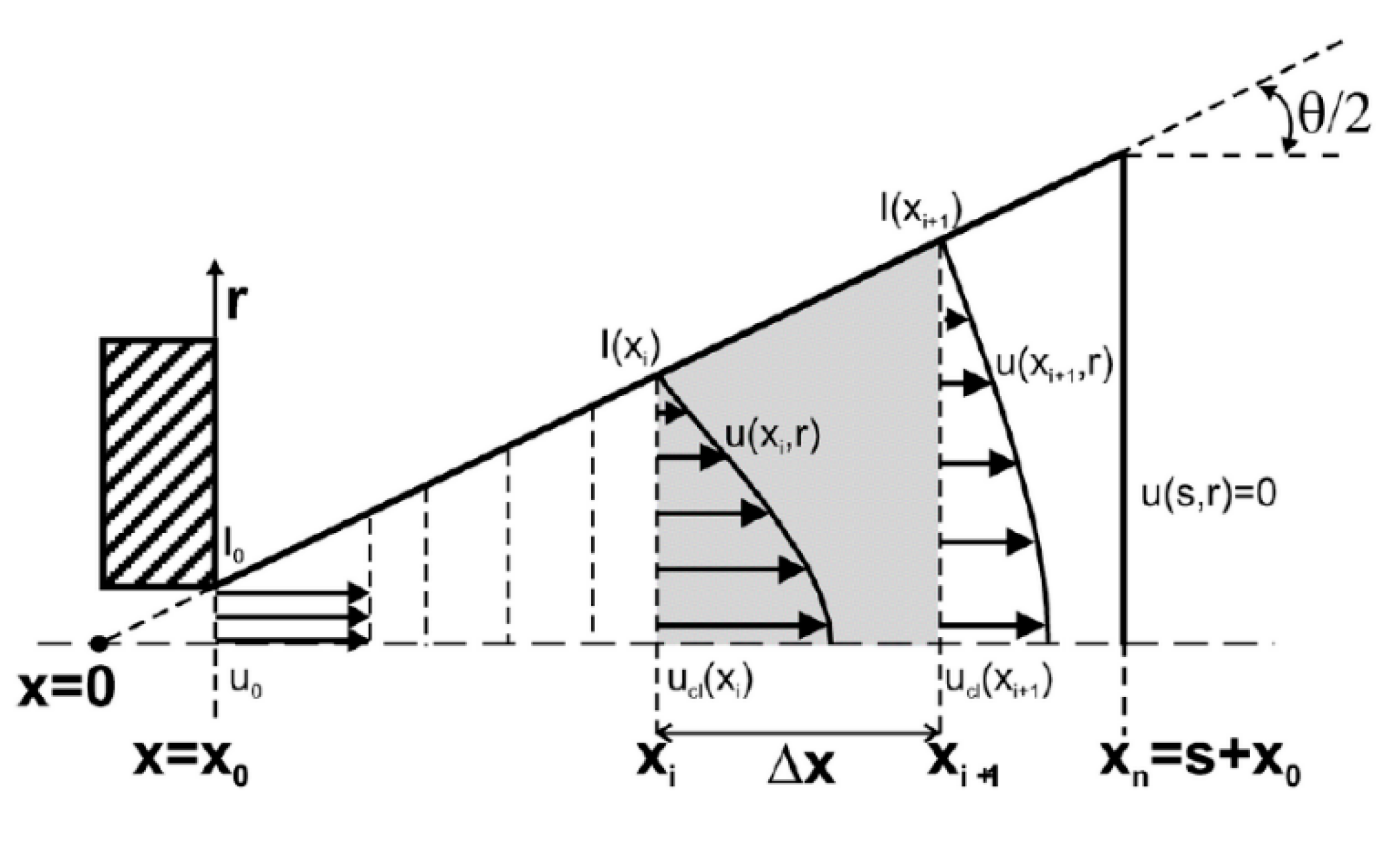
2.2. 1-D Computational Modelling

The analysis of the mixing process has been carried out using a 1D spray model (DICOM), initially developed for diesel-like conditions [22,23]. Assuming that the fuel injection takes place in a large and quiescent volume of air to ensure the no perturbation of the air in spatial positions far away from the spray origin, the model calculates different parameters related to the mixing process of the air and fuel discretizing the domain of the problem as in Figure 1. As shown in the figure, the fuel flow velocity is assumed to be uniform in the region near the injector nozzle. The velocity profile describes a cone angle whose width increases with the axial distance because of the momentum exchange between the fuel and the air. The initial position of the fuel spray is determined as described in Equation (1):
x 0 = d 0 2 · tan ( θ 2 )
where θ/2 and d0 are the spreading angle and nozzle diameter, respectively.
To calculate the different parameters related to the mixing phenomenon, the axial domain of the fuel spray is discretized in cells of thickness Δx, satisfying that xi+1 = xi +Δx, and being i+1 and i and the outlet and inlet sections, respectively.
The model requires the spray cone angle (θ), spray momentum (I0) and mass flux (M0) at the nozzle exit, and the ambient thermodynamic properties from the experiential conditions as inputs. Then, to calculate the instantaneous velocity and mass fractions values of the different species, the model resolves the general conservation equations for the mass of the fuel and the axial momentum in the center line of the spray. To extrapolate the conservative properties radially, self-similar conditions and a radial Gaussian profile are assumed [24]. State relationships are applied to obtain the local temperature, density and composition at each time step. The cell position in which the inlet velocity is non-zero while the outlet velocity is zero is defined as the spray penetration (S). The complete details of the model can be found in [25], while its validation for both single and double injections can be found in [26].
To consider the ambient gas properties in the dual-fuel conditions before the diesel pilot injection [27], the mass fraction of the oxygen at the intake valve closing (IVC) and the stoichiometric air-fuel ratio of the methane-air blend in which the diesel fuel is injected is needed. The last parameter is calculated as shown in Equation (2).
When the charge is composed only by fresh air and natural gas, before the injection of diesel occurs, the addition, as inputs for the model, of the stoichiometric equivalence ratio of the HRF (diesel) and the oxygen mass fraction at the intake valve closing (IVC) is necessary in order to consider the dual-fuel operation [27]. Equation (2) shows the calculation of this stoichiometric equivalence ratio, considering the species existing inside the cylinder when the diesel injection occurs.
ϕ H R F , e s t = 1 ϕ L R F C H R F + H H R F 4 · 12 C H R F + H H R F 32 · 1 1 + Y N 2 , I V C Y O 2 , I V C + ϕ L R F · 1 C L R F + H L R F 4 · 12 C L R F + H L R F 32
where ΦLRF and ΦHRF are the methane (low reactive fuel) and the diesel (high reactive fuel) absolute equivalence ratios—CHRF, CLRF, HHRF and HLRF—designate the number of carbon and hydrogen atoms and YO2,IVC and YN2,IVC stand for the mass fraction of oxygen and nitrogen at the intake valve closing timing, respectively.
The calculations take place from the timing of the start of injection of the pilot diesel fuel (SoIHRF) up to the start of combustion (SoC). The mass distribution at experimental SoC of the high reactivity fuel mixed to different equivalence ratios was obtained after processing the raw results. Figure 2 shows a histogram example of the 1-D model results. For the current case, the bars constitute the high reactivity fuel masses mixed to different local equivalence ratios with their respective envelope curve shown in solid line. To improve clarity, in the present work, only the envelope curve will be shown.

2.3. Test Methodology

The tests have been performed in steady-state operating conditions. To investigate the effects of the main engine control parameters, the diesel injection quantity, premixed ratio, diesel injection pressure and the start of injection of the diesel main injection have been varied. For each of them, three levels have been considered at 1500 and 2000 rpm of engine speed, and partial load 4 and 7 bar of indicated mean effective pressure (IMEP). To isolate the single effect of the parameters investigated, during the parameter sweeps, the boundaries such as boost and back pressure, intake temperature, etc. were all kept constant.
The premixed ratio (rp) is defined as the injected methane mass over the total amount of fuel, (diesel plus methane), and is translated in Equation (3) as
r p [ % ] = m ˙ C H 4   m ˙ C H 4 + m ˙ d i e s e l · 100
where m ˙ C H 4   and m ˙ d i e s e l are the methane and diesel fuel mass flow rates, respectively.
Table 3 shows the levels of the parameter analyzed. For the sake of brevity, the pilot injection and start of injection sweeps have been reported only for 4 bar IMEP, while the premixed ratio (rp) and rail pressure sweeps for 7 bar IMEP. The table reports also the SoC, combustion phasing (CA50), global equivalence ratio and methane equivalence ratio.

3. Results and Discussion

In the following sections, the single effects of the pilot injection quantity, premixed ratio, injection pressure and combustion phasing are discussed.

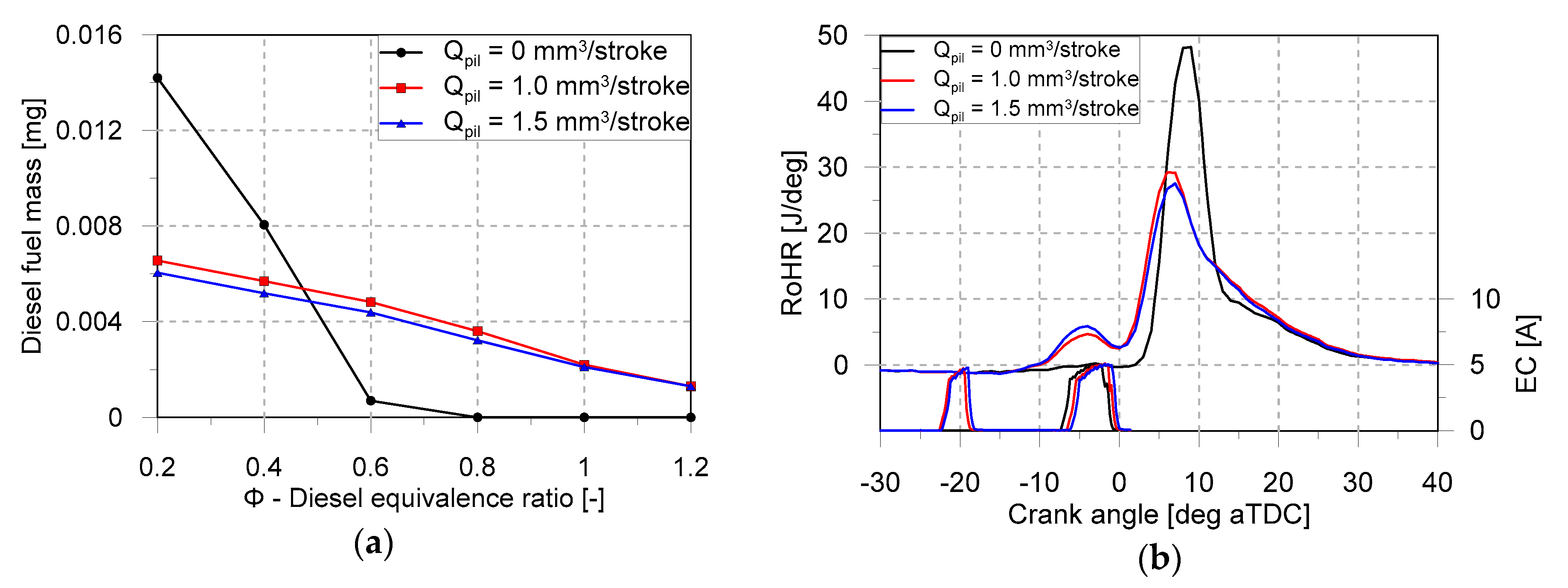
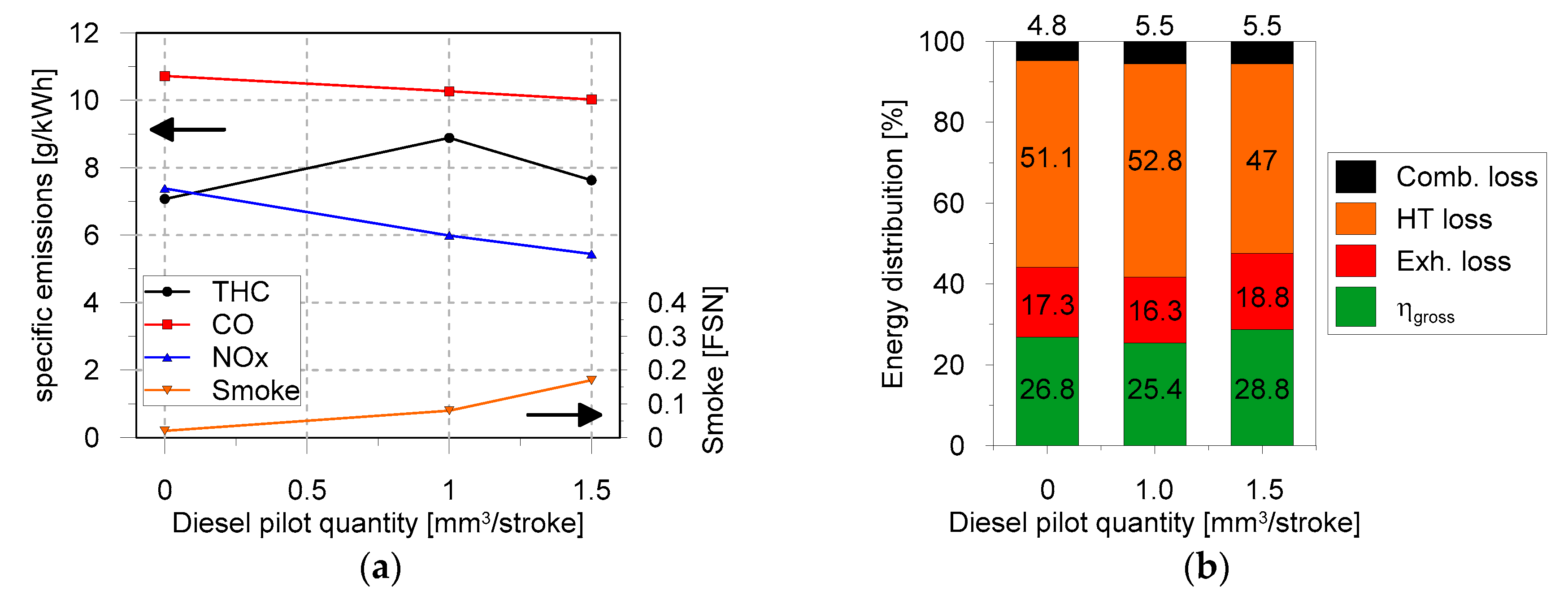
3.1. Pilot Injection Quantity
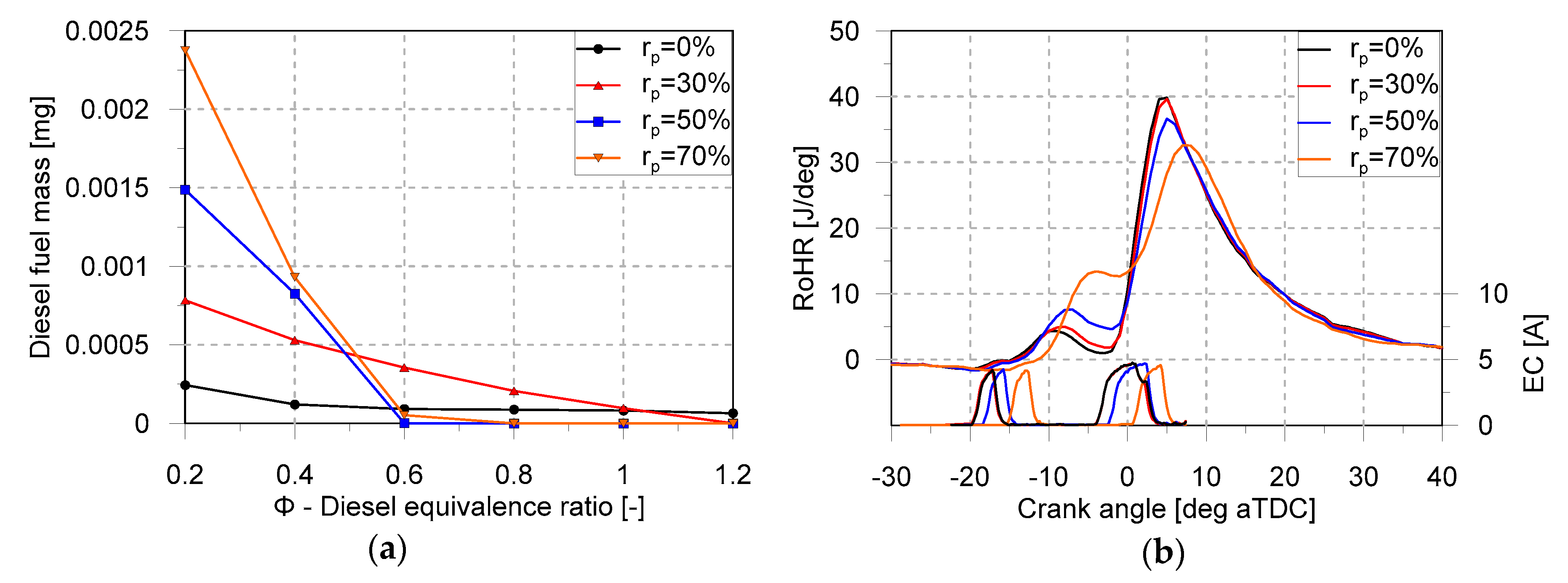
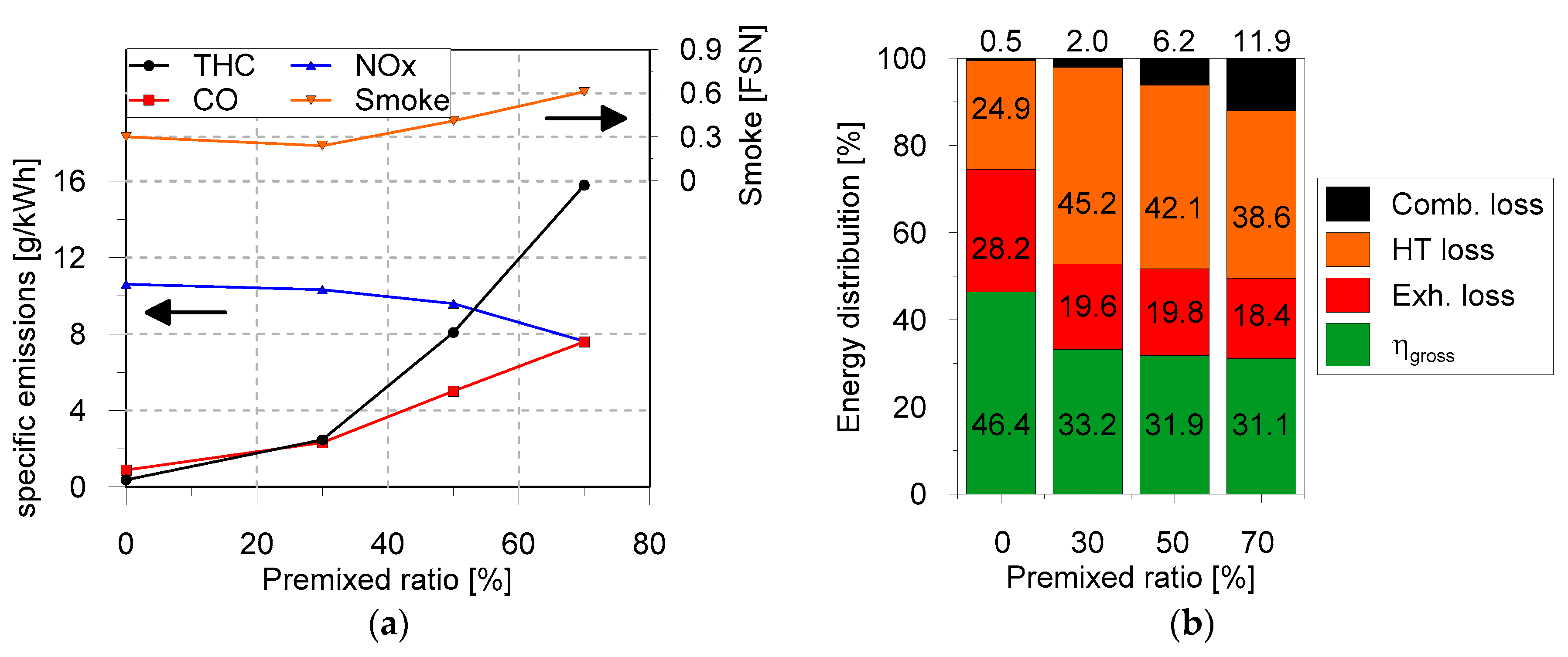
This subsection analyses the pilot injection quantity effect on the combustion process, emissions and efficiencies from the dual-fuel methane-diesel combustion. Three levels of pilot quantity injection were studied with a fixed premixed ratio of 50%. Figure 3 shows the diesel equivalence ratio distribution at the start of combustion (SoC) as well as the rate of heat release (RoHR) for the operating point 2000 × 4. The pilot injection quantities were 0, 1.0 and 1.5 mm3/stroke, keeping constant the total injected quantity (9.1 mm3/stroke). The no pilot condition, that is, 0 mm3/stroke, led to a single peak of heat release and, obviously, to no heat release associated to the pilot injected fuel. This is caused by the more homogeneous in-cylinder distribution achieved at SoC, which results in the simultaneous autoignition of the compressed charge once the proper in-cylinder conditions are reached. Contrarily, the conditions with double injection led to a more stratified Φ distribution at SoC, which promotes more sequential autoignition. Comparing the diesel Φ distribution between the single and double injection strategies (see Figure 3a), it can be noted that the strategy combining double injection events presents richer equivalence ratio distributions. This is a consequence of the shorter mixing time linked to the earlier SoC. The difference between the two strategies with pilot injection is observed in the first and second HR peaks. The case with higher Qpil = 1.5 mm3/stroke leads to slightly higher first HR peak and slightly lower energy availability for the second HR stage.
Figure 4 shows the engine-out emissions and the energy distribution for the operating conditions explored. The smoke level increases with the pilot quantity. It is coherent with the results shown in Figure 3, which suggest a richer equivalence ratio distribution at SoC as the pilot quantity increases. The NOx emissions trend follows the in-cylinder RoHR (or temperature) peaks shown in Figure 3b. The CO emissions slightly reduce with the pilot quantity increase. A reduction of the total hydrocarbon (THC) emissions mainly composed by methane hydrocarbon can be appreciated with Qpil increase from 1.0 mm3/stroke to 1.5 mm3/stroke of pilot injection quantity. However, the THC values are much higher than conventional diesel combustion because in dual-fuel mode, especially at low engine load [28,29], the methane is not completely involved by the combustion flame and this is particularly true for the methane trapped into the crevices volumes [30].
The energy distribution is shown in Figure 4b and calculated by applying the first law of thermodynamics, allows analyzing the heat transfer (HT loss), that is water-oil coolants and radiative losses, and exhaust energy losses (E × h. Loss) compared to the global indicated efficiency (ηgross). The gross indicated efficiency slightly increases passing from the no pilot (0 mm3/stroke) to the double injection (1.5 mm3/stroke) conditions. Indeed, the lower combustion duration reduces the time to transfer heat through the conductive and radiative mechanisms. In the dual-fuel case, the combustion losses slightly increase and range in the interval 5–7% of the total fuel energy, mainly related to the higher THC and CO emissions.

3.2. Premixed Ratio

This subsection analyses the premixed ration effect on the combustion process, emissions and efficiencies from the dual-fuel methane-diesel combustion. Four levels of premixed ration were studied up to 70% including the CDC mode.
The effects of premixed ratio on the combustion evolution, diesel mass Φ distribution (Figure 5), emissions and energy distribution (Figure 6) are discussed. The rp vary from 0 to 70%, keeping constant all the engine control parameters, such as boost, intake temperature, combustion phasing, pilot quantity, etc. During the sweep, at constant engine load, diesel is reduced proportionally to the methane rise. Looking at the RoHR traces (Figure 5b), the conventional diesel combustion shows a higher HTHR peak and a lower first HR peak compared to the dual-fuel operation. This is justified by the reduction of the diesel main quantity substituted by methane, which results in a smoother combustion process, similar to the homogeneous combustion with flame-front propagation of spark-ignited engines.
Looking at the diesel Φ distributions (Figure 5a), among the fuels with different methane percentages, it can be observed that the CDC and dual-fuel with 30% of rp shows a richer Φ distribution compared to dual-fuel with 50% of rp. The main difference between CDC and dual-fuel, from the combustion point of view, can be appreciated analyzing the first and second HR peak. In this sense, the dual-fuel curves show a greater energy release in the first RoHR peak, coming from the pilot HRF burning with the entrained methane. As can be seen, the greater the premixed ratio, the greater the energy released. This can be explained looking at Figure 5a, where the cases with higher rp show more diesel fuel mass mixed in more reactive equivalence ratios. By contrast, the cases with low rp show most of the diesel fuel mass mixed in very lean equivalence ratios. A high amount of heat is released before the TDC, penalizing the thermodynamic efficiency. Looking at the energy distribution chart shown in Figure 6, it can be inferred that by increasing the rp, the gross efficiency decreases. The higher THC and CO emissions penalize the combustion efficiency (up to 10%), and the higher heat release before the top dead center, accentuates the heat transfer losses. The combination of these effects reduces the gross indicated efficiency of about 7% units compared to the CDC mode.
It is worth underlining that the combustion system tested (piston bowl-omega profile, high crevice volume and squish area) properly designed for diesel combustion application, produces a non-optimal fuel-bowl interaction with reduced combustion and thermodynamic efficiencies (Figure 6). This is even more evident at lower engine load conditions [14]. The NOx–Smoke trade-off is consistent with the methane percentage increasing.

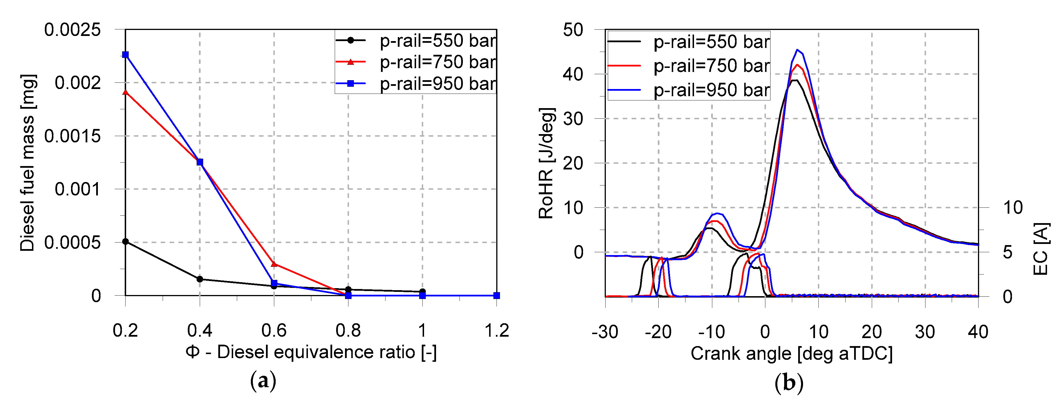
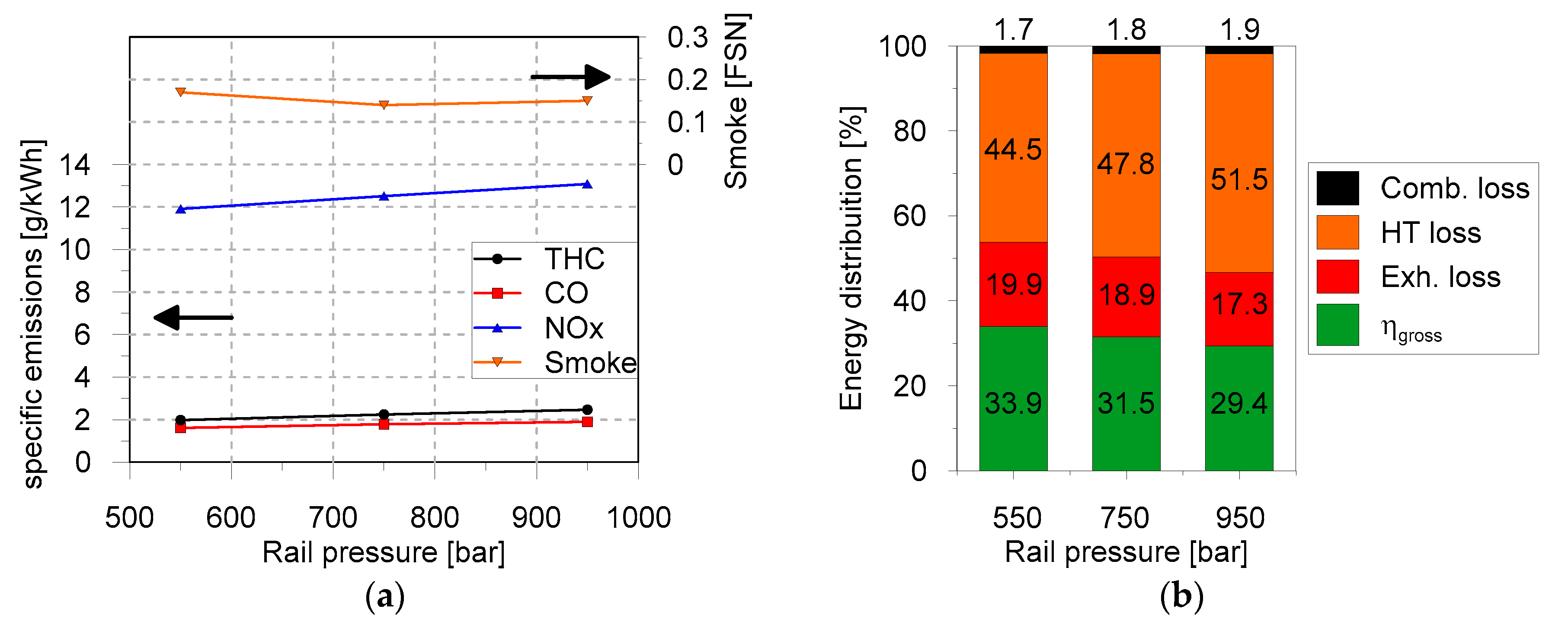
3.3. Injection Pressure

A sensitivity analysis of the effect of the diesel injection pressure on engine response in dual-fuel combustion is discussed. Three levels of injection pressure have been selected starting from the base calibration point (750 bar) and varying this value of ±200 bar. For this analysis, the operating point 1500 × 7 has been considered, fixing the rp to 30%. The injection pressure sweep has been performed at constant diesel pilot quantity (1.5 mm3/stroke), while the diesel main injection quantity has been adapted to achieve the load of 7 bar of IMEP. The combustion phasing was maintained constant and adapted through shifting the injection pattern during the rail pressure sweep.
Looking at the diesel Φ distribution (Figure 7a), with the decrease of the rail pressure a richer Φ distribution can be detected showing the worst minimizing at start of combustion, along with a lower premixed peak, as detectable by the RoHR, due to the longer injection duration of the diesel fuel and the entrained methane into the diesel spray. The trends are in line with the NOx–rail pressure trade-off reported in Figure 8. The smoke emissions are low and almost flat by changing the rail pressure (<0.2 FSN) and this is associated with the higher equivalence ratio. The CO and THC emissions are in the 2–3 g/kWh range, quite high for the tested point and consequence of the non-optimal Φ, injection pattern and combustion system design for the dual-fuel application. Indeed, according to the authors’ experience, this load point represents the lower load limit for operating efficiently the engine in dual-fuel mode [17].
As seen in Figure 8, at lower rail pressure, the gross indicated efficiency improves because the combined improvements of the heat transfer losses and the fuel conversion efficiency prevail on the exhaust gas enthalpy losses. Considering the efficiency values shown in Figure 8b, as found in literature, at low load, the dual-fuel combustion gives lower thermodynamic efficiency than CDC for several reasons such as the not optimized combustion system (bowl, crevices and squish area) and also the low engine load related to the engine application (light-duty).

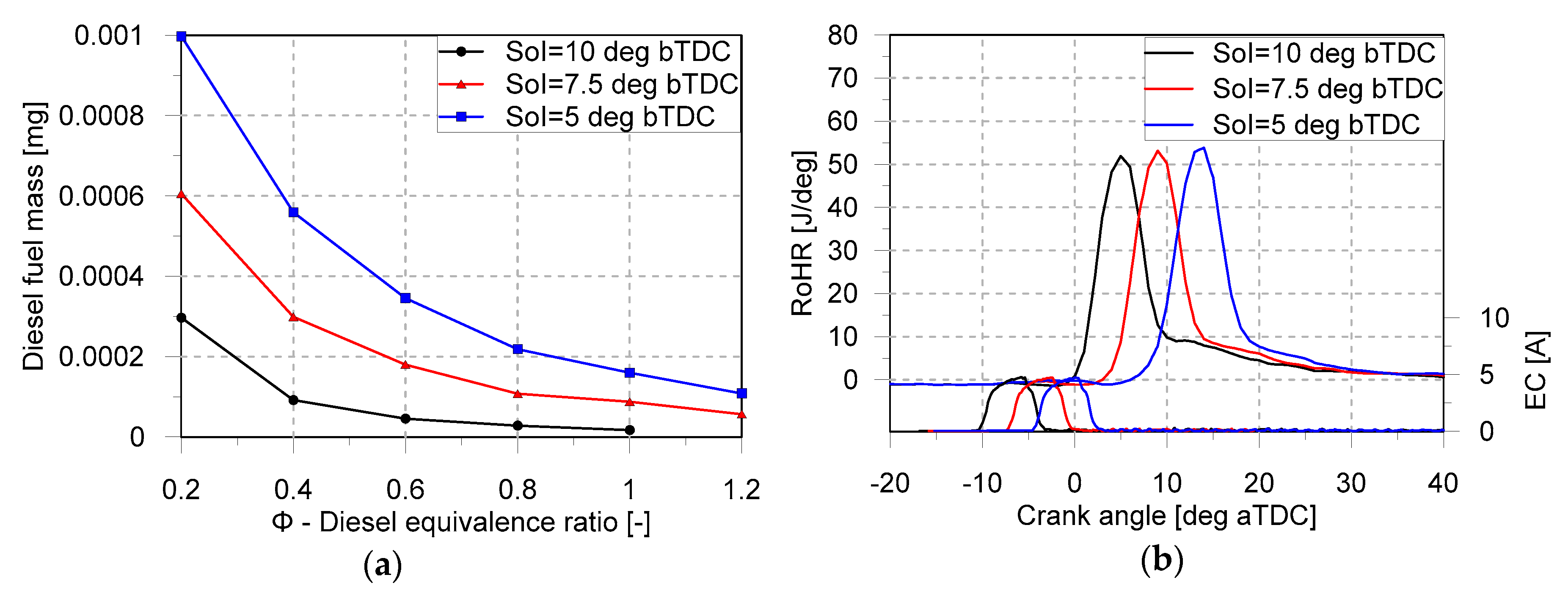
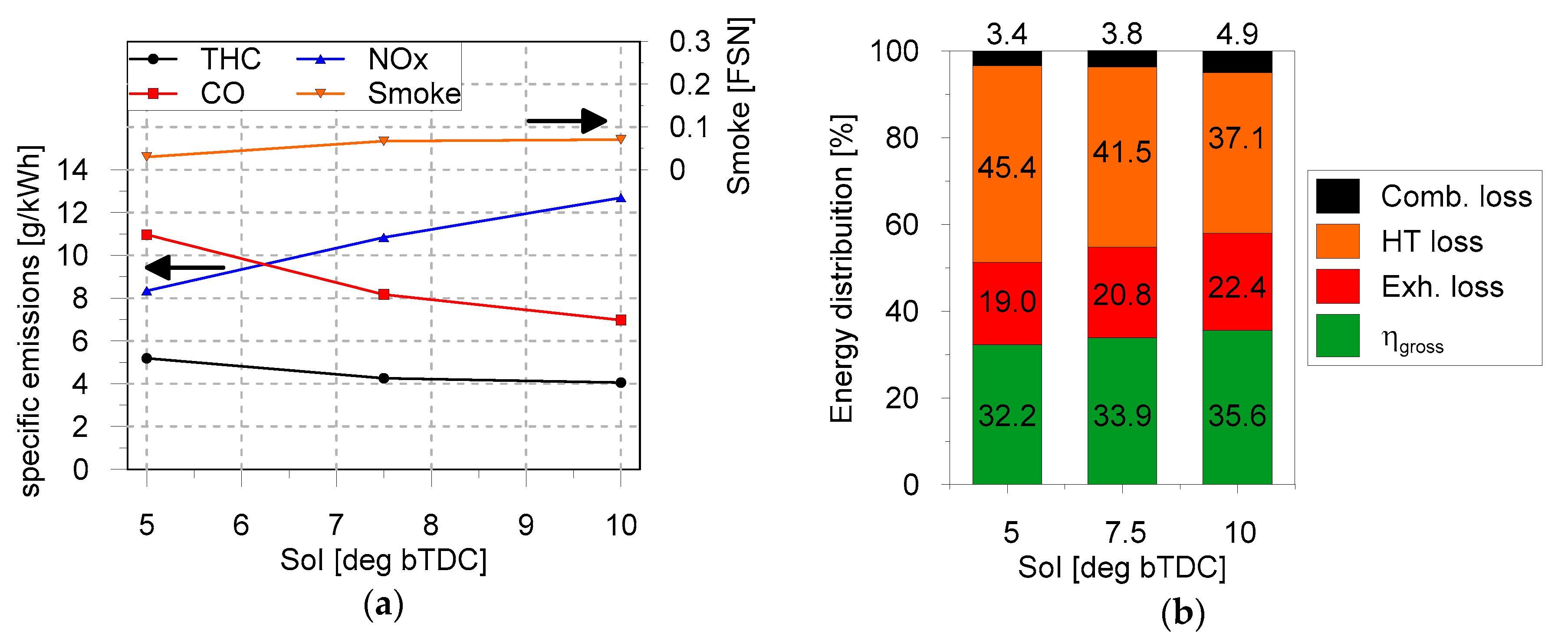
3.4. Combustion Phasing

This section discusses the combustion phasing effects on combustion, emissions, and efficiencies in dual-fuel combustion with 30% of premixed ratio. In this regard, three-levels of the factor start of injection (SoI) have been considered, starting from the reference calibration value, and adopting a variation of ± 2.5 deg around this value. From the combustion point of view, retarding the combustion phasing towards the exhaust phase promotes an increase of the exhaust temperatures (Figure 9) at the expense of reducing the cycle conversion efficiency. Regarding the mixing process, Figure 9 shows a richer equivalence ratio distribution at SoC as the start of injection is delayed.
In terms of engine-out emissions, Figure 10 shows that by advancing the SoI, the NOx level increases about 50% compared to the lowest SoI value. Very low smoke levels (<0.1 FSN) were measured as a combination of the low load conditions (higher air-to-fuel ratio) and dual-fuel mode application. As shown in Figure 10b, the thermodynamic efficiency improves advancing the SoI, which is a consequence of the HT losses reduction. Then, the global efficiency improves about 3.4% comparing the worst (SoI 5 deg) and the best (SoI 10 deg) cases.

4. Conclusions

The current work assesses the influence of the variation of the main injection parameters on the efficiency and emissions of the dual-fuel combustion mode at partial load conditions. In particular, the factors varied are the diesel pilot quantity, diesel injection pressure, the start of diesel injection and the premixed ratio. The indicated traces and emissions are analyzed through an in-house developed 1D model (DICOM), which provides a detailed analysis and additional method to the literature approaches of the air-fuel mixing ratio before the start of combustion. The major findings are summarized as follows:
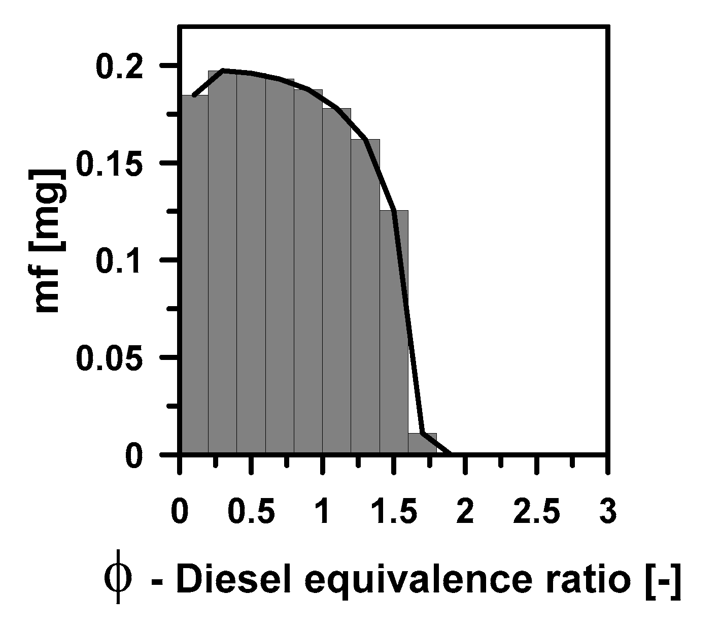
  • At constant engine load, the first HR peak increases as the diesel pilot quantity increases, lowering the available energy for the subsequent HTHR stage. The conventional double pulse injection strategies produce richer equivalence ratio distributions. The gross indicated efficiency slightly increases passing from the no pilot to the double injection.
  • The dual-fuel combustion mode shows higher first HR peak and lower second HR peak than the CDC mode, which results in a smoother combustion process. Regarding the Φ distributions, CDC produces richer Φ distribution compared to the dual-fuel combustion mode. For the points tested, the dual-fuel combustion has a higher heat release before the TDC, penalizing the thermodynamic efficiency. To solve this issue, a recalibration of the injection strategy is recommended.
  • The rail pressure reduction improves the gross indicated efficiency as a consequence of the lower heat release before the TDC, which in turns reduces the heat transfer losses and improves the fuel conversion efficiency. The increase of the rail pressure promotes a richer Φ distribution and a more prominent premixed combustion phase, detectable by the RoHR traces.
  • Delaying the combustion phasing towards the exhaust phase increases the exhaust temperatures at the expense of the cycle conversion efficiency. Then, advancing the combustion phasing promotes richer equivalence ratio distributions at SoC.
The results of this research evidence that in dual-fuel combustion mode at low load, the first HR peak strongly affects the efficiency and emissions. By adjusting the injection parameters, such as pilot quantity, methane percentage, diesel injection pressure and the start of injection, an improvement of the gross indicated efficiency from 2% to 3.5% can be achieved. The adopted methodology and the consequent experimental findings can further improve the application of advanced combustion strategies and greener fuels.

Author Contributions

J.M.-S.: Conceptualization, writing—review and editing; G.B.: Data curation, writing—original draft; G.D.B.: Supervision, validation; M.G.-M.: Software, writing—review and editing. All authors have read and agreed to the published version of the manuscript.

Funding

This research was partially funded by FEDER and SPANISH MINISTERIO DE ECONOMÍA Y COMPETITIVIDAD through Tranco project, grant number TRA2017-87694-R. The authors also acknowledge the UNIVERSITAT POLITÈCNICA DE VALÈNCIA for partially funding this research through Convocatoria de Ayudas a Primeros Proyectos de Investigación, grant number PAID-06-18.

Conflicts of Interest

The authors declare no conflict of interest. The funders had no role in the design of the study; in the collection, analyses, or interpretation of data; in the writing of the manuscript, or in the decision to publish the results.

References

  1. The European Commission Regulatory Proposal for Post-2020 CO2 Targets for Cars and Vans. Available online: https://www.theicct.org/publications/ec-proposal-post-2020-co2-targets-briefing-20180109 (accessed on 22 March 2020).
  2. Proposal for Post-2020 CO2 Targets for Cars and Vans. Available online: https://ec.europa.eu/clima/policies/transport/vehicles/proposal_en (accessed on 22 March 2020).
  3. Kobashi, Y.; Wang, Y.; Shibata, G.; Ogawa, H.; Naganuma, K. Ignition control in a gasoline compression ignition engine with ozone addition combined with a two-stage direct-injection strategy. Fuel 2019, 2491, 154–160. [Google Scholar] [CrossRef]
  4. Shim, E.; Park, H.; Bae, C. Comparisons of advanced combustion technologies (HCCI, PCCI, and dual-fuel PCCI) on engine performance and emission characteristics in a heavy-duty diesel engine. Fuel 2020, 26215, 116436. [Google Scholar] [CrossRef]
  5. Jafari, H.; Yang, W.; Ryu, C. Evaluation of a distributed combustion concept using 1-D modeling for pressurized oxy-combustion system with low flue gas recirculation. Fuel 2020, 2631, 116723. [Google Scholar] [CrossRef]
  6. Gohn, J.; Gainey, B.; Zainul, S.; Lawler, B. Wet ethanol in LTC: How water fraction and DTBP affect combustion and intake temperature at naturally aspirated and boosted conditions. Fuel 2020, 2671, 117094. [Google Scholar] [CrossRef]
  7. Belgiorno, G.; Di Blasio, G.; Shamun, S.; Beatrice, C.; Tunestål, P.; Tunér, M. Performance and emissions of diesel-gasoline-ethanol blends in a light duty compression ignition engine. Fuel 2018, 217, 78–90. [Google Scholar] [CrossRef]
  8. Benajes, J.; Pastor, J.V.; García, A.; Monsalve-Serrano, J. The potential of RCCI concept to meet EURO VI NOx limitation and ultra-low soot emissions in a heavy-duty engine over the whole engine map. Fuel 2015, 159, 952–961. [Google Scholar] [CrossRef]
  9. Tripathi, G.; Sharma, P.; Dhar, A. Effect of methane augmentation on combustion stability and unregulated emissions in compression ignition engine. Fuel 2020, 2631, 116672. [Google Scholar] [CrossRef]
  10. Calam, A.; Aydoğan, B.; Halis, S. The comparison of combustion, engine performance and emission characteristics of ethanol, methanol, fuel oil, butanol, isopropanol and naphtha with n-heptane blends on HCCI engine. Fuel 2020, 2615, 117071. [Google Scholar] [CrossRef]
  11. Benajes, J.; García, A.; Monsalve-Serrano, J.; Villalta, D. Benefits of E85 versus gasoline as low reactivity fuel for an automotive diesel engine operating in reactivity controlled compression ignition combustion mode. Energy Convers. Manag. 2018, 159, 85–95. [Google Scholar] [CrossRef]
  12. Srna, A.; von Rotz, B.; Herrmann, K.; Boulouchos, K.; Bruneaux, G. Experimental investigation of pilot-fuel combustion in dual-fuel engines, Part 1: Thermodynamic analysis of combustion phenomena. Fuel 2019, 2551, 115642. [Google Scholar] [CrossRef]
  13. Srna, A.; von Rotz, B.; Bolla, M.; Wright, Y.; Herrmann, K.; Boulouchos, K.; Bruneaux, G. Experimental investigation of pilot-fuel combustion in dual-fuel engines, Part 2: Understanding the underlying mechanisms by means of optical diagnostics. Fuel 2019, 2551, 115766. [Google Scholar] [CrossRef]
  14. Di Blasio, G.; Belgiorno, G.; Beatrice, C.; Fraioli, V. Experimental Evaluation of Compression Ratio Influence on the Performance of a Dual-Fuel Methane-Diesel Light-Duty Engine. SAE Int. J. Engines 2015, 8, 2253–2267. [Google Scholar] [CrossRef]
  15. Yousefi, A.; Guo, H.; Birouk, M. Effect of diesel injection timing on the combustion of natural gas/diesel dual-fuel engine at low-high load and low-high speed conditions. Fuel 2019, 2351, 838–846. [Google Scholar] [CrossRef]
  16. Wang, L.; Chen, Z.; Zhang, T.; Zeng, K. Effect of excess air/fuel ratio and methanol addition on the performance, emissions, and combustion characteristics of a natural gas/methanol dual-fuel engine. Fuel 2019, 2551, 115799. [Google Scholar] [CrossRef]
  17. Belgiorno, G.; Di Blasio, G.; Beatrice, C. Parametric study and optimization of the main engine calibration parameters and compression ratio of a methane-diesel Dual Fuel engine. Fuel 2018, 222, 821–840. [Google Scholar] [CrossRef]
  18. Belgiorno, G.; Di Blasio, G.; Beatrice, C. Advances of the Natural Gas/Diesel RCCI Concept Application for Light-Duty Engines: Comprehensive Analysis of the Influence of the Design and Calibration Parameters on Performance and Emissions. In Natural Gas Engines; Springer: Singapore, 2019; pp. 251–266. [Google Scholar]
  19. Rochussen, J.; Yeo, J.; Kirchen, P. Effect of Fueling Control Parameters on Combustion and Emissions Characteristics of Diesel-Ignited Methane Dual-Fuel Combustion; SAE Technical Paper 2016-01-0792; SAE International: Warrendale, PA, USA, 5 April 2016. [Google Scholar]
  20. Papagiannakis, R.G.; Hountalas, D.T. Experimental investigation concerning the effect of natural gas percentage on performance and emissions of a DI dual fuel diesel engine. Appl. Therm. Eng. 2003, 3, 353–365. [Google Scholar] [CrossRef]
  21. Heywood, J. Internal Combustion Engine Fundamentals; McGraw-Hill: New York, NY, USA, 1988; ISBN 0-07-100499-8. [Google Scholar]
  22. Pastor, J.V.; López, J.J.; García, J.M.; Pastor, J.M. A 1D model for the description of mixing-controlled inert diesel sprays. Fuel 2008, 87, 2871–2885. [Google Scholar] [CrossRef]
  23. Desantes, J.M.; Pastor, J.V.; García-Oliver, J.M.; Pastor, J.M. A 1D model for the description of mixing-controlled reacting diesel sprays. Combust. Flame 2009, 156, 234–249. [Google Scholar] [CrossRef]
  24. Pastor, J.V.; García-Oliver, J.M.; Pastor, J.M.; Vera-Tudela, W. One-dimensional diesel spray modeling of multicomponent fuels. At. Sprays 2015, 25, 485–517. [Google Scholar] [CrossRef]
  25. Garcia, A.; Monsalve-Serrano, J.; Heuser, B.; Jakob, M.; Kremer, F.; Pischinger, S. Influence of fuel properties on fundamental spray characteristics and soot emissions using different tailor-made fuels from biomass. Energy Convers. Manag. 2016, 108, 243–254. [Google Scholar] [CrossRef] [Green Version]
  26. Pastor, J.V.; Payri, R.; García-Oliver, J.M.; Briceño, F.J. Analysis of transient liquid and vapor phase penetration for diesel sprays under variable injection conditions. At. Sprays 2011, 21, 503–520. [Google Scholar] [CrossRef]
  27. Benajes, J.; Molina, S.; García, A.; Monsalve-Serrano, J. Effects of Direct injection timing and Blending Ratio on RCCI combustion with different Low Reactivity Fuels. Energy Convers. Manag. 2015, 99, 193–209. [Google Scholar] [CrossRef]
  28. Di Blasio, G.; Belgiorno, G.; Beatrice, C. Effects on performances, emissions and particle size distributions of a Dual Fuel (methane-diesel) light-duty engine varying the compression ratio. Appl. Energy 2017, 204, 726–740. [Google Scholar] [CrossRef]
  29. Ryu, K. Effects of pilot injection timing on the combustion and emissions characteristics in a diesel engine using biodiesel–CNG dual fuel. Appl. Energy 2013, 111, 721–730. [Google Scholar] [CrossRef]
  30. Di Blasio, G.; Belgiorno, G.; Beatrice, C. Parametric Analysis of Compression Ratio Variation Effects on Thermodynamic, Gaseous Pollutant and Particle Emissions of a Dual-Fuel CH4-Diesel Light Duty Engine; SAE Technical Paper; SAE International: Warrendale, PA, USA, 28 March 2017. [Google Scholar]
Figure 1. Model description.
Energies 13 03734 g001
Figure 2. Diesel mass quantity mixed at different Φ at the start of combustion timing.
Energies 13 03734 g002
Figure 3. Diesel mass under the local equivalence ratio at the start of combustion (a) and rate of heat release (RoHR) (b) for two different diesel pilot quantities at 2000 × 4 and 50% of premixed ratio.
Energies 13 03734 g003
Figure 4. Engine-out emissions (a) and energy distribution (b) for different diesel pilot quantities at 2000 × 4 with 50% of premixed ratio.
Energies 13 03734 g004
Figure 5. Diesel mass under the local Φ at the start of combustion (a) and RoHR (b) for different premixed ratios at 2000 × 7.
Energies 13 03734 g005
Figure 6. Engine-out emissions (a) and energy distribution (b) for different premixed ratios at 2000 × 7.
Energies 13 03734 g006
Figure 7. Diesel mass under the local equivalence ratio at the start of combustion (a) and RoHR (b) for different levels of rail pressure at 1500 × 7 and 30% premixed ratio.
Energies 13 03734 g007
Figure 8. Engine-out emissions (a) and energy distribution (b) for different levels of rail pressure at 1500 × 7 and 30% premixed ratio.
Energies 13 03734 g008
Figure 9. Diesel mass under the local equivalence ratio at the start of combustion (a) and RoHR (b) for different levels of the start of injection at 2000 × 4 and 30% of premixed ratio.
Energies 13 03734 g009
Figure 10. Engine-out emissions (a) and energy distribution (b) for different levels of rail pressure in at 2000 × 4 and 30% premixed ratio.
Energies 13 03734 g010
Table 1. Main engine geometrical characteristics.
ParameterValue
Displaced volume477.5 cm3
Stroke90 mm
Bore82 mm
Compression ratio16.5
Number of Valves4
Diesel Injection SystemCommon rail
Diesel InjectorSolenoid 7 holes
PFI InjectorMultihole
Table 2. Fuel properties.
FeatureEN590 DieselMethane
Density [kg/m3] STP8400.788
Autoignition temperature [°C]300595
Cetane Number53-
Octane Number->120
LHV [MJ/kg]42.9549.5
AFRstoich [-]14.717.2
H/C [-]~1.864
Table 3. Level of operating parameters investigated for the two engine part loads tested.
ParametersEngine Speed × IMEP
[rpm] × [bar]
2000 × 41500 × 72000 × 7
Qpil [mm3/stroke]0 - 1.0 - 1.51.51.5
rp [%]50300 - 30 - 50 - 70
p-rail [bar]630550 - 750 - 950910
SoI [deg bTDC]5.0 - 7.5 – 10.07.3 - 5.3 - 4.34.0 – 4.0 – 3.0 – 0.0
SoC [deg aTDC]6.3 - 3.2 - 3.31.6 - 2.4 - 2.51-8 - 1.9 - 0.3 - -2.2
CA50 [deg aTDC]9.59.39.1
Global equivalence ratio [-]0.500.670.44 - 0.65 - 0.69 - 0.73
Methane equivalence ratio [-]0.150.230 - 0.25 - 0.38 - 0.55

