
On the Use of Robust Techniques in Smart Grid Control


DIEI–Dipartimento di Ingegneria Elettrica e dell’Informazione, Università degli Studi di Cassino e del Lazio Meridionale, 03043 Cassino, Italy
Energies 2022, 15(1), 7; https://doi.org/10.3390/en15010007
Submission received: 4 November 2021
/
Revised: 7 December 2021
/
Accepted: 15 December 2021
/
Published: 21 December 2021
(This article belongs to the Collection Feature Papers in Smart Grids and Microgrids)
Abstract
:This paper discusses the application of robust control techniques to a smart grid (SG) in order to find more powerful and suitable control tools to guarantee SG robustness. Two key aspects are in particular discussed. The first one relates to the need of a suitably model for the SG. The second one relates to the selection of an appropriate robust control technique to guarantee rejection of the adverse effects caused by mutual interactions among control loops and model uncertainty. The final purpose is to bridge the gap between the power of robust control theorems and the reality of SG operations.
1. Introduction
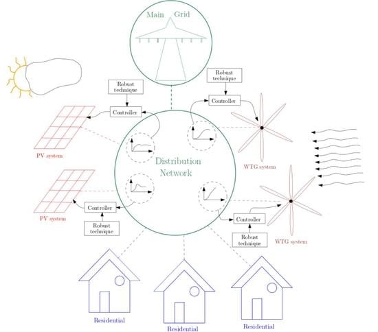
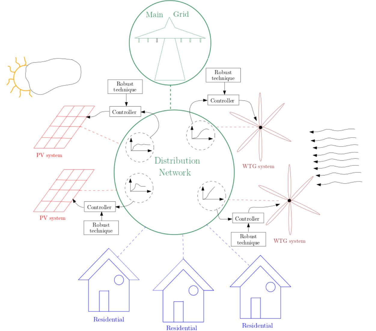
A Smart Grid (SG) is an intelligent electrical network designed to handle the presence of Renewable Energy Sources (RESs) using information and communication technology employing smart meters and control systems. It is unquestionable that the primary mission of an RES is to transfer the active power to the SG. In addition, the presence of RESs reduces greenhouse gas emissions and decreases the power losses of the transmission and distribution systems. From this perspective, the main challenge is how to provide sound support for effectively integrating larger penetration of RESs by ensuring specific control properties such as robustness, and at the same time, limiting the well-known negative impact of RESs on the SGs [1,2]. A robust control system is insensitive to differences between the real system and its model employed in the controller’s synthesis. These differences represent the uncertainty that is described by appropriate models. In the context of SG control, changes in the operating conditions with respect to the nominal one used in the design are represented by uncertainty affecting the model of an SG. Operating condition variations arise in the presence of, for example, changes in active and/or reactive powers output by RESs caused by the variable nature of wind speed and solar irradiance, connection and/or disconnection of loads, etc. All these conditions are referred to as normal operating conditions. Hence, a robust controller guarantees smooth operations of an SG under a wide range of different normal operating points. Conversely, the presence of faults or short circuits cannot be referred to as normal operating conditions. This paper does not consider the presence of faults or short circuits in SG.
From this point of view, the control of SG is becoming much more important in accordance with increasing size, increasing diversity in generation/load, variable nature of the primary source as in the case of solar and wind generation units, uncertainties in the system model of SG, and different types of RESs.
In this new paradigm, classical control techniques may not be more adopted in controlling a SG. In fact, it is difficult to guarantee robustness in the presence of model uncertainty and interactions among control loops using classical control strategies [3]. This suggests considering advanced control approaches, such as the robust control theory. Robust control techniques due to the possibility of uncertainties formulation in the control synthesis guarantee stability under different unknown scenarios of the SG.
Robust control methods such as , structured singular value , model predictive control (MPC), backstepping control, real stability radius , and condition based on the largest singular value of the perturbed model, are well suited to applications where uncertainty is present. Once the controller is designed, its parameters do not change and robustness is guaranteed in the presence of a wide range of disturbances and uncertainties.
The choice of a suitable robust control technique represents a key aspect in the synthesis of control systems for complicated processes. This choice depends on some items such as type of control problem, control objectives, model of the uncertainty, and model of the process.
However, the application of the robust control to SG is not straightforward and it has been the subject of an increasing amount of research in the last years. The problem to guarantee robustness under uncertainty and disturbances in the system model can be tackled using different techniques. Paper [4] uses a robust optimization framework in which the control problem is formulated as a mixed-integer linear programming with uncertain data. Paper [5] employs the real stability radius to find the largest perturbation that makes the closed loop uncertain system unstable. Paper [6] decomposes the overall system according to the H-Δ model technique [7]. Paper [8] develops a robust control design based on the theorem reported in [9]. Papers [10,11] present the design of a robust controller according to the Model Predictive Control (MPC) based approach. Papers [12,13] employ the control theory while paper [14] uses the Quantitative Feedback Theory (QFT). Paper [15] develops a robust nonlinear partial feedback linearizing control law.
To design a robust controller it is important to deal with two main aspects. The first one concerns the need of obtaining an overall model of the SG which embeds the models of RES, Distribution Network (DN), uncertainty and disturbances. The second one concerns the objective of adopting a suitable robust control technique that leads both to a simple design and to a controller with low-order, which represents an useful requirement for its practical implementation. The discussion reported in this paper aims at illustrating the key aspects related to these two challenges and to present possible models and solutions.
2. Smart Grid Models
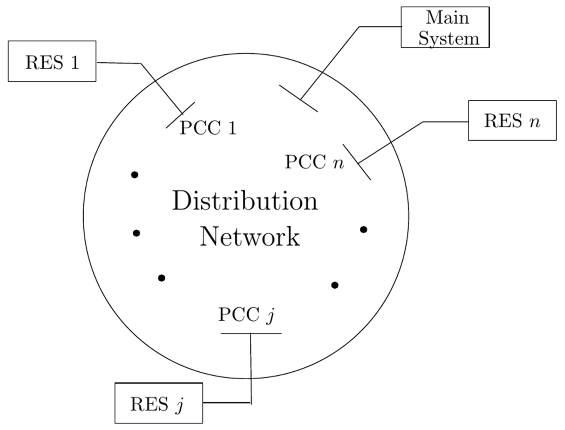
In the synthesis procedure of a robust control technique, the dynamic model of a SG is required. Obtaining this model is not simple, mainly due to extension of the DN and to the type of RES. However understanding these models allows the application of robust design methods that are familiar to the control system community. It is unquestionable that the model to adopting is strictly related to the control objectives. Since integration of RESs into utilities’ networks can cause undesirable effects on voltage control caused by the reverse power flows along the feeders, the models of an SG aim at expressing the relationships between the voltage variations and the active and reactive powers injections at the Points of Common Coupling (PCC); see Figure 1, where the RESs are connected to the DN.
Different is the case of a Micro Grid (MG). The MG is a small-size network hosting a small number of RESs that can be connected or disconnected (islanded-mode) to the main grid. In the former case, the control is more simple than the islanding mode, because voltage and frequency control of an MG is guaranteed by the main grid. The real and reactive power of a RES unit are controlled by acting on the Voltage Source Converter (VSC) output voltage in order to maintain an equilibrium between the power generated and the load power demand while ensuring that voltage and frequency are within their respective range.
The types of RES can be divided into two categories: the first one groups plants using renewable energy sources such as wind turbines and solar power plants; conversely, the second one groups plants using fossil fuels such as conventional combined heat and power (CHP) generators. RESs using renewable energy sources are typically interfaced to the DN by VSCs and possibly integrated with a battery. Such a configuration is the most widely adopted in practicem especially for small-size RESs [16].
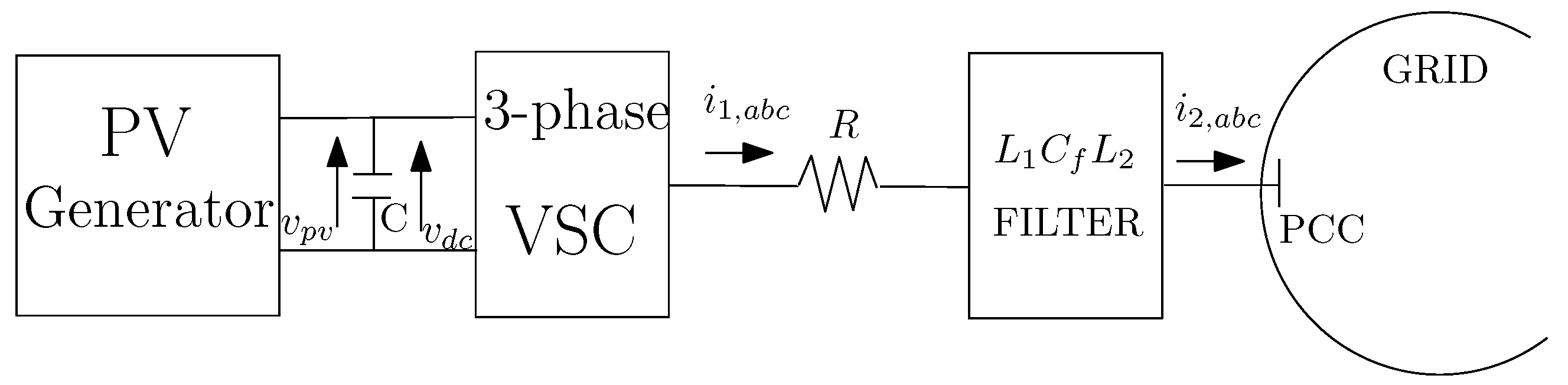
In the case of a PV system, Figure 2 shows a schematic representation of a single-stage PV system connected to the grid. The PV system mainly consists of a PV array, a 3-phase VSC and a filter.
Models of different order can be found in the literature to express the dynamic of a PV system, see among them [12,15,17]. Usually such models are represented in the space-state. A general nonlinear state-space model expressed in frame is the following [17]
where R is the resistance, , , and inductances and capacitance of the filter, is the voltage of the dc-link capacitor, the voltage of the filter capacitor, and output currents of the inverter and filter, respectively, the angular frequency, the output current of the inverter, and are the switching input signal to the inverter and v the voltage across the PCC node. The subscript f stands for filter.
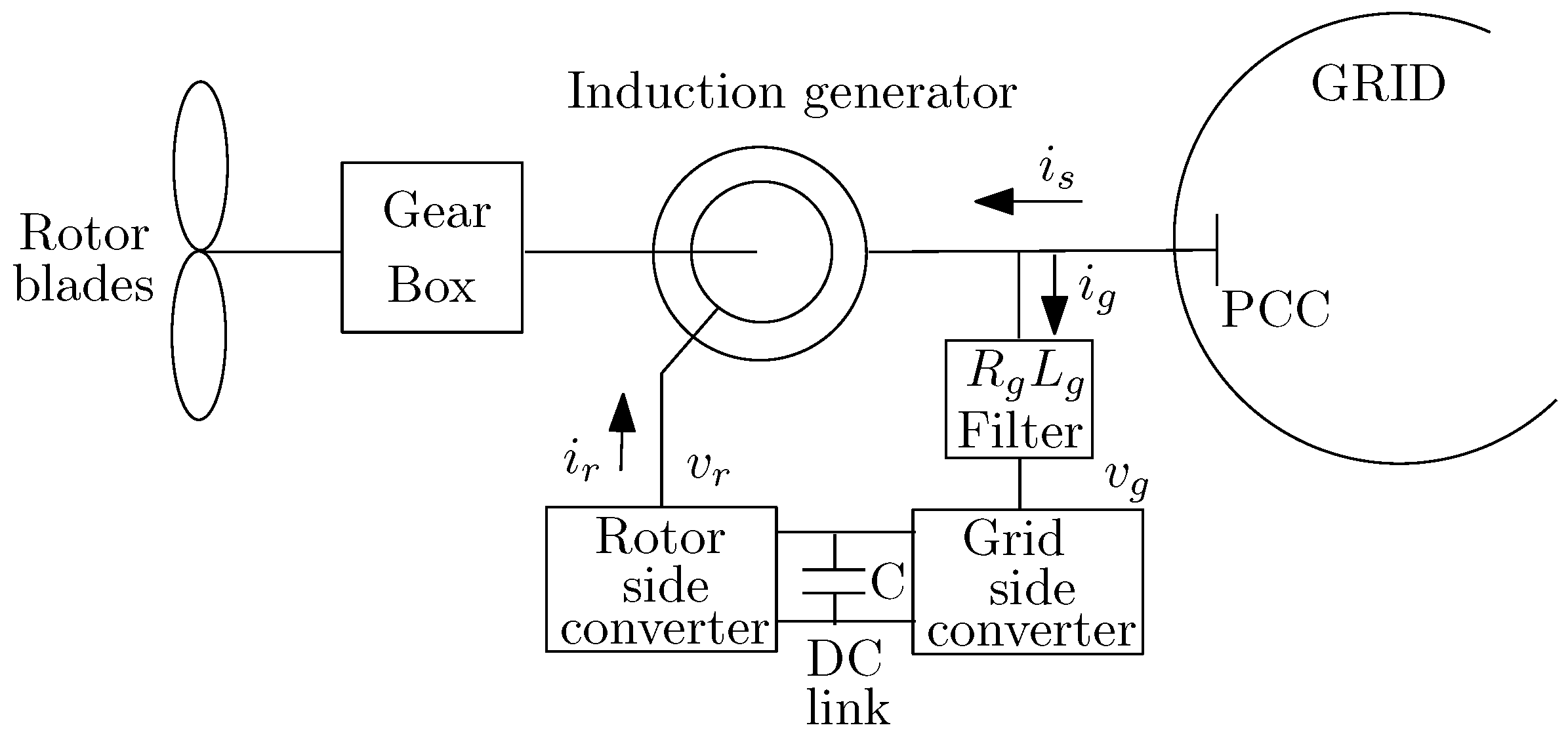
In the case of a wind turbine generator (WTG), Figure 3 shows a schematic block scheme representation. It mainly consists of a gear box, an induction generator, a rotor side converter, a grid-side converter, and a filter. A general model is derived in [18] and is reported in the following.
In particular the first two equations model the mechanical components of the WTG. The subsequent five equations model the WTG; the eighth equation models the grid-side filter. Moreover, is the torque, , v and i are flux, voltage, and current, respectively, subscripts s, r stand for stator and rotor quantities, and denote the inertia constants of the induction generator and turbine; D represents the damping coefficient; and are the shaft angle and stiffness of the shaft, respectively. Symbol L represents the inductance, is the rotor pulse, the angular pulse and is the speed of the frame. Moreover symbol R represents the resistance. Subscript g stands for filter variables, , and are the components of the generator voltage, grid-side filter current and voltage, respectively. is the voltage of the gride-side converter.
Concerning the loads, they can usually be considered static and then represented by an equivalent parallel RLC impedance. Concerning the lines, they are represented by lumped series elements. Eventually the main system is modeled by an ac voltage source in series with a resistance R and an inductance L.
The described dynamic models can be linearized in a given operating condition and expressed in compact form in the state-space as follows
where is the state vector, is the control input, is the controlled output, is the measured output, and is the disturbance input.
Equations (1)–(3) represents a suitable model for the application of robust control techniques in the MG control synthesis. However in presence of a large number of RESs, the dimension of model (1)–(3) becomes of high order. For this reason, model (1)–(3) is mainly used in the control of MG since the RESs number of a MG is much smaller than that of a SG.
In the case of a SG with high penetration of RESs, the approach used to model the dependency of voltages on the active and reactive power changes employs the sensitivity analysis approach [4,19,20]. This technique uses the inverse of the Jacobian matrix obtained from the solution of a power flow study. Another approach is known as perturb-and-observe. It solves multiple power flows in which small changes in the RES active and/or reactive power outputs are imposed and, subsequently, extracts the corresponding sensitivity’s coefficients [21].
Starting from a given operating condition of the DN, a linear model gives the sensitivity coefficients matrix, which expresses the variations of the nodal voltages caused by variations of the active and reactive powers injected by all RESs. According to [22], the linearized model can be written as
where N is the number of the nodes, the number of RESs, is the squared voltage of the ith network node; is the (initial) value of obtained in absence of RESs; , are the powers (respectively, active and reactive) output by an RES; is a vector of sensitivity coefficients that linearly relates the squared voltage at the i-th node to the powers , .
Concerning the model of an RES, a TITO (Two-Inputs Two Outputs) model can be adopted. The inputs are the currents reference output by the local controller while the outputs are the active and reactive powers injected by the RES into the grid. The reference currents are expressed in the reference frame obtained by a PLL, which imposes that the currents independently control, respectively, active and reactive powers [23]. However, since the PLL shows a short time response, and due to the presence of the filter, the dynamic of the two current components are coupled. The general form of the th RES model is [24,25]
where and are the reference currents in the frame and is given by
The diagonal elements model the dynamics along the d and q axes, respectively, while the off-diagonal elements model the cross-coupling dynamics.
Substituting (5) into (4) for each RES, the general Multi-Input Multi-Output (MIMO) model of an SG can be expressed compact form as
where is the K vector of the squared voltages at the PCCs, is the value of , is the matrix composed of vectors , and is the vector of inputs and . The dimension of the square plant matrix is .
3. Robust Control Techniques in Smart Grid
In the SG control, it is usually desirable to meet reference tracking and to limit adverse effects caused by both interactions among control loops and uncertainty in the system model. Such undesirable effects may lead to performance degradation and to instability [26,27,28]. In addition, the non perfect knowledge of the line parameters of the SG represents a source of uncertainty [24,29].
It should be emphasized that operating point variations of an SG are commonly represented as uncertainty in the system model. Since robust control techniques are able to reject the effects of model uncertainty, the design of the controller is not based on the assumption of complete knowledge of the actual operating condition of the grid. It means that load demand and generated power are not known.
To guarantee fulfillment of the control objectives previously described, it is then advisable, on one hand to reduce the loops interactions, and on the other hand to adopt robust control techniques to reject the effects of bounded disturbances and model uncertainty. In fact, unlike conventional controllers, robust controllers are capable of capturing the design objectives, thus ensuring robust stability in all operating conditions of the grid.
In SG control, the parametric perturbations are lumped into a perturbation matrix . This uncertainty representation is known as unstructured uncertainty. Concerning uncertainty, there are different models to express the most representative unstructured uncertainty [30]; such models are: additive
input multiplicative
output multiplicative
where is the nominal plant, represents the uncertainty with .
It must be pointed out that the problem to limit the negative effects caused by interactions among control loops has to be tackled also in the absence of system uncertainty (nominal plant). However, it is well known that robust stability also guarantees nominal stability.
The problem of the mutual couplings among control loops has been studied in [27]. In particular in this paper, using the Block Gerschgorin theorem, it is shown that the infinity norm of off-diagonal transfer functions of matrix equals to the norm of their coupling variables. Recalling that off-diagonal elements model the coupling between the i-th RES and other RESs, the paper has given a metric to weight the interactions. To reduce the effects of the interactions, some approaches have been proposed in the literature. In [14,31,32] the Relative Gain Array (RGA) matrix is employed to determine the best input and output pairs. Subsequently, pre-compensator and post-compensator are designed to make the whole system approximately diagonal so that the overall control can be realized by an independent (decentralized) design of any controller. However the application of the RGA method might present difficulty in SG with high penetration of RESs. In fact, the dimension of the RGA matrix increases as the number of RESs grows. Techniques based on the use of RGA matrix guarantee negligible mutual interactions among control loops if the elements of the RGA are approximately equal to one. Hence, in the case of an SG with a large penetration of RESs, it becomes quite difficult to obtain negligible interactions. Aside from the use of RGA, the decoupling compensator has the same order of complexity of the controlled plant. Moreover, exact decoupling means that the compensator is used to cancel the model plant. These canceled modes may still exist in the presence of disturbances and lead to an uncontrollable system (decentralized fixed modes). To overcome such difficulties, compensators are designed only to counteract the effects of these interactions so as to obtain diagonal dominance. In this way, the interactions are significantly reduced and decentralized control techniques can be suitably employed [33]. A different approach is proposed in [34]. It treats the interactions between subsystems, modeled in the state-space, as an uncertainty of the corresponded subsystem. Then using robust methods, the design of a suitable controller for each subsystem is designed by minimizing the weighted sensitivity functions and, as a consequence, the effect of subsystems would drop-off. A third approach, developed for input-output models, is proposed in [35] and applied in [36]. Let define the block diagonal matrix obtained from , see (7). The interaction measure, proposed in [35], expresses the constraints imposed on the structure of the closed-loop matrix for , which guarantees that the full closed-loop system is stable. The off-diagonal blocks of model the interactions among the RESs and do not concur in the controller design. According to this remark, matrix defined as
can be viewed as a relative error with respect to the diagonal plant . It represents the error induced when is approximated by the matrix used in the design. Assume that and have the same number of unstable poles and that is stable. According to Theorem 2 in paper [35], the closed-loop system is stable only if
where denotes the spectral radius. Condition (12) states that it is possible to design the controller of each RES as if the system was fully decoupled, (the off diagonal transfer functions of matrix are null). Unfortunately, condition (12) is conservative and might be difficult to satisfy in the presence of integral action on the controllers (). However, a less conservative condition can be formulated. Factorizing the control matrix as and satisfying the following condition imposed on the steady-state gain
it is possible to demonstrate that the fulfillment of the following less conservative condition [37]
that involves the eigenvalues of matrix , guarantees that the full closed-loop system is stable for all , with , and has zero tracking error also in the presence of asymptotically constant disturbances. Decentralized control with integral action is then possible when the real parts of the eigenvalues of are all greater than . The result to obtain zero tracking error using a decentralized control approach realizes a twofold objective. On one hand, the design is simplified since each controller is locally designed; on the other hand it incorporates a recent EU directive [38], indicating that the Distribution System Operator (DSO) shall procure the ancillary services, which includes voltage regulation (zero voltage regulation error), in compliance with transparent, non-discriminatory, and market based procedures.
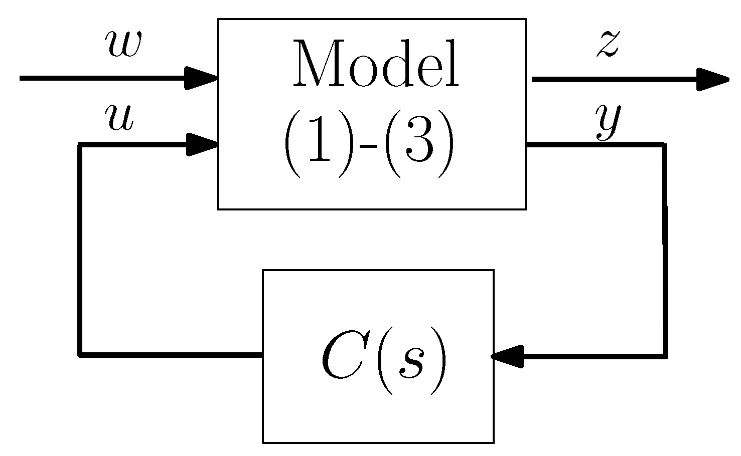
As concerns the problem to provide closed-loop robustness in the presence of modeling uncertainty, different control approaches can be used. A first method is to solve an control problem to design a robust controller [12,13,39]. However, this technique is unsuited to SG with high penetration of RESs. With reference to model (1)–(3), assuming that can be stabilized and is detectable, the robust control design synthesizes the controller by minimizing the infinite-norm of an appropriate matrix of the nominal closed-loop system, which relates the disturbance input to the controlled output , see Figure 4.
The solution of the optimization problem is numerical, because there is no analytic method. In addition, the solution is not unique, so it is usually sufficient to obtain a controller which satisfies the following condition
with . Using matrix representation, is an controller, if and only if there exists a symmetric matrix such that [40]
where
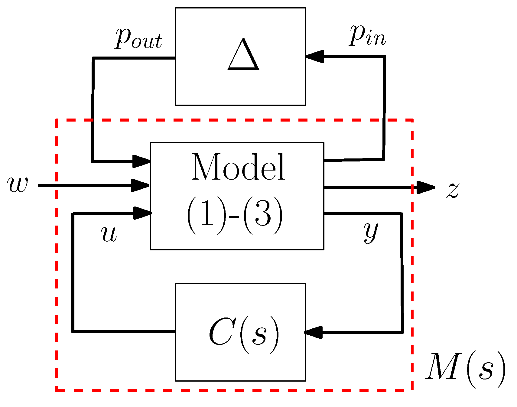
In the robust control, the considered uncertainty is of the unstructured type. However, this type of uncertainty gives conservative results in the design procedure. To solve this problem, it is necessary to adopt the structured representation of the uncertainty. For this type of uncertainty, a different technique employed in the synthesis of a robust controller for MGs is based on the use of structured singular value [41,42,43,44,45]. The standard scheme of M- configuration is shown in Figure 5 where and are the exogenous perturbation signals representing the input and output of the uncertain diagonal block . For a given M- configuration, robust stability is guaranteed if and only if [30]
where
being the largest singular value. Also in this case, there are no standard analytical methods to calculate the optimal controller in the -sense.
In the case of perturbation with additive model, see (8), and considering the following factorization for the uncertain matrix
it is possible to state that the perturbed closed-loop system remains stable if [30]
where
This approach has been adopted in [6] in the case of a DN with only PV systems.
In the case of the input multiplicative model of the unstructured uncertainty, see (9), matrix M in (14) assumes the expression
while in the case of output multiplicative model, see (9), the expression of M is given by
Always in case of perturbation with additive model (8), an alternative formulation to the problem of designing a robust controller can be found in [9]. In particular the following theorem holds: assume that and are stable. If satisfies
then the closed-loop system is stable.
The main problem of and -based robust techniques is that the order of the obtained controller is at least equal to that of the plant and usually higher because of the inclusion of weight matrices. This represents a serious drawback in the case of several RESs modeled according to (1)–(3). These control laws may be too complex with regards to practical implementation. For this purpose, one can reduce the order of the controller by adopting different techniques such as Hankel-norm approximation, truncation, and balanced realizations [37].
The MPC based design has been recently studied as an alternative to and -based robust control techniques in SG control [10,11,46,47,48]. A comparison between MPC and is proposed in [49]. The adoption of the MPC is useful, for example, when sensitivity matrices are employed to express, in an approximated way, voltages and power flows variations with respect to changes in the control variables. However, these sensitivity matrices are affected by inaccuracies because they are obtained without considering the variation of load powers from voltages; in fact, such a relationship is not well known in practice. A robust controller designed according to the MPC technique accounts for these uncertainties. The MPC is a control technique adopted mainly to predict in an optimal sense the system’s behavior on a future time interval. The basic concept of the MPC is the following: at step k, using the latest available measurements, the controller calculates, in an optimal way, the change of control variables, , from k until , with the aim to meet a target at the end of the prediction interval, i.e., at , where and are the control and prediction intervals, respectively. The main objective is to minimize while satisfying a set of appropriate limits. This leads to solve a standard Quadratic Programming problem.
An interesting approach to guarantee robustness in SG is based on the use of the backstepping technique [50]. The backstepping approach has attracted great attention from the control community in many areas of research due to its recursive design for nonlinear system or systems that contain uncertainties. The design philosophy is to decompose a complex system into multiple small-scale subsystems. Subsequently, for each subsystem, using a control Lyapunov function that employs the states of the system as virtual inputs for the subsystems, it is possible to obtain the original control law for global stability and regulation. Recently, the backstepping technique has been applied also in the contest of SG control and stability to cope with non-linearity and uncertainties in the SG model [51,52,53]. However, when the order of the system increases, the number of states grows as well. Then, difficulties to implement the controller may arise.
A robust technique that is particularly appreciated for its robustness properties is the Sliding Mode Control (SMC). In the last years, some papers have proposed the use of the SMC to meet control objectives such as frequency and voltage regulation in MG [54,55,56,57,58]. The main idea of the SMC is to force the system’s states into a particular domain of the state-space, named the sliding surface. The SMC has the scope of maintaining the states in the proximity of the sliding surface once the surface is reached. However, since the control law is discontinuous, chattering effects arise. To alleviate this effect it is necessary to increase the order of the sliding mode enforced by the controller. This may lead to controllers of high-order.
A test is also available to validate the robustness in the presence of uncertainty in the matrix . In particular, in the closed-loop matrix in (13) it is assumed that . The test is based on the use of the real stability radius, as reported in [5]. The real stability radius of a matrix triple , with Hurwitz-stable, is defined by, see [59,60]
The value of can be carried out at low computational cost as the univariate function to be minimized is unimodal. Hence the use of the real stability radius allows to find the largest singular value of the perturbation matrix , which makes the closed-loop system unstable
Finally, advantages and shortcomings of the described techniques are briefly summarized in Table 1.
4. Illustrative Simulation
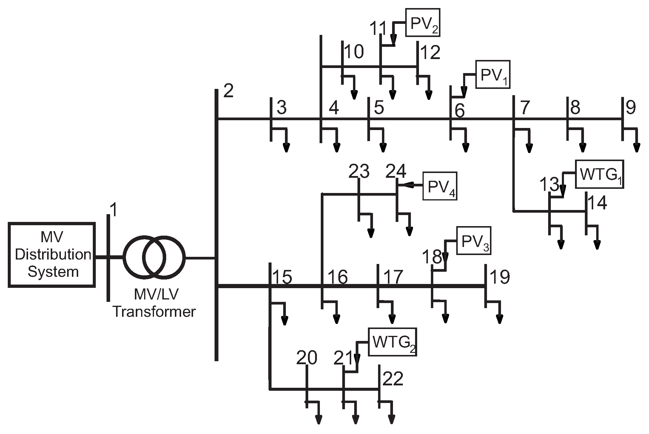
To give evidence of the potential of the described robust control techniques, an illustrative simulation is reported hereafter. A 24 nodes test system with 4 PVs and 2 WTGs is shown in Figure 6. The RES penetration is large: there are 6 nodes equipped with RESs out of 24 total nodes. Moreover, the limited extension of the DN causes a strong interaction among the control loops. Details about the simulated test system are reported in [8]. The two simulations have been developed in the PSCAD-EMTDC environment [61].
The robust technique adopted to design the voltage controller of any RES is described in [8]. This method is based on model (7); operating conditions variations (such as variability of solar irradiance and wind speed) representing model uncertainty are described by model (8); robust stability is guaranteed according to condition (15).
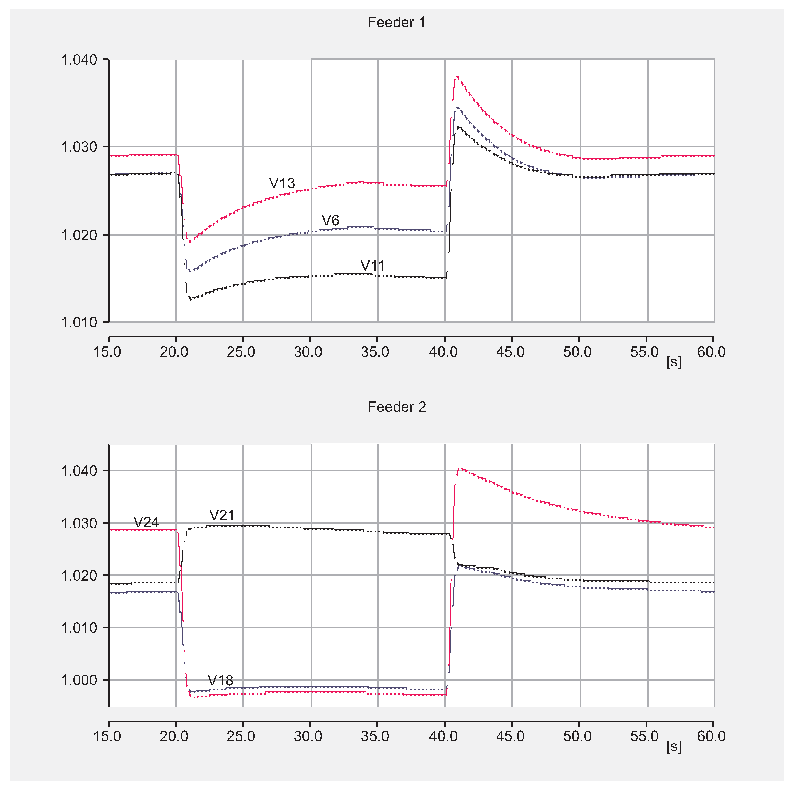
Figure 7 reports the time evolution of the regulated voltage at the PCC of any RES in the presence of a variation of the solar irradiance. In particular, the WTGs are subject to a 10 m/s constant wind speed, and the effect of passing cloud is simulated. The solar irradiance decreases from 1000 W/m to 200 W/m. All the voltages are perturbed due to the significant impact of the active power flows. Figure 7 clearly shows the ability of robust controllers to counteract the effects of this perturbation, thus preserving SG stability. The voltage regulation is satisfactory.
Conversely, Figure 8 reports the time evolution of the same regulated voltage in the presence of variation in the wind speed. In particular, the PVs are subject to a 1000 W/m constant solar irradiance. The WTGs are subject to a variable wind speed; in particular the wind speed decreases from 10 m/s to 5 m/s and afterwards increases up to 8 m/s. Additionally, in this case, the controllers guarantee SG robust stability and voltage regulation.
5. Conclusions
This short study has emphasized how, in front of the application of well-known robust control techniques, the problem to guarantee stability in the presence of model uncertainty, bounded disturbances and mutual interactions among control loops can successfully be solved. The paper has a scholarly nature and is aimed at the control community to give an overview through robust control techniques as well as provide a discussion about challenges and models. The paper has reviewed the most important control approaches described in various articles, as reported in the references. Some important challenges, such as the need of a suitable model of the SG as well as the selection of an appropriate control technique to reject the adverse effects due to both interactions among control loops and model uncertainty are discussed. Finally, an illustrative simulation has been reported to validate the potential of the robust control theory.
Funding
This research was funded by the Italian Ministry of University and Research by the special grant “Dipartimenti di eccellenza”.
Conflicts of Interest
The author declares no conflict of interest.
References
- Eltigani, D.; Masri, S. Challenges of integrating renewable energy sources to smart grids: A review. Renew. Sustain. Energy Rev. 2015, 52, 770–780. [Google Scholar] [CrossRef]
- Ferreira, P.; Carvalho, P.; Ferreira, L.; Ilic, M. Distributed Energy Resources Integration Challenges in Low-Voltage Networks: Voltage Control Limitations and Risk of Cascading. IEEE Trans. Sustain. Energy 2013, 4, 82–88. [Google Scholar] [CrossRef]
- Bevrani, H. On Future of Robust Control in Smart Grids. In Proceedings of the IEEE Conference on Smart Grid (SGC), Tehran, Iran, 9–10 December 2014; pp. 1–2. [Google Scholar]
- Christakou, K.; Paolone, M.; Abur, A. Voltage Control in Active Distribution Networks Under Uncertainty in the System Model: A Robust Optimization Approach. IEEE Trans. Smart Grid 2018, 9, 5631–5642. [Google Scholar] [CrossRef]
- Etemadi, A.; Davison, E.J.; Iravani, R. A Decentralized Robust Control Strategy for Multi-DER Microgrids—Part I: Fundamental Concepts. IEEE Trans. Power Deliv. 2012, 27, 1843–1853. [Google Scholar] [CrossRef]
- Fusco, G.; Russo, M. Robust MIMO Design of Decentralized Voltage Controllers of PV Systems in Distribution Networks. IEEE Trans. Ind. Electron. 2017, 64, 4610–4620. [Google Scholar] [CrossRef]
- Khargonekar, P.; Georgiou, T.; Pascoal, A. On the Robust Stabilizability of Linear Time-Invariant Plants with Unstructured Uncertainty. IEEE Trans. Autom. Control 1987, AC-32, 201–207. [Google Scholar] [CrossRef]
- Fusco, G.; Russo, M. Tuning of multivariable PI robust controllers for the decentralized voltage regulation in grid-connected distribution networks with Distributed Generation. Springer Int. J. Dyn. Control 2020, 8, 278–290. [Google Scholar] [CrossRef]
- Cruz, J.; Freudenberg, J.; Looze, D. A Relationship Between Sensitivity and Stability of Multivariable Feedback Systems. IEEE Trans. Autom. Control 1981, 26, 66–74. [Google Scholar] [CrossRef]
- Farina, M.; Guagliardi, A.; Mariani, F.; Sandroni, C.; Scattolini, R. Model predictive control of voltage profiles in MV networks with distributed generation. Control Eng. Pract. 2015, 34, 18–29. [Google Scholar] [CrossRef] [Green Version]
- Nassourou, M.; Blesa, J.; Puig, V. Robust Economic Model Predictive Control Based on a Zonotope and Local Feedback Controller for Energy Dispatch in Smart-Grids Considering Demand Uncertainty. Energies 2020, 3, 696. [Google Scholar]
- Hossain, M.J.; Pota, H.R.; Mahmud, A.; Aldeen, M. Robust Control for Power Sharing in Microgrids With Low-Inertia Wind and PV Generators. IEEE Trans. Sustain. Energy 2015, 6, 1067–1077. [Google Scholar] [CrossRef]
- Huang, L.; Xin, H.; Dorfler, F. H-infinity Control of Grid-Connected Converters: Design, Objectives and Decentralized Stability Certificates. IEEE Trans. Smart Grids 2020, 11, 3805–3816. [Google Scholar] [CrossRef]
- Rafiee, A.; Batmani, Y.; Bevrani, H.; Kato, T. Robust MIMO Controller Design for VSC-based Microgrids: Sequential Loop Closing Concept and Quantitative Feedback Theory. IEEE Trans. Smart Grid Early Access 2021. [Google Scholar] [CrossRef]
- Mahmud, M.; Hossain, M.; Pota, H.; Oo, A. Robust Nonlinear Distributed Controller Design for Active and Reactive Power Sharing in Islanded Microgrids. IEEE Trans. Energy Convers. 2014, 29, 893–903. [Google Scholar] [CrossRef]
- Blaabjerg, F.; Chen, Z.; Kjaer, S. Power electronics as efficient interface in dispersed power generation systems. IEEE Trans. Power Electron. 2004, 19, 1184–1194. [Google Scholar] [CrossRef]
- Figueres, E.; Garcera, G.; Sandia, J.; Gonzalez-Espin, F.; Rubio, J. Sensitivity study of the dynamics of three-phase photovoltaic inverters with an LCL grid filter. IEEE Trans. Ind. Electron. 2009, 56, 706–717. [Google Scholar] [CrossRef] [Green Version]
- Rahimi, M.; Parniani, M. Transient Performance Improvement of Wind Turbines With Doubly Fed Induction Generators Using Nonlinear Control Strategy. IEEE Trans. Energy Convers. 2010, 25, 514–525. [Google Scholar] [CrossRef]
- Campestrini, V.; Conio, G.; Galdi, V.; Massa, G.; Piccolo, A. Optimal Decentralized Voltage Control for Distribution Systems With Inverter-Based Distributed Generators. IEEE Trans. Power Syst. 2014, 29, 230–241. [Google Scholar]
- Zhang, Z.; Ochoa, L.; Valverde, G. A Novel Voltage Sensitivity Approach for the Decentralized Control of DG Plants. IEEE Trans. Power Syst. 2018, 3, 1566–1576. [Google Scholar] [CrossRef] [Green Version]
- Sansawatt, T.; Ochoa, L. Smart decentralized control of DG for voltage and thermal constraint management. IEEE Trans. Power Syst. 2012, 27, 1637–1645. [Google Scholar] [CrossRef]
- Fazio, A.D.; Russo, M.; Valeri, S.; Santis, M.D. Linear method for steady-state analysis of radial distribution systems. Int. J. Electr. Power Energy Syst. 2018, 99, 744–755. [Google Scholar] [CrossRef]
- Delghavi, M.; Yazdani, A. A Unified Control Strategy for Electronically Interfaced Distributed Energy Resources. IEEE Trans. Power Deliv. 2012, 27, 803–812. [Google Scholar] [CrossRef]
- Fusco, G.; Russo, M. A Decentralized Approach for Voltage Control by Multiple Distributed Energy Resources. IEEE Trans. Smart Grid 2021, 12, 3115–3127. [Google Scholar] [CrossRef]
- Fusco, G.; Russo, M.; Santis, M.D. Decentralized Voltage Control in Active Distribution Systems: Features and Open Isuue. Energies 2021, 14, 2563. [Google Scholar] [CrossRef]
- Braslavsky, J.H.; Collins, L.; Ward, J.K. Voltage Stability in a Grid-Connected Inverter With Automatic Volt-Watt and Volt-VAR Functions. IEEE Trans. Smart Grid 2019, 10, 84–94. [Google Scholar] [CrossRef]
- Nazari, M.H.; Ilic, M.; Lopes, J. Small-signal stability and decentralized control design for electric energy systems with a large penetration of distributed generators. Control Eng. Pract. 2012, 20, 823–831. [Google Scholar] [CrossRef] [Green Version]
- Ranamuka, D.; Agalgaonkar, A.; Muttaqu, K. Online Voltage Control in Distribution Systems With Multiple Voltage Regulating Devices. IEEE Trans. Sustain. Energy 2014, 5, 617–628. [Google Scholar] [CrossRef]
- Osório, C.; Koch, G.; Borin, L.; Nascimento, M. Robust control of grid-connected converters under wide grid impedance variation. In Proceedings of the 29th Mediterranean Conference on Control and Automation (MED), Gramado City, Brazil, 15–18 September 2019; pp. 1–6. [Google Scholar]
- Skogestad, S.; Postlethwaite, I. Multivariable Feedback Control Analysis and Design; John Wiley & Sons: Hoboken, NJ, USA, 2005. [Google Scholar]
- Jafarian, H.; Cox, R.; Enslin, J.; Bhowmik, S.; Parkhideh, B. Decentralized Active and Reactive Power Control for an AC-Stacked PV Inverter With Single Member Phase Compensation. IEEE Trans. Ind. Appl. 2011, 2, 363–373. [Google Scholar] [CrossRef]
- Juanjuan, W.; Chuang, F.; Yao, Z. Design of WAMS-Based Multiple HVDC Damping Control System. IEEE Trans. Smart Grid 2018, 54, 345–355. [Google Scholar] [CrossRef]
- Garcia, D.; Karimi, A.; Longchamp, R. PID controller design for multivariable systems using Gershgoring bands. In Proceedings of the IFAC World Congress, Prague, Czech Republic, 3–8 July 2005. [Google Scholar]
- Labibi, B.; Lohmann, B.; Sedigh, A.; Maralani, P. Decentralized Robust control of Large-Scale systems via Sensitivity Reduction to the Interactions. In Proceedings of the IEEE American Control Conference, Chicago, IL, USA, 28–30 June 2000; pp. 819–823. [Google Scholar]
- Grosdidier, P.; Morari, M. Interaction Measures for systems Under Decentralized Control. Automatica 1986, 22, 309–319. [Google Scholar] [CrossRef]
- Fusco, G.; Russo, M. A Procedure to Determine the Droop Constants of Voltage Controllers Coping with Multiple DG Interactions in Active Distribution Systems. Energies 2020, 13, 1935. [Google Scholar] [CrossRef] [Green Version]
- Skogestad, S.; Morari, M. Letters to Editor. Am. Inst. Chem. Eng. AIChE 1987, 33, 701–702. [Google Scholar]
- European Parliament; Council of the EU. Directive (EU) 2019/944 on Common Rules for the Internal Market for Electricity and Amending DIRECTIVE 2012/27/EU. Available online: https://eur-lex.europa.eu/legal-content/EN/TXT/PDF/?uri=CELEX:32019L0944 (accessed on 5 June 2019).
- Tafti, A. Using H∞ controller for monitoring and control of smart grids. In Proceedings of the IEEE International Conference on Smart Energy Grid Engineering (SEGE), UOIT, Oshawa, ON, Canada, 14–17 August 2017; pp. 1–6. [Google Scholar]
- Zhou, K.; Doyle, J. Essentials of Robust Control; Prentice Hall: Hoboken, NJ, USA, 1997. [Google Scholar]
- Al-Muhanna, A.; Al-Nujaimi, A.; Al-Baiyat, S. Robust H∞ and μ-Synthesis frequency control for two-bus islanded microgrid. In Proceedings of the Saudi Arabia Smart Grid (SASG), Jeddah, Saudi Arabia, 12–14 December 2017. [Google Scholar]
- Bevrani, H.; Feizi, M.; Ataee, S. Robust Frequency Control in an Islanded Microgrid: H∞ and μ Synthesis Approaches. IEEE Trans. Smart Grids 2016, 7, 706–717. [Google Scholar] [CrossRef] [Green Version]
- Kahrobaeian, A.; Mohamed, Y.A. Direct single-loop μ-synthesis voltage control for suppression of multiple resonances in microgrids with power-factor correction capacitors. IEEE Trans. Smart Grid 2013, 4, 1151–1161. [Google Scholar] [CrossRef]
- Li, P.; Yin, Z.; Li, Y. The realization of flexible photovoltaic power grid-connection μ-synthesis robust control in microgrid. In Proceedings of the IEEE Power and Energy Systems General Meeting Conference Exposition, National Harbor, MD, USA, 27–31 July 2014; pp. 1–5. [Google Scholar]
- Zhu, L.; Chen, J.; Niu, S.; Liu, J.; Guo, J.; Huo, C. μ-Synthesis Robust Control of Variable Speed Wind Turbine Generators for Participating in Microgrid Frequency Regulation. In Proceedings of the IEEE Sustainable Power and Energy Conference (iSPEC), Chengdu, China, 23–25 November 2020; pp. 1–6. [Google Scholar]
- Shan, Y.; Hu, J.; Guerrero, J.M. A Model Predictive Power Control Method for PV and Energy Storage Systems With Voltage Support Capability. IEEE Trans. Smart Grid 2020, 11, 1018–1029. [Google Scholar] [CrossRef]
- Valverde, G.; Cutsem, T.V. Model Predictive Control of Voltages in Active Distribution Networks. IEEE Trans. Smart Grid 2013, 4, 2152–2161. [Google Scholar] [CrossRef] [Green Version]
- Zhao, H.; Wu, Q.; Wang, J.; Liu, Z.; Shahidehpour, M.; Xue, Y. Combined Active and Reactive Power Control of Wind Farms Based on Model Predictive Control. IEEE Trans. Energy Convers. 2017, 33, 1177–1187. [Google Scholar] [CrossRef] [Green Version]
- Sedhom, B.; El-Saadawi, M.; Hatata, A.; Abd-Rabo, E.H. H-Infinity versus model predictive control methods for seamless transition between islanded-and grid-connected modes of microgrids. IET Renew. Power Gener. 2019, 14, 856–870. [Google Scholar] [CrossRef]
- Zhang, Y.; Li, S.; Zhu, Q. Backstepping-enhanced decentralised PID control for MIMO process with an experimental study. IET Control Theory Appl. 2007, 1, 704–712. [Google Scholar] [CrossRef] [Green Version]
- de Araujo, M.; Rocha, L.; Martins, L.; Vieira, R. Multiloop Current Control Strategy for a Grid-connected VSI with LCL Filter Using Backstepping and Proportional+Resonant Controller. In Proceedings of the IEEE PES Innovative Smart Grid Technical Conference—Latin America (ISGT Latin America), Gramado, Brazil, 15–18 September 2019; pp. 1–6. [Google Scholar]
- Martin, A.; Cano, J.; Silva, J.; Vázquez, J. Backstepping Control of Smart Grid-Connected Distributed Photovoltaic Power Supplies for Telecom Equipment. IEEE Trans. Energy Convers. 2015, 30, 1496–1504. [Google Scholar] [CrossRef]
- Roy, T.; Mahmud, M.; Islam, S.; Rajasekar, N.; Muttaqi, K.; Oo, A. Nonlinear Backstepping Controller Design for Grid-Connected Photovoltaic Systems with Output LC Filters to Improve Dynamic Stability and Power Quality. In Proceedings of the IEEE International Conference on Power Electronics, Smart Grid and Renewable Energy (PESGRE2020), Kochi, India, 2–4 January 2020. [Google Scholar]
- Abbadi, S.; Hamidia, F.; Morsli, A. New MPPT Sliding Mode Approach for Grid Connected PV System. In Proceedings of the IEEE International Conference on Applied Smart Systems, Médéa, Algeria, 24–25 November 2018. [Google Scholar]
- Arbatsofla, S.; Toloei, A.; Soudagary, F.; Naseri, A. DFIG wind turbine control despite the uncertainties in the model using high-order adaptive sliding. In Proceedings of the IEEE Smart Grid Conference, Arlington, VA, USA, 23–26 April 2017. [Google Scholar]
- Cucuzzella, M.; Incremona, G.; Ferrara, A. Third Order Sliding Mode Voltage Control in Microgrids. In Proceedings of the IEEE European Control Conference, Linz, Austria, 15–17 July 2015; pp. 1–6. [Google Scholar]
- Ruiz-Zea, C.; Jiménez-Rodríguez, E.; Cañedo-Castañeda, J.; Loukianov, A. Sliding Mode Control for a Distributed Generation Unit Based on Photovoltaic Sources. In Proceedings of the IEEE North American Power Symposium, Fargo, ND, USA, 9–11 September 2018. [Google Scholar]
- Shanoob, M.; Iqbal, K. State Feedback Sliding Mode Control Law Design for Grid-Connected Wind Turbine Model. In Proceedings of the 7th International Conference on Smart Energy Grid Engineering, Oshawa, ON, Canada, 12–14 August 2019. [Google Scholar]
- Chang, Y.H.; Wise, G. Theory and Application of robust Stability analysis on State Space Using Stability Radii. In Proceedings of the IEEE American Control Conference, Baltimore, MD, USA, 29 June–1 July 1994; pp. 1–6. [Google Scholar]
- Qiu, L.; Bernhardsson, B.; Rantzer, A.; Davison, E.; Young, P.; Doyle, J. A Formula for Computation of the Real Stability Radius. Automatica 1995, 31, 879–890. [Google Scholar] [CrossRef] [Green Version]
- Manitoba-HVDC Research Center. PSCAD User’s Guide; Manitoba HVDC Research Centre Inc.: Winnipeg, MB, Canada, 2005. [Google Scholar]
Figure 1.
Smart Grid.

Figure 2.
Schematic diagram of a PV system connected to the grid.

Figure 3.
Schematic diagram of the wind turbine generator (WTG) connected to the grid.

Figure 4.
standard representation.

Figure 5.
M- standard representation for design.

Figure 6.
Test system.

Figure 7.
Time evolution of the voltages in presence of variation of the solar irradiance.

Figure 8.
Time evolution of the voltages in the presence of variation in the wind speed.


Table 1.
Evaluation of the described techniques.
| Technique | Advantages/Features | Shortcomings |
|---|---|---|
| control | Sub-optimal solution Robust against disturbances Suited to unstructured uncertainty Availability of numerical tools | Solution numerically complicated Not unique solution for MIMO plants High-order of the controller Requires weights matrices Usually applied to MG |
| MPC | Prediction model can be MIMO Robust against disturbances Availability of numerical tools Handles input-output constraints | Needs real-time computations Requires data handling capability, horizons Usually applied to MG Not suited to decentralized approaches |
| Structured singular value () | Suited to structured uncertainty Availability of numerical tools Less conservative | High-order of the controller No closed-form methods for computation Usually applied to MG |
| Condition (14) | Different design techniques Allows the use of decentralized control techniques Suited also to large SG | Conservative Requires factorization In the case of complex perturbation <1 may not be possible in practice Only for additive model of the unstructured uncertainty |
| Condition (15) | Different design methods Allows the use of decentralized control techniques Suited also to large SG | Conservative In the case of complex perturbation <1 may not be possible in practice Only for additive model of the unstructured uncertainty |
| Backstepping | Recursive design Decentralized approach | Number of states Not suited to SG of large dimension |
| Sliding mode control | Low computational burden Robust against disturbances Finite-time converge | Chattering problems No numerical tools Limit cycles if the gain is not accurately designed Not suited to SG of large dimension |
Publisher’s Note: MDPI stays neutral with regard to jurisdictional claims in published maps and institutional affiliations. |
© 2021 by the author. Licensee MDPI, Basel, Switzerland. This article is an open access article distributed under the terms and conditions of the Creative Commons Attribution (CC BY) license (https://creativecommons.org/licenses/by/4.0/).
Share and Cite
MDPI and ACS Style
Fusco, G. On the Use of Robust Techniques in Smart Grid Control. Energies 2022, 15, 7. https://doi.org/10.3390/en15010007
AMA Style
Fusco G. On the Use of Robust Techniques in Smart Grid Control. Energies. 2022; 15(1):7. https://doi.org/10.3390/en15010007
Chicago/Turabian StyleFusco, Giuseppe. 2022. "On the Use of Robust Techniques in Smart Grid Control" Energies 15, no. 1: 7. https://doi.org/10.3390/en15010007
Note that from the first issue of 2016, this journal uses article numbers instead of page numbers. See further details here.