
Dynamic Analysis of Wind Turbine Gearbox Components

School of Electrical, Mechanical and Mechatronic Systems, University of Technology Sydney, Sydney 2000, Australia
*
Author to whom correspondence should be addressed.
Energies 2016, 9(2), 110; https://doi.org/10.3390/en9020110
Submission received: 26 October 2015
/
Revised: 10 December 2015
/
Accepted: 28 January 2016
/
Published: 17 February 2016
Abstract
:This paper studies the dynamic response of a wind turbine gearbox under different excitation conditions. The proposed 4 degree-of-freedom (DOF) dynamic model takes into account the key factors such as the time-varying mesh stiffness, bearing stiffness, damping, static transmission error and gear backlash. Both the external excitation due to wind and the internal excitation due to the static transmission error are included to represent the gearbox excitation conditions. With the help of the time history and frequency spectrum, the dynamic responses of wind turbine gearbox components are investigated by using the numerical integration method. This paper explains under which conditions the fretting corrosion, as one of the wind turbine gearbox failure modes, may occur. Furthermore, it is observed that the external excitation fluctuation has large influence on the dynamic responses of both the gears and bearings.
1. Introduction
The wind turbine drivetrain converts high torque on the main shaft to low torque on the high-speed shaft to meet the electromechanical requirements of the generator. Gearbox failure has been the major cause of many reliability problems for the modern wind energy industry since its inception [1]. Although vibrations in wind turbine gearboxes have received significant attention from both the industry and researchers, to the authors’ best knowledge the fundamental failure mechanisms have not yet been fully understood due to the complexity of its nature,. In the context of vibrations, a wind turbine gearbox can be considered as a complex dynamic system subjected to highly complex loading conditions. The torque applied on the gearbox is driven by the rotor blades under fluctuating wind, and the variable loads inherently exist within the entire gearbox. Under such conditions, the fatigue life of wind turbine gearboxes is significantly affected [2].
The objective of the present work is to study the dynamic responses of wind turbine gearbox components under different excitation conditions. The proposed model considers both the low-frequency excitation due to the external driving torque and the high-frequency internal excitation due to the static transmission error. Other factors include the time-varying mesh stiffness, bearing stiffness, damping and gear backlash. The proposed dynamic model can be used to study the fundamental mechanism of wind turbine gearbox components including gears and bearings, which could provide useful information to reduce the possibility of the gearbox failures at an early stage.
2. A Brief Review on Wind Turbine Gearbox Dynamics
A brief review of the existing studies regarding wind turbine gearboxes are presented in this section. Peeters, Vandepitte, Sas and Helsen [3,4,5,6] developed three types of multi-body models to study the dynamic responses of wind turbine gearbox components. Feng and Zuo [7] developed a torsional model of the gearbox used for diagnosing multiple gear faults. Abboudi et al. [8] studied the dynamic behavior of a two-stage spur gear system used in wind turbines. Dong, Xing and Moan [9] investigated the gear dynamics in time domain with the torque only, and found that the reverse problem is severe at low speed and suggested a generator control. Later Xing and Moan [10] developed a multi-body model of the planet carrier of wind turbine gearboxes and investigated the influence of the gearbox components using the finite element model. Oyague [11] discussed a number of analytical models for the analysis of wind turbine gearbox components, and correlated the parameters obtained from these models with the gearbox design process. He [12] also provided the general information, configuration and specifications of the wind turbine gearbox components using the Gearbox Reliability Collaborative (GRC) layout (the GRC project was initiated by the National Renewable Energy Laboratory (NREL) in 2007; the project includes modelling, analysis, field testing, condition monitoring and the development of failure database, etc.). Zhu, Chen and Liu [13] noted that the vibrations appear to be at peak on the low-speed shaft and the internal components of the high-speed parallel gear stage. Whittle and Trevelyan [14] studied the impact of the misalignment on the high-speed gear stage and generator bearings. They found that the fatigue life of the gearbox bearings in high-speed gear stage were not significantly affected by the misalignment but that of the generator bearings can be significantly reduced. Zhang, Nielsen, Blaabjerg and Zhou [15] presented a 13-DOFs model of an offshore wind turbine by using the Euler-Lagrangian approach. Zhao and Ji [16] studied the torsional vibrations of wind turbine gearbox having two planetary gear stages and one parallel gear stage. It was found that the external excitation has the most influence on the torsional vibrations of the wind turbine gearbox components. The mesh stiffness, being another significant factor, has more influence than the static transmission error.
Furthermore, wind turbine gearboxes may consist of both the planetary and parallel gear stages depending on the capacity requirement of a wind turbine. In the study of gear dynamics, Ozguven and Houser [17] established a nonlinear model of a spur gear and observed that the transmission error has less effect on the dynamic responses of gears than the mesh stiffness. Kahraman and Singh [18] studied the frequency response of a nonlinear geared rotor-bearing system. Kahraman also developed a linear dynamic model of a helical gear pair including the shaft and bearing flexibilities and studied a three-dimensional dynamic model of a multi-mesh helical gear train [19,20]. It was observed that only the coupled transverse-axial-torsional modes are sensitive to the helical angle and loading conditions, and the dynamic response could be influenced drastically by the positions of gears. Spitas and Spitas [21] developed a nonlinear model of a single-stage spur gear reducer by considering the effects of pitch errors, tooth separation, coupling and profile corrections. The results showed that the optimal corrections could reduce the overloads, and a new design recommendation for the profile correction was made based on the results. Later, they [22] derived a modified form for the fundamental gear meshing equations, which improved the solving speed and the stability. They also developed a new form for the equations of the non-conjugate meshing with the solution being fast implemented and stable [23]. Recently, Spitas, Spitas and Amani [24,25] studied the effect of the dedendum coefficient and the tip radius coefficient of spur gears, and generated a new generalized model for calculating the corner penetration at tooth root.
3. Modelling of Wind Turbine Gearbox
3.1. Structure and Components
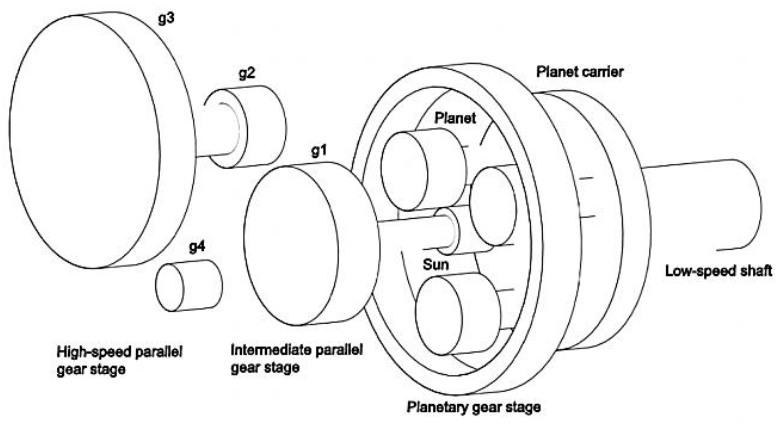
In the proposed gearbox model shown in Figure 1, three gear stages are presented: the low-speed planetary gear stage, the intermediate and high-speed parallel gear stages. Theoretically, the aerodynamic loadings are mostly absorbed by the main shaft bearings, and thus have no influence on the gear teeth except for the driving torque. Therefore, the input load of the proposed dynamic model is limited to torsional load only, and assumed to be applied directly to the planet carrier arm, which transmits the load to planet gears and the sun pinion. The non-torsional loads are assumed to be uncoupled with the gearbox.
The planetary gear stage includes three moving components: planet carrier arm, planet gears and sun pinion. The gearbox housing, planet carrier arm and bedplate are assumed to be rigid, and no relative movements or transmission of forces between shafts are allowed. The planets are supported on the planet carrier arm by shafts with bearings, thus the planets can rotate freely with respect to the planet carrier arm, and split the input load to reduce the load transmitted at each gear mesh. At parallel gear stages, the gears and pinions are also mounted between bearings.
3.2. Derivation of Equations
The present model can be used to predict the dynamic response of wind turbine gearbox components. Both the low-frequency excitation due to wind fluctuations and the high-frequency excitation due to static transmission errors are considered. The external excitation fluctuation is caused by wind, whereas the static transmission error is the overall kinetic error of gear pairs during gear meshes, expressed in the form of periodically time-varying displacement functions [26]. This model also takes into account the key factors such as the time-varying mesh stiffness, bearing stiffness, damping and gear backlash. The time-varying mesh stiffness, as an important source of the internal excitation, fluctuates as the number of gears’ contacting teeth changes during gear meshes. Damping and backlash have been neglected in some of the existing studies on the wind turbine gearboxes [27]. However, large influence of the damping and backlash in the nonlinear behavior was observed during wind turbine emergency stop [28,29]. Thus, damping and gear backlash are included in this model.
A lumped-parameter model of a ring-planet-sun gear pair is illustrated in Figure 2 as an example, the gear deformation during tooth meshes is represented by the time-varying gear mesh stiffness, damping and the static transmission error (specifications of the proposed dynamic model are presented in Section 4). All gears are helical gears, with the helical angle and pressure angle of each gear tooth remaining constant, and are allowed to rotate freely during turbine operation (details of the gear teeth specifications are given in Section 4.3.).
Based on the geometry of gears, the base radius of gears is determined by Equation (1):
where denotes the base radius of gears, denotes the radius of gears and is the pressure angles. The equivalent transverse displacements of the gearbox components along the line of action, caused by their rotational displacements, are determined by Equation (2):
The relative displacement of sun-planet gear mesh on the line of action, caused by rotation, can be expressed as:
The relative displacement of sun-planet gear mesh on the line of action, caused by the translational motions, can be given by:
Combining Equation (3a) and (3b), and taking into account the effect of the static transmission error , yields the total relative displacement of sun-planet gear mesh on the line of action:
Similarly, the relative displacement of ring-planet gear mesh on the line of action, caused by rotation, can be written as
The relative displacement of ring-planet gear mesh on the line of action, caused by the translational motions, can be expressed as
By taking into account the static transmission error of the ring-planet gear mesh, the total relative displacement is:
The relative displacement between the sun pinion and the gear of the intermediate parallel gear stage can be calculated by:
The relative displacement of the gear pair at the intermediate parallel gear stage, caused by rotation, can be expressed by:
The relative displacement of gear pair, caused by the translational motions, is given by:
By considering the static transmission error between the gear and pinion, the total relative displacement is:
The relative displacement between the gears and can be obtained by:
For the high-speed parallel gear stage, the relative displacement of the gear mesh on the line of action, caused by rotation, can be written as:
The relative displacement of gear pairs on the line of action, caused by the translational motions, can be expressed by:
By including the static transmission error between the gear and pinion, the total relative displacement is:
The meshing forces of the gear pairs of the wind turbine gearbox can be determined from the relative displacements of gear meshes represents , , and , . By considering the gear backlash, the meshing forces of gear pairs (e.g., between the ring-planet gear mesh) can be recalculated by Equation (9), where represent the gear meshing stiffness of the ring-planet gear pairs, and given by Equation (10) is the vector form of the nonlinear gear mesh displacement function (no gear backlash exists on shafts). Damping forces can be calculated in a similar way:
The equations of motion of the gearbox components can be obtained by applying the Newton’s laws. For the planet carrier, the equations of motion are given by:
For the sun pinion, the equations of motion are:
For the planet gears, the equations of motion are given by:
For the gear at the intermediate parallel gear stage , the equations of motion are written as:
For the pinion at the intermediate parallel gear stage , the equations of motion are expressed as:
For the gear at the high-speed parallel gear stage , the equations of motion are obtained as:
For the pinion at the high-speed parallel gear stage , the equations of motion are given by:
Substituting the relative displacements of gear meshes given by Equations (3) to (8) into Equations (11) to (17), yields the transverse and translational displacements of gears.
4. Parameter Specifications
4.1. General Information
In simulation, the radius of the rotor blades is 36, the average wind speed is 16 , the air density is 1.21 , and the rotational speed of the rotor blades is 17 . When the rotational speed of the blades is set to be constant, the simulated wind fluctuation results in the fluctuation of the driving torque to the gearbox. Thus, the effects of wind excitation on the gearbox components can be investigated.
4.2. Excitation Conditions
The driving torque , that is applied to the planet carrier as the input to the system, can be calculated by Equation (18), where is the rotational speed of blades, and is the output power generated by the blades, which is given by Equation (19) [30]:
where is the air density, is the radius of the blades, is the average wind speed and is the wind power utilization. By neglecting the power loss in gearbox, the average output torque of the gearbox can be obtained by using Equation (20), where is the gear ratio of the gearbox:
If only the external excitation is considered, the driving torque can be expressed by Equation (21) as a periodic sinusoidal function, where is the constant external driving torque, is the fluctuating external driving torque, represents the external excitation frequency ( and (as in the low frequency range) is chosen to be the external excitation frequency). This usually happens when the wind turbine is parked. Under such a condition, the gears in the gearbox are not allowed to rotate:
It can be predicted that the external excitation results in low frequency responses, whereas the internal excitation results in high frequency responses. The static transmission error function used in Equations (3) to (8) is represented by Equation (22). As the static transmission error is very small, only the fluctuation term is considered. The high-frequency excitations at the meshing frequency are expected during gear mesh ( and the meshing frequencies in the proposed dynamic model are 28.05 , 132.8 and 438.7 ):
When only the internal excitation, caused by the static transmission error , is considered, the internal excitation is given by Equation (23), where is the fluctuating meshing force caused by the static transmission error :
In addition, under the constant rotational speed the meshing frequencies of the wind turbine gearbox components, determined by Equation (24), remain constant during operation for the simplicity in simulation:
where is the rotational speed of the gear and is the teeth number. For the planetary gear stage, is the rotational speed of the planet carrier arm and is the teeth number of the ring gear [31].
4.3. Time-Varying Mesh Stiffness
The teeth mesh stiffness variation of each gear pair is assumed to be approximately proportional to the meshing tooth variation, which is periodic over meshing cycles. Each of the gear meshes has the same shape of mesh tooth variation by neglecting static and dynamic transmission error effects, but they are not in phase with each other. Thus, the mesh stiffness is expressed in the periodic forms in terms of the average and fluctuating mesh stiffnesses as shown in Equation (25), which fluctuates with the change of the contact teeth at the meshing frequency of each gear stage [32]:
where is the meshing frequency, is the average gear mesh stiffness, and is the fluctuating term of the gear mesh stiffness calculated by Equations (26) and (27):
where is the contact ratio, is the length of action given by Equation (28), which is the distance along the line of action between meshing points. The meshing points are the points of beginning and leaving the teeth contact during tooth mesh:
where and are the pitch radii of the gear and pinion, and are the addendum of the gear and pinion, is the pressure angle, and is the center distance of the gear pairs () [33].
It is assumed that the gear tooth behaves like a cantilever beam. Thus, the mean stiffness is calculated by Equation (29) based on the ISO-6336 standard [11,34]:
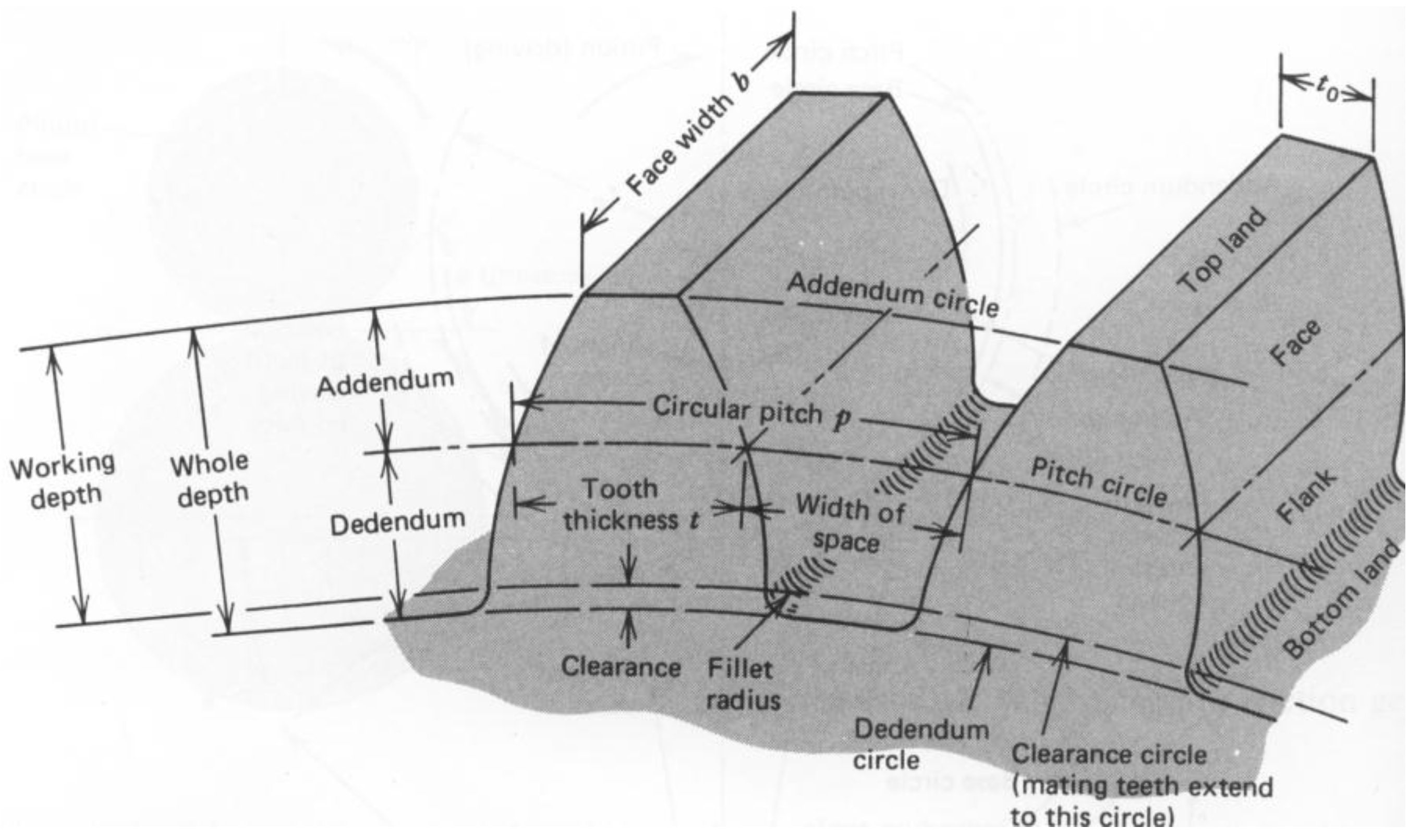
where and are the maximum deflection of the gear tooth calculated by Equation (30), where is the applied load at the tooth tip, is the tooth depth which can be calculated by using the AGMA standard in Table 1 [2], is the area moment of inertia, and is the modulus of elasticity. Figure 3 and Figure 4 present a gear tooth and gear nomenclature:
The mesh stiffness can be calculated using Equations (26) to (30), and the actual values are obtained with the help of Matlab. As the actual values of the mesh stiffnesses vary in simulation due to the gear contact cycles, they cannot be provided in details for brevity. Instead, the gear teeth dimensions used for the proposed model are provided in Table 2. (The “7.5 L” and “14.5 R” in Table 2 represent facing left and facing right.)
4.4. Bearing Stiffness
The bearing stiffness has large influence on the dynamic behaviors of bearings. The elastic displacement of bearings, during the wind turbine operation, would affect the dynamic responses of other gearbox components. The cylindrical roller bearings (CRB) and the full-complement cylindrical roller bearings (fc CRB) are used to support the radial loads, and the tapered roller bearings (TRB) to support axial loads. Table 3 presents the bearing stiffness used in the proposed model.
4.5. Damping
The tooth deformation is represented by the time-varying mesh stiffness and damping in the lumped-parameter model shown in Figure 2. The damping of the teeth mesh is expressed by:
where is the mesh stiffness of the gear pair, is the damping ratio of tooth mesh (varies between 0.03 and 0.17), and are the masses of gear and pinion.
5. Numerical Results and Discussion
This section presents the simulation results of the proposed gearbox model. The ode45 solver in Matlab is used to solve the differential equations. The integration results of the first 1500 periods are discarded prior to recording the steady state solutions. For each meshing cycle, 360 meshing points are sampled in order to capture the sufficient number of data. The analysis focuses on the effects of the excitation conditions on gears and bearings of the wind turbine gearbox with the help of the time histories and FFT spectrums.
5.1. External Excitation only
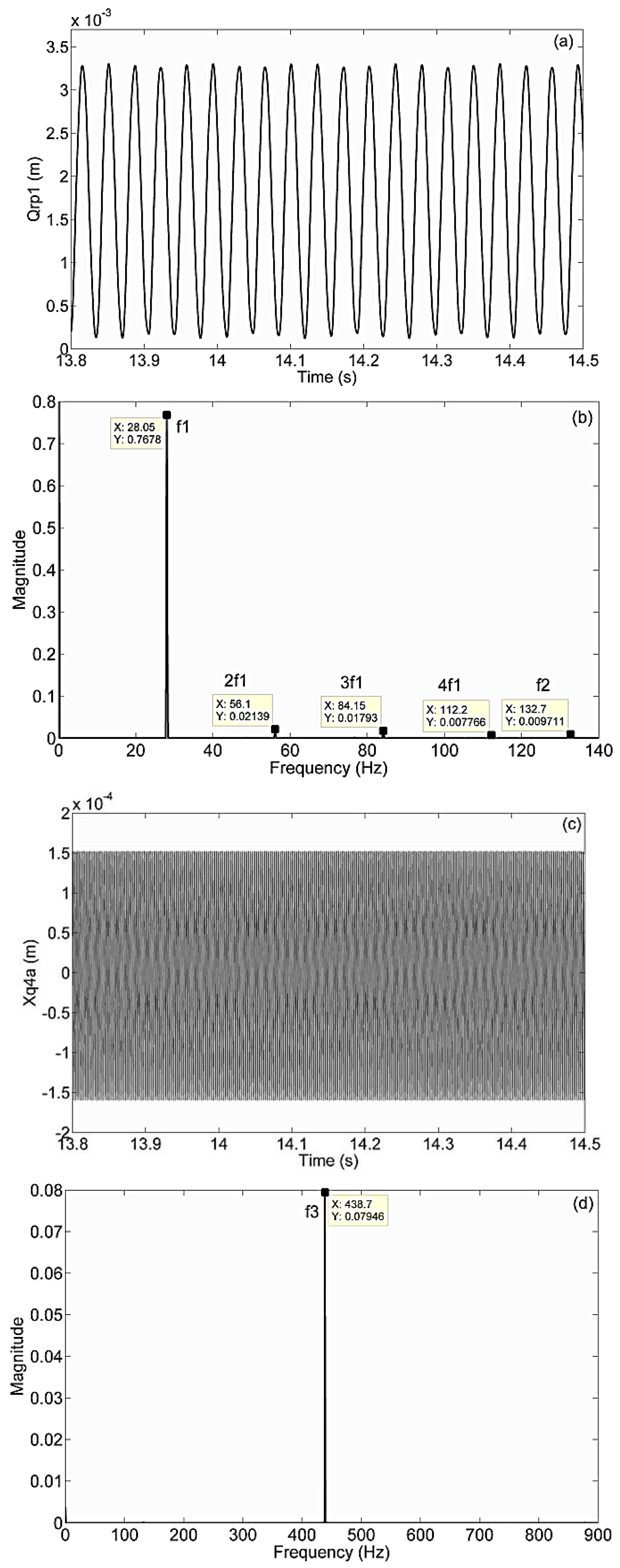
When only the external excitation is considered and the gears are not allowed to rotate, such condition is similar to the situation when the wind turbine is parked. Assuming the driving torque of the gearbox fluctuates with the external excitation frequency , then the total excitation is expressed by Equation (21). Figure 5 shows the dynamic responses of ( represents the relative gear mesh displacement of the ring gear and the first planet gear. As the gearbox gear meshes behave in a similar pattern, only the response of is presented as the example of the gear meshes) and , representing the relative displacements of the ring-planet gear meshes and the axial displacement of the pinion at high-speed parallel gear stage. It is observed that the frequency peak in each FFT spectrum occurs at the external excitation frequency , which indicates that only the external excitation contributes to the vibrations in the gearbox, and the gearbox components only respond to the wind fluctuation. The time histories also show the stability of the dynamic responses of the gearbox components. The magnitude of is much larger than that of . This indicates that the relative displacement of the gear meshes caused by wind fluctuations is much larger than the axial displacement of the gear when the wind turbine is parked. These observations are in good agreements with Errichelo’s findings that the fretting corrosion, as one of the wind turbine gearbox failure modes, normally occurs in gears along a line of action when the turbines are parked [36].
.
5.2. Constant External Excitation
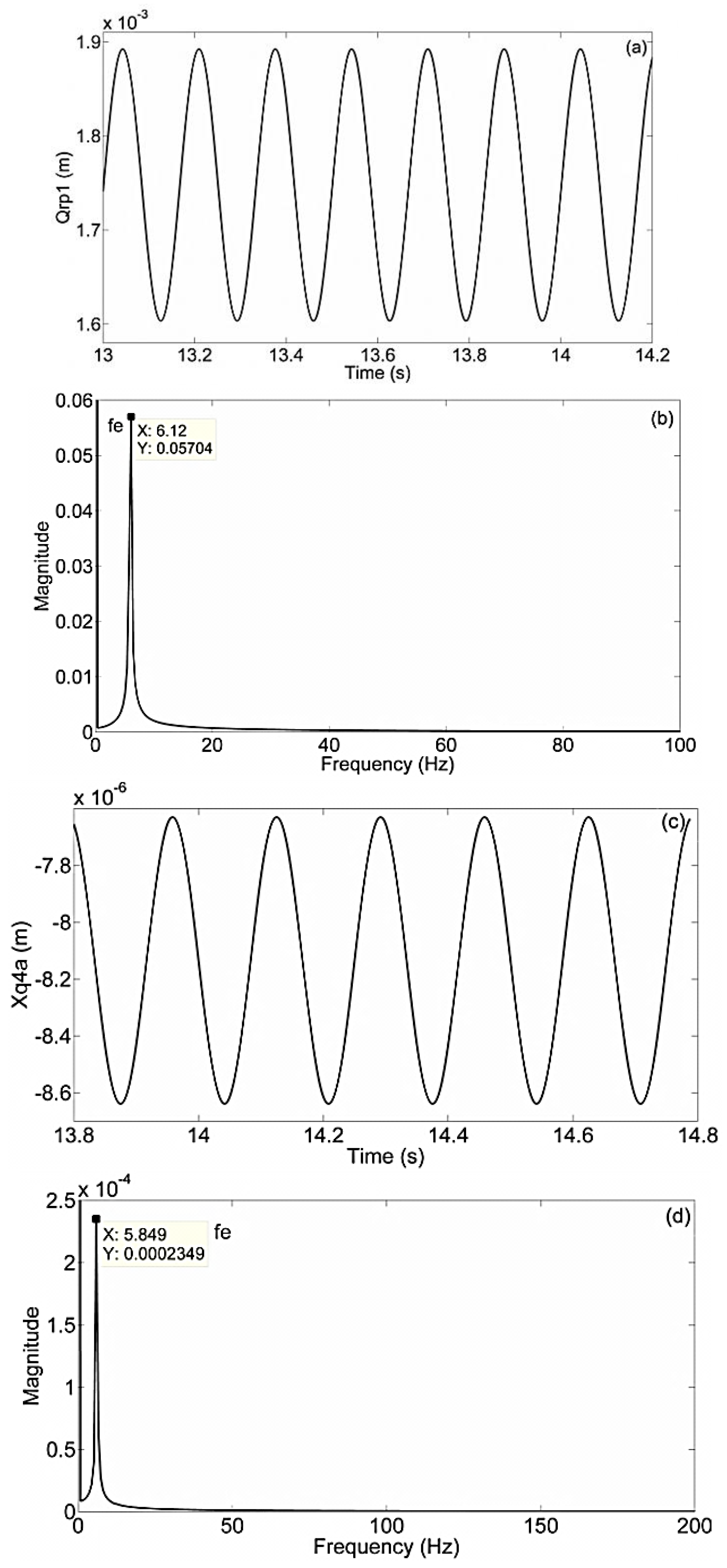
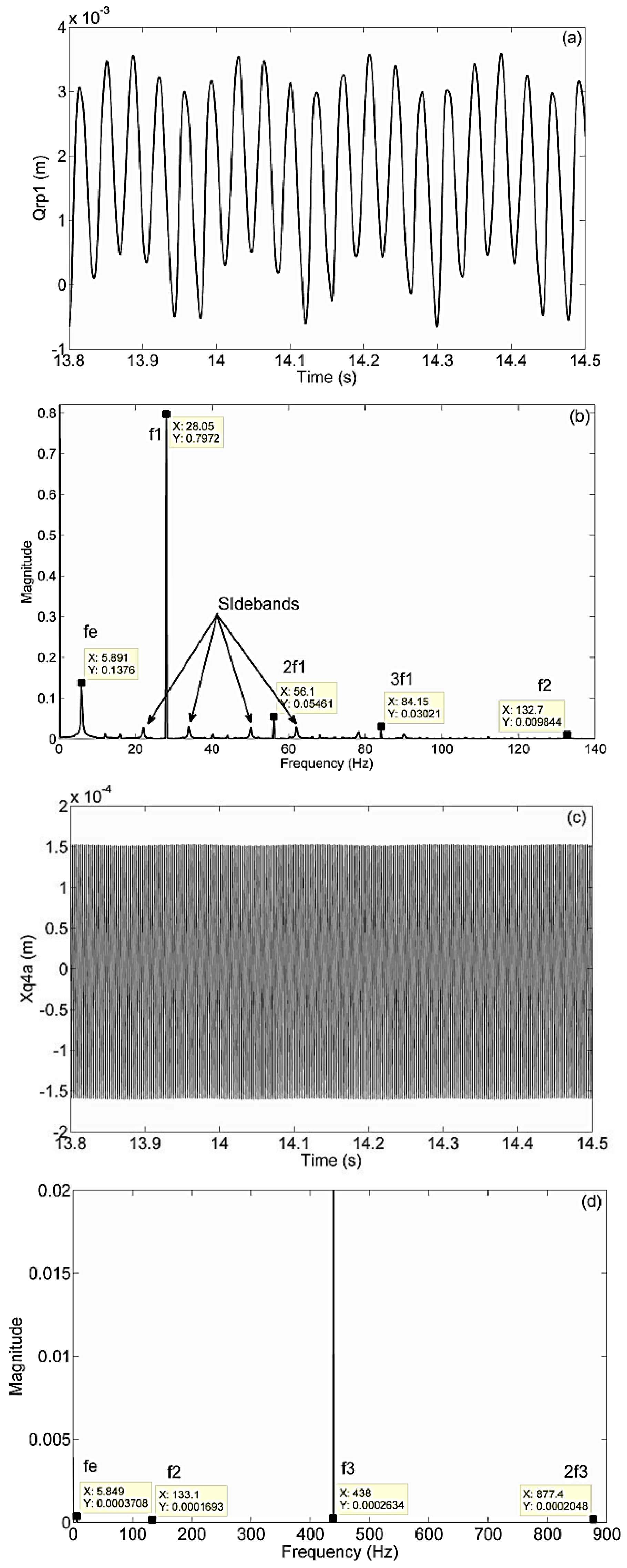
When both the internal and constant external excitations are considered, it is assumed that the turbine operates under ideal condition. The external excitation is constantly applied to the gearbox, and the internal excitation, caused by the static transmission errors , is assumed to fluctuate with the meshing frequencies . Figure 6 shows the dynamic responses of and . The internal excitation provides high-frequency vibrations to the gearbox, thus, the dynamic responses under meshing frequencies are expected to be observed.
.
Figure 6a,b show that is stable and the meshing frequency of the planetary gear stage contributes the most on , while the magnitude of its harmonics and are much smaller than and provides much less effects on . Figure 6c,d exhibit the axial displacement of the bearing at the high-speed parallel gear stage . The frequency peak occurs at . This implies that contributes the most to the high-speed parallel gear stage.
5.3. Fluctuating External Excitation with Mean-to-Fluctuating External Force Ratio of 5
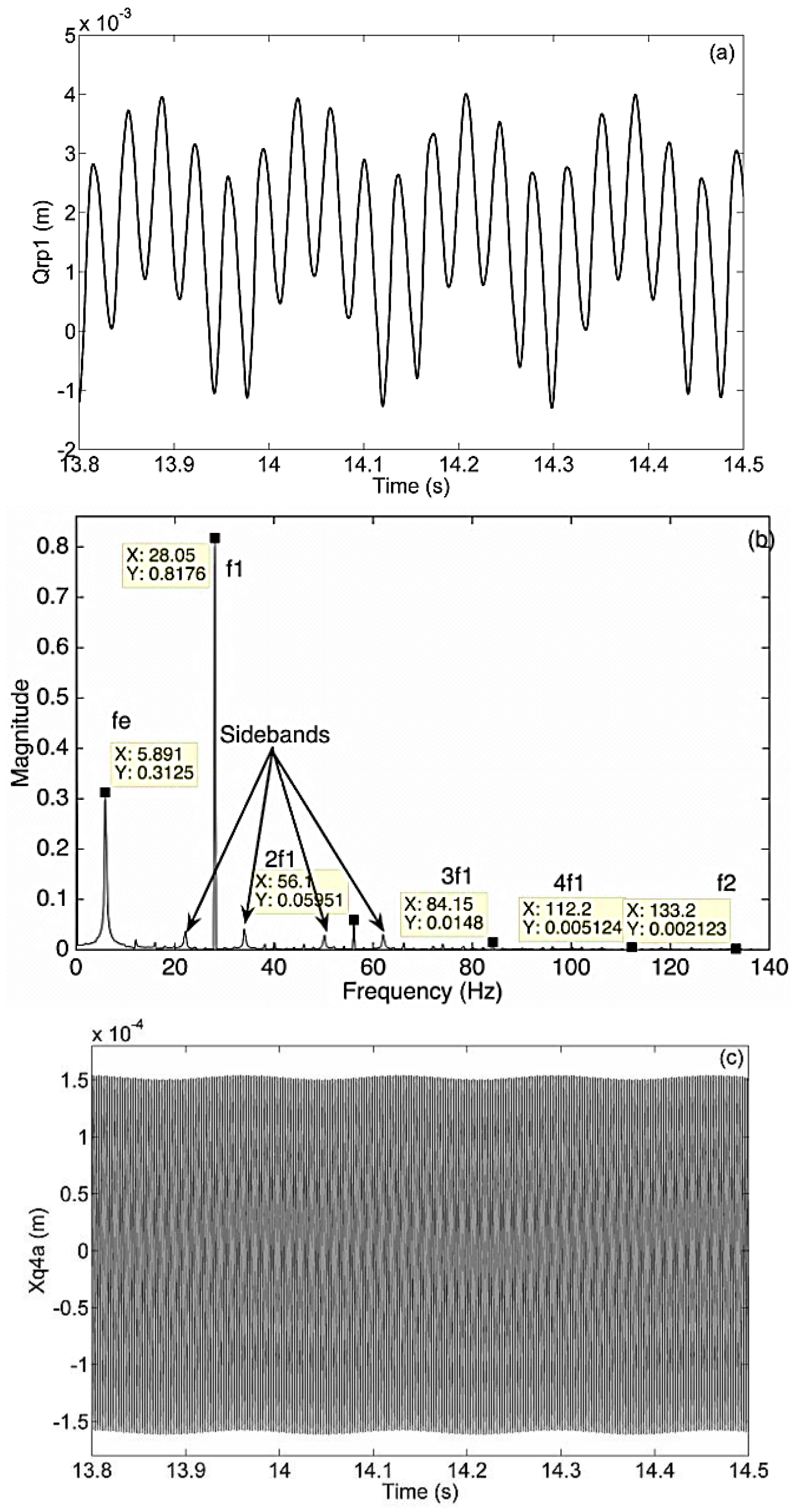
When both the internal and external excitation fluctuations are taken into account, the total excitation is a combination of loads expressed by Equations (21) and (23). To study the effect of the wind fluctuation, the mean-to-fluctuating external force ratio is used. In this secton, is 5. Figure 7 shows the dynamic responses of and . As both the external excitation fluctuation (with the mean-to-fluctuating external force ratio of 5) and the internal excitation are considered, the dynamic responses with the external excitation frequency and the meshing frequencies are expected to be observed.
It can be seen from Figure 7b that both the meshing frequencies and the external excitation frequency exist. The magnitude of the external frequency component is smaller than the meshing frequency at its own gear stage . The magnitudes of its harmonics and are much smaller than . This indicates that the meshing frequency of the planetary gear stage contributes the most on . Figure 7c,d present the axial displacement of the bearing at the high-speed parallel gear stage . The frequency peak occurs at and its magnitude is much larger than and . The effect of is too small and can be ignored. This shows that contributes the most at the high-speed parallel gear stage. In short, the gear meshes at all three gear stages are relatively stable when the external fluctuation is small. However, the harmonics and their sidebands exist on the dynamic responses of the gears. When with the external fluctuations, the sidebands appeared in the FFT spectrum can be used to estimate the gear and bearing damage conditions.
5.4. Fluctuating External Excitation with The mean-to-Fluctuating External Force Ratio of 2
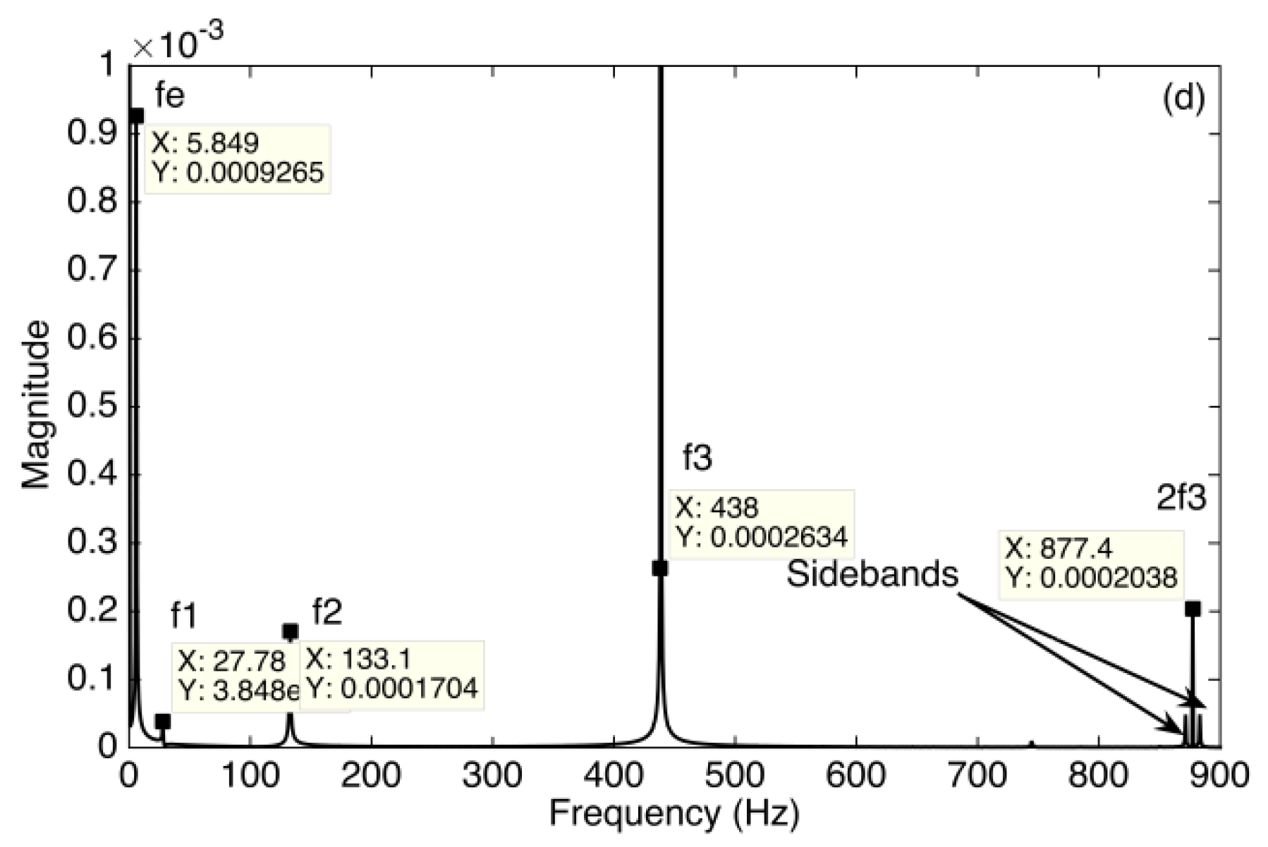
Similar to the previous section, the increased external excitation fluctuation (with the mean-to-fluctuating external force ratio of 2) and the internal excitation are considered in this section. Figure 8 presents the dynamic responses of and . As both the external excitation fluctuation and the internal excitation are considered, the external excitation frequency and the gear meshing frequencies are expected to be observed.
.
As shown in Figure 8a,b, the dynamic response of starts to have more fluctuations. The magnitude of the external frequency is still smaller than the meshing frequency at its own gear stage , but contributes more compared with that in Figure 7b. The harmonics and and their sidebands are observed. The magnitude of is much smaller than , which means that it provides much less effects on . Figure 8c,d present the zoomed image of the axial displacement of the bearing at the high-speed parallel gear stage . The frequency peak occurs at and its magnitude is much larger than , and . This shows that contributes the most at the high-speed parallel gear stage. Its harmonics 2 and sidebands are also observed. Compared with Figure 7 for when the mean-to-fluctuating force ratio is 5, the external excitation has larger influence on both the gears and bearings, which simulates the condition for a sudden change of external excitation on turbines.
6. Conclusions
The present work developed a 4-DOF dynamic model of a wind turbine gearbox, which takes into account both the low-frequency external excitation and the high-frequency internal excitation. This model includes the key factors such as the time-varying mesh stiffness, bearing stiffness, damping and gear backlash. Three excitation conditions on the wind turbine gearbox were studied: the external excitation only condition, the internal and constant external excitation condition; and the internal and fluctuating external excitation condition. The dynamic response of the gears and bearings of wind turbine gearboxes have been investigated with the help of time history and FFT spectrum.
In the study of the dynamic responses of the wind turbine gearbox components, when considering the external excitation only and disallowing gears to rotate, such a condition is similar to that when the wind turbine is parked. The results showed that the magnitude of the relative displacements of gear meshes is much larger than the elastic displacement of gearbox bearings. This explains why the fretting corrosion, as one of the wind turbine gearbox failure modes, occurs in gears along the line of action when the wind turbine is parked. When both the internal and external excitations were considered, it was observed that the gear meshes at all gear stages are relatively stable. When the external excitation fluctuation is small, the stability of gears is not affected. However, the dynamic responses of gears were observed to have more fluctuation. When the external excitation fluctuation is increased, the responses of gears and bearings were observed to have both the harmonics and sidebands in their FFT spectrums, which suggest that the external excitation fluctuation has large influence on wind turbine gearbox components, especially when a sudden change of external excitation is added. As a result, the dynamic responses of wind turbine gearbox components can be affected and may lead to gear wear and bearing failures.
Author Contributions
Mingming Zhao developed the mathematical model and performed the simulation. Both authors wrote and edited the manuscript.
Conflicts of Interest
The authors declare no conflict of interest.
References
- Ragheb, A.; Ragheb, M. Wind turbine gearbox technologies. In Proceedings of the 1st International Nuclear & Renewable Energy Conference (INREC), Amman, Jordan, 21–24 March 2010; pp. 1–8.
- American Gear Manufacturer Association. Standard for Design and Specification of Gearboxes for Wind Turbines; American Gear Manufacturer Association: Alexandria, VA, USA, 2004. [Google Scholar]
- Peeters, J.; Vandepitte, D.; Sas, P. Flexible multibody model of a three-stage planetary gearbox in a wind turbine. In Proceedings of the ISMA Conference, Leuven, Belgium, 20–22 September 2004; pp. 3923–3941.
- Peeters, J.; Vandepitte, D.; Sas, P. Structural analysis of a wind turbine and its drive train using the flexible multibody simulation technique. In Proceedings of the ISMA Conference, Leuven, Belgium, 18–20 September 2006; pp. 3665–3679.
- Helsen, J.; Vandepitte, D.; Desmet, W.; Peeters, J.; Goris, S.; Vanhollebeke, F.; Marrant, B.; Meeusen, W. From torsional towards flexible 6 DOF models for dynamic analysis of wind turbine gearboxes. In Proceedings of the European Wind Energy Conference and Exhibition (EWEC), Marseille, France, 16–19 March 2009.
- Peeters, J.L.; Vandepitte, D.; Sas, P. Analysis of internal drive train dynamics in a wind turbine. Wind Energy 2006, 9, 141–161. [Google Scholar] [CrossRef]
- Feng, Z.; Zuo, M.J. Fault diagnosis of planetary gearboxes via torsional vibration signal analysis. Mech. Syst. Signal Process. 2013, 36, 401–421. [Google Scholar] [CrossRef]
- Abboudi, K.; Walha, L.; Driss, Y.; Maatar, M.; Fakhfakh, T.; Haddar, M. Dynamic behavior of a two-stage gear train used in a fixed-speed wind turbine. Mech. Mach. Theory 2011, 46, 1888–1900. [Google Scholar] [CrossRef]
- Dong, W.; Xing, Y.; Moan, T.; Gao, Z. Time domain-based gear contact fatigue analysis of a wind turbine drivetrain under dynamic conditions. Int. J. Fatigue 2013, 48, 133–146. [Google Scholar] [CrossRef]
- Xing, Y.; Moan, T. Multi-body modelling and analysis of a planet carrier in a wind turbine gearbox. Wind Energy 2013, 16, 1067–1089. [Google Scholar] [CrossRef]
- Oyague, F. Gearbox Modeling and Load Simulation of a Baseline 750-kW Wind Turbine Using State-of-the-Art Simulation Codes; National Renewable Energy Laboratory (NREL): Golden, CO, USA, 2009. [Google Scholar]
- Oyague, F. Gearbox Reliability Collaborative (GRC) Description and Loading; National Renewable Energy Laboratory (NREL): Golden, CO, USA, 2011. [Google Scholar]
- Zhu, C.; Chen, S.; Liu, S.; Huang, H.; Li, G.; Ma, F. Dynamic analysis of the drive train of a wind turbine based upon the measured load spectrum. J. Mech. Sci. Technol. 2014, 28, 2033–2040. [Google Scholar] [CrossRef]
- Whittle, M.; Trevelyan, J.; Shin, W.; Tavner, P. Improving wind turbine drivetrain bearing reliability through pre-misalignment. Wind Energy 2014, 17, 1217–1230. [Google Scholar] [CrossRef] [Green Version]
- Zhang, Z.; Al-Zaidi, N.; Halse, C.; Crowther, A. The effect of transient loading on the stresses of wind turbine drivetrain components. In Proceedings of the European Wind Energy Conference and Exhibition (EWEC), Marseille, France, 16–19 March 2009.
- Zhao, M.; Ji, J.C. Nonlinear torsional vibrations of a wind turbine gearbox. Appl. Math. Model. 2015, 39, 4928–4950. [Google Scholar] [CrossRef]
- Özgüven, H.N.; Houser, D. Dynamic analysis of high speed gears by using loaded static transmission error. J. Sound Vib. 1988, 125, 71–83. [Google Scholar] [CrossRef]
- Kahraman, A.; Singh, R. Interations between time-varying mesh stiffness and clearance non-linearities in a geared system. J. Sound Vib. 1991, 146, 135–156. [Google Scholar] [CrossRef]
- Kahraman, A. Effect of axial vibrations on the dynamics of a helical gear pair. J. Vib. Acoust. 1993, 115, 33–39. [Google Scholar] [CrossRef]
- Kahraman, A. Dynamic analysis of a multi-mesh helical gear train. J. Mech. Design 1994, 116, 706–712. [Google Scholar] [CrossRef]
- Spitas, C.; Spitas, V. Calculation of overloads induced by indexing errors in spur gearboxes using multi-degree-of-freedom dynamical simulation. IMECE J. Multi-Body Dyn. 2006, 220, 273–282. [Google Scholar] [CrossRef]
- Spitas, C.; Spitas, V. Direct analytical solution of a modified form of the meshing equations in two dimensions for non-conjugate gear contact. Appl. Math. Model. 2008, 32, 2162–2171. [Google Scholar] [CrossRef]
- Spitas, C.; Spitas, V. Fast unconditionally stable 2-D analysis of non-conjugate gear contacts using an explicit formulation of the meshing equations. Mech. Mach. Theory 2011, 46, 869–879. [Google Scholar] [CrossRef]
- Spitas, C.; Spitas, V.; Amani, A. Multi-parametric investigation of interference in non-standard spur gear teeth. Mech. Mach. Theory 2015, 88, 105–124. [Google Scholar] [CrossRef]
- Spitas, C.; Spitas, V.; Amani, A.; Rajabalinejad, M. Parametric investigation of the combined effect of whole depth and cutter tip radius on the bending strength of 20° involute gear teeth. Acta Mech. 2014, 225, 361–371. [Google Scholar] [CrossRef]
- Holm-Jorgensen, K. Nonlinear multibody dynamics of wind turbines. Ph.D. Thesis, Aalborg University, Aalborg, Denmark, 2009. [Google Scholar]
- Todorov, M.; Vukov, G. Parametric torsional vibrations of a drive train in horizontal axis wind turbine. In Proceedings of the 1ère Conférence Franco-Syrienne sur les Energies Renouvelables, Damas, Syrie, 24–28 October 2010; pp. 1–17.
- Helsen, J.; Vanhollebeke, F.; de coninck, F.; Vandepitte, D.; Desmet, W. Insights in wind turbine drive train dynamics gathered by validating advanced models on a newly developed 13.2 MW dynamically controlled test-rig. Mechatronics 2011, 21, 737–752. [Google Scholar] [CrossRef]
- Amabili, M.; Rivola, A. Dynamic analysis of spur gear pairs steady-state response and stability of the SDOF model with time-varying meshing damping. Mech. Syst. Signal Process. 1997, 11, 375–390. [Google Scholar] [CrossRef]
- Masters, G.M. Renewable and Efficient Electric Power Systems; John Wiley & Sons: Hoboken, NJ, USA, 2005. [Google Scholar]
- Sun, T.; Hu, H.Y. Nonlinear dynamics of a planetary gear system with multiple clearances. Mech. Mach. Theory 2003, 38, 1371–1390. [Google Scholar] [CrossRef]
- Parker, R.G.; Lin, J. Mesh phasing relationships in planetary and epicyclic gears. J. Mech. Design 2004, 126, 365–370. [Google Scholar] [CrossRef]
- Norton, R.L. Machine Design: An Integrated Approach; Pearson Prentice Hall: Upper Saddle River, NJ, USA, 2006; Volume 3. [Google Scholar]
- ISO. In Calculation of Load Capacity of Spur and Helical Gears–Part 1: Basic Principles, Introduction and General Influence Factors; International Organization for Standardization: Geneva, Switzerland, 1996.
- Chang, C.J. Spur Gear Modeling. 2006. Available online: http://coewww.rutgers.edu/classes/mae/mae488/hw/lectures/gear/gear.htm (accessed on 16 September 2012).
- Sheng, S.; McDade, M.; Errichello, R. Wind turbine gearbox failure modes. In Proceedings of the International Joint Tribology Conference, Los Angeles, CA, USA, 24–26 October 2011.
Figure 1.
Sketch of the proposed wind turbine gearbox.

Figure 2.
Gear pairs in the planetary gear stage.

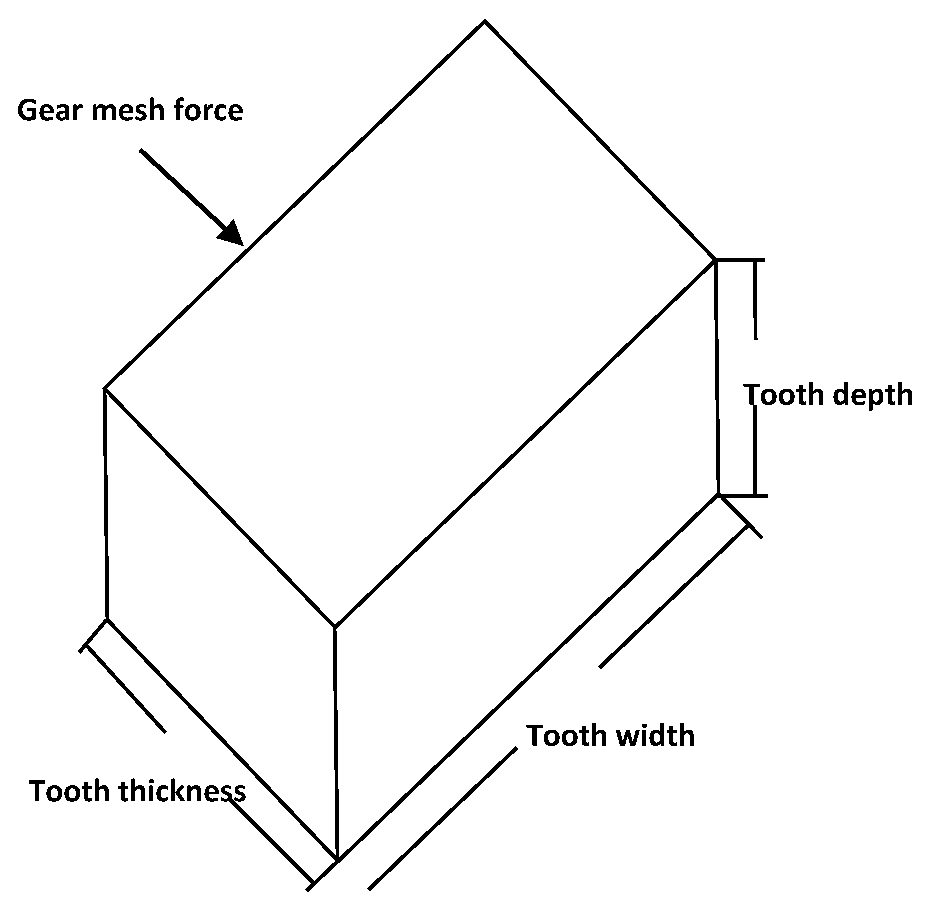
Figure 3.
Simplified model of a gear tooth.

Figure 4.
Nomenclature of a gear teeth [35].
Figure 4.
Nomenclature of a gear teeth [35].

Figure 5.
Time histories and frequency spectrums of vibrational responses caused by the external excitations only (a) Time history of ; (b) FFT spectrum of ; (c) Time history of ; (d) FFT spectrum of .
Figure 5.
Time histories and frequency spectrums of vibrational responses caused by the external excitations only (a) Time history of ; (b) FFT spectrum of ; (c) Time history of ; (d) FFT spectrum of .

Figure 6.
Time histories and frequency spectra of the vibrational responses caused by both the internal and constant external excitations (a) Time history of ; (b) FFT spectrum of ; (c) Time history of ; (d) FFT spectrum of .
Figure 6.
Time histories and frequency spectra of the vibrational responses caused by both the internal and constant external excitations (a) Time history of ; (b) FFT spectrum of ; (c) Time history of ; (d) FFT spectrum of .

Figure 7.
Time histories and frequency spectra of the vibrational responses caused by both the internal and external excitations with the mean-to-fluctuating external force ratio of 5 (a) Time history of ; (b) FFT spectrum of ; (c) Time history of ; (d) FFT spectrum of .
Figure 7.
Time histories and frequency spectra of the vibrational responses caused by both the internal and external excitations with the mean-to-fluctuating external force ratio of 5 (a) Time history of ; (b) FFT spectrum of ; (c) Time history of ; (d) FFT spectrum of .

Figure 8.
Time histories and frequency spectra of the vibrational responses caused by both the internal and external excitations with the mean-to-fluctuating external force ratio of 2 (a) Time history of ; (b) FFT spectrum of ; (c) Time history of ; (d) zoomed FFT spectrum of .
Figure 8.
Time histories and frequency spectra of the vibrational responses caused by both the internal and external excitations with the mean-to-fluctuating external force ratio of 2 (a) Time history of ; (b) FFT spectrum of ; (c) Time history of ; (d) zoomed FFT spectrum of .


Table 1.
AGMA full-depth gear tooth specifications [33].
| Parameters | Coarse Pitch () |
|---|---|
| Pressure angle | 20 |
| Addendum | |
| Dedendum | |
| Whole depth |
| Gears | Teeth | Module | ||||||
|---|---|---|---|---|---|---|---|---|
| Ring | 99 | 10 | 2.540 | 0.0100 | 0.0125 | 0.0225 | 0.0089 | 7.5 L |
| Planet | 39 | 10 | 2.540 | 0.0100 | 0.0125 | 0.0225 | 0.0187 | 7.5 L |
| Sun | 21 | 10 | 2.540 | 0.0100 | 0.0125 | 0.0225 | 0.0172 | 7.5 L |
| 82 | 8 | 3.175 | 0.0080 | 0.0100 | 0.0180 | 0.0149 | 14 R | |
| 23 | 8 | 3.175 | 0.0080 | 0.0100 | 0.0180 | 0.0137 | 14 L | |
| 76 | 5.5 | 4.618 | 0.0055 | 0.0069 | 0.0124 | 0.0103 | 14 L | |
| 23 | 5.5 | 4.618 | 0.0055 | 0.0069 | 0.0124 | 0.0103 | 14 R |
| Carrier | Sun | Planet | |||||
|---|---|---|---|---|---|---|---|
| () | 2 × | 2 × | |||||
| () | 3.2 × | 2 × | 3.2 × | 2.9 × | 2.9 × | 2.9 × | 2.9 |
| () | 3.2 × | 2 × | 3.2 × | 2.9 × | 2.9 × | 2.9 | 2.9 |
© 2016 by the authors; licensee MDPI, Basel, Switzerland. This article is an open access article distributed under the terms and conditions of the Creative Commons by Attribution (CC-BY) license (http://creativecommons.org/licenses/by/4.0/).
Share and Cite
MDPI and ACS Style
Zhao, M.; Ji, J. Dynamic Analysis of Wind Turbine Gearbox Components. Energies 2016, 9, 110. https://doi.org/10.3390/en9020110
AMA Style
Zhao M, Ji J. Dynamic Analysis of Wind Turbine Gearbox Components. Energies. 2016; 9(2):110. https://doi.org/10.3390/en9020110
Chicago/Turabian StyleZhao, Mingming, and Jinchen Ji. 2016. "Dynamic Analysis of Wind Turbine Gearbox Components" Energies 9, no. 2: 110. https://doi.org/10.3390/en9020110
Note that from the first issue of 2016, this journal uses article numbers instead of page numbers. See further details here.